EP2238021B1 - Systeme d'assemblage pour assembler deux elements de renforcement presentant differents profils de section transversale pour aeronef ou vaisseau spatial, et element monocoque - Google Patents
Systeme d'assemblage pour assembler deux elements de renforcement presentant differents profils de section transversale pour aeronef ou vaisseau spatial, et element monocoque Download PDFInfo
- Publication number
- EP2238021B1 EP2238021B1 EP08871637A EP08871637A EP2238021B1 EP 2238021 B1 EP2238021 B1 EP 2238021B1 EP 08871637 A EP08871637 A EP 08871637A EP 08871637 A EP08871637 A EP 08871637A EP 2238021 B1 EP2238021 B1 EP 2238021B1
- Authority
- EP
- European Patent Office
- Prior art keywords
- elements
- comb
- reinforcing
- foot
- portion connecting
- Prior art date
- Legal status (The legal status is an assumption and is not a legal conclusion. Google has not performed a legal analysis and makes no representation as to the accuracy of the status listed.)
- Not-in-force
Links
- 230000003014 reinforcing effect Effects 0.000 claims abstract description 31
- 230000008878 coupling Effects 0.000 claims description 39
- 238000010168 coupling process Methods 0.000 claims description 39
- 238000005859 coupling reaction Methods 0.000 claims description 39
- 239000002131 composite material Substances 0.000 claims description 8
- 239000002184 metal Substances 0.000 claims description 5
- 239000000835 fiber Substances 0.000 description 8
- 238000013461 design Methods 0.000 description 5
- 238000007689 inspection Methods 0.000 description 5
- 230000005540 biological transmission Effects 0.000 description 4
- 238000000034 method Methods 0.000 description 4
- 238000010276 construction Methods 0.000 description 3
- 238000004519 manufacturing process Methods 0.000 description 3
- 238000012423 maintenance Methods 0.000 description 2
- 239000000463 material Substances 0.000 description 2
- 229920000049 Carbon (fiber) Polymers 0.000 description 1
- 238000013459 approach Methods 0.000 description 1
- 230000015572 biosynthetic process Effects 0.000 description 1
- 239000007767 bonding agent Substances 0.000 description 1
- 230000009172 bursting Effects 0.000 description 1
- 239000004917 carbon fiber Substances 0.000 description 1
- 238000005336 cracking Methods 0.000 description 1
- 230000001419 dependent effect Effects 0.000 description 1
- 239000003822 epoxy resin Substances 0.000 description 1
- 238000001802 infusion Methods 0.000 description 1
- 239000011159 matrix material Substances 0.000 description 1
- 239000007769 metal material Substances 0.000 description 1
- VNWKTOKETHGBQD-UHFFFAOYSA-N methane Chemical compound C VNWKTOKETHGBQD-UHFFFAOYSA-N 0.000 description 1
- 239000004033 plastic Substances 0.000 description 1
- 229920000647 polyepoxide Polymers 0.000 description 1
- 230000003068 static effect Effects 0.000 description 1
Images


Classifications
-
- B—PERFORMING OPERATIONS; TRANSPORTING
- B64—AIRCRAFT; AVIATION; COSMONAUTICS
- B64C—AEROPLANES; HELICOPTERS
- B64C1/00—Fuselages; Constructional features common to fuselages, wings, stabilising surfaces or the like
- B64C1/06—Frames; Stringers; Longerons ; Fuselage sections
- B64C1/064—Stringers; Longerons
-
- B—PERFORMING OPERATIONS; TRANSPORTING
- B64—AIRCRAFT; AVIATION; COSMONAUTICS
- B64C—AEROPLANES; HELICOPTERS
- B64C1/00—Fuselages; Constructional features common to fuselages, wings, stabilising surfaces or the like
- B64C2001/0054—Fuselage structures substantially made from particular materials
- B64C2001/0072—Fuselage structures substantially made from particular materials from composite materials
-
- Y—GENERAL TAGGING OF NEW TECHNOLOGICAL DEVELOPMENTS; GENERAL TAGGING OF CROSS-SECTIONAL TECHNOLOGIES SPANNING OVER SEVERAL SECTIONS OF THE IPC; TECHNICAL SUBJECTS COVERED BY FORMER USPC CROSS-REFERENCE ART COLLECTIONS [XRACs] AND DIGESTS
- Y02—TECHNOLOGIES OR APPLICATIONS FOR MITIGATION OR ADAPTATION AGAINST CLIMATE CHANGE
- Y02T—CLIMATE CHANGE MITIGATION TECHNOLOGIES RELATED TO TRANSPORTATION
- Y02T50/00—Aeronautics or air transport
- Y02T50/40—Weight reduction
-
- Y—GENERAL TAGGING OF NEW TECHNOLOGICAL DEVELOPMENTS; GENERAL TAGGING OF CROSS-SECTIONAL TECHNOLOGIES SPANNING OVER SEVERAL SECTIONS OF THE IPC; TECHNICAL SUBJECTS COVERED BY FORMER USPC CROSS-REFERENCE ART COLLECTIONS [XRACs] AND DIGESTS
- Y10—TECHNICAL SUBJECTS COVERED BY FORMER USPC
- Y10T—TECHNICAL SUBJECTS COVERED BY FORMER US CLASSIFICATION
- Y10T403/00—Joints and connections
- Y10T403/70—Interfitted members
Definitions
- the present invention relates to a connection arrangement for connecting two stiffening elements of different cross-sectional profile for an aircraft or spacecraft, and a shell component.
- CFRP carbon fiber plastic
- CFRP stringers In order to withstand the high loads in the aircraft or spacecraft sector with the least possible additional weight.
- T and Omega stringers two types of stringers are distinguished: T and Omega stringers.
- T-stringers have a narrow head portion and a wide foot portion. At the foot portion they are connected to the skin shell and have the advantage of easy manufacturability.
- Omega stringer have approximately a hat profile, the ends of which are connected as a foot section to the skin shell.
- fiber composite components are widely used in aircraft construction. They are for example by Vakuuminfusionsclar for introducing a matrix, such as an epoxy resin, in semi-finished fiber products and subsequent curing produced. Infusion methods may be cost effective over other known methods of making fiber composite components, such as the prepreg method, because this allows for the use of less expensive semi-finished fiber products.
- the object of the present invention is to provide a connection arrangement for stiffening elements in order to remedy or substantially reduce the abovementioned disadvantages.
- connection arrangement having the features of patent claim 1 and a shell component having the features of patent claim 10.
- connection arrangement for connecting two stiffening elements of an aircraft or spacecraft.
- the stiffening elements have different cross-sectional profiles, each with at least one foot section and at least one comb section.
- the connection arrangement comprises at least one foot portion connecting element, which on one side to the geometric shape of the foot portion of the first stiffening element and on the opposite side to the geometric shape of the foot portion the second stiffening element customizable and is permanently connected to these.
- the connection arrangement has at least one comb portion connecting element which is adaptable on one side to the geometric shape of the comb portion of the first stiffening element and on the opposite side to the geometric shape of the comb portion of the second stiffening element and fixedly connected thereto.
- a shell component of an aircraft or spacecraft has at least two stiffening elements of different cross-sectional profile. These stiffening elements are connected in their longitudinal direction by means of a connection arrangement described above.
- a basic idea of the invention is to provide a connection arrangement with a predominantlyabites- and a comb portion connecting element, which are adapted to the different geometric shapes of the connecting stiffening elements.
- the present invention over the approaches mentioned above, inter alia, has the advantage that it is possible in one embodiment to couple stiffening elements with different cross-sectional profile even when offset the same without additional shims, in another embodiment, the possibility exists, stiffening elements with different Cross-sectional profile on a shell component as well as at a junction of shell elements of a shell component to couple with the same connection arrangement and thereby have a minimal parts cost.
- a foot section connecting element and a comb section connecting element on both sides of the comb portions of the stiffening elements to be connected to the corresponding foot portions and comb portions are connectable.
- This connection can be made by riveting, for example.
- the foot section connecting elements are formed in one embodiment as L-profiles, but may also be, for example, flat material. By a construction independent of the comb section fasteners, individual adjustments are easily made.
- the comb-section connecting elements are provided on both sides of the comb portions of the stiffening elements to be joined in a preferred embodiment in mirror-image formation.
- laterally offset stiffening elements of the offset can be compensated by different height arrangements of the same comb-section connecting elements without shims or shims.
- the foot section connecting elements can be cut to length, for example, for both sides of the connection assembly from the same profile bar, with no mirror image execution are necessary.
- the comb portion connecting element has a coupling surface for connection to the first stiffening element and a coupling profile surface for connection to the second stiffening element, wherein the coupling surface and the coupling profile surface are connected to longitudinal connection edges via a connecting web.
- the comb-section connecting element can be designed, for example, in metal design as a cost-effective stamped and bent part in a single operation. But also a version as a composite part in CFK or the like is possible.
- With a curved comb portion connecting member it is possible to easily control the different profiles of the reinforcing members in the longitudinal direction thereof, which is maintenance and inspection work In terms of control on cracking considerably simplified, since no disassembly of components but only one inspection is required.
- the foot section connecting element is preferably designed as an L-profile and can thus be cut particularly cost-effectively as a rod product.
- Other profile shapes are of course conceivable.
- the foot section connecting elements can be cut to length, for example, for both sides of the connection assembly from the same profile bar, with no mirror image execution are necessary.
- the stiffening elements may be formed, for example, as a T-stringer and omega stringer.
- the comb portion connecting element is integrally formed together with a foot portion connecting element.
- the foot portion connecting element may be integrally formed as a foot coupling surface with the coupling profile surface and / or with the coupling surface of the comb portion connecting element. This is particularly advantageous in the longitudinal direction in its central axis aligned stiffening elements of advantage, since the number of parts is further reduced. But laterally staggered stiffening elements are coupled so can be used for tolerance compensation shims.
- At least one leg section of the stiffening elements is widened at the connection point of the stiffening elements.
- a larger bearing surface for the foot section connecting elements for an advantageously large force transmission and rigidity increase is created.
- stiffening elements of different profile cross-sections are laterally offset at their junctions by means of the alternative connection arrangement described above or connected to additional shims for tolerance compensation by means of a described connection arrangement.
- the foot portion connecting elements whether they are formed separately from or integral with the comb portion connecting elements, for example, as sinekoppelanni, firmly connected to the crossbar, which significantly increases the rigidity and power transmission capability of the joint.
- the independent design of the components of the connecting arrangement saves shims in a staggered arrangement of the stiffening elements, and on the other hand, in the integral construction, that is to say that the foot section connecting elements are formed integrally with the comb-section connecting elements, components are saved, but production times at each Version reduced. Due to the open design in the form of, for example stamped parts and recesses stiffening elements, the inspectability is not only guaranteed by this open design, but also simplified and shortened.
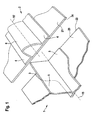
- Fig. 1 shows a schematic representation of two stiffening elements 1, 2 different profile cross section with central axes 15, 15 ', which extend in their longitudinal directions.
- the stiffening elements 1, 2 are here applied to shell elements 20, 21, for example a shell component, to the stiffening thereof.
- the shell elements 20, 21 are, for example, skin shells for an aircraft and are made of a fiber composite material, but also a metallic material is possible.
- the two stiffening elements 1, 2 are arranged here at the edge of a connection point of the shell elements 20, 21.
- the shell elements 20, 21 have at this connection point transverse edge edges 23, 24, against which they abut each other in a connection. This connection will be explained below.
- the first stiffening element 1 is here designed as a T-stringer with a foot section 3 and a comb section 5.
- the second stiffening element 2 has a hollow profile cross-section with a comb portion 6 and foot portion 4 and is referred to in this embodiment as an omega stringer.
- the Fig. 1 shows the stiffening elements 1, 2 at the edge of the shell elements 20, 21.
- the two stiffening elements 1, 2 different profile cross section together on a shell member or a shell member 20, 21 are arranged somewhere on the surface and to connect with each other ,
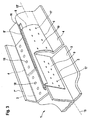
- a comb portion connecting element 8 which in Fig. 2 is shown as an embodiment of a connection arrangement according to the invention.
- the Fig. 2 will be together with Fig. 3 explains which a schematic perspective view of a first embodiment of a connection arrangement according to the invention with the comb portion connecting element 8 after Fig. 2 for the stiffening elements 1, 2 according to Fig. 1 shows.
- the comb portion connecting element 8 has a flat coupling surface 9, which corresponds to the comb portion 5 of the first stiffening element 1, the T-stringer.
- a connecting web 13 is formed, which extends over the entire L Lucassinformationsrad 11, further extends beyond its longitudinal direction and is connected to a longitudinal connection edge 12 of a coupling profile surface 10.
- the coupling profile surface 10 corresponds in shape to the outer surface of the second stiffening element 2, the omega stringer.
- the connecting web 13 is bent in this example in each case at the longitudinal edges 11 and 12 by a predetermined amount and a certain radius that a certain rigidity of the comb portion connecting element 8 is achieved.
- the comb portion connecting element 8 may be made of metal and / or fiber composite material. For example, it is made of metal as a stamped and bent part easily executable.
- the two stiffening elements 1, 2 are applied to a shell element, not shown here, or at their edges, as in FIG Fig. 1 is shown.
- the central axes 15, 15 'of the stiffening elements 1, 2 are aligned in a line and aligned with each other.
- the comb-section connecting element 8 is fixedly attached here with the flat coupling surface 9 on the comb portion 5 of the T-stringer 1, for example by means of rivets as a comb attachment 17.
- the coupling profile surface 10 of the comb-section connecting element 8 is mounted in the same manner on the comb portion 6 of the omega-stringer 2.
- foot section connecting elements 7, 7 ' are provided, of which only one is shown here. It is formed in this example as L-profile and, like the comb portion connecting element 8, 8 'made of metal and / or fiber composite material. As a profile it is advantageous simply cut to length as a rod material. On its underside, it rests on the foot sections 3, 4 of the stiffening elements 1, 2 to be joined, and is firmly connected to these, for example by means of rivets, in foot fasteners 18. In order to obtain a large force transmission surface, the foot portion 3 of the T-stringer 1 is widened in this example and adapted to the foot portion of the omega-stringer 2. However, the widening at this connection point can be adjusted correspondingly in accordance with the execution beforehand.
- Fig. 3 the stiffening elements 1, 2 are aligned with aligned central axes 15, 15 '.
- Fig. 4 provides a view of the Fig. 3 in the direction of the central axes 15, 15 '.
- Fig. 4 is that too in Fig. 3 not shown second foot section connecting element 7 shown.
- This arrangement is symmetrical to the plane in which the aligned central axis 15, 15 'extend. It is also conceivable that in each case only one of them (for example 7 and 8 ') or in another combination can be used instead of the respective double connecting elements 7, 7' and 8, 8 '.
- the Fig. 5 in a view shown in the longitudinal direction of the central axis 15, 15 'of the Fig. 3 compared to Fig. 4 shows this offset with the first embodiment of the comb portion connecting element 8, 8 'of the connection arrangement according to the invention advantageously without intermediate layers, which are also referred to as shims, in a certain tolerance range thereby be compensated by the two comb section connecting elements 8, 8' on
- the sloping outer surface of the Omega Stringer 2 can be moved either upwards or downwards depending on the offset direction.
- a shimtransport coupling between the comb sections 5 and 6 is guaranteed.
- FIG. 6 Another embodiment of the comb portion connecting element 8 of the connection arrangement according to the invention is in Fig. 6 shown in connection with Fig. 7 is explained.
- Fig. 7 is a schematic perspective view of a second embodiment of the connection arrangement according to the invention with the comb portion connecting element 8 after Fig. 6 for the stiffening elements Fig. 1 ,
- the foot portion connecting member 7 in the form of a foot coupling surface 14 with the comb portion connecting member 8 is integrally formed.
- the foot coupling surface 14 is attached to a longitudinal edge of the coupling profile surface 10, which lies opposite the longitudinal connection edge 12.
- the remaining comb portion connecting element 8 is like that of the first embodiment according to Fig. 2 built up.
- Thenackoppel structures 14 may of course be configured as L-profile or the like.
- Fig. 7 is similar to that Fig. 3 built and already described there.
- the difference to Fig. 3 is that the comb portion connecting elements 8, 8 'integral with the foot portion connecting elements 7, 7', here as documentkoppel lake 14, 14 'are executed.
- the integral comb portion connecting element 8, 8 ' has the advantage of a small number of parts compared to the first embodiment.
- shims are to be used here as intermediate layers for compensation.
- FIG. 9 shows a third embodiment of the connection arrangement according to the invention with the comb portion connecting elements 8, 8 'of the embodiment according to Fig. 8 in an extension of the coupling surfaces 9 to 9 'and thus with molded foot coupling surfaces 14, 14' at a junction of the shell elements 20, 21 to Fig. 1 ,
- the foot section connecting elements 7, 7 ' are provided for connecting the foot sections 3 and 4, wherein the foot section connecting element 7 otherwise located in the foreground is not shown.
- This connection point of the shell elements 20, 21 has a transverse bursting tab 22, which will not be explained further.
- the stiffening elements 1, 2 from both sides and have between them a gap which is bridged by the extended coupling surfaces 9 '.
- the comb-section connecting elements 8, 8 ' are, as mentioned above, connected to the corresponding comb sections 5, 6 of the stiffening elements 1, 2.
- the foot coupling surfaces 14, 14 'and the foot section connecting elements 7, 7' are fixedly connected to the foot sections 3, 4 of the stiffening elements 1, 2 in foot fasteners 18 as indicated above.
- foot portion connecting elements 7, 7 'and the schizophreniakoppel vom 14, 14' with their sections which are located above the transverse butt strap 22, with this transverse butt strap 22 in cross joint fasteners 19, for example by riveting, also firmly connected, so a special to achieve high rigidity and strength of the connection arrangement.
- the coupling surface 9 of the comb-section connecting element 8, 8 ' may extend further behind the coupling profile surface 10. These too can continue to expand in front of the coupling surface 9, whereby a higher strength and rigidity can be achieved.
- the stiffening elements 1, 2 to be connected with the connection arrangement according to the invention can be arranged at any point on a shell element 20, 21, as well as at a connection point of the shell elements 20, 21 with or without cross-bracing flap 22.
- connection arrangement for connecting two stiffening elements 1, 2 of an aircraft or spacecraft
- the stiffening elements 1, 2 having different cross-sectional profiles, each with at least one foot section 3, 4 and at least one comb section 5, 6, is at least one foot section connecting element 7, 7 ', which on one side to the geometric shape of the foot portion 3 of the first stiffening element 1 and on the opposite side of the geometric shape of the foot portion 4 of the second reinforcing element 2 adaptable and connected to these in each case fixedly; and at least one comb portion connecting element 8, 8 ', which on one side to the geometric shape of the comb portion 5 of the first stiffening element 1 and on the opposite side to the geometric shape of the comb portion 6 of the second reinforcing element 2 adaptable and fixedly connected to these.
- a shell component with at least two stiffening elements 1, 2 different profile cross section has the connection arrangement.
Landscapes
- Engineering & Computer Science (AREA)
- Mechanical Engineering (AREA)
- Aviation & Aerospace Engineering (AREA)
- Connection Of Plates (AREA)
- Moulding By Coating Moulds (AREA)
- Bridges Or Land Bridges (AREA)
- Lining Or Joining Of Plastics Or The Like (AREA)
- Pressure Welding/Diffusion-Bonding (AREA)
- Standing Axle, Rod, Or Tube Structures Coupled By Welding, Adhesion, Or Deposition (AREA)
- Reinforcement Elements For Buildings (AREA)
- Body Structure For Vehicles (AREA)
Claims (17)
- Système d'assemblage permettant d'assembler deux éléments de renforcement (1, 2) d'un aéronef ou véhicule spatial, les éléments de renforcement (1 , 2) présentant différents profils de section avec à chaque fois au moins un segment de pied (3, 4) et au moins un segment de crête (5, 6), comprenant :- au moins un élément d'assemblage de segment de pied (7, 7'), qui peut être adapté et à chaque fois rigidement relié à la forme géométrique du segment de pied (3) du premier élément de renforcement (1) d'un côté et à la forme géométrique du segment de pied (4) du second élément de renforcement (2) du côté opposé ; et- au moins un élément d'assemblage de segment de crête (8, 8'), qui peut être adapté et à chaque fois rigidement relié à la forme géométrique du segment de crête (5) du premier élément de renforcement (1) d'un côté et à la forme géométrique du segment de crête (6) du second élément de renforcement (2) du côté opposé.
- Système d'assemblage selon la revendication 1, caractérisé en ce qu'un élément d'assemblage de segment de pied (7, 7') et un élément d'assemblage de segment de crête (8, 8') de part et d'autre des segments de crête (5, 6) des éléments de renforcement à assembler (1, 2) peuvent chacun être reliés aux segments de pied (3, 4) et aux segments de crête (5, b) correspondants.
- Système d'assemblage selon la revendication 1 ou 2, caractérisé en ce que l'élément d'assemblage de segment de crête (8, 8') présente une surface d'accouplement (9) permettant un assemblage avec le premier élément de renforcement (1) et une surface profilée d'accouplement (10) permettant un assemblage avec le second élément de renforcement (2), la surface d'accouplement (9) et la surface profilée d'accouplement (10) étant reliées à des bords de liaison longitudinaux (11, 12) par une nervure de liaison (13).
- Système d'assemblage selon au moins une des revendications précédentes, caractérisé en ce que l'élément d'assemblage de segment de pied (7, 7') présente un profilé.
- Système d'assemblage selon au moins une des revendications précédentes, caractérisé en ce que l'élément d'assemblage de segment de crête (8, 8') est adapté pour assembler un élément de renforcement (1) ayant la forme d'un raidisseur en T et un élément de renforcement (1) ayant la forme d'un raidisseur de profil oméga.
- Système d'assemblage selon au moins une des revendications précédentes, caractérisé en ce que l'élément d'assemblage de segment de pied (7, 7') et l'élément d'assemblage de segment de crête (8, 8') sont conçus à partir d'un matériau métallique et/ou d'un matériau composite.
- Système d'assemblage selon au moins une des revendications précédentes, caractérisé en ce que l'élément d'assemblage de segment de pied (7, 7') et l'élément d'assemblage de segment de crête (8, 8') sont conçus de manière à pouvoir être assemblés aux éléments de renforcement à assembler (1, 2) pour des assemblages rivés.
- Système d'assemblage selon au moins une des revendications précédentes, caractérisé en ce que l'élément d'assemblage de segment de crête (8, 8') est conçu d'un seul tenant avec l'élément d'assemblage de segment de pied (7, 7').
- Système d'assemblage selon la revendication 8, caractérisé en ce que l'élément d'assemblage de segment de pied (7, 7') est réalisé comme une surface d'accouplement de pied (14) solidaire de la surface profilée d'accouplement (10) et/ou de la surface d'accouplement (9) de l'élément d'assemblage de segment de crête (8, 8').
- Composant de coque d'un aéronef ou véhicule spatial, comprenant au moins deux éléments de renforcement (1, 2) de profils de section différents, les éléments de renforcement (1, 2) étant reliés dans leur sens longitudinal à l'aide d'un système d'assemblage selon au moins une des revendications précédentes, ou les éléments de renforcement (1, 2) étant reliés en décalage latéral dans leur sens longitudinal à l'aide d'un système d'assemblage selon au moins une des revendications 1 à 7, ou à l'aide d'un système d'assemblage selon au moins une des revendications 1 à 9 avec des cales supplémentaires assurant une compensation des tolérances.
- Composant de coque selon la revendication 10, caractérisé en ce que le composant de coque présente au moins deux éléments de coque assemblés (20, 21).
- Composant de coque selon la revendication 11, caractérisé en ce que les au moins deux éléments de coque assemblés (20, 21) sont reliés à une patte de raccord transversal (22).
- Composant de coque selon au moins une des revendications 10 à 12, caractérisé en ce que le premier élément de renforcement (1) est un raidisseur à profil en T et l'autre élément de renforcement (2) est un raidisseur de profil oméga.
- Composant de coque selon au moins une des revendications 10 à 13, caractérisé en ce qu'au moins un segment de pied (3, 4) des éléments de renforcement (1, 2) est élargi au point de jonction des éléments de renforcement (1, 2).
- Composant de coque selon la revendication 13 ou 14, caractérisé en ce que l'élément de renforcement (2) conçu sous forme de raidisseur de profil oméga présente sur sa face supérieure, au niveau du système d'assemblage, un évidement (16) s'étendant dans le sens longitudinal.
- Composant de coque selon au moins une des revendications 10 à 15, caractérisé en ce que les éléments d'assemblage de segment de crête (8, 8') sont conçus en symétrie.
- Composant de coque selon au moins une des revendications 12 à 16, caractérisé en ce que dans le cas d'éléments de renforcement (1, 2) de différentes sections de profil étant disposés de manière liée au niveau du point de jonction des éléments de coque à l'aide du système d'assemblage, les éléments d'assemblage de segment de pied (7, 7') et/ou les surfaces d'accouplement de pied (14) des éléments d'assemblage de segment de crête (8, 8') du système d'assemblage sont reliés à la patte de raccord transversal (22).
Applications Claiming Priority (3)
| Application Number | Priority Date | Filing Date | Title |
|---|---|---|---|
| US6301208P | 2008-01-30 | 2008-01-30 | |
| DE102008006834A DE102008006834A1 (de) | 2008-01-30 | 2008-01-30 | Verbindungsanordnung zum Verbinden zweier Versteifungselemente unterschiedlichen Querschnittprofils für ein Luft- oder Raumfahrzeug, und ein Schalenbauteil |
| PCT/EP2008/067214 WO2009095133A2 (fr) | 2008-01-30 | 2008-12-10 | Système d'assemblage pour assembler deux éléments de renforcement présentant différents profils de section transversale pour aéronef ou vaisseau spatial, et élément monocoque |
Publications (2)
| Publication Number | Publication Date |
|---|---|
| EP2238021A2 EP2238021A2 (fr) | 2010-10-13 |
| EP2238021B1 true EP2238021B1 (fr) | 2011-04-13 |
Family
ID=40913325
Family Applications (1)
| Application Number | Title | Priority Date | Filing Date |
|---|---|---|---|
| EP08871637A Not-in-force EP2238021B1 (fr) | 2008-01-30 | 2008-12-10 | Systeme d'assemblage pour assembler deux elements de renforcement presentant differents profils de section transversale pour aeronef ou vaisseau spatial, et element monocoque |
Country Status (10)
| Country | Link |
|---|---|
| US (1) | US8528865B2 (fr) |
| EP (1) | EP2238021B1 (fr) |
| JP (1) | JP2011510859A (fr) |
| CN (1) | CN101932506B (fr) |
| AT (1) | ATE505398T1 (fr) |
| BR (1) | BRPI0822041A2 (fr) |
| CA (1) | CA2712062A1 (fr) |
| DE (2) | DE102008006834A1 (fr) |
| RU (1) | RU2482017C2 (fr) |
| WO (1) | WO2009095133A2 (fr) |
Families Citing this family (12)
| Publication number | Priority date | Publication date | Assignee | Title |
|---|---|---|---|---|
| DE102008012252B4 (de) | 2008-03-03 | 2014-07-31 | Airbus Operations Gmbh | Verbund sowie Luft- oder Raumfahrzeug mit einem derartigen Verbund |
| ES2384250B1 (es) * | 2009-09-30 | 2013-05-16 | Airbus Operations, S.L. | Unión de elementos estructurales de aeronave. |
| DE102010042970A1 (de) * | 2010-05-12 | 2011-11-17 | Airbus Operations Gmbh | Strukturbauteil mit verbesserter Leitfähigkeit und mechanischer Festigkeit sowie Verfahren zu dessen Herstellung |
| ES2398985B1 (es) * | 2011-03-14 | 2014-02-14 | Airbus Operations S.L. | Dispositivos de transferencia de carga en la terminación de un larguerillo. |
| FR2984844B1 (fr) * | 2011-12-21 | 2014-02-28 | Airbus Operations Sas | Element de structure de fuselage d'aeronef anti deversement |
| FR2993856B1 (fr) * | 2012-07-30 | 2015-09-18 | Airbus Operations Sas | Element de structure de fuselage d'aeronef a section evolutive |
| FR3007735B1 (fr) * | 2013-06-28 | 2015-08-07 | Airbus Operations Sas | Liaison d'un element de fuselage d'aeronef et d'un cadre par une entretoise et une cale |
| US9656319B2 (en) * | 2013-11-13 | 2017-05-23 | The Boeing Company | Positioning system for electromagnetic riveting |
| EP2907743A1 (fr) * | 2014-02-13 | 2015-08-19 | Airbus Operations GmbH | Élément de renfort, procédé permettant de le coupler et élément de coque pour aéronef ou engin spatial |
| US9724848B2 (en) * | 2014-07-03 | 2017-08-08 | The Boeing Company | Collapsible, coiled mandrel |
| US11198497B2 (en) | 2019-06-19 | 2021-12-14 | The Boeing Company | Splice fittings that are affixed to stringers via web-installed fasteners |
| CN113290117B (zh) * | 2021-05-21 | 2022-09-09 | 青岛中天鹏锻压制造有限公司 | 一种轨道交通车辆牵引梁腹板塑性成形方法及其模具 |
Family Cites Families (28)
| Publication number | Priority date | Publication date | Assignee | Title |
|---|---|---|---|---|
| US1854330A (en) * | 1928-12-20 | 1932-04-19 | Nieuportastra Sa | Metallic construction of aircraft |
| US2383634A (en) * | 1943-02-20 | 1945-08-28 | Budd Edward G Mfg Co | Main frame structure for airfoils or the like |
| US2382358A (en) * | 1944-02-03 | 1945-08-14 | Budd Edward G Mfg Co | Stressed skin airfoil joint |
| US3004645A (en) * | 1959-08-27 | 1961-10-17 | Jr George E Moul | Aerodynamic surface attaching structure |
| US3827661A (en) * | 1972-07-26 | 1974-08-06 | Ryson Aviat Corp | Aircraft wing structure and method of assembly |
| US4256790A (en) * | 1978-01-19 | 1981-03-17 | Rockwell International Corporation | Reinforced composite structure and method of fabrication thereof |
| SU967017A1 (ru) * | 1980-07-14 | 1991-10-30 | Предприятие П/Я В-2739 | Стрингер панели летательного аппарата |
| US4813202A (en) * | 1987-05-22 | 1989-03-21 | Grumman Aerospace Corporation | Structural members connected by interdigitating portions |
| JPH05286493A (ja) * | 1992-04-08 | 1993-11-02 | Honda Motor Co Ltd | 航空機の胴体構造 |
| US5518208A (en) * | 1993-12-28 | 1996-05-21 | The Boeing Company | Optimum aircraft body frame to body skin shear tie installation pattern for body skin/stringer circumferential splices |
| US6375120B1 (en) * | 1997-07-14 | 2002-04-23 | Jason M. Wolnek | Method and apparatus for building a metal/composite hybrid airplane component |
| US6105902A (en) * | 1997-07-15 | 2000-08-22 | Mcdonnell Douglas Corporation | Aircraft fuselage and method of forming same |
| DE19844035C1 (de) * | 1998-09-25 | 1999-11-25 | Daimler Chrysler Aerospace | Schalenbauteil für ein Flugzeug und Verfahren zur Herstellung |
| RU2179136C2 (ru) * | 1999-06-21 | 2002-02-10 | Комсомольское-на-Амуре авиационное производственное объединение | Способ сборки агрегатов летательного аппарата |
| US7681835B2 (en) * | 1999-11-18 | 2010-03-23 | Rocky Mountain Composites, Inc. | Single piece co-cure composite wing |
| DE10007995C2 (de) * | 2000-02-22 | 2002-03-07 | Airbus Gmbh | Strukturbauteil, insbesondere für ein Flugzeug und Verfahren zur Herstellung eines Strukturbauteils |
| DE10031510A1 (de) * | 2000-06-28 | 2002-01-17 | Airbus Gmbh | Strukturbauteil für ein Flugzeug |
| US7205066B1 (en) * | 2002-05-23 | 2007-04-17 | Rohr, Inc. | Structural element with rib-receiving member |
| US8585313B2 (en) * | 2005-01-27 | 2013-11-19 | Edsal Manufacturing Co., Inc. | Post coupler |
| US7325771B2 (en) * | 2004-09-23 | 2008-02-05 | The Boeing Company | Splice joints for composite aircraft fuselages and other structures |
| US7530531B2 (en) * | 2004-10-04 | 2009-05-12 | The Boeing Company | Apparatus and methods for installing an aircraft window panel |
| US7555873B2 (en) * | 2004-11-30 | 2009-07-07 | The Boeing Company | Self-locating feature for a pi-joint assembly |
| US7410120B2 (en) * | 2005-01-21 | 2008-08-12 | The Boeing Company | Control surface assemblies with torque tube base |
| DE102006008455A1 (de) | 2006-02-18 | 2007-10-18 | Emil Bucher Gmbh & Co.Kg Modell-Und Maschinenbau | Verfahren und Vorrichtung zum Anbringen eines Verbindungsmittels an einem Stringer |
| DE102007029500B4 (de) * | 2007-06-25 | 2013-02-14 | Airbus Operations Gmbh | Verfahren zum Koppeln von Versteifungsprofilelementen sowie Strukturbauteil |
| IL184216A0 (en) | 2007-06-25 | 2008-01-06 | Rafael Advanced Defense Sys | Two-stage airbag inflation system with pyrotechnic delay |
| DE102007033868B4 (de) * | 2007-07-20 | 2013-01-31 | Airbus Operations Gmbh | Profil mit wenigstens einem Hohlprofilquerschnitt |
| DE102008002117B4 (de) * | 2008-05-30 | 2013-10-31 | Airbus Operations Gmbh | Verbund und Struktur |
-
2008
- 2008-01-30 DE DE102008006834A patent/DE102008006834A1/de not_active Withdrawn
- 2008-12-10 CN CN200880125939.3A patent/CN101932506B/zh not_active Expired - Fee Related
- 2008-12-10 RU RU2010128137/11A patent/RU2482017C2/ru not_active IP Right Cessation
- 2008-12-10 CA CA2712062A patent/CA2712062A1/fr not_active Abandoned
- 2008-12-10 DE DE502008003231T patent/DE502008003231D1/de active Active
- 2008-12-10 WO PCT/EP2008/067214 patent/WO2009095133A2/fr active Application Filing
- 2008-12-10 EP EP08871637A patent/EP2238021B1/fr not_active Not-in-force
- 2008-12-10 BR BRPI0822041A patent/BRPI0822041A2/pt not_active IP Right Cessation
- 2008-12-10 AT AT08871637T patent/ATE505398T1/de active
- 2008-12-10 JP JP2010544603A patent/JP2011510859A/ja active Pending
-
2010
- 2010-07-19 US US12/838,950 patent/US8528865B2/en active Active
Also Published As
| Publication number | Publication date |
|---|---|
| EP2238021A2 (fr) | 2010-10-13 |
| ATE505398T1 (de) | 2011-04-15 |
| RU2010128137A (ru) | 2012-01-20 |
| CN101932506A (zh) | 2010-12-29 |
| US20110011980A1 (en) | 2011-01-20 |
| BRPI0822041A2 (pt) | 2019-09-24 |
| DE502008003231D1 (de) | 2011-05-26 |
| WO2009095133A3 (fr) | 2009-10-22 |
| WO2009095133A2 (fr) | 2009-08-06 |
| US8528865B2 (en) | 2013-09-10 |
| CA2712062A1 (fr) | 2009-08-06 |
| DE102008006834A1 (de) | 2009-10-15 |
| JP2011510859A (ja) | 2011-04-07 |
| RU2482017C2 (ru) | 2013-05-20 |
| CN101932506B (zh) | 2014-06-11 |
Similar Documents
| Publication | Publication Date | Title |
|---|---|---|
| EP2238021B1 (fr) | Systeme d'assemblage pour assembler deux elements de renforcement presentant differents profils de section transversale pour aeronef ou vaisseau spatial, et element monocoque | |
| EP2247496B1 (fr) | Liaison ainsi que véhicule aéronautique et aérospatial comportant une telle liaison | |
| DE69127289T2 (de) | Kunststoff-förderband mit integrierten seitenplatten | |
| EP2279073B1 (fr) | Liaison et structure, en particulier dans le domaine aéronautique et spatial | |
| EP3180243B1 (fr) | Élément de gouverne pour aéronef | |
| EP2813134B1 (fr) | Bande transporteuse à barreaux pour convoyeur à bande à barreaux de machines agricoles | |
| DE7738352U1 (de) | Rotorblattanschluß | |
| EP2170696B1 (fr) | Profilé présentant au moins une section à profil creux | |
| EP2398636A1 (fr) | Procédé de fabrication d'un corps en forme de coque et corps ainsi obtenu | |
| DE102012022876A1 (de) | Verstärkungselement zur Verstärkung eines Hohlprofils sowie Hohlprofil mit einem solchen Verstärkungselement | |
| DE102004025377B4 (de) | Fensterrahmen für Flugzeuge | |
| DE102009056998B4 (de) | Versteifungsstruktur für Flächengebilde und Flugzeug | |
| EP3376024A1 (fr) | Pale de rotor d'éolienne divisible comprenant une liaison par boulonnage | |
| DE102019111836B4 (de) | Profilbauteil zur Verstärkung von Bauteilstrukturen, Bauteilstruktur sowie Herstellungsverfahren hierzu | |
| DE102009056997B4 (de) | Versteifungsstruktur und Verfahren zur Herstellung einer derartigen Struktur | |
| EP3456888B1 (fr) | Flèche de pelle et pelle excavatrice | |
| DE102017106878B4 (de) | Anbindungsstruktur zur Anbindung eines faserverstärkten Kunststoffbauteils an ein Anbindungsbauteil und Anordnung eines faserverstärkten Kunststoffbauteils an mindestens einem Anbindungsbauteil | |
| EP2361195B1 (fr) | Element de coque pour aeronef | |
| DE102008047793B4 (de) | Lasteinleitungselement | |
| EP2474409B1 (fr) | Liaison entre un composant de base et un élément composite multicouche renforcé par des fibres | |
| DE102008018772A1 (de) | Verbindungsanordnung zum Verbinden eines ersten und zweiten Versteifungselementes für ein Luft- oder Raumfahrzeug, und ein Schalenbauteil | |
| DE102008038426B4 (de) | Abgewinkelter Hebel an einem Schalenbauteil, insbesondere für die Einstellwinkelsteuerung eines Rotorblattes, und Verfahren zur Befestigung eines derartigen abgewinkelten Hebels | |
| DE102018108402B4 (de) | Verbindungssteckteil für einen Felgenring, insbesondere für Fahrräder | |
| DE102009011022A1 (de) | Verbindungsanordnung für einen Träger einer Karosserie eines Kraftwagens | |
| EP4420974A1 (fr) | Procédé de fabrication d'un composant de structure de fuselage pour une zone triangulaire et composant de structure de fuselage d'une seule pièce |
Legal Events
| Date | Code | Title | Description |
|---|---|---|---|
| PUAI | Public reference made under article 153(3) epc to a published international application that has entered the european phase |
Free format text: ORIGINAL CODE: 0009012 |
|
| 17P | Request for examination filed |
Effective date: 20100701 |
|
| AK | Designated contracting states |
Kind code of ref document: A2 Designated state(s): AT BE BG CH CY CZ DE DK EE ES FI FR GB GR HR HU IE IS IT LI LT LU LV MC MT NL NO PL PT RO SE SI SK TR |
|
| AX | Request for extension of the european patent |
Extension state: AL BA MK RS |
|
| RIN1 | Information on inventor provided before grant (corrected) |
Inventor name: REYE, VOLKER Inventor name: LENGSFELD, HAUKE Inventor name: TACKE, STEFAN |
|
| GRAP | Despatch of communication of intention to grant a patent |
Free format text: ORIGINAL CODE: EPIDOSNIGR1 |
|
| GRAS | Grant fee paid |
Free format text: ORIGINAL CODE: EPIDOSNIGR3 |
|
| GRAA | (expected) grant |
Free format text: ORIGINAL CODE: 0009210 |
|
| AK | Designated contracting states |
Kind code of ref document: B1 Designated state(s): AT BE BG CH CY CZ DE DK EE ES FI FR GB GR HR HU IE IS IT LI LT LU LV MC MT NL NO PL PT RO SE SI SK TR |
|
| REG | Reference to a national code |
Ref country code: GB Ref legal event code: FG4D Free format text: NOT ENGLISH |
|
| REG | Reference to a national code |
Ref country code: CH Ref legal event code: EP |
|
| REG | Reference to a national code |
Ref country code: IE Ref legal event code: FG4D Free format text: LANGUAGE OF EP DOCUMENT: GERMAN |
|
| REF | Corresponds to: |
Ref document number: 502008003231 Country of ref document: DE Date of ref document: 20110526 Kind code of ref document: P |
|
| REG | Reference to a national code |
Ref country code: DE Ref legal event code: R096 Ref document number: 502008003231 Country of ref document: DE Effective date: 20110526 |
|
| REG | Reference to a national code |
Ref country code: NL Ref legal event code: VDEP Effective date: 20110413 |
|
| LTIE | Lt: invalidation of european patent or patent extension |
Effective date: 20110413 |
|
| PG25 | Lapsed in a contracting state [announced via postgrant information from national office to epo] |
Ref country code: PT Free format text: LAPSE BECAUSE OF FAILURE TO SUBMIT A TRANSLATION OF THE DESCRIPTION OR TO PAY THE FEE WITHIN THE PRESCRIBED TIME-LIMIT Effective date: 20110816 Ref country code: NO Free format text: LAPSE BECAUSE OF FAILURE TO SUBMIT A TRANSLATION OF THE DESCRIPTION OR TO PAY THE FEE WITHIN THE PRESCRIBED TIME-LIMIT Effective date: 20110713 Ref country code: LT Free format text: LAPSE BECAUSE OF FAILURE TO SUBMIT A TRANSLATION OF THE DESCRIPTION OR TO PAY THE FEE WITHIN THE PRESCRIBED TIME-LIMIT Effective date: 20110413 Ref country code: SE Free format text: LAPSE BECAUSE OF FAILURE TO SUBMIT A TRANSLATION OF THE DESCRIPTION OR TO PAY THE FEE WITHIN THE PRESCRIBED TIME-LIMIT Effective date: 20110413 Ref country code: HR Free format text: LAPSE BECAUSE OF FAILURE TO SUBMIT A TRANSLATION OF THE DESCRIPTION OR TO PAY THE FEE WITHIN THE PRESCRIBED TIME-LIMIT Effective date: 20110413 |
|
| REG | Reference to a national code |
Ref country code: IE Ref legal event code: FD4D |
|
| PG25 | Lapsed in a contracting state [announced via postgrant information from national office to epo] |
Ref country code: CY Free format text: LAPSE BECAUSE OF FAILURE TO SUBMIT A TRANSLATION OF THE DESCRIPTION OR TO PAY THE FEE WITHIN THE PRESCRIBED TIME-LIMIT Effective date: 20110413 Ref country code: IS Free format text: LAPSE BECAUSE OF FAILURE TO SUBMIT A TRANSLATION OF THE DESCRIPTION OR TO PAY THE FEE WITHIN THE PRESCRIBED TIME-LIMIT Effective date: 20110813 Ref country code: FI Free format text: LAPSE BECAUSE OF FAILURE TO SUBMIT A TRANSLATION OF THE DESCRIPTION OR TO PAY THE FEE WITHIN THE PRESCRIBED TIME-LIMIT Effective date: 20110413 Ref country code: SI Free format text: LAPSE BECAUSE OF FAILURE TO SUBMIT A TRANSLATION OF THE DESCRIPTION OR TO PAY THE FEE WITHIN THE PRESCRIBED TIME-LIMIT Effective date: 20110413 Ref country code: ES Free format text: LAPSE BECAUSE OF FAILURE TO SUBMIT A TRANSLATION OF THE DESCRIPTION OR TO PAY THE FEE WITHIN THE PRESCRIBED TIME-LIMIT Effective date: 20110724 Ref country code: LV Free format text: LAPSE BECAUSE OF FAILURE TO SUBMIT A TRANSLATION OF THE DESCRIPTION OR TO PAY THE FEE WITHIN THE PRESCRIBED TIME-LIMIT Effective date: 20110413 Ref country code: GR Free format text: LAPSE BECAUSE OF FAILURE TO SUBMIT A TRANSLATION OF THE DESCRIPTION OR TO PAY THE FEE WITHIN THE PRESCRIBED TIME-LIMIT Effective date: 20110714 |
|
| PG25 | Lapsed in a contracting state [announced via postgrant information from national office to epo] |
Ref country code: NL Free format text: LAPSE BECAUSE OF FAILURE TO SUBMIT A TRANSLATION OF THE DESCRIPTION OR TO PAY THE FEE WITHIN THE PRESCRIBED TIME-LIMIT Effective date: 20110413 |
|
| PG25 | Lapsed in a contracting state [announced via postgrant information from national office to epo] |
Ref country code: IE Free format text: LAPSE BECAUSE OF FAILURE TO SUBMIT A TRANSLATION OF THE DESCRIPTION OR TO PAY THE FEE WITHIN THE PRESCRIBED TIME-LIMIT Effective date: 20110413 Ref country code: EE Free format text: LAPSE BECAUSE OF FAILURE TO SUBMIT A TRANSLATION OF THE DESCRIPTION OR TO PAY THE FEE WITHIN THE PRESCRIBED TIME-LIMIT Effective date: 20110413 Ref country code: CZ Free format text: LAPSE BECAUSE OF FAILURE TO SUBMIT A TRANSLATION OF THE DESCRIPTION OR TO PAY THE FEE WITHIN THE PRESCRIBED TIME-LIMIT Effective date: 20110413 |
|
| PLBE | No opposition filed within time limit |
Free format text: ORIGINAL CODE: 0009261 |
|
| STAA | Information on the status of an ep patent application or granted ep patent |
Free format text: STATUS: NO OPPOSITION FILED WITHIN TIME LIMIT |
|
| PG25 | Lapsed in a contracting state [announced via postgrant information from national office to epo] |
Ref country code: RO Free format text: LAPSE BECAUSE OF FAILURE TO SUBMIT A TRANSLATION OF THE DESCRIPTION OR TO PAY THE FEE WITHIN THE PRESCRIBED TIME-LIMIT Effective date: 20110413 Ref country code: SK Free format text: LAPSE BECAUSE OF FAILURE TO SUBMIT A TRANSLATION OF THE DESCRIPTION OR TO PAY THE FEE WITHIN THE PRESCRIBED TIME-LIMIT Effective date: 20110413 Ref country code: DK Free format text: LAPSE BECAUSE OF FAILURE TO SUBMIT A TRANSLATION OF THE DESCRIPTION OR TO PAY THE FEE WITHIN THE PRESCRIBED TIME-LIMIT Effective date: 20110413 Ref country code: PL Free format text: LAPSE BECAUSE OF FAILURE TO SUBMIT A TRANSLATION OF THE DESCRIPTION OR TO PAY THE FEE WITHIN THE PRESCRIBED TIME-LIMIT Effective date: 20110413 |
|
| 26N | No opposition filed |
Effective date: 20120116 |
|
| REG | Reference to a national code |
Ref country code: DE Ref legal event code: R097 Ref document number: 502008003231 Country of ref document: DE Effective date: 20120116 |
|
| BERE | Be: lapsed |
Owner name: AIRBUS OPERATIONS G.M.B.H. Effective date: 20111231 |
|
| PG25 | Lapsed in a contracting state [announced via postgrant information from national office to epo] |
Ref country code: MC Free format text: LAPSE BECAUSE OF NON-PAYMENT OF DUE FEES Effective date: 20111231 |
|
| PG25 | Lapsed in a contracting state [announced via postgrant information from national office to epo] |
Ref country code: BE Free format text: LAPSE BECAUSE OF NON-PAYMENT OF DUE FEES Effective date: 20111231 |
|
| PG25 | Lapsed in a contracting state [announced via postgrant information from national office to epo] |
Ref country code: MT Free format text: LAPSE BECAUSE OF FAILURE TO SUBMIT A TRANSLATION OF THE DESCRIPTION OR TO PAY THE FEE WITHIN THE PRESCRIBED TIME-LIMIT Effective date: 20110413 |
|
| PG25 | Lapsed in a contracting state [announced via postgrant information from national office to epo] |
Ref country code: LU Free format text: LAPSE BECAUSE OF NON-PAYMENT OF DUE FEES Effective date: 20111210 |
|
| PG25 | Lapsed in a contracting state [announced via postgrant information from national office to epo] |
Ref country code: BG Free format text: LAPSE BECAUSE OF FAILURE TO SUBMIT A TRANSLATION OF THE DESCRIPTION OR TO PAY THE FEE WITHIN THE PRESCRIBED TIME-LIMIT Effective date: 20110713 |
|
| REG | Reference to a national code |
Ref country code: CH Ref legal event code: PL |
|
| PG25 | Lapsed in a contracting state [announced via postgrant information from national office to epo] |
Ref country code: TR Free format text: LAPSE BECAUSE OF FAILURE TO SUBMIT A TRANSLATION OF THE DESCRIPTION OR TO PAY THE FEE WITHIN THE PRESCRIBED TIME-LIMIT Effective date: 20110413 |
|
| PG25 | Lapsed in a contracting state [announced via postgrant information from national office to epo] |
Ref country code: HU Free format text: LAPSE BECAUSE OF FAILURE TO SUBMIT A TRANSLATION OF THE DESCRIPTION OR TO PAY THE FEE WITHIN THE PRESCRIBED TIME-LIMIT Effective date: 20110413 Ref country code: CH Free format text: LAPSE BECAUSE OF NON-PAYMENT OF DUE FEES Effective date: 20121231 Ref country code: LI Free format text: LAPSE BECAUSE OF NON-PAYMENT OF DUE FEES Effective date: 20121231 |
|
| REG | Reference to a national code |
Ref country code: AT Ref legal event code: MM01 Ref document number: 505398 Country of ref document: AT Kind code of ref document: T Effective date: 20131210 |
|
| PG25 | Lapsed in a contracting state [announced via postgrant information from national office to epo] |
Ref country code: AT Free format text: LAPSE BECAUSE OF NON-PAYMENT OF DUE FEES Effective date: 20131210 |
|
| REG | Reference to a national code |
Ref country code: FR Ref legal event code: PLFP Year of fee payment: 8 |
|
| REG | Reference to a national code |
Ref country code: FR Ref legal event code: PLFP Year of fee payment: 9 |
|
| PGFP | Annual fee paid to national office [announced via postgrant information from national office to epo] |
Ref country code: DE Payment date: 20161213 Year of fee payment: 9 Ref country code: GB Payment date: 20161222 Year of fee payment: 9 |
|
| PGFP | Annual fee paid to national office [announced via postgrant information from national office to epo] |
Ref country code: FR Payment date: 20161222 Year of fee payment: 9 |
|
| PGFP | Annual fee paid to national office [announced via postgrant information from national office to epo] |
Ref country code: IT Payment date: 20161223 Year of fee payment: 9 |
|
| REG | Reference to a national code |
Ref country code: DE Ref legal event code: R119 Ref document number: 502008003231 Country of ref document: DE |
|
| GBPC | Gb: european patent ceased through non-payment of renewal fee |
Effective date: 20171210 |
|
| REG | Reference to a national code |
Ref country code: FR Ref legal event code: ST Effective date: 20180831 |
|
| PG25 | Lapsed in a contracting state [announced via postgrant information from national office to epo] |
Ref country code: DE Free format text: LAPSE BECAUSE OF NON-PAYMENT OF DUE FEES Effective date: 20180703 Ref country code: FR Free format text: LAPSE BECAUSE OF NON-PAYMENT OF DUE FEES Effective date: 20180102 Ref country code: IT Free format text: LAPSE BECAUSE OF NON-PAYMENT OF DUE FEES Effective date: 20171210 |
|
| PG25 | Lapsed in a contracting state [announced via postgrant information from national office to epo] |
Ref country code: GB Free format text: LAPSE BECAUSE OF NON-PAYMENT OF DUE FEES Effective date: 20171210 |