EP2238021B1 - Connecting arrangement for joining two stiffening elements having different cross-sectional profiles for an aircraft or spacecraft, and shell component - Google Patents
Connecting arrangement for joining two stiffening elements having different cross-sectional profiles for an aircraft or spacecraft, and shell component Download PDFInfo
- Publication number
- EP2238021B1 EP2238021B1 EP08871637A EP08871637A EP2238021B1 EP 2238021 B1 EP2238021 B1 EP 2238021B1 EP 08871637 A EP08871637 A EP 08871637A EP 08871637 A EP08871637 A EP 08871637A EP 2238021 B1 EP2238021 B1 EP 2238021B1
- Authority
- EP
- European Patent Office
- Prior art keywords
- elements
- comb
- reinforcing
- foot
- portion connecting
- Prior art date
- Legal status (The legal status is an assumption and is not a legal conclusion. Google has not performed a legal analysis and makes no representation as to the accuracy of the status listed.)
- Not-in-force
Links
- 230000003014 reinforcing effect Effects 0.000 claims abstract description 31
- 230000008878 coupling Effects 0.000 claims description 39
- 238000010168 coupling process Methods 0.000 claims description 39
- 238000005859 coupling reaction Methods 0.000 claims description 39
- 239000002131 composite material Substances 0.000 claims description 8
- 239000002184 metal Substances 0.000 claims description 5
- 239000000835 fiber Substances 0.000 description 8
- 238000013461 design Methods 0.000 description 5
- 238000007689 inspection Methods 0.000 description 5
- 230000005540 biological transmission Effects 0.000 description 4
- 238000000034 method Methods 0.000 description 4
- 238000010276 construction Methods 0.000 description 3
- 238000004519 manufacturing process Methods 0.000 description 3
- 238000012423 maintenance Methods 0.000 description 2
- 239000000463 material Substances 0.000 description 2
- 229920000049 Carbon (fiber) Polymers 0.000 description 1
- 238000013459 approach Methods 0.000 description 1
- 230000015572 biosynthetic process Effects 0.000 description 1
- 239000007767 bonding agent Substances 0.000 description 1
- 230000009172 bursting Effects 0.000 description 1
- 239000004917 carbon fiber Substances 0.000 description 1
- 238000005336 cracking Methods 0.000 description 1
- 230000001419 dependent effect Effects 0.000 description 1
- 239000003822 epoxy resin Substances 0.000 description 1
- 238000001802 infusion Methods 0.000 description 1
- 239000011159 matrix material Substances 0.000 description 1
- 239000007769 metal material Substances 0.000 description 1
- VNWKTOKETHGBQD-UHFFFAOYSA-N methane Chemical compound C VNWKTOKETHGBQD-UHFFFAOYSA-N 0.000 description 1
- 239000004033 plastic Substances 0.000 description 1
- 229920000647 polyepoxide Polymers 0.000 description 1
- 230000003068 static effect Effects 0.000 description 1
Images


Classifications
-
- B—PERFORMING OPERATIONS; TRANSPORTING
- B64—AIRCRAFT; AVIATION; COSMONAUTICS
- B64C—AEROPLANES; HELICOPTERS
- B64C1/00—Fuselages; Constructional features common to fuselages, wings, stabilising surfaces or the like
- B64C1/06—Frames; Stringers; Longerons ; Fuselage sections
- B64C1/064—Stringers; Longerons
-
- B—PERFORMING OPERATIONS; TRANSPORTING
- B64—AIRCRAFT; AVIATION; COSMONAUTICS
- B64C—AEROPLANES; HELICOPTERS
- B64C1/00—Fuselages; Constructional features common to fuselages, wings, stabilising surfaces or the like
- B64C2001/0054—Fuselage structures substantially made from particular materials
- B64C2001/0072—Fuselage structures substantially made from particular materials from composite materials
-
- Y—GENERAL TAGGING OF NEW TECHNOLOGICAL DEVELOPMENTS; GENERAL TAGGING OF CROSS-SECTIONAL TECHNOLOGIES SPANNING OVER SEVERAL SECTIONS OF THE IPC; TECHNICAL SUBJECTS COVERED BY FORMER USPC CROSS-REFERENCE ART COLLECTIONS [XRACs] AND DIGESTS
- Y02—TECHNOLOGIES OR APPLICATIONS FOR MITIGATION OR ADAPTATION AGAINST CLIMATE CHANGE
- Y02T—CLIMATE CHANGE MITIGATION TECHNOLOGIES RELATED TO TRANSPORTATION
- Y02T50/00—Aeronautics or air transport
- Y02T50/40—Weight reduction
-
- Y—GENERAL TAGGING OF NEW TECHNOLOGICAL DEVELOPMENTS; GENERAL TAGGING OF CROSS-SECTIONAL TECHNOLOGIES SPANNING OVER SEVERAL SECTIONS OF THE IPC; TECHNICAL SUBJECTS COVERED BY FORMER USPC CROSS-REFERENCE ART COLLECTIONS [XRACs] AND DIGESTS
- Y10—TECHNICAL SUBJECTS COVERED BY FORMER USPC
- Y10T—TECHNICAL SUBJECTS COVERED BY FORMER US CLASSIFICATION
- Y10T403/00—Joints and connections
- Y10T403/70—Interfitted members
Abstract
Description
Die vorliegende Erfindung bezieht sich auf eine Verbindungsanordnung zum Verbinden zweier Versteifungselemente unterschiedlichen Querschnittprofils für ein Luft- oder Raumfahrzeug, und ein Schalenbauteil.The present invention relates to a connection arrangement for connecting two stiffening elements of different cross-sectional profile for an aircraft or spacecraft, and a shell component.
Obwohl auf beliebige Schalenbauteile anwendbar, werden die vorliegende Erfindung sowie die ihr zugrunde liegende Problematik nachfolgend mit Bezug auf Faserverbundbauteile, beispielsweise Kohlefaserkunststoff (CFK)-Bauteile, zum Beispiel Hautschalen eines Flugzeugs, näher erläutert.Although applicable to any shell components, the present invention and its underlying problem will be explained in more detail below with reference to fiber composite components, such as carbon fiber plastic (CFRP) components, for example skin shells of an aircraft.
Es ist allgemein bekannt, CFK-Hautschalen mit Versteifungselementen, so genannten CFK-Stringern zu versteifen, um den hohen Belastungen im Luft- oder Raumfahrzeugbereich bei möglichst geringem zusätzlichen Gewicht standzuhalten. Dabei werden im Wesentlichen zwei Arten von Stringern unterschieden: T- und Omega-Stringer.It is generally known to stiffen CFRP skin shells with stiffening elements, so-called CFRP stringers, in order to withstand the high loads in the aircraft or spacecraft sector with the least possible additional weight. Essentially, two types of stringers are distinguished: T and Omega stringers.
T-Stringer weisen einen schmalen Kopfabschnitt und einen breiten Fußabschnitt auf. An dem Fußabschnitt sind sie mit der Hautschale verbunden und weisen den Vorteil einer einfachen Herstellbarkeit auf.T-stringers have a narrow head portion and a wide foot portion. At the foot portion they are connected to the skin shell and have the advantage of easy manufacturability.
Omega-Stringer weisen in etwa ein Hutprofil auf, wobei dessen Enden als Fußabschnitt mit der Hautschale verbunden sind.Omega stringer have approximately a hat profile, the ends of which are connected as a foot section to the skin shell.
Die Verwendung von Faserverbundbauteilen ist im Flugzeugbau weit verbreitet. Sie werden zum Beispiel durch Vakuuminfusionsverfahren zum Einbringen einer Matrix, beispielsweise eines Epoxidharzes, in Faserhalbzeuge und nachfolgendem Härten hergestellt. Infusionsverfahren können gegenüber anderen bekannten Verfahren zur Herstellung von Faserverbundbauteilen, wie beispielsweise dem Prepreg-Verfahren, kostengünstig sein, weil dies die Verwendung von kostengünstigeren Faserhalbzeugen erlaubt.The use of fiber composite components is widely used in aircraft construction. They are for example by Vakuuminfusionsverfahren for introducing a matrix, such as an epoxy resin, in semi-finished fiber products and subsequent curing produced. Infusion methods may be cost effective over other known methods of making fiber composite components, such as the prepreg method, because this allows for the use of less expensive semi-finished fiber products.
Daher sind bei der Herstellung von Schalenbauteilen für den Flugzeugbau versteifende Stringer verschiedener Profilformen derzeit unabdingbar. Auf Grund der statischen Lastanforderungen und dem Bestreben die Strukturen möglichst leicht, fertigungs- und wartungsgerecht zu konstruieren, kann in gewissen Bereichen die Kupplung von unterschiedlichen Stringerprofilformen nötig sein.Therefore, in the manufacture of shell components for aircraft stiffening Stringer different profile shapes are currently essential. Due to the static load requirements and the effort to design the structures as easily as possible, production and maintenance, the coupling of different Stringerprofilformen may be necessary in certain areas.
Vor diesem Hintergrund liegt der vorliegenden Erfindung die Aufgabe zugrunde, eine Verbindungsanordnung für Versteifungselemente bereitzustellen, um die oben genannten Nachteile zu beheben bzw. erheblich zu reduzieren.Against this background, the object of the present invention is to provide a connection arrangement for stiffening elements in order to remedy or substantially reduce the abovementioned disadvantages.
Erfindungsgemäß wird diese Aufgabe durch eine Verbindungsanordnung mit den Merkmalen des Patentanspruchs 1 und ein Schalenbauteil mit den Merkmalen des Patentanspruchs 10 gelöst.According to the invention, this object is achieved by a connection arrangement having the features of patent claim 1 and a shell component having the features of
Demgemäß wird eine Verbindungsanordnung zum Verbinden zweier Versteifungselemente eines Luft- oder Raumfahrzeugs bereitgestellt. Die Versteifungselemente besitzen unterschiedliche Querschnittsprofile mit jeweils zumindest einem Fußabschnitt und zumindest einem Kammabschnitt. Die Verbindungsanordnung weist mindestens ein Fußabschnitt-Verbindungselement auf, welches an einer Seite an die geometrische Form des Fußabschnitts des ersten Versteifungselementes und an der gegenüberliegenden Seite an die geometrische Form des Fußabschnitts des zweiten Versteifungselementes anpassbar und an diesen jeweils fest verbindbar ist. Weiterhin besitzt die Verbindungsanordnung mindestens ein Kammabschnitt-Verbindungselement welches an einer Seite an die geometrische Form des Kammabschnitts des ersten Versteifungselementes und an der gegenüberliegenden Seite an die geometrische Form des Kammabschnitts des zweiten Versteifungselementes anpassbar und an diesen jeweils fest verbindbar ist.Accordingly, a connection arrangement for connecting two stiffening elements of an aircraft or spacecraft is provided. The stiffening elements have different cross-sectional profiles, each with at least one foot section and at least one comb section. The connection arrangement comprises at least one foot portion connecting element, which on one side to the geometric shape of the foot portion of the first stiffening element and on the opposite side to the geometric shape of the foot portion the second stiffening element customizable and is permanently connected to these. Furthermore, the connection arrangement has at least one comb portion connecting element which is adaptable on one side to the geometric shape of the comb portion of the first stiffening element and on the opposite side to the geometric shape of the comb portion of the second stiffening element and fixedly connected thereto.
Ferner wird ein Schalenbauteil eines Luft- oder Raumfahrzeugs bereitgestellt. Es weist zumindest zwei Versteifungselementen unterschiedlichen Querschnittprofils auf. Diese Versteifungselemente sind in ihrer Längsrichtung mittels einer oben beschriebenen Verbindungsanordnung verbunden.Furthermore, a shell component of an aircraft or spacecraft is provided. It has at least two stiffening elements of different cross-sectional profile. These stiffening elements are connected in their longitudinal direction by means of a connection arrangement described above.
In den Unteransprüchen finden sich vorteilhafte Ausgestaltungen und Verbesserungen der vorliegenden Erfindung.In the dependent claims are advantageous embodiments and improvements of the present invention.
Eine grundlegende Idee der Erfindung besteht darin, eine Verbindungsanordnung mit einem Fußabschnitt- und einem Kammabschnitt-Verbindungselement zu schaffen, welche an die unterschiedlichen geometrischen Formen der zu verbindenden Versteifungselemente angepasst sind.A basic idea of the invention is to provide a connection arrangement with a Fußabschnitt- and a comb portion connecting element, which are adapted to the different geometric shapes of the connecting stiffening elements.
Somit weist die vorliegende Erfindung gegenüber den eingangs genannten Ansätzen unter anderem den Vorteil auf, dass es in einer Ausführung möglich ist, Versteifungselemente mit unterschiedlichem Querschnittsprofil auch bei Versatz derselben ohne zusätzliche Shims zu koppeln, wobei in einer anderen Ausführung die Möglichkeit besteht, Versteifungselemente mit unterschiedlichen Querschnittsprofil auf einem Schalenbauteil wie auch an einer Verbindungsstelle von Schalenelementen eines Schalenbauteils mit der gleichen Verbindungsanordnung zu koppeln und dabei einen minimalen Teileaufwand aufzuweisen.Thus, the present invention over the approaches mentioned above, inter alia, has the advantage that it is possible in one embodiment to couple stiffening elements with different cross-sectional profile even when offset the same without additional shims, in another embodiment, the possibility exists, stiffening elements with different Cross-sectional profile on a shell component as well as at a junction of shell elements of a shell component to couple with the same connection arrangement and thereby have a minimal parts cost.
In einer bevorzugten Ausführung ist vorgesehen, dass jeweils ein Fußabschnitt-Verbindungselement und ein Kammabschnitt-Verbindungselement beiderseits der Kammabschnitte der zu verbindenden Versteifungselemente an den korrespondierenden Fußabschnitten und Kammabschnitten verbindbar sind. Diese Verbindung kann zum Beispiel durch Nieten erfolgen.In a preferred embodiment it is provided that in each case a foot section connecting element and a comb section connecting element on both sides of the comb portions of the stiffening elements to be connected to the corresponding foot portions and comb portions are connectable. This connection can be made by riveting, for example.
Die Fußabschnitt-Verbindungselemente sind in einer Ausführung als L-Profile ausgebildet, können aber auch zum Beispiel Flachmaterial sein. Durch eine von den Kammabschnitt-Verbindungselementen unabhängige Bauweise sind individuelle Anpassungen einfach ausführbar.The foot section connecting elements are formed in one embodiment as L-profiles, but may also be, for example, flat material. By a construction independent of the comb section fasteners, individual adjustments are easily made.
Die Kammabschnitt-Verbindungselemente sind beiderseits der zu verbindenden Kammabschnitte der Versteifungselemente in bevorzugter Ausführung in spiegelbildlicher Ausbildung vorgesehen. Bei seitlich versetzten Versteifungselementen kann der Versatz durch unterschiedliche Höhenanordnungen derselben Kammabschnitt-Verbindungselemente ohne zwischenlagen bzw. Shims ausgeglichen werden.The comb-section connecting elements are provided on both sides of the comb portions of the stiffening elements to be joined in a preferred embodiment in mirror-image formation. In laterally offset stiffening elements of the offset can be compensated by different height arrangements of the same comb-section connecting elements without shims or shims.
Die Fußabschnitt-Verbindungselemente können beispielsweise für beide Seiten der Verbindungsanordnung aus dem gleichen Profilstab abgelängt werden, wobei keine spiegelbildlichen Ausführung notwendig sind.The foot section connecting elements can be cut to length, for example, for both sides of the connection assembly from the same profile bar, with no mirror image execution are necessary.
Hierbei weist das Kammabschnitt-Verbindungselement eine Koppelfläche zur Verbindung mit dem ersten Versteifungselement und eine Koppelprofilfläche zur Verbindung mit dem zweiten Versteifungselement auf, wobei die Koppelfläche und die Koppelprofilfläche an Längsverbindungsrändern über einen Verbindungssteg verbunden sind. Dadurch lässt sich das Kammabschnitt-Verbindungselement zum Beispiel in Metallausführung als kostengünstiges Stanzbiegeteil in einem Arbeitsgang gestalten. Aber auch eine Ausführung als Verbundwerkstoffteil in CFK oder dergleichen ist möglich. Bei einem gebogenen Kammabschnitt-Verbindungselement ist es möglich, in Längsrichtung desselben die unterschiedlichen Profile der versteifungselemente leicht zu kontrollieren, was Wartungs- und Prüfarbeiten hinsichtlich Kontrolle auf Rissbildung erheblich vereinfacht, da keine Demontage von Bauteilen sondern nur ein Inspizieren erforderlich ist.Here, the comb portion connecting element has a coupling surface for connection to the first stiffening element and a coupling profile surface for connection to the second stiffening element, wherein the coupling surface and the coupling profile surface are connected to longitudinal connection edges via a connecting web. As a result, the comb-section connecting element can be designed, for example, in metal design as a cost-effective stamped and bent part in a single operation. But also a version as a composite part in CFK or the like is possible. With a curved comb portion connecting member, it is possible to easily control the different profiles of the reinforcing members in the longitudinal direction thereof, which is maintenance and inspection work In terms of control on cracking considerably simplified, since no disassembly of components but only one inspection is required.
Das Fußabschnitt-Verbindungselement ist vorzugsweise als ein L-Profil ausgebildet und kann somit besonders kostengünstig als Stangenware abgelängt werden. Andere Profilformen sind selbstverständlich denkbar. Die Fußabschnitt-Verbindungselemente können beispielsweise für beide Seiten der Verbindungsanordnung aus dem gleichen Profilstab abgelängt werden, wobei keine spiegelbildlichen Ausführung notwendig sind.The foot section connecting element is preferably designed as an L-profile and can thus be cut particularly cost-effectively as a rod product. Other profile shapes are of course conceivable. The foot section connecting elements can be cut to length, for example, for both sides of the connection assembly from the same profile bar, with no mirror image execution are necessary.
Die Versteifungselemente können zum Beispiel als T-Stringer und Omega-Stringer ausgebildet sein.The stiffening elements may be formed, for example, as a T-stringer and omega stringer.
In einer alternativen Ausführung ist es bevorzugt, dass das Kammabschnitt-Verbindungselement zusammen mit einem Fußabschnitt-Verbindungselement einstückig ausgebildet ist. Dabei kann das Fußabschnitt-Verbindungselement als eine Fußkoppelfläche mit der Koppelprofilfläche und/oder mit der Koppelfläche des Kammabschnitt-Verbindungselementes einstückig ausgebildet sein. Dieses ist vor allem bei in Längsrichtung in ihrer Mittelachse fluchtenden Versteifungselementen von Vorteil, da die Teilezahl weiter reduziert ist. Aber auch seitlich versetzte Versteifungselemente sind damit koppelbar, indem zum Toleranzausgleich Shims verwendet werden können.In an alternative embodiment, it is preferred that the comb portion connecting element is integrally formed together with a foot portion connecting element. In this case, the foot portion connecting element may be integrally formed as a foot coupling surface with the coupling profile surface and / or with the coupling surface of the comb portion connecting element. This is particularly advantageous in the longitudinal direction in its central axis aligned stiffening elements of advantage, since the number of parts is further reduced. But laterally staggered stiffening elements are coupled so can be used for tolerance compensation shims.
Es ist bevorzugt, dass zumindest ein Fußabschnitt der Versteifungselemente an der Verbindungsstelle der Versteifungselemente verbreitert ist. Dadurch wird eine größere Auflagefläche für die Fußabschnitt-Verbindungselemente für eine vorteilhaft große Kraftübertragung und Steifigkeitserhöhung geschaffen.It is preferred that at least one leg section of the stiffening elements is widened at the connection point of the stiffening elements. As a result, a larger bearing surface for the foot section connecting elements for an advantageously large force transmission and rigidity increase is created.
Es ist in einer weiteren Ausführung vorgesehen, dass das als Omega-Stringer ausgebildete Versteifungselement an seiner Oberseite im Bereich der Verbindungsanordnung eine in Längsrichtung verlaufende Ausnehmung aufweist, durch welche eine Kontrolle und Inspektion der Versteifungselemente vereinfacht ist.It is provided in a further embodiment, that designed as an omega stringer stiffening element on his Top in the region of the connection assembly has a longitudinal recess through which a control and inspection of the stiffening elements is simplified.
Bei einem Schalenbauteil mit zwei mittels einer Querstoßlasche verbundenen Schalenelementen sind an der Verbindungsstelle der Schalenelemente Versteifungselemente unterschiedlichen Profilquerschnitts in ihrer Längsrichtung seitlich versetzt mittels der oben beschriebenen alternativen Verbindungsanordnung verbunden oder mittels einer beschriebenen Verbindungsanordnung mit zusätzlichen Shims für einen Toleranzausgleich verbunden. Dabei sind die Fußabschnitt-Verbindungselemente, ob sie nun separat von oder einstückig mit den Kammabschnitt-Verbindungselementen integral, zum Beispiel als Fußkoppelflächen, ausgebildet sind, mit der Querstoßlasche fest verbunden, wodurch sich die Steifigkeit und Kraftübertragungsfähigkeit der Verbindungsstelle erheblich erhöht.In a shell component having two shell elements connected by means of a crossbore lug, stiffening elements of different profile cross-sections are laterally offset at their junctions by means of the alternative connection arrangement described above or connected to additional shims for tolerance compensation by means of a described connection arrangement. In this case, the foot portion connecting elements, whether they are formed separately from or integral with the comb portion connecting elements, for example, as Fußkoppelflächen, firmly connected to the crossbar, which significantly increases the rigidity and power transmission capability of the joint.
Einerseits werden durch die unabhängige Ausführung der Bauelemente der Verbindungsanordnung Shims bei einer versetzten Anordnung der Versteifungselemente eingespart, und andererseits bei der integralen Bauweise, das heißt, dass die Fußabschnitt-Verbindungselemente einstückig mit den Kammabschnitt-Verbindungselementen ausgebildet sind, Bauteile eingespart, Fertigungszeiten jedoch bei jeder Version verringert. Durch die offene Bauweise in Gestalt von zum Beispiel Stanzbiegeteilen und Ausnehmungen Versteifungselementen ist die Inspizierbarkeit durch diese offene Bauweise nicht nur gewährleistet, sondern auch vereinfacht und verkürzt.On the one hand, the independent design of the components of the connecting arrangement saves shims in a staggered arrangement of the stiffening elements, and on the other hand, in the integral construction, that is to say that the foot section connecting elements are formed integrally with the comb-section connecting elements, components are saved, but production times at each Version reduced. Due to the open design in the form of, for example stamped parts and recesses stiffening elements, the inspectability is not only guaranteed by this open design, but also simplified and shortened.
Die Erfindung wird im Folgenden anhand von Ausführungsbeispielen unter Bezugnahme auf die beiliegenden Figuren der Zeichnung näher erläutert.The invention is explained in more detail below on the basis of exemplary embodiments with reference to the accompanying figures of the drawing.
Von den Figuren zeigen:
- Fig. 1
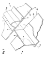
- eine schematische Darstellung zweier Verstei- fungselemente unterschiedlichen Profilquer- schnitts mit Schalenelementen;
- Fig. 2
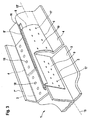
- ein Ausführungsbeispiel eines Kammabschnitt- Verbindungselementes einer erfindungsgemäßen Verbindungsanordnung;
- Fig. 3
- eine schematische perspektivische Darstellung eines ersten Ausführungsbeispiels einer erfin- dungsgemäßen Verbindungsanordnung mit dem Kamm- abschnitt-Verbindungselement nach
Fig. 2 für die Versteifungselemente nachFig. 1 ; - Fig. 4
- eine Seitenansicht in Längsrichtung der erfin- dungsgemäßen Verbindungsanordnung nach
Fig. 3 mit einem zweiten Fußabschnitt- Verbindungselement bei fluchtenden Mittellinien der Versteifungselemente; - Fig. 5
- die Ansicht nach
Fig. 4 bei seitlich versetzten Mittellinien der Versteifungselemente; - Fig. 6
- ein weiteres Ausführungsbeispiel des Kammab- schnitt-Verbindungselementes der erfindungsgemä- β en Verbindungsanordnung;
- Fig. 7
- eine schematische perspektivische Darstellung eines zweiten Ausführungsbeispiels der erfin- dungsgemäßen Verbindungsanordnung mit dem Kamm- abschnitt-Verbindungselement nach
Fig. 6 für die Versteifungselemente nachFig. 1 ; - Fig. 8
- ein noch weiteres Ausführungsbeispiel des Kamm- abschnitt-Verbindungselementes der erfindungsge- mäßen Verbindungsanordnung; und
- Fig. 9
- eine schematische perspektivische Darstellung eines dritten Ausführungsbeispiels der erfin- dungsgemäßen Verbindungsanordnung mit dem Kamm- abschnitt-Verbindungselement nach
Fig. 8 für die Versteifungselemente nachFig. 1 bei einem Ver- bindungsstoß von zwei Schalenelementen.
- Fig. 1
- a schematic representation of two stiffening elements of different profile cross-section with shell elements;
- Fig. 2
- an embodiment of a comb portion connecting element of a connecting arrangement according to the invention;
- Fig. 3
- a schematic perspective view of a first embodiment of an inventive connection arrangement with the comb portion connecting element according to
Fig. 2 for the stiffening elementsFig. 1 ; - Fig. 4
- a side view in the longitudinal direction of the inventive connection arrangement according to
Fig. 3 with a second Fußabschnitt- connecting element at aligned center lines of the stiffening elements; - Fig. 5
- the view after
Fig. 4 with laterally offset center lines of the stiffening elements; - Fig. 6
- a further embodiment of the comb portion connecting element of the inventive connection arrangement;
- Fig. 7
- a schematic perspective view of a second embodiment of the inventive connection arrangement with the comb portion connecting element according to
Fig. 6 for the stiffening elementsFig. 1 ; - Fig. 8
- a still further embodiment of the comb portion connecting element of the inventive connection arrangement; and
- Fig. 9
- a schematic perspective view of a third embodiment of the inventive connection arrangement with the comb portion connecting element according to
Fig. 8 for the stiffening elementsFig. 1 at a joint of two shell elements.
In den Figuren bezeichnen dieselben Bezugszeichen gleiche oder funktionsgleiche Komponenten, soweit nichts Gegenteiliges angegeben ist.In the figures, the same reference numerals designate the same or functionally identical components, unless indicated otherwise.
Die beiden Versteifungselemente 1, 2 sind hier am Rand einer Verbindungsstelle der Schalenelemente 20, 21 angeordnet. Die Schalenelemente 20, 21 weisen an dieser Verbindungsstelle Querstoßränder 23, 24 auf, an denen sie bei einer Verbindung aneinander anliegen. Diese Verbindung wird weiter unten erläutert.The two stiffening elements 1, 2 are arranged here at the edge of a connection point of the
Das erste Versteifungselement 1 ist hier als ein T-Stringer mit einem Fußabschnitt 3 und einem Kammabschnitt 5 ausgebildet. Im Gegensatz dazu weist das zweite Versteifungselement 2 einen Hohlprofilquerschnitt mit einem Kammabschnitt 6 und Fußabschnitt 4 auf und wird in dieser Ausführung auch als Omega-Stringer bezeichnet. Bei der Verbindung der Schalenelemente 20, 21 ist auch eine Verbindung der Versteifungselemente 1, 2 zur Kraftüberleitung und Versteifung notwendig. Die
Zur Verbindung der Versteifungselemente 1, 2 unterschiedlichen Profilquerschnitts ist es notwendig, sowohl die Fußabschnitte 3, 4 und die Kammabschnitte 5, 6 form- und kraftschlüssig mit einer Verbindungsanordnung zu verbinden. Hierzu weist ein Kammabschnitt-Verbindungselement 8, welches in
Das Kammabschnitt-Verbindungselement 8 weist eine flache Koppelfläche 9 auf, die zu dem Kammabschnitt 5 des ersten Versteifungselementes 1, des T-Stringers, korrespondiert. An einem in der
In
Zur Verbindung der Fußabschnitte 3 und 4 der Versteifungselemente 1, 2 sind Fußabschnitt-Verbindungselemente 7, 7' vorgesehen, von denen hier nur eins gezeigt ist. Es ist in diesem Beispiel als L-Profil ausgebildet und kann, wie auch das Kammabschnitt-Verbindungselement 8, 8' aus Metall und/oder Faserverbundwerkstoff hergestellt sein. Als ein Profil ist es vorteilhaft einfach als Stangenmaterial ablängbar. An seiner Unterseite liegt es auf den zu verbindenden Fußabschnitte 3, 4 der Versteifungselemente 1, 2 auf und ist mit diesen, zum Beispiel mittels Nieten, in Fußbefestigungen 18 fest verbunden. Um eine große Kraftübertragungsfläche zu erhalten, ist der Fußabschnitt 3 des T-Stringers 1 in diesem Beispiel verbreitert und an den Fußabschnitt des Omega-Stringers 2 angepasst. Die Verbreiterung an dieser Verbindungsstelle kann jedoch entsprechend der Ausführung vorher korrespondierend angepasst werden.To connect the foot sections 3 and 4 of the stiffening elements 1, 2 foot
In
Bei einem seitlichen Versatz der Mittelachsen 15, 15', den
Ein weiteres Ausführungsbeispiel des Kammabschnitt-Verbindungselementes 8 der erfindungsgemäßen Verbindungsanordnung ist in
In diesem Ausführungsbeispiel ist das Fußabschnitt-Verbindungselement 7 in Gestalt einer Fußkoppelfläche 14 mit dem Kammabschnitt-Verbindungselement 8 einstückig bzw. integral ausgebildet. Hier ist die Fußkoppelfläche 14 an einem Längsrand der Koppelprofilfläche 10 angebracht, welcher dem Längsverbindungsrand 12 gegenüber liegt. Das übrige Kammabschnitt-Verbindungselement 8 ist wie das der ersten Ausführung nach
Das spiegelbildliche integrale Kammabschnitt-Verbindungselement 8' ist leicht vorstellbar und in
Das integrale Kammabschnitt-Verbindungselement 8, 8' weist den Vorteil einer geringen Teilezahl gegenüber der ersten Ausführung auf. Bei einem seitlichen Versatz der Mittelachsen 15, 15' der Versteifungselemente 1, 2 sind hier Shims als Zwischenlagen zum Ausgleich zu verwenden.The integral comb
Es ist in einem noch weiteren Ausführungsbeispiel des KammabSchnitt-Verbindungselementes 8, welches
Diese Verbindungsstelle der Schalenelemente 20, 21 weist eine Querstoßlasche 22 auf, die nicht weiter erläutert wird. An dieser Querstoßlasche 22 liegen die Versteifungselemente 1, 2 von beiden Seiten an und weisen zwischen sich einen Zwischenraum auf, der von den verlängerten Koppelflächen 9' überbrückt ist. Die Kammabschnitt-Verbindungselemente 8, 8' sind wie oben erwähnt mit den korrespondierenden Kammabschnitten 5, 6 der Versteifungselemente 1, 2 verbunden. Die Fußkoppelflächen 14, 14' und die Fußabschnitt-Verbindungselemente 7, 7' sind mit den Fußabschnitten 3, 4 der Versteifungselemente 1, 2 wie oben angegeben in Fußbefestigungen 18 fest verbunden. Zusätzlich sind die Fußabschnitt-Verbindungselemente 7, 7' und die Fußkoppelflächen 14, 14' mit ihren Abschnitten, die sich über der Querstoßlasche 22 befinden, mit dieser Querstoßlasche 22 in Querstoßlaschenbefestigungen 19, zum Beispiel durch Nieten, auch fest verbunden, um so eine besonderes hohe Steifigkeit und Festigkeit der Verbindungsanordnung zu erzielen.This connection point of the
Obwohl die vorliegende Erfindung anhand bevorzugter Ausführungsbeispiele vorliegend beschrieben wurde, ist sie darauf nicht beschränkt, sondern auf vielfältige Weise kombinierbar und modifizierbar.Although the present invention has been described herein with reference to preferred embodiments, it is not limited thereto, but combinable and modifiable in a variety of ways.
Beispielsweise kann sich die Koppelfläche 9 des Kammabschnitt-Verbindungselementes 8, 8' weiter hinter die Koppelprofilfläche 10 erstrecken. Auch diese kann sich weiter vor die Koppelfläche 9 ausdehnen, wodurch eine höhere Festigkeit und Steifigkeit erreichbar ist.For example, the
Die mit der erfindungsgemäßen Verbindungsanordnung zu verbindenden Versteifungselemente 1, 2 können an einer beliebigen Stelle auf einem Schalenelement 20, 21, so auch an einer Verbindungsstelle der Schalenelemente 20, 21 mit oder ohne Querstoßlasche 22 angeordnet sein.The stiffening elements 1, 2 to be connected with the connection arrangement according to the invention can be arranged at any point on a
Es sind auch andere Profilformen der Versteifungselemente 1, 2 möglich.There are also other profile shapes of the stiffening elements 1, 2 possible.
Bei einer Verbindungsanordnung zum Verbinden zweier Versteifungselemente 1, 2 eines Luft- oder Raumfahrzeugs, wobei die Versteifungselemente 1, 2 unterschiedliche Querschnittsprofile mit jeweils zumindest einem Fußabschnitt 3, 4 und zumindest einem Kammabschnitt 5, 6 aufweisen, ist mindestens ein Fußabschnitt-Verbindungselement 7, 7', welches an einer Seite an die geometrische Form des Fußabschnitts 3 des ersten Versteifungselementes 1 und an der gegenüberliegenden Seite an die geometrische Form des Fußabschnitts 4 des zweiten Versteifungselementes 2 anpassbar und an diesen jeweils fest verbindbar; und mindestens ein Kammabschnitt-Verbindungselement 8, 8', welches an einer Seite an die geometrische Form des Kammabschnitts 5 des ersten Versteifungselementes 1 und an der gegenüberliegenden Seite an die geometrische Form des Kammabschnitts 6 des zweiten Versteifungselementes 2 anpassbar und an diesen jeweils fest verbindbar. Ein Schalenbauteil mit zumindest zwei Versteifungselementen 1, 2 unterschiedlichen Profilquerschnitts weist die Verbindungsanordnung auf.In a connection arrangement for connecting two stiffening elements 1, 2 of an aircraft or spacecraft, the stiffening elements 1, 2 having different cross-sectional profiles, each with at least one foot section 3, 4 and at least one
- 1, 21, 2
- Versteifungselement (T-Stringer, Omega- Stringer)Stiffening element (T-Stringer, Omega Stringer)
- 3, 43, 4
- Fußabschnittfoot section
- 5, 65, 6
- Kammabschnittcomb section
- 7, 7'7, 7 '
- Fußabschnitt-VerbindungselementFoot portion connecting element
- 8, 8'8, 8 '
- Kammabschnitt-VerbindungselementComb portion connecting element
- 99
- Koppelflächecoupling surface
- 1010
- KoppelprofilflächeCoupling profile surface
- 1111
- Längsverbindungsrand KoppelflächeLongitudinal connecting edge coupling surface
- 1212
- Längsverbindungsrand KoppelprofilflächeLongitudinal connecting edge coupling profile surface
- 1313
- Verbindungsstegconnecting web
- 1414
- FußkoppeltlächeFußkoppeltläche
- 15, 15'15, 15 '
- Mittelachsecentral axis
- 1616
- Ausnehmungrecess
- 1717
- Kammbefestigungcomb attachment
- 1818
- FußbefestigungFoot
- 1919
- QuerstoßlaschenbefestigungCross butt strap attachment
- 20, 2120, 21
- Schalenelementshell element
- 2222
- QuerstoßlascheTransverse butt strap
- 23, 2423, 24
- QuerstoßrandTransverse joint edge
Claims (17)
- Connecting arrangement for connecting two reinforcing elements (1, 2) of an aircraft or spacecraft, wherein the reinforcing elements (1, 2) have different cross-sectional profiles with in each case at least one foot portion (3, 4) and at least one comb portion (5, 6), the connecting arrangement comprising:at least one foot portion connecting element (7, 7') which on one side can be adapted to the geometric shape of the foot portion (3) of the first reinforcing element (1) and on the opposite side can be adapted to the geometric shape of the foot portion (4) of the second reinforcing element (2) and can be connected rigidly thereto in each case; andat least one comb portion connecting element (8, 8') which on one side can be adapted to the geometric shape of the comb portion (5) of the first reinforcing element (1) and on the opposite side can be adapted to the geometric shape of the comb portion (6) of the second reinforcing element (2) and can be connected rigidly thereto in each case.
- Connecting arrangement according to claim 1, characterised in that in each case a foot portion connecting element (7, 7') and a comb portion connecting element (8, 8') can be connected on both sides of the comb portions (5, 6) of the reinforcing elements (1, 2) to be connected on the corresponding foot portions (3, 4) and comb portions (5, 6).
- Connecting arrangement according to either claim 1 or claim 2, characterised in that the comb portion connecting element (8, 8') has a coupling surface (9) for connecting to the first reinforcing element (1) and has a coupling profiled surface (10) for connecting to the second reinforcing element (2), the coupling surface (9) and the coupling profiled surface (10) being connected along longitudinal connecting edges (11, 12) by a connecting web (13).
- Connecting arrangement according to at least one of the preceding claims, characterised in that the foot portion connecting element (7, 7') has an L-shaped profile.
- Connecting arrangement according to at least one of the preceding claims, characterised in that the comb portion connecting element (8, 8') for connecting a reinforcing element (1) is adapted in the form of a T-stringer and for connecting a reinforcing element (1) is adapted in the form of an omega stringer.
- Connecting arrangement according to at least one of the preceding claims, characterised in that the foot portion connecting element (7, 7') and the comb portion connecting element (8, 8') are formed from a metal and/or a composite material.
- Connecting arrangement according to at least one of the preceding claims, characterised in that the foot portion connecting element (7, 7') and the comb portion connecting element (8, 8') are configured such that they can be connected to the reinforcing elements (1, 2) to be connected by rivet joints.
- Connecting arrangement according to at least one of the preceding claims, characterised in that the comb portion connecting element (8, 8') is configured integrally with a foot portion connecting element (7, 7').
- Connecting arrangement according to claim 8, characterised in that the foot portion connecting element (7, 7') is configured integrally as a foot coupling surface (14) with the coupling profiled surface (10) and/or with the coupling surface (9) of the comb portion connecting element (8, 8').
- Shell component of an aircraft or spacecraft, with at least two reinforcing elements (1, 2) of different cross-sectional profiles, wherein the reinforcing elements (1, 2) are connected in their longitudinal direction by a connecting arrangement according to at least one of the preceding claims, or wherein the reinforcing elements (1 , 2) are connected in their longitudinal direction, being laterally offset, by a connecting arrangement according to at least one of claims 1 to 7, or are connected by a connecting arrangement according to at least one of claims 1 to 9 with additional shims for a tolerance compensation.
- Shell component according to claim 10, characterised in that the shell component has at least two connected shell elements (20, 21).
- Shell component according to claim 11, characterised in that the at least two connected shell elements (20, 21) are connected by a transverse butt strap (22).
- Shell component according to at least one of claims 10 to 12, characterised in that one reinforcing element (1) is a T-stringer and in that the other reinforcing element (2) is an omega stringer.
- Shell component according to at least one of claims 10 to 13, characterised in that at least one foot portion (3, 4) of the reinforcing elements (1, 2) is widened at the connection point of the reinforcing elements (1, 2).
- Shell component according to either claim 13 or claim 14, characterised in that the reinforcing element (2) configured as an omega stringer has a recess (16) running in the longitudinal direction in its upper side in the region of the connecting arrangement.
- Shell component according to at least one of claims 10 to 15, characterised in that the comb portion connecting elements (8, 8') are configured to be mirror-inverted.
- Shell component according to at least one of claims 12 to 16, characterised in that in the case of reinforcing elements (1, 2) which have different profile cross sections and are arranged such that they are connected by the connecting arrangement at the connection point of the shell elements (20, 21), the foot portion connecting elements (7, 7') and/or foot coupling surfaces (14) of the comb portion connecting elements (8, 8') of the connecting arrangement are connected to the transverse butt strap (22).
Applications Claiming Priority (3)
| Application Number | Priority Date | Filing Date | Title |
|---|---|---|---|
| US6301208P | 2008-01-30 | 2008-01-30 | |
| DE102008006834A DE102008006834A1 (en) | 2008-01-30 | 2008-01-30 | Connecting arrangement for connecting two stiffening elements of different cross-sectional profile for an aircraft or spacecraft, and a shell component |
| PCT/EP2008/067214 WO2009095133A2 (en) | 2008-01-30 | 2008-12-10 | Connecting arrangement for joining two stiffening elements having different cross-sectional profiles for an aircraft or spacecraft, and shell component |
Publications (2)
| Publication Number | Publication Date |
|---|---|
| EP2238021A2 EP2238021A2 (en) | 2010-10-13 |
| EP2238021B1 true EP2238021B1 (en) | 2011-04-13 |
Family
ID=40913325
Family Applications (1)
| Application Number | Title | Priority Date | Filing Date |
|---|---|---|---|
| EP08871637A Not-in-force EP2238021B1 (en) | 2008-01-30 | 2008-12-10 | Connecting arrangement for joining two stiffening elements having different cross-sectional profiles for an aircraft or spacecraft, and shell component |
Country Status (10)
| Country | Link |
|---|---|
| US (1) | US8528865B2 (en) |
| EP (1) | EP2238021B1 (en) |
| JP (1) | JP2011510859A (en) |
| CN (1) | CN101932506B (en) |
| AT (1) | ATE505398T1 (en) |
| BR (1) | BRPI0822041A2 (en) |
| CA (1) | CA2712062A1 (en) |
| DE (2) | DE102008006834A1 (en) |
| RU (1) | RU2482017C2 (en) |
| WO (1) | WO2009095133A2 (en) |
Families Citing this family (12)
| Publication number | Priority date | Publication date | Assignee | Title |
|---|---|---|---|---|
| DE102008012252B4 (en) * | 2008-03-03 | 2014-07-31 | Airbus Operations Gmbh | Composite as well as aircraft or spacecraft with such a composite |
| ES2384250B1 (en) * | 2009-09-30 | 2013-05-16 | Airbus Operations, S.L. | UNION OF AIRCRAFT STRUCTURAL ELEMENTS. |
| DE102010042970A1 (en) * | 2010-05-12 | 2011-11-17 | Airbus Operations Gmbh | Structural component with improved conductivity and mechanical strength and method for its production |
| ES2398985B1 (en) * | 2011-03-14 | 2014-02-14 | Airbus Operations S.L. | LOAD TRANSFER DEVICES IN THE TERMINATION OF A LARGUERILLO. |
| FR2984844B1 (en) * | 2011-12-21 | 2014-02-28 | Airbus Operations Sas | ANTI-SPEED AIRCRAFT FUSELAGE STRUCTURE ELEMENT |
| FR2993856B1 (en) * | 2012-07-30 | 2015-09-18 | Airbus Operations Sas | AIRCRAFT FUSELAGE STRUCTURE ELEMENT HAVING AN EVOLVING SECTION |
| FR3007735B1 (en) * | 2013-06-28 | 2015-08-07 | Airbus Operations Sas | CONNECTING AN AIRCRAFT FUSELAGE MEMBER AND A FRAME BY A SPACER AND A THRUST |
| US9656319B2 (en) * | 2013-11-13 | 2017-05-23 | The Boeing Company | Positioning system for electromagnetic riveting |
| EP2907743A1 (en) * | 2014-02-13 | 2015-08-19 | Airbus Operations GmbH | Stiffening element, method for coupling the same, and shell component for an aircraft or spacecraft |
| US9724848B2 (en) * | 2014-07-03 | 2017-08-08 | The Boeing Company | Collapsible, coiled mandrel |
| US11198497B2 (en) | 2019-06-19 | 2021-12-14 | The Boeing Company | Splice fittings that are affixed to stringers via web-installed fasteners |
| CN113290117B (en) * | 2021-05-21 | 2022-09-09 | 青岛中天鹏锻压制造有限公司 | Plastic forming method and mould for traction beam web of rail transit vehicle |
Family Cites Families (28)
| Publication number | Priority date | Publication date | Assignee | Title |
|---|---|---|---|---|
| US1854330A (en) * | 1928-12-20 | 1932-04-19 | Nieuportastra Sa | Metallic construction of aircraft |
| US2383634A (en) * | 1943-02-20 | 1945-08-28 | Budd Edward G Mfg Co | Main frame structure for airfoils or the like |
| US2382358A (en) * | 1944-02-03 | 1945-08-14 | Budd Edward G Mfg Co | Stressed skin airfoil joint |
| US3004645A (en) * | 1959-08-27 | 1961-10-17 | Jr George E Moul | Aerodynamic surface attaching structure |
| US3827661A (en) * | 1972-07-26 | 1974-08-06 | Ryson Aviat Corp | Aircraft wing structure and method of assembly |
| US4256790A (en) * | 1978-01-19 | 1981-03-17 | Rockwell International Corporation | Reinforced composite structure and method of fabrication thereof |
| SU967017A1 (en) * | 1980-07-14 | 1991-10-30 | Предприятие П/Я В-2739 | Stringer of aircraft panel |
| US4813202A (en) * | 1987-05-22 | 1989-03-21 | Grumman Aerospace Corporation | Structural members connected by interdigitating portions |
| JPH05286493A (en) * | 1992-04-08 | 1993-11-02 | Honda Motor Co Ltd | Fuselage structure of aircraft |
| US5518208A (en) * | 1993-12-28 | 1996-05-21 | The Boeing Company | Optimum aircraft body frame to body skin shear tie installation pattern for body skin/stringer circumferential splices |
| US6375120B1 (en) * | 1997-07-14 | 2002-04-23 | Jason M. Wolnek | Method and apparatus for building a metal/composite hybrid airplane component |
| US6105902A (en) * | 1997-07-15 | 2000-08-22 | Mcdonnell Douglas Corporation | Aircraft fuselage and method of forming same |
| DE19844035C1 (en) * | 1998-09-25 | 1999-11-25 | Daimler Chrysler Aerospace | Shell component for an aircraft, and method for its production |
| RU2179136C2 (en) * | 1999-06-21 | 2002-02-10 | Комсомольское-на-Амуре авиационное производственное объединение | Method of assembly of flying vehicle units |
| US7681835B2 (en) * | 1999-11-18 | 2010-03-23 | Rocky Mountain Composites, Inc. | Single piece co-cure composite wing |
| DE10007995C2 (en) * | 2000-02-22 | 2002-03-07 | Airbus Gmbh | Structural component, in particular for an aircraft and method for producing a structural component |
| DE10031510A1 (en) * | 2000-06-28 | 2002-01-17 | Airbus Gmbh | Structural component for an aircraft |
| US7205066B1 (en) * | 2002-05-23 | 2007-04-17 | Rohr, Inc. | Structural element with rib-receiving member |
| US8585313B2 (en) * | 2005-01-27 | 2013-11-19 | Edsal Manufacturing Co., Inc. | Post coupler |
| US7325771B2 (en) * | 2004-09-23 | 2008-02-05 | The Boeing Company | Splice joints for composite aircraft fuselages and other structures |
| US7530531B2 (en) * | 2004-10-04 | 2009-05-12 | The Boeing Company | Apparatus and methods for installing an aircraft window panel |
| US7555873B2 (en) * | 2004-11-30 | 2009-07-07 | The Boeing Company | Self-locating feature for a pi-joint assembly |
| US7410120B2 (en) * | 2005-01-21 | 2008-08-12 | The Boeing Company | Control surface assemblies with torque tube base |
| DE102006008455A1 (en) | 2006-02-18 | 2007-10-18 | Emil Bucher Gmbh & Co.Kg Modell-Und Maschinenbau | Method for applying adhesive to stringer used in making airfoils comprises applying tape with adhesive, support and removable protective layers to flanges, protective layer being removed and tape cut to fit before it is pressed on |
| IL184216A0 (en) | 2007-06-25 | 2008-01-06 | Rafael Advanced Defense Sys | Two-stage airbag inflation system with pyrotechnic delay |
| DE102007029500B4 (en) * | 2007-06-25 | 2013-02-14 | Airbus Operations Gmbh | Method for coupling stiffening profile elements and structural component |
| DE102007033868B4 (en) * | 2007-07-20 | 2013-01-31 | Airbus Operations Gmbh | Profile with at least one hollow profile cross-section |
| DE102008002117B4 (en) | 2008-05-30 | 2013-10-31 | Airbus Operations Gmbh | Composite and structure |
-
2008
- 2008-01-30 DE DE102008006834A patent/DE102008006834A1/en not_active Withdrawn
- 2008-12-10 AT AT08871637T patent/ATE505398T1/en active
- 2008-12-10 BR BRPI0822041A patent/BRPI0822041A2/en not_active IP Right Cessation
- 2008-12-10 CA CA2712062A patent/CA2712062A1/en not_active Abandoned
- 2008-12-10 CN CN200880125939.3A patent/CN101932506B/en not_active Expired - Fee Related
- 2008-12-10 WO PCT/EP2008/067214 patent/WO2009095133A2/en active Application Filing
- 2008-12-10 JP JP2010544603A patent/JP2011510859A/en active Pending
- 2008-12-10 EP EP08871637A patent/EP2238021B1/en not_active Not-in-force
- 2008-12-10 DE DE502008003231T patent/DE502008003231D1/en active Active
- 2008-12-10 RU RU2010128137/11A patent/RU2482017C2/en not_active IP Right Cessation
-
2010
- 2010-07-19 US US12/838,950 patent/US8528865B2/en active Active
Also Published As
| Publication number | Publication date |
|---|---|
| CA2712062A1 (en) | 2009-08-06 |
| WO2009095133A2 (en) | 2009-08-06 |
| US20110011980A1 (en) | 2011-01-20 |
| RU2482017C2 (en) | 2013-05-20 |
| ATE505398T1 (en) | 2011-04-15 |
| JP2011510859A (en) | 2011-04-07 |
| EP2238021A2 (en) | 2010-10-13 |
| WO2009095133A3 (en) | 2009-10-22 |
| DE502008003231D1 (en) | 2011-05-26 |
| DE102008006834A1 (en) | 2009-10-15 |
| CN101932506A (en) | 2010-12-29 |
| BRPI0822041A2 (en) | 2019-09-24 |
| CN101932506B (en) | 2014-06-11 |
| US8528865B2 (en) | 2013-09-10 |
| RU2010128137A (en) | 2012-01-20 |
Similar Documents
| Publication | Publication Date | Title |
|---|---|---|
| EP2238021B1 (en) | Connecting arrangement for joining two stiffening elements having different cross-sectional profiles for an aircraft or spacecraft, and shell component | |
| EP2247496B1 (en) | Interconnection and aircraft or spacecraft having such an interconnection | |
| EP2279073B1 (en) | Composite and structure, particularly in the aerospace sector | |
| EP3180243B1 (en) | Control surface element for an airplane | |
| EP2813134B1 (en) | Rod belt for rod belt conveyors of agricultural machines | |
| EP2170696B1 (en) | Profile comprising at least one hollow profile section | |
| EP2398636A1 (en) | Method for producing a shell body and corresponding body | |
| DE102012022876A1 (en) | Reinforcing element for amplifying longitudinal and lateral surfaces of multi-chamber hollow profile i.e. car body, has arm sections inserted into hollow section interior over insertion opening formed on side surface of hollow section | |
| DE102009056998B4 (en) | Stiffening structure for fabrics and aircraft | |
| DE102004025377B4 (en) | Window frame for aircraft | |
| DE102019111836B4 (en) | Profile component for reinforcing component structures, component structure and manufacturing process for this | |
| DE102009031838A1 (en) | Support structure for motor vehicle body, has component connected with another component by mechanical joining element, where components are formed as support parts and include respective flange areas | |
| DE102009056997B4 (en) | Stiffening structure and method for producing such a structure | |
| EP3456888B1 (en) | Excavator boom and excavator | |
| EP2361195B1 (en) | Shell component for aerospace vehicle | |
| DE102008047793B4 (en) | Load introduction element | |
| EP3376024A1 (en) | Divisible wind turbine rotor blade with bolted connection | |
| EP2474409B1 (en) | Connection between a basis component and a fibre reinforced multilayered composite component | |
| DE102008018772A1 (en) | Locking device for torque-proof locking of drive part of internal combustion engine, has slide guided into connecting rod, where drive part is fixed to camshaft and output part of camshaft adjuster | |
| DE102008038426B4 (en) | Angled lever on a shell component, in particular for the Einstellwinkelsteuerung a rotor blade, and method for fixing such an angled lever | |
| EP2602398B1 (en) | Wooden frame | |
| DE102018108402B4 (en) | Plug-in connector for a rim ring, in particular for bicycles | |
| DE102009011022A1 (en) | Connection arrangement i.e. repair connection arrangement, for connecting carrier with hollow chambers of body of passenger car, has connection element inserted into chambers of carrier sections, where one of sections exhibit carrier parts | |
| DE19858435C1 (en) | Cover skin-bridge structure | |
| EP2891604A1 (en) | Mast for sailing vessels |
Legal Events
| Date | Code | Title | Description |
|---|---|---|---|
| PUAI | Public reference made under article 153(3) epc to a published international application that has entered the european phase |
Free format text: ORIGINAL CODE: 0009012 |
|
| 17P | Request for examination filed |
Effective date: 20100701 |
|
| AK | Designated contracting states |
Kind code of ref document: A2 Designated state(s): AT BE BG CH CY CZ DE DK EE ES FI FR GB GR HR HU IE IS IT LI LT LU LV MC MT NL NO PL PT RO SE SI SK TR |
|
| AX | Request for extension of the european patent |
Extension state: AL BA MK RS |
|
| RIN1 | Information on inventor provided before grant (corrected) |
Inventor name: REYE, VOLKER Inventor name: LENGSFELD, HAUKE Inventor name: TACKE, STEFAN |
|
| GRAP | Despatch of communication of intention to grant a patent |
Free format text: ORIGINAL CODE: EPIDOSNIGR1 |
|
| GRAS | Grant fee paid |
Free format text: ORIGINAL CODE: EPIDOSNIGR3 |
|
| GRAA | (expected) grant |
Free format text: ORIGINAL CODE: 0009210 |
|
| AK | Designated contracting states |
Kind code of ref document: B1 Designated state(s): AT BE BG CH CY CZ DE DK EE ES FI FR GB GR HR HU IE IS IT LI LT LU LV MC MT NL NO PL PT RO SE SI SK TR |
|
| REG | Reference to a national code |
Ref country code: GB Ref legal event code: FG4D Free format text: NOT ENGLISH |
|
| REG | Reference to a national code |
Ref country code: CH Ref legal event code: EP |
|
| REG | Reference to a national code |
Ref country code: IE Ref legal event code: FG4D Free format text: LANGUAGE OF EP DOCUMENT: GERMAN |
|
| REF | Corresponds to: |
Ref document number: 502008003231 Country of ref document: DE Date of ref document: 20110526 Kind code of ref document: P |
|
| REG | Reference to a national code |
Ref country code: DE Ref legal event code: R096 Ref document number: 502008003231 Country of ref document: DE Effective date: 20110526 |
|
| REG | Reference to a national code |
Ref country code: NL Ref legal event code: VDEP Effective date: 20110413 |
|
| LTIE | Lt: invalidation of european patent or patent extension |
Effective date: 20110413 |
|
| PG25 | Lapsed in a contracting state [announced via postgrant information from national office to epo] |
Ref country code: PT Free format text: LAPSE BECAUSE OF FAILURE TO SUBMIT A TRANSLATION OF THE DESCRIPTION OR TO PAY THE FEE WITHIN THE PRESCRIBED TIME-LIMIT Effective date: 20110816 Ref country code: NO Free format text: LAPSE BECAUSE OF FAILURE TO SUBMIT A TRANSLATION OF THE DESCRIPTION OR TO PAY THE FEE WITHIN THE PRESCRIBED TIME-LIMIT Effective date: 20110713 Ref country code: LT Free format text: LAPSE BECAUSE OF FAILURE TO SUBMIT A TRANSLATION OF THE DESCRIPTION OR TO PAY THE FEE WITHIN THE PRESCRIBED TIME-LIMIT Effective date: 20110413 Ref country code: SE Free format text: LAPSE BECAUSE OF FAILURE TO SUBMIT A TRANSLATION OF THE DESCRIPTION OR TO PAY THE FEE WITHIN THE PRESCRIBED TIME-LIMIT Effective date: 20110413 Ref country code: HR Free format text: LAPSE BECAUSE OF FAILURE TO SUBMIT A TRANSLATION OF THE DESCRIPTION OR TO PAY THE FEE WITHIN THE PRESCRIBED TIME-LIMIT Effective date: 20110413 |
|
| REG | Reference to a national code |
Ref country code: IE Ref legal event code: FD4D |
|
| PG25 | Lapsed in a contracting state [announced via postgrant information from national office to epo] |
Ref country code: CY Free format text: LAPSE BECAUSE OF FAILURE TO SUBMIT A TRANSLATION OF THE DESCRIPTION OR TO PAY THE FEE WITHIN THE PRESCRIBED TIME-LIMIT Effective date: 20110413 Ref country code: IS Free format text: LAPSE BECAUSE OF FAILURE TO SUBMIT A TRANSLATION OF THE DESCRIPTION OR TO PAY THE FEE WITHIN THE PRESCRIBED TIME-LIMIT Effective date: 20110813 Ref country code: FI Free format text: LAPSE BECAUSE OF FAILURE TO SUBMIT A TRANSLATION OF THE DESCRIPTION OR TO PAY THE FEE WITHIN THE PRESCRIBED TIME-LIMIT Effective date: 20110413 Ref country code: SI Free format text: LAPSE BECAUSE OF FAILURE TO SUBMIT A TRANSLATION OF THE DESCRIPTION OR TO PAY THE FEE WITHIN THE PRESCRIBED TIME-LIMIT Effective date: 20110413 Ref country code: ES Free format text: LAPSE BECAUSE OF FAILURE TO SUBMIT A TRANSLATION OF THE DESCRIPTION OR TO PAY THE FEE WITHIN THE PRESCRIBED TIME-LIMIT Effective date: 20110724 Ref country code: LV Free format text: LAPSE BECAUSE OF FAILURE TO SUBMIT A TRANSLATION OF THE DESCRIPTION OR TO PAY THE FEE WITHIN THE PRESCRIBED TIME-LIMIT Effective date: 20110413 Ref country code: GR Free format text: LAPSE BECAUSE OF FAILURE TO SUBMIT A TRANSLATION OF THE DESCRIPTION OR TO PAY THE FEE WITHIN THE PRESCRIBED TIME-LIMIT Effective date: 20110714 |
|
| PG25 | Lapsed in a contracting state [announced via postgrant information from national office to epo] |
Ref country code: NL Free format text: LAPSE BECAUSE OF FAILURE TO SUBMIT A TRANSLATION OF THE DESCRIPTION OR TO PAY THE FEE WITHIN THE PRESCRIBED TIME-LIMIT Effective date: 20110413 |
|
| PG25 | Lapsed in a contracting state [announced via postgrant information from national office to epo] |
Ref country code: IE Free format text: LAPSE BECAUSE OF FAILURE TO SUBMIT A TRANSLATION OF THE DESCRIPTION OR TO PAY THE FEE WITHIN THE PRESCRIBED TIME-LIMIT Effective date: 20110413 Ref country code: EE Free format text: LAPSE BECAUSE OF FAILURE TO SUBMIT A TRANSLATION OF THE DESCRIPTION OR TO PAY THE FEE WITHIN THE PRESCRIBED TIME-LIMIT Effective date: 20110413 Ref country code: CZ Free format text: LAPSE BECAUSE OF FAILURE TO SUBMIT A TRANSLATION OF THE DESCRIPTION OR TO PAY THE FEE WITHIN THE PRESCRIBED TIME-LIMIT Effective date: 20110413 |
|
| PLBE | No opposition filed within time limit |
Free format text: ORIGINAL CODE: 0009261 |
|
| STAA | Information on the status of an ep patent application or granted ep patent |
Free format text: STATUS: NO OPPOSITION FILED WITHIN TIME LIMIT |
|
| PG25 | Lapsed in a contracting state [announced via postgrant information from national office to epo] |
Ref country code: RO Free format text: LAPSE BECAUSE OF FAILURE TO SUBMIT A TRANSLATION OF THE DESCRIPTION OR TO PAY THE FEE WITHIN THE PRESCRIBED TIME-LIMIT Effective date: 20110413 Ref country code: SK Free format text: LAPSE BECAUSE OF FAILURE TO SUBMIT A TRANSLATION OF THE DESCRIPTION OR TO PAY THE FEE WITHIN THE PRESCRIBED TIME-LIMIT Effective date: 20110413 Ref country code: DK Free format text: LAPSE BECAUSE OF FAILURE TO SUBMIT A TRANSLATION OF THE DESCRIPTION OR TO PAY THE FEE WITHIN THE PRESCRIBED TIME-LIMIT Effective date: 20110413 Ref country code: PL Free format text: LAPSE BECAUSE OF FAILURE TO SUBMIT A TRANSLATION OF THE DESCRIPTION OR TO PAY THE FEE WITHIN THE PRESCRIBED TIME-LIMIT Effective date: 20110413 |
|
| 26N | No opposition filed |
Effective date: 20120116 |
|
| REG | Reference to a national code |
Ref country code: DE Ref legal event code: R097 Ref document number: 502008003231 Country of ref document: DE Effective date: 20120116 |
|
| BERE | Be: lapsed |
Owner name: AIRBUS OPERATIONS G.M.B.H. Effective date: 20111231 |
|
| PG25 | Lapsed in a contracting state [announced via postgrant information from national office to epo] |
Ref country code: MC Free format text: LAPSE BECAUSE OF NON-PAYMENT OF DUE FEES Effective date: 20111231 |
|
| PG25 | Lapsed in a contracting state [announced via postgrant information from national office to epo] |
Ref country code: BE Free format text: LAPSE BECAUSE OF NON-PAYMENT OF DUE FEES Effective date: 20111231 |
|
| PG25 | Lapsed in a contracting state [announced via postgrant information from national office to epo] |
Ref country code: MT Free format text: LAPSE BECAUSE OF FAILURE TO SUBMIT A TRANSLATION OF THE DESCRIPTION OR TO PAY THE FEE WITHIN THE PRESCRIBED TIME-LIMIT Effective date: 20110413 |
|
| PG25 | Lapsed in a contracting state [announced via postgrant information from national office to epo] |
Ref country code: LU Free format text: LAPSE BECAUSE OF NON-PAYMENT OF DUE FEES Effective date: 20111210 |
|
| PG25 | Lapsed in a contracting state [announced via postgrant information from national office to epo] |
Ref country code: BG Free format text: LAPSE BECAUSE OF FAILURE TO SUBMIT A TRANSLATION OF THE DESCRIPTION OR TO PAY THE FEE WITHIN THE PRESCRIBED TIME-LIMIT Effective date: 20110713 |
|
| REG | Reference to a national code |
Ref country code: CH Ref legal event code: PL |
|
| PG25 | Lapsed in a contracting state [announced via postgrant information from national office to epo] |
Ref country code: TR Free format text: LAPSE BECAUSE OF FAILURE TO SUBMIT A TRANSLATION OF THE DESCRIPTION OR TO PAY THE FEE WITHIN THE PRESCRIBED TIME-LIMIT Effective date: 20110413 |
|
| PG25 | Lapsed in a contracting state [announced via postgrant information from national office to epo] |
Ref country code: HU Free format text: LAPSE BECAUSE OF FAILURE TO SUBMIT A TRANSLATION OF THE DESCRIPTION OR TO PAY THE FEE WITHIN THE PRESCRIBED TIME-LIMIT Effective date: 20110413 Ref country code: CH Free format text: LAPSE BECAUSE OF NON-PAYMENT OF DUE FEES Effective date: 20121231 Ref country code: LI Free format text: LAPSE BECAUSE OF NON-PAYMENT OF DUE FEES Effective date: 20121231 |
|
| REG | Reference to a national code |
Ref country code: AT Ref legal event code: MM01 Ref document number: 505398 Country of ref document: AT Kind code of ref document: T Effective date: 20131210 |
|
| PG25 | Lapsed in a contracting state [announced via postgrant information from national office to epo] |
Ref country code: AT Free format text: LAPSE BECAUSE OF NON-PAYMENT OF DUE FEES Effective date: 20131210 |
|
| REG | Reference to a national code |
Ref country code: FR Ref legal event code: PLFP Year of fee payment: 8 |
|
| REG | Reference to a national code |
Ref country code: FR Ref legal event code: PLFP Year of fee payment: 9 |
|
| PGFP | Annual fee paid to national office [announced via postgrant information from national office to epo] |
Ref country code: DE Payment date: 20161213 Year of fee payment: 9 Ref country code: GB Payment date: 20161222 Year of fee payment: 9 |
|
| PGFP | Annual fee paid to national office [announced via postgrant information from national office to epo] |
Ref country code: FR Payment date: 20161222 Year of fee payment: 9 |
|
| PGFP | Annual fee paid to national office [announced via postgrant information from national office to epo] |
Ref country code: IT Payment date: 20161223 Year of fee payment: 9 |
|
| REG | Reference to a national code |
Ref country code: DE Ref legal event code: R119 Ref document number: 502008003231 Country of ref document: DE |
|
| GBPC | Gb: european patent ceased through non-payment of renewal fee |
Effective date: 20171210 |
|
| REG | Reference to a national code |
Ref country code: FR Ref legal event code: ST Effective date: 20180831 |
|
| PG25 | Lapsed in a contracting state [announced via postgrant information from national office to epo] |
Ref country code: DE Free format text: LAPSE BECAUSE OF NON-PAYMENT OF DUE FEES Effective date: 20180703 Ref country code: FR Free format text: LAPSE BECAUSE OF NON-PAYMENT OF DUE FEES Effective date: 20180102 Ref country code: IT Free format text: LAPSE BECAUSE OF NON-PAYMENT OF DUE FEES Effective date: 20171210 |
|
| PG25 | Lapsed in a contracting state [announced via postgrant information from national office to epo] |
Ref country code: GB Free format text: LAPSE BECAUSE OF NON-PAYMENT OF DUE FEES Effective date: 20171210 |