RU2482017C2 - Connector for jointing two reinforcing elements with different profiles of cross-section for aircraft or spacecraft and skin component - Google Patents
Connector for jointing two reinforcing elements with different profiles of cross-section for aircraft or spacecraft and skin component Download PDFInfo
- Publication number
- RU2482017C2 RU2482017C2 RU2010128137/11A RU2010128137A RU2482017C2 RU 2482017 C2 RU2482017 C2 RU 2482017C2 RU 2010128137/11 A RU2010128137/11 A RU 2010128137/11A RU 2010128137 A RU2010128137 A RU 2010128137A RU 2482017 C2 RU2482017 C2 RU 2482017C2
- Authority
- RU
- Russia
- Prior art keywords
- base
- reinforcing
- elements
- reinforcing elements
- head
- Prior art date
Links
- 230000003014 reinforcing effect Effects 0.000 title claims abstract description 101
- 239000002131 composite material Substances 0.000 claims description 8
- 238000006073 displacement reaction Methods 0.000 claims description 4
- 239000007769 metal material Substances 0.000 claims 1
- 230000003247 decreasing effect Effects 0.000 abstract 1
- 230000000694 effects Effects 0.000 abstract 1
- 125000006850 spacer group Chemical group 0.000 abstract 1
- 239000000126 substance Substances 0.000 abstract 1
- 238000000034 method Methods 0.000 description 7
- 238000004519 manufacturing process Methods 0.000 description 6
- 239000002184 metal Substances 0.000 description 5
- 239000000835 fiber Substances 0.000 description 4
- 238000007689 inspection Methods 0.000 description 4
- 229920000049 Carbon (fiber) Polymers 0.000 description 3
- 239000004917 carbon fiber Substances 0.000 description 3
- VNWKTOKETHGBQD-UHFFFAOYSA-N methane Chemical compound C VNWKTOKETHGBQD-UHFFFAOYSA-N 0.000 description 3
- 238000010276 construction Methods 0.000 description 2
- -1 for example Substances 0.000 description 2
- 238000002347 injection Methods 0.000 description 2
- 239000007924 injection Substances 0.000 description 2
- 239000000047 product Substances 0.000 description 2
- 239000011265 semifinished product Substances 0.000 description 2
- 238000013459 approach Methods 0.000 description 1
- 239000004918 carbon fiber reinforced polymer Substances 0.000 description 1
- 238000005253 cladding Methods 0.000 description 1
- 150000001875 compounds Chemical class 0.000 description 1
- 238000005336 cracking Methods 0.000 description 1
- 230000001419 dependent effect Effects 0.000 description 1
- 239000003822 epoxy resin Substances 0.000 description 1
- 238000012423 maintenance Methods 0.000 description 1
- 239000000463 material Substances 0.000 description 1
- 239000011159 matrix material Substances 0.000 description 1
- 229920000647 polyepoxide Polymers 0.000 description 1
- 230000003068 static effect Effects 0.000 description 1
Images
Classifications
-
- B—PERFORMING OPERATIONS; TRANSPORTING
- B64—AIRCRAFT; AVIATION; COSMONAUTICS
- B64C—AEROPLANES; HELICOPTERS
- B64C1/00—Fuselages; Constructional features common to fuselages, wings, stabilising surfaces or the like
- B64C1/06—Frames; Stringers; Longerons ; Fuselage sections
- B64C1/064—Stringers; Longerons
-
- B—PERFORMING OPERATIONS; TRANSPORTING
- B64—AIRCRAFT; AVIATION; COSMONAUTICS
- B64C—AEROPLANES; HELICOPTERS
- B64C1/00—Fuselages; Constructional features common to fuselages, wings, stabilising surfaces or the like
- B64C2001/0054—Fuselage structures substantially made from particular materials
- B64C2001/0072—Fuselage structures substantially made from particular materials from composite materials
-
- Y—GENERAL TAGGING OF NEW TECHNOLOGICAL DEVELOPMENTS; GENERAL TAGGING OF CROSS-SECTIONAL TECHNOLOGIES SPANNING OVER SEVERAL SECTIONS OF THE IPC; TECHNICAL SUBJECTS COVERED BY FORMER USPC CROSS-REFERENCE ART COLLECTIONS [XRACs] AND DIGESTS
- Y02—TECHNOLOGIES OR APPLICATIONS FOR MITIGATION OR ADAPTATION AGAINST CLIMATE CHANGE
- Y02T—CLIMATE CHANGE MITIGATION TECHNOLOGIES RELATED TO TRANSPORTATION
- Y02T50/00—Aeronautics or air transport
- Y02T50/40—Weight reduction
-
- Y—GENERAL TAGGING OF NEW TECHNOLOGICAL DEVELOPMENTS; GENERAL TAGGING OF CROSS-SECTIONAL TECHNOLOGIES SPANNING OVER SEVERAL SECTIONS OF THE IPC; TECHNICAL SUBJECTS COVERED BY FORMER USPC CROSS-REFERENCE ART COLLECTIONS [XRACs] AND DIGESTS
- Y10—TECHNICAL SUBJECTS COVERED BY FORMER USPC
- Y10T—TECHNICAL SUBJECTS COVERED BY FORMER US CLASSIFICATION
- Y10T403/00—Joints and connections
- Y10T403/70—Interfitted members
Abstract
Description
Настоящее изобретение относится к соединительному устройству для соединения двух усиливающих элементов с разными профилями поперечного сечения для самолета или космического летательного аппарата и к компоненту обшивки.The present invention relates to a connecting device for connecting two reinforcing elements with different cross-sectional profiles for an airplane or spacecraft, and to a skin component.
Хотя настоящее изобретение и техническая задача, лежащая в его основе, могут быть применены к любым компонентам обшивки, ниже они будут подробно описаны в отношении компонентов из волокнистых композитов, например, компонентов из углепластика (CFRP), например, панелей обшивки самолета.Although the present invention and the technical problem underlying it can be applied to any lining components, they will be described in detail below with respect to components from fiber composites, for example, carbon fiber components (CFRP), for example, aircraft lining panels.
Широко известно усиление углепластиковой панели обшивки усиливающими элементами, так называемыми углепластиковыми стрингерами, для выдерживания высоких напряжений, имеющих место в самолете или космическом летательном аппарате, с добавлением возможно более низкой конструктивной массы. При этом обычно различают два типа стрингеров: Т-образные стрингеры и омега-образные стрингеры.It is widely known that reinforcing a carbon fiber-reinforced plastic sheathing panel with reinforcing elements, the so-called carbon-fiber stringers, to withstand high voltages occurring in an airplane or spacecraft, with the addition of the lowest possible structural mass. In this case, two types of stringers are usually distinguished: T-shaped stringers and omega-shaped stringers.
Т-образные стрингеры имеют узкую головную часть и широкую часть основания. Их крепят к обшивке в части основания, их преимуществом является простота изготовления.T-shaped stringers have a narrow head part and a wide part of the base. They are attached to the casing in part of the base, their advantage is the ease of manufacture.
Омега-образные стрингеры имеют профиль приблизительно в форме шапки, концы которого соединяют как часть основания с панелью обшивки.The omega-shaped stringers have a profile approximately in the shape of a cap, the ends of which are connected as part of the base to the skin panel.
Использование компонентов из волокнистых композитов широко распространено в самолетостроении. Их производят, например, способами вакуумного впрыскивания, вводя матрицу, например, эпоксидную смолу, в волокнистые полуфабрикаты, с последующим отверждением. По сравнению с другими известными способами производства компонентов из волокнистых композитов, например, со способом препрега, способы впрыскивания являются экономически эффективными, поскольку они позволяют использовать более дешевые волокнистые полуфабрикаты.The use of components from fiber composites is widespread in aircraft construction. They are produced, for example, by vacuum injection methods, introducing a matrix, for example, epoxy resin, into fibrous semi-finished products, followed by curing. Compared with other known methods for producing components from fiber composites, for example, with a prepreg method, injection methods are cost-effective because they allow the use of cheaper fibrous semi-finished products.
Таким образом, усиливающие стрингеры, имеющие профили разных форм, в настоящее время абсолютно необходимы для производства компонентов обшивки в авиастроении. Из-за требований к статическим нагрузкам и в попытке сделать эти конструкции максимально легкими, соответствующими производственным требованиям и простыми в обслуживании в некоторых областях необходимо соединять между собой стрингеры, имеющие профили разных форм.Thus, reinforcing stringers having profiles of various shapes are now absolutely necessary for the manufacture of lining components in the aircraft industry. Due to the requirements for static loads and in an attempt to make these structures as light as possible, meeting production requirements and easy to maintain in some areas, it is necessary to connect stringers having profiles of different shapes.
В документе DE 102006008455 А1 описаны способ и устройство для прикрепления соединительного средства к стрингеру. В этом документе не упомянуто соединение стрингеров с разными профилями.DE 102006008455 A1 describes a method and apparatus for attaching connecting means to a stringer. This document does not mention the connection of stringers with different profiles.
Исходя из уровня техники, цель настоящего изобретения заключается в том, чтобы предложить соединительное устройство для усиливающих элементов, чтобы преодолеть или значительно уменьшить вышеуказанные недостатки.Based on the prior art, the aim of the present invention is to provide a connecting device for reinforcing elements in order to overcome or significantly reduce the above disadvantages.
Эта цель согласно изобретению достигается за счет соединительного устройства, которое имеет признаки по пункту 1 формулы, и компонентом обшивки с признаками по пункту 10 формулы.This goal according to the invention is achieved through a connecting device that has the characteristics of paragraph 1 of the formula, and a sheathing component with the features of
Согласно изобретению предложено соединительное устройство для соединения двух усиливающих элементов самолета или космического летательного аппарата. Усиливающие элементы имеют разные профили поперечного сечения в каждом случае по меньшей мере с одним основанием и одной головной частью. Соединительное устройство имеет по меньшей мере одну часть основания, соединительный элемент которой может быть приспособлен на одной стороне к геометрической форме основания первого усиливающего элемента, на противоположной стороне приспособлен к геометрической форме основания второго усиливающего элемента и в каждом случае может быть жестко соединен с ними. Кроме того, соединительное устройство имеет по меньшей мере одну головную часть, соединительный элемент которой может быть приспособлен на одной стороне к геометрической форме головной части к геометрической форме головной части первого усиливающего элемента, может быть приспособлен на противоположной стороне к геометрической форме головной части второго усиливающего элемента и в каждом случае может быть жестко соединен с ними.According to the invention, a connecting device is proposed for connecting two reinforcing elements of an airplane or spacecraft. The reinforcing elements have different cross-sectional profiles in each case with at least one base and one head part. The connecting device has at least one base part, the connecting element of which can be adapted on one side to the geometric shape of the base of the first reinforcing element, on the opposite side is adapted to the geometric shape of the base of the second reinforcing element and in each case can be rigidly connected to them. In addition, the connecting device has at least one head part, the connecting element of which can be adapted on one side to the geometric shape of the head part, to the geometric shape of the head part of the first reinforcing element, can be adapted on the opposite side to the geometric shape of the head part of the second reinforcing element and in each case can be rigidly connected to them.
Также предложен компонент обшивки самолета или космического летательного аппарата. Этот компонент обшивки имеет по меньшей мере два усиливающих элемента с разными профилями поперечного сечения. Эти усиливающие элементы соединяют в их продольном направлении соединительным устройством, описанным выше.A cladding component of an aircraft or spacecraft is also proposed. This sheathing component has at least two reinforcing elements with different cross-sectional profiles. These reinforcing elements are connected in their longitudinal direction by the connecting device described above.
Предпочтительные варианты осуществления и усовершенствования настоящего изобретения предложены в зависимых пунктах формулы.Preferred embodiments and improvements of the present invention are provided in the dependent claims.
Основная идея изобретения заключается в том, чтобы предложить соединительное устройство, которое имеет соединительный элемент на основании и соединительный элемент на головной части, которые приспособлены для соединения с усиливающими элементами различных геометрических форм.The main idea of the invention is to provide a connecting device that has a connecting element on the base and a connecting element on the head, which are adapted to connect with reinforcing elements of various geometric shapes.
Таким образом, по сравнению с подходами, упомянутыми в самом начале, настоящее изобретение имеет то преимущество, что, помимо прочего, в одном варианте осуществления можно соединять усиливающие элементы с разными профилями поперечного сечения, даже когда они смещены, без дополнительных прокладок, а в другом варианте осуществления можно соединять усиливающие элементы с разными профилями поперечного сечения на компоненте обшивки, а также в точке соединения элементов обшивки компонента обшивки, используя одно соединительное устройство, и при этом использовать только минимальный набор деталей.Thus, compared with the approaches mentioned at the very beginning, the present invention has the advantage that, among other things, in one embodiment, reinforcing elements with different cross-sectional profiles can be connected, even when they are offset, without additional gaskets, and in another an embodiment, it is possible to connect reinforcing elements with different cross-sectional profiles on the sheathing component, as well as at the junction point of the sheathing member of the sheathing component using one connecting device, and use only a minimum set of parts.
Предпочтительный вариант осуществления предусматривает, что соответствующий соединительный элемент основания и соединительный элемент головной части могут быть соединены с соответствующими основаниями и головными частями на обеих сторонах головных частей подсоединяемых усиливающих элементов. Это соединение может быть выполнено, например, заклепками.A preferred embodiment provides that the corresponding base connecting element and the head connecting element can be connected to respective bases and head parts on both sides of the head parts of the connected reinforcing elements. This connection can be made, for example, with rivets.
В одном варианте осуществления соединительные элементы основания выполнены как L-образные профилированные детали, но они также могут быть, например, плоскими. Можно легко вносить отдельные изменения способом изготовления, который не зависит от соединительных элементов головных частей.In one embodiment, the base connecting elements are designed as L-shaped profiled parts, but they can also be, for example, flat. It is easy to make individual changes by a manufacturing method that is independent of the connecting elements of the head parts.
В одном предпочтительном варианте осуществления соединительные элементы головных частей выполнены в зеркально-перевернутой конфигурации на обеих сторонах соединяемых головных частей усиливающих элементов. Когда усиливающие элементы смещены вбок, это смещение можно компенсировать за счет разных высот одинаковых соединительных элементов головных частей без промежуточных слоев или прокладок.In one preferred embodiment, the connecting elements of the head parts are made in a mirror-inverted configuration on both sides of the connected head parts of the reinforcing elements. When the reinforcing elements are offset laterally, this offset can be compensated by different heights of the same connecting elements of the head parts without intermediate layers or gaskets.
Соединительные элементы основания могут быть отрезаны от одного профилированного проката, например, для обеих сторон соединительного устройства, и в таком случае зеркально перевернутая конфигурация не нужна.The connecting elements of the base can be cut from one profiled rolled product, for example, for both sides of the connecting device, in which case a mirror-inverted configuration is not needed.
При этом соединительный элемент головной части имеет соединительную поверхность для соединения с первым усиливающим элементом и соединительную профилированную поверхность для соединения со вторым усиливающим элементом, причем эти соединительную поверхность и профилированную соединительную поверхность соединяют соединительным полотном по продольным соединительным краям. Следовательно, если соединительный элемент головной части изготовлен, например, из металла, он может быть сформован за одну операцию как экономичная отштампованная изогнутая деталь. Однако также можно выполнить соединительный элемент головной части как деталь из композитного материала, такого как углепластик и т.д. В случае изогнутого соединительного элемента головной части можно легко проверять разные профили усиливающих элементов в продольном направлении изогнутого соединительного элемента головной части, что значительно упрощает порядок проведения технического обслуживания и проверки на образование трещин, поскольку компоненты не нужно снимать, а можно просто осмотреть.The connecting element of the head part has a connecting surface for connection with the first reinforcing element and a connecting profiled surface for connection with the second reinforcing element, and these connecting surface and the profiled connecting surface are connected by a connecting blade along the longitudinal connecting edges. Therefore, if the connecting element of the head part is made, for example, of metal, it can be formed in one operation as an economical stamped bent part. However, it is also possible to make the connecting element of the head part as a part of a composite material, such as carbon fiber, etc. In the case of a curved connecting element of the head part, it is possible to easily check different profiles of the reinforcing elements in the longitudinal direction of the curved connecting element of the head part, which greatly simplifies the procedure for maintenance and cracking, since the components do not need to be removed, but can simply be inspected.
Соединительный элемент основания предпочтительно выполнен как L-образная профилированная деталь и может быть, таким образом, разрезан на отрезки экономичным образом. Конечно, возможны и другие формы профиля. Соединительные элементы основания могут быть отрезаны от одного профилированного проката, например, для обеих сторон соединительного устройства, и в таком случае зеркально перевернутой конфигурации не требуется.The base connecting element is preferably designed as an L-shaped profiled part and can thus be cut into pieces in an economical manner. Of course, other forms of profile are possible. The connecting elements of the base can be cut from one profiled rolled product, for example, for both sides of the connecting device, in which case a mirror-inverted configuration is not required.
Усиливающие элементы могут быть выполнены, например, как Т-образные стрингеры и омега-образные стрингеры.Reinforcing elements can be performed, for example, as T-shaped stringers and omega-shaped stringers.
В альтернативном варианте осуществления предпочтительно, чтобы соединительный элемент головной части был выполнен неразъемно с соединительным элементом основания. При этом соединительный элемент основания может быть выполнен неразъемно как соединительная поверхность основания с соединительной профилированной поверхностью и/или с соединительной поверхностью соединительного элемента головной части. Это особенно выгодно в случае усиливающих элементов, центральные оси которых выровнены в продольном направлении, поскольку количество деталей далее уменьшается. Однако с ними также могут быть соединены поперечно смещенные, при этом для компенсации допусков могут быть использованы прокладки.In an alternative embodiment, it is preferable that the connecting element of the head part be integral with the connecting element of the base. In this case, the connecting element of the base can be made integral as the connecting surface of the base with the connecting profiled surface and / or with the connecting surface of the connecting element of the head part. This is especially advantageous in the case of reinforcing elements whose central axes are aligned in the longitudinal direction, since the number of parts is further reduced. However, they can also be connected transversely offset, while gaskets can be used to compensate for tolerances.
Предпочтительно, чтобы по меньшей мере одно основание усиливающих элементов было расширено в точке соединения усиливающих элементов. Это создает относительно большую контактную поверхность для соединительных элементов основания, позволяя достигнуть выгодно высокую передачу сил и увеличение жесткости.Preferably, at least one base of the reinforcing elements is expanded at the connection point of the reinforcing elements. This creates a relatively large contact surface for the connecting elements of the base, allowing you to achieve an advantageously high transfer of forces and increased stiffness.
Еще один вариант осуществления предусматривает, что усиливающий элемент усиливающий элемент, выполненный как омега-образный стрингер, имеет на своей головной стороне в области соединительного устройства выемку, которая проходит в продольном направлении и упрощает проверку и осмотр усиливающих элементов.Another embodiment provides that the reinforcing element, the reinforcing element, designed as an omega-shaped stringer, has a recess on its head side in the region of the connecting device, which extends in the longitudinal direction and simplifies the inspection and inspection of the reinforcing elements.
В случае компонента обшивки с двумя элементами каркаса, соединенными поперечной стыковой накладкой, усиливающие элементы с разными профилями поперечного сечения, смещенные вбок в их продольном направлении, соединяют в точке соединения элементов каркаса альтернативным соединительным устройством, описанным выше, или посредством описанного соединительное устройство, используя дополнительные прокладки для компенсации допусков. При этом соединительные элементы основания, независимо от того, выполнены ли они отдельно или неразъемно с соединительными элементами головных частей, например, как поверхности соединения оснований, жестко соединены с поперечной стыковой накладкой, чем значительно повышается жесткость и возможность передачи сил в точке соединения.In the case of a sheathing component with two frame elements connected by a transverse butt plate, reinforcing elements with different cross-sectional profiles, laterally displaced in their longitudinal direction, are connected at the connection point of the frame elements by an alternative connecting device described above, or by means of the described connecting device, using additional gaskets to compensate for tolerances. In this case, the connecting elements of the base, regardless of whether they are made separately or inseparably with the connecting elements of the head parts, for example, as the surfaces of the connection of the bases, are rigidly connected to the transverse butt plate, which significantly increases the rigidity and the possibility of the transfer of forces at the connection point.
С одной стороны, выполнение элементов конструкции соединительного устройства отдельно позволяет сэкономить на прокладках, когда усиливающие элементы расположены со смещением, а с другой стороны, для неразъемного выполнения, т.е., когда соединительные элементы основания выполнены неразъемно с соединительными элементами головных частей, сокращается количество компонентов, но время производства сокращается в обоих этих вариантах. Открытый способ выполнения в форме, например, штампованных изогнутых деталей и выемок в усиливающих элементах не только дает возможность выполнять осмотр, но и делает его проще и быстрее.On the one hand, the implementation of structural elements of the connecting device separately allows you to save on gaskets when the reinforcing elements are offset, and on the other hand, for one-piece execution, i.e., when the connecting elements of the base are integral with the connecting elements of the head parts, the number of components, but production time is reduced in both of these options. An open method of performing in the form of, for example, stamped curved parts and recesses in reinforcing elements not only makes it possible to carry out an inspection, but also makes it easier and faster.
Ниже настоящее изобретение будет описано на основе вариантов его осуществления со ссылками на прилагаемые чертежи, на которых:Below the present invention will be described on the basis of variants of its implementation with reference to the accompanying drawings, in which:
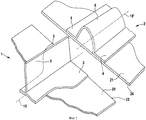
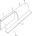
фиг.1 - схематический вид двух усиливающих элементов с разными профилями поперечного сечения вместе с элементами каркаса;figure 1 is a schematic view of two reinforcing elements with different profiles of the cross section together with the frame elements;
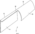
Фиг.2 - вариант осуществления соединительного элемента головной части соединительного устройства согласно изобретению;Figure 2 is an embodiment of a connecting element of the head of the connecting device according to the invention;
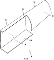
Фиг.3 - схематический перспективный вид первого варианта осуществления соединительного устройства согласно изобретению с соединительным элементом головной части согласно Фиг.2 для усиливающих элементов согласно Фиг.1;Figure 3 is a schematic perspective view of a first embodiment of a connecting device according to the invention with a connecting element of the head according to Figure 2 for reinforcing elements according to Figure 1;
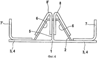
Фиг.4 - вид сбоку в продольном направлении соединительного устройства настоящего изобретения согласно Фиг.3 со вторым соединительным элементом основания, причем центральные линии усиливающих элементов выровнены;Figure 4 is a side view in the longitudinal direction of the connecting device of the present invention according to Figure 3 with the second connecting element of the base, and the center lines of the reinforcing elements are aligned;
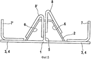
Фиг.5 - вид согласно Фиг.4, когда центральные линии усиливающих элементов смещены вбок;Figure 5 is a view according to Figure 4, when the center lines of the reinforcing elements are laterally offset;
Фиг.6 - еще один вариант осуществления соединительного элемента головной части соединительного устройства согласно изобретению;6 is another embodiment of a connecting element of the head of the connecting device according to the invention;
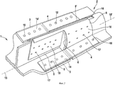
Фиг.7 - схематический перспективный вид второго варианта осуществления соединительного устройства согласно изобретению с соединительным элементов головной части согласно Фиг.6 для усиливающих элементов согласно Фиг.1;7 is a schematic perspective view of a second embodiment of a connecting device according to the invention with connecting elements of the head according to FIG. 6 for reinforcing elements according to FIG. 1;
Фиг.8 - еще один вариант осуществления соединительного элемента головной части соединительного устройства согласно изобретению; иFig. 8 is yet another embodiment of a connecting element of a head of a connecting device according to the invention; and
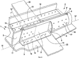
Фиг.9 - схематический перспективный вид третьего варианта осуществления соединительного устройства согласно изобретению с соединительным элементов головной части согласно Фиг.8 для усиливающих элементов согласно Фиг.1 с соединительным стыком двух элементов каркаса.Fig. 9 is a schematic perspective view of a third embodiment of a connecting device according to the invention with connecting elements of a head part according to Fig. 8 for reinforcing elements according to Fig. 1 with a connecting joint of two frame elements.
Одинаковые ссылочные номера на чертежах обозначают одинаковые или функционально идентичные компоненты, если не указано иное.The same reference numbers in the drawings indicate the same or functionally identical components, unless otherwise indicated.
На Фиг.1 представлен схематический вид двух усиливающих элементов 1, 2, имеющих разные профили поперечного сечения, с центральными осями 15, 15', которые проходят в продольном направлении упомянутых усиливающих элементов 1, 2. Усиливающие элементы 1, 2 здесь прикреплены к элементам обшивки 20, 21 для их усиления. Элементами 20, 21 являются, например, панели обшивки для самолета, и они выполнены из волокнистого композитного материала, хотя также можно использовать металл.Figure 1 presents a schematic view of two reinforcing
В данном случае два усиливающих элемента 1, 2 расположены на крае точки соединения элементов обшивки 20, 21. В этой точке соединения элементы обшивки 20, 21 имеют поперечные соединительные края 23, 24, на которых они примыкают друг к другу после их соединения. Это соединение описано ниже.In this case, two reinforcing
Первый усиливающий элемент 1 выполнен как Т-образный стрингер с основанием 3 и головной частью 5. В противоположность ему, второй усиливающий элемент 2 имеет полый профиль поперечного сечения с головной частью 6 и основанием 4 и в данной конфигурации также называется омега-образным стрингером. После соединения элементов обшивки 20, 21 усиливающие элементы 1, 2 также необходимо соединить для усиления и для передачи сил. На Фиг.1 показаны усиливающие элементы 1, 2 на крае элементов обшивки 20, 21. Однако также можно расположить эти два усиливающих элемента 1, 2 с разным профилем поперечного сечения с разными профилями поперечного сечения в любом другом месте на поверхности компонента обшивки или элемента обшивки 20, 21 и соединить их.The first reinforcing element 1 is designed as a T-shaped stringer with a
Для соединения друг с другом усиливающих элементов 1, 2 с разными профилями поперечного сечения основания 3, 4, а также головные части 5, 6 должны быть соединены положительно и не положительно, используя соединительное устройство. Это показано соединительным элементом головной части 8 на Фиг.2 в одном варианте осуществления соединительного устройства согласно изобретению. Фиг 2 будет описана вместе с Фиг.3, на которой показан схематический перспективный вид первого варианта осуществления соединительного устройства настоящего изобретения с соединительным элементом головной части 8 согласно Фиг.2 для усиливающих элементов 1, 2 согласно Фиг.1.To connect reinforcing
Соединительный элемент головной части 8 имеет плоскую соединительную поверхность 9, которая соответствует головной части 5 первого усиливающего элемента 1, Т-образного стрингера. Соединительная полка 13 выполнена неразъемно с продольным соединительным краем 11, расположенным выше на Фиг.2, соединительной поверхности 9, проходит по всему продольному соединительному краю 11, затем далее в его продольном направлении и соединена с продольным соединительным краем 12 соединительной профилированной поверхности 10. Форма соединительной профилированной поверхности 10 соответствует наружной поверхности второго усиливающего элемента 2, омега-образного стрингера. В данном примере соединительная полка 13 изогнута по продольным краям 11 и 12 на заранее определенную величину и на конкретный радиус в каждом случае, чтобы достигнуть конкретной жесткости соединительного элемента головной части 8. Соединительный элемент головной части 8 может быть изготовлен из металла и/или волокнистого композитного материала. При изготовлении из металла он может быть легко изготовлен как, например, штампованная изогнутая деталь.The connecting element of the
На Фиг.3 два усиливающих элемента 1, 2 применены для элемента обшивки (не показан) или также к его краям, как показано на Фиг.1. Центральные оси 15, 15' усиливающих элементов 1, 2 ориентированы по прямой и выровнены по отношению одна к другой. Соединительный элемент головной части 8 жестко установлен, например, с помощью заклепок, как верхнее крепление 17 с плоской соединительной поверхностью 9 на головную часть 5 Т-образного стрингера 1. На стороне омега-образного стрингера 2 соединительная профилированная поверхность 10 соединительного элемента головной части 8 прикреплена таким же образом к головной части 6 омега-образного стрингера 2. В данном примере на другой стороне головных частей 5 и 6 еще один зеркально перевернутый соединительный элемент головной части 8' прикреплен по такой же конструкции и таким же образом к головным частям 5 и 6 усиливающих элементов 1 и 2. Этот вариант осуществления соединительных элементов головных частей 8, 8', а именно то, что соединительная профилированная поверхность 10 начинается только приблизительно в центре соединительного элемента головной части 8, 8', дает возможность легко осматривать омега-образный стрингер 2 в точке соединения через полученный таким образом зазор. С другой стороны омега-образного стрингера 2 в данном варианте осуществления также можно, чтобы второй усиливающий элемент имел выемку 16 в его головной стороне по его продольному направлению.In Fig. 3, two reinforcing
Следовательно, с одной стороны также возможен простой осмотр и с другой стороны здесь может быть размещен изогнутый продольный соединительный край 12.Therefore, on the one hand, a simple inspection is also possible, and on the other hand, a curved longitudinal connecting
Соединительные элементы 7, 7' основания, из которых здесь показан только один, предусмотрены для соединения оснований 3 и 4 усиливающих элементов 1, 2. Соединительный элемент 7, 7' основания выполнен в данном примере как L-образная профилированная деталь и как и соединительный элемент головной части 8, 8' может быть изготовлен из металла и/или волокнистого композитного материала. Как профилированная деталь он может быть удобно разрезан на отрезки, просто как прутковый материал. На своей нижней стороне он лежит на соединяемых основаниях 3, 4 усиливающих элементов 1, 2 и жестко соединен с ними с использованием креплений 18 оснований, например заклепками. Чтобы получить большую поверхность передачи сил, основание 3 Т-образного стрингера 1 в данном примере расширено и адаптировано к основанию омега-образного стрингера 2. Однако расширение в этой точке соединения может быть предварительно адаптировано соответствующим образом, исходя из конкретной конфигурации.The
На Фиг.3 усиливающие элементы 1, 2 ориентированы по выравниваемым центральным осям 15, 15'. При этом Фиг.4 представляет собой вид с Фиг.3 в направлении центральных осей 15, 15'. На Фиг.4 также показан второй соединительный элемент 7 основания, который не показан на Фиг.3. Это расположение симметрично плоскости, в которой проходят выравниваемые центральные оси 15, 15'. Также понимается, что вместо двойных соединительных элементов 7, 7' и 8, 8' в каждом случае можно использовать только один из них (например, 7 и 8') или их можно использовать в другом сочетании.In Fig. 3, the reinforcing
Если существует боковое смещение центральных осей 15, 15', как показано на Фиг.5 в продольном направлении центральных осей 15, 15' с Фиг.3 по сравнению с Фиг.4, это смещение можно выгодно компенсировать без промежуточных слоев, также называемых регулировочными прокладками, в первом варианте осуществления соединительного элемента 8, 8' головной части соединительного устройства согласно изобретению, в конкретном диапазоне допусков так, что два соединительных элемента головных частей 8, 8' будут перемещены вверх или вниз, в зависимости от направления смещения, на косой наружной поверхности омега-образного стрингера 2. Таким образом обеспечивается соединение между головными частями 5 и 6 без использования прокладок.If there is a lateral displacement of the
Еще один вариант осуществления соединительного элемента головной части 8 соединительного устройства согласно изобретению показан на Фиг.6, которая будет описана вместе с Фиг.7. На Фиг.7 показан схематический перспективный вид второго варианта осуществления соединительного устройства согласно изобретению с соединительным элементом 8 головной части согласно Фиг.6 для усиливающих элементов согласно Фиг.1.Another embodiment of the connecting element of the
В этом варианте осуществления соединительный элемент основания 7 в форме соединительной поверхности 14 основания выполнен как одно целое или неразъемно с соединительным элементом 8 головной части. В данном случае соединительную поверхность 14 основания крепят к продольному краю соединительной профилированной поверхности 10, который расположен напротив продольного соединительного края 12. В остальном соединительный элемент головной части 8 выполнен так же, как и первый вариант осуществления согласно Фиг.2. Конечно, соединительная поверхность 14 основания так же может быть выполнена как L-образная профилированная деталь или ей подобная.In this embodiment, the connecting element of the
Зеркально перевернутый цельный соединительный элемент головной части 8' легко вообразить, и он показан на Фиг.7. На Фиг.7 показана конструкция, подобная конструкции на Фиг.3, которая уже была описана. Разница с Фиг.3 заключается в том, что соединительные элементы 8, 8' головных частей выполнены неразъемно с соединительными элементами 7, 7' основания, здесь как соединительные поверхности 14, 14' основания. Соединительные поверхности 14, 14' жестко соединены с основаниями 3, 4 усиливающих элементов 1, 2 в креплениях 18 оснований, например, заклепками.The mirrored inverted integral connecting element of the head part 8 'is easy to imagine, and it is shown in Fig.7. FIG. 7 shows a structure similar to that of FIG. 3, which has already been described. The difference with Figure 3 lies in the fact that the connecting
Цельный соединительный элемент 8, 8' головной части имеет преимущество в небольшом количестве деталей по сравнению с первым вариантом осуществления. Если существует боковое смещение центральных осей 15, 15' усиливающих элементов 1, 2, для компенсации необходимо использовать прокладки как промежуточные слои.The integral
В еще одном варианте осуществления соединительного элемента 8 головной части, показанном на Фиг.8, также можно закрепить соединительный элемент 7 основания неразъемно с плоской соединительной поверхностью 9 соединительного элемента 8 головной части. Описание уже дано в связи с Фиг.6 и 7.In yet another embodiment of the
В заключение, на Фиг.9 показан третий вариант осуществления соединительного устройства согласно изобретению с соединительными элементами головных частей 8, 8' варианта осуществления согласно Фиг.8 в удлинении соединительных поверхностей 9, 9' и таким образом выполненных неразъемно соединительных поверхностей 14, 14' основания в точке соединения элементов обшивки 20, 21 согласно Фиг.1. Кроме того, предусмотрены соединительные элементы 7, 7' основания для соединения оснований 3 и 4, и соединительный элемент 7 основания, который был бы на переднем плане, не показан.In conclusion, FIG. 9 shows a third embodiment of a connecting device according to the invention with connecting elements of the
Эта точка соединения элементов обшивки 20, 21 имеет поперечную стыковую накладку 22, которая более подробно не описана. К обеим сторонам этой поперечной стыковой накладки 22 прилегают усиливающие элементы 1, 2 с зазором между ними, который перекрывается расширенными соединительными поверхностями 9'. Как сказано выше, соединительные элементы 8, 8' головных частей соединены с соответствующими головными частями 5, 6 усиливающих элементов 1, 2. Соединительные поверхности 14, 14' основания и соединительные элементы 7, 7' основания жестко соединены на креплениях 18 основания с основаниями 3, 4 усиливающих элементов 1, 2, как сказано выше. Кроме того, соединительные элементы 7, 7' основания и соединительные поверхности 14, 14' основания жестко соединены, например, заклепками, их частями, расположенными выше поперечной стыковой накладки 22 с этой поперечной стыковой накладкой 22 на креплениях 19, чтобы таким образом достигнуть достаточно высокой жесткости и прочности соединительного устройства.This connection point of the
Хотя настоящее изобретение описано на основе предпочтительных вариантов осуществления, оно ими не ограничено, и может быть объединено и модифицировано многими различными способами.Although the present invention has been described based on preferred embodiments, it is not limited thereto, and can be combined and modified in many different ways.
Например, соединительная поверхность 9 соединительного элемента 8, 8' головной части может выходить за границы соединительной профилированной поверхности 10. Соединительная профилированная поверхность 10 также может проходить дальше впереди соединительной поверхности 9, в результате чего можно получить повышенную прочность и жесткость.For example, the connecting
Усиливающие элементы 1, 2, подсоединяемые с использованием соединительного устройства согласно изобретению, могут быть расположены в любом месте на элементе обшивки 20, 21, таким образом также в точке соединения элементов обшивки 20, 21 с поперечной стыковой накладкой 22 или без нее.Reinforcing
Также возможны и другие формы профилированной детали усиливающих элементов 1, 2.Other shapes of the profiled part of the reinforcing
В соединительном устройстве для соединения двух усиливающих элементов 1, 2 самолета или космического летательного аппарата, усиливающие элементы 1, 2 с разными профилями поперечного сечения, имеющие в каждом случае по меньшей мере одно основание 3, 4 и по меньшей мере одну головную часть 5, 6, существует по меньшей мере один соединительный элемент 7, 7' основания, который на одной стороне может быть приспособлен к геометрической форме основания 3 первого усиливающего элемента 1, и на противоположной стороне может быть приспособлен к геометрической форме основания 4 второго усиливающего элемента 2, и может быть жестко соединен с ними в каждом случае; и по меньшей мере один соединительный элемент 8, 8' головной части, который на одной стороне может быть приспособлен к геометрической форме головной части 5 первого усиливающего элемента 1, и на противоположной стороне может быть приспособлен к геометрической форме головной части 6 второго усиливающего элемента 2, и может быть жестко соединен с ними в каждом случае. Соединительное устройство имеет компонент обшивки по меньшей мере с двумя усиливающими элементами 1, 2, имеющими разные профили поперечного сечения.In a connecting device for connecting two reinforcing
Перечень ссылочных номеровList of Reference Numbers
1, 2 Усиливающий элемент (Т-образный стрингер, омега-образный стрингер)1, 2 Reinforcing element (T-shaped stringer, omega-shaped stringer)
3, 4 Основание3, 4 Base
5, 6 Головная часть5, 6 Head part
7, 7' Соединительный элемент основания7, 7 'Base connector
8, 8' Соединительный элемент головной части8, 8 'Connecting element of the head
9 Соединительная поверхность9 Connecting surface
10 Соединительная профилированная поверхность10 Connecting profiled surface
11 Соединительная поверхность продольного соединительного края11 The connecting surface of the longitudinal connecting edge
13 Соединительная профилированная поверхность продольного соединительного края13 Connecting profiled surface of the longitudinal connecting edge
13 Соединительная полка13 Connecting shelf
14 Соединительная поверхность основания14 Connecting surface of the base
15, 15' Центральная ось15, 15 'Central axis
16 Выемка16 notch
17 Крепление головной части17 Mounting the head
18 Крепление основания18 Base mounting
19 Крепление поперечной стыковой накладки19 Fastening the transverse butt plate
20, 21 Элемент обшивки20, 21 Covering element
22 Поперечная стыковая накладка22 transverse butt plate
23, 24 Край поперечной стыковой накладки23, 24 Edge of the transverse butt plate
Claims (17)
по меньшей мере один соединительный элемент (7, 7') основания, который на одной стороне может быть приспособлен к геометрической форме основания (3) первого усиливающего элемента (1) и на противоположной стороне может быть приспособлен к геометрической форме основания (4) второго усиливающего элемента (2) и может быть жестко соединен с ними в каждом случае; и
по меньшей мере один соединительный элемент (8, 8') головной части, который на одной стороне может быть приспособлен к геометрической форме головной части (5) первого усиливающего элемента (1) и на противоположной стороне может быть приспособлен к геометрической форме головной части (6) второго усиливающего элемента (2) и может быть жестко соединен с ними в каждом случае.1. A connecting device for connecting two reinforcing elements (1, 2) of an airplane or a spacecraft, and the reinforcing elements (1, 2) have different cross-sectional profiles in each case with at least one base (3, 4) and at least with at least one head part (5, 6), and the connecting device contains:
at least one base connecting element (7, 7 ′), which on one side can be adapted to the geometric shape of the base (3) of the first reinforcing element (1) and on the opposite side can be adapted to the geometric shape of the base (4) of the second reinforcing element (2) and can be rigidly connected to them in each case; and
at least one connecting element (8, 8 ') of the head part, which on one side can be adapted to the geometric shape of the head part (5) of the first reinforcing element (1) and on the opposite side can be adapted to the geometric shape of the head part (6 ) of the second reinforcing element (2) and can be rigidly connected to them in each case.
Applications Claiming Priority (5)
| Application Number | Priority Date | Filing Date | Title |
|---|---|---|---|
| US6301208P | 2008-01-30 | 2008-01-30 | |
| DE102008006834A DE102008006834A1 (en) | 2008-01-30 | 2008-01-30 | Connecting arrangement for connecting two stiffening elements of different cross-sectional profile for an aircraft or spacecraft, and a shell component |
| US61/063,012 | 2008-01-30 | ||
| DE102008006834.9 | 2008-01-30 | ||
| PCT/EP2008/067214 WO2009095133A2 (en) | 2008-01-30 | 2008-12-10 | Connecting arrangement for joining two stiffening elements having different cross-sectional profiles for an aircraft or spacecraft, and shell component |
Publications (2)
| Publication Number | Publication Date |
|---|---|
| RU2010128137A RU2010128137A (en) | 2012-01-20 |
| RU2482017C2 true RU2482017C2 (en) | 2013-05-20 |
Family
ID=40913325
Family Applications (1)
| Application Number | Title | Priority Date | Filing Date |
|---|---|---|---|
| RU2010128137/11A RU2482017C2 (en) | 2008-01-30 | 2008-12-10 | Connector for jointing two reinforcing elements with different profiles of cross-section for aircraft or spacecraft and skin component |
Country Status (10)
| Country | Link |
|---|---|
| US (1) | US8528865B2 (en) |
| EP (1) | EP2238021B1 (en) |
| JP (1) | JP2011510859A (en) |
| CN (1) | CN101932506B (en) |
| AT (1) | ATE505398T1 (en) |
| BR (1) | BRPI0822041A2 (en) |
| CA (1) | CA2712062A1 (en) |
| DE (2) | DE102008006834A1 (en) |
| RU (1) | RU2482017C2 (en) |
| WO (1) | WO2009095133A2 (en) |
Families Citing this family (12)
| Publication number | Priority date | Publication date | Assignee | Title |
|---|---|---|---|---|
| DE102008012252B4 (en) * | 2008-03-03 | 2014-07-31 | Airbus Operations Gmbh | Composite as well as aircraft or spacecraft with such a composite |
| ES2384250B1 (en) * | 2009-09-30 | 2013-05-16 | Airbus Operations, S.L. | UNION OF AIRCRAFT STRUCTURAL ELEMENTS. |
| DE102010042970A1 (en) * | 2010-05-12 | 2011-11-17 | Airbus Operations Gmbh | Structural component with improved conductivity and mechanical strength and method for its production |
| ES2398985B1 (en) * | 2011-03-14 | 2014-02-14 | Airbus Operations S.L. | LOAD TRANSFER DEVICES IN THE TERMINATION OF A LARGUERILLO. |
| FR2984844B1 (en) * | 2011-12-21 | 2014-02-28 | Airbus Operations Sas | ANTI-SPEED AIRCRAFT FUSELAGE STRUCTURE ELEMENT |
| FR2993856B1 (en) * | 2012-07-30 | 2015-09-18 | Airbus Operations Sas | AIRCRAFT FUSELAGE STRUCTURE ELEMENT HAVING AN EVOLVING SECTION |
| FR3007735B1 (en) * | 2013-06-28 | 2015-08-07 | Airbus Operations Sas | CONNECTING AN AIRCRAFT FUSELAGE MEMBER AND A FRAME BY A SPACER AND A THRUST |
| US9656319B2 (en) * | 2013-11-13 | 2017-05-23 | The Boeing Company | Positioning system for electromagnetic riveting |
| EP2907743A1 (en) * | 2014-02-13 | 2015-08-19 | Airbus Operations GmbH | Stiffening element, method for coupling the same, and shell component for an aircraft or spacecraft |
| US9724848B2 (en) * | 2014-07-03 | 2017-08-08 | The Boeing Company | Collapsible, coiled mandrel |
| US11198497B2 (en) | 2019-06-19 | 2021-12-14 | The Boeing Company | Splice fittings that are affixed to stringers via web-installed fasteners |
| CN113290117B (en) * | 2021-05-21 | 2022-09-09 | 青岛中天鹏锻压制造有限公司 | Plastic forming method and mould for traction beam web of rail transit vehicle |
Citations (3)
| Publication number | Priority date | Publication date | Assignee | Title |
|---|---|---|---|---|
| SU967017A1 (en) * | 1980-07-14 | 1991-10-30 | Предприятие П/Я В-2739 | Stringer of aircraft panel |
| RU2179136C2 (en) * | 1999-06-21 | 2002-02-10 | Комсомольское-на-Амуре авиационное производственное объединение | Method of assembly of flying vehicle units |
| US20060060705A1 (en) * | 2004-09-23 | 2006-03-23 | Stulc Jeffrey F | Splice joints for composite aircraft fuselages and other structures |
Family Cites Families (25)
| Publication number | Priority date | Publication date | Assignee | Title |
|---|---|---|---|---|
| US1854330A (en) * | 1928-12-20 | 1932-04-19 | Nieuportastra Sa | Metallic construction of aircraft |
| US2383634A (en) * | 1943-02-20 | 1945-08-28 | Budd Edward G Mfg Co | Main frame structure for airfoils or the like |
| US2382358A (en) * | 1944-02-03 | 1945-08-14 | Budd Edward G Mfg Co | Stressed skin airfoil joint |
| US3004645A (en) * | 1959-08-27 | 1961-10-17 | Jr George E Moul | Aerodynamic surface attaching structure |
| US3827661A (en) * | 1972-07-26 | 1974-08-06 | Ryson Aviat Corp | Aircraft wing structure and method of assembly |
| US4256790A (en) * | 1978-01-19 | 1981-03-17 | Rockwell International Corporation | Reinforced composite structure and method of fabrication thereof |
| US4813202A (en) * | 1987-05-22 | 1989-03-21 | Grumman Aerospace Corporation | Structural members connected by interdigitating portions |
| JPH05286493A (en) * | 1992-04-08 | 1993-11-02 | Honda Motor Co Ltd | Fuselage structure of aircraft |
| US5518208A (en) * | 1993-12-28 | 1996-05-21 | The Boeing Company | Optimum aircraft body frame to body skin shear tie installation pattern for body skin/stringer circumferential splices |
| US6375120B1 (en) * | 1997-07-14 | 2002-04-23 | Jason M. Wolnek | Method and apparatus for building a metal/composite hybrid airplane component |
| US6105902A (en) * | 1997-07-15 | 2000-08-22 | Mcdonnell Douglas Corporation | Aircraft fuselage and method of forming same |
| DE19844035C1 (en) * | 1998-09-25 | 1999-11-25 | Daimler Chrysler Aerospace | Shell component for an aircraft, and method for its production |
| US7681835B2 (en) * | 1999-11-18 | 2010-03-23 | Rocky Mountain Composites, Inc. | Single piece co-cure composite wing |
| DE10007995C2 (en) * | 2000-02-22 | 2002-03-07 | Airbus Gmbh | Structural component, in particular for an aircraft and method for producing a structural component |
| DE10031510A1 (en) * | 2000-06-28 | 2002-01-17 | Airbus Gmbh | Structural component for an aircraft |
| US7205066B1 (en) * | 2002-05-23 | 2007-04-17 | Rohr, Inc. | Structural element with rib-receiving member |
| US8585313B2 (en) * | 2005-01-27 | 2013-11-19 | Edsal Manufacturing Co., Inc. | Post coupler |
| US7530531B2 (en) * | 2004-10-04 | 2009-05-12 | The Boeing Company | Apparatus and methods for installing an aircraft window panel |
| US7555873B2 (en) * | 2004-11-30 | 2009-07-07 | The Boeing Company | Self-locating feature for a pi-joint assembly |
| US7410120B2 (en) * | 2005-01-21 | 2008-08-12 | The Boeing Company | Control surface assemblies with torque tube base |
| DE102006008455A1 (en) | 2006-02-18 | 2007-10-18 | Emil Bucher Gmbh & Co.Kg Modell-Und Maschinenbau | Method for applying adhesive to stringer used in making airfoils comprises applying tape with adhesive, support and removable protective layers to flanges, protective layer being removed and tape cut to fit before it is pressed on |
| IL184216A0 (en) | 2007-06-25 | 2008-01-06 | Rafael Advanced Defense Sys | Two-stage airbag inflation system with pyrotechnic delay |
| DE102007029500B4 (en) * | 2007-06-25 | 2013-02-14 | Airbus Operations Gmbh | Method for coupling stiffening profile elements and structural component |
| DE102007033868B4 (en) * | 2007-07-20 | 2013-01-31 | Airbus Operations Gmbh | Profile with at least one hollow profile cross-section |
| DE102008002117B4 (en) | 2008-05-30 | 2013-10-31 | Airbus Operations Gmbh | Composite and structure |
-
2008
- 2008-01-30 DE DE102008006834A patent/DE102008006834A1/en not_active Withdrawn
- 2008-12-10 AT AT08871637T patent/ATE505398T1/en active
- 2008-12-10 BR BRPI0822041A patent/BRPI0822041A2/en not_active IP Right Cessation
- 2008-12-10 CA CA2712062A patent/CA2712062A1/en not_active Abandoned
- 2008-12-10 CN CN200880125939.3A patent/CN101932506B/en not_active Expired - Fee Related
- 2008-12-10 WO PCT/EP2008/067214 patent/WO2009095133A2/en active Application Filing
- 2008-12-10 JP JP2010544603A patent/JP2011510859A/en active Pending
- 2008-12-10 EP EP08871637A patent/EP2238021B1/en not_active Not-in-force
- 2008-12-10 DE DE502008003231T patent/DE502008003231D1/en active Active
- 2008-12-10 RU RU2010128137/11A patent/RU2482017C2/en not_active IP Right Cessation
-
2010
- 2010-07-19 US US12/838,950 patent/US8528865B2/en active Active
Patent Citations (3)
| Publication number | Priority date | Publication date | Assignee | Title |
|---|---|---|---|---|
| SU967017A1 (en) * | 1980-07-14 | 1991-10-30 | Предприятие П/Я В-2739 | Stringer of aircraft panel |
| RU2179136C2 (en) * | 1999-06-21 | 2002-02-10 | Комсомольское-на-Амуре авиационное производственное объединение | Method of assembly of flying vehicle units |
| US20060060705A1 (en) * | 2004-09-23 | 2006-03-23 | Stulc Jeffrey F | Splice joints for composite aircraft fuselages and other structures |
Also Published As
| Publication number | Publication date |
|---|---|
| CA2712062A1 (en) | 2009-08-06 |
| WO2009095133A2 (en) | 2009-08-06 |
| US20110011980A1 (en) | 2011-01-20 |
| ATE505398T1 (en) | 2011-04-15 |
| EP2238021B1 (en) | 2011-04-13 |
| JP2011510859A (en) | 2011-04-07 |
| EP2238021A2 (en) | 2010-10-13 |
| WO2009095133A3 (en) | 2009-10-22 |
| DE502008003231D1 (en) | 2011-05-26 |
| DE102008006834A1 (en) | 2009-10-15 |
| CN101932506A (en) | 2010-12-29 |
| BRPI0822041A2 (en) | 2019-09-24 |
| CN101932506B (en) | 2014-06-11 |
| US8528865B2 (en) | 2013-09-10 |
| RU2010128137A (en) | 2012-01-20 |
Similar Documents
| Publication | Publication Date | Title |
|---|---|---|
| RU2482017C2 (en) | Connector for jointing two reinforcing elements with different profiles of cross-section for aircraft or spacecraft and skin component | |
| US8371529B2 (en) | Interconnection and aircraft or spacecraft having such an interconnection | |
| EP2822852B1 (en) | Bonded splice joint | |
| RU2658211C2 (en) | Circumferential butt joint for skin structures | |
| US7857258B2 (en) | Assembly of panels of an airplane fuselage | |
| US9963218B2 (en) | Lightweight structural panel | |
| US8302909B2 (en) | Splicing of omega-shaped stiffeners at a circumferential joint in an aircraft fuselage | |
| US7837148B2 (en) | Composite wing-body joint | |
| JP4604118B2 (en) | Asymmetric carbon metal mixed seam joining apparatus and method | |
| US9771140B2 (en) | Aircraft structure with integrated reinforcing elements | |
| JP2010531259A (en) | Reinforced profile connecting method and structural parts | |
| US8899522B2 (en) | Aircraft fuselage with high strength frames | |
| WO2009112694A3 (en) | Curved structural part made of composite material and method of manufacturing such a part | |
| JP2013540608A5 (en) | ||
| JP2013540608A (en) | Machinable composite materials | |
| EP3652067B1 (en) | Fitting for a stiffened panel | |
| CN113291454A (en) | Fuselage structure splice |
Legal Events
| Date | Code | Title | Description |
|---|---|---|---|
| MM4A | The patent is invalid due to non-payment of fees |
Effective date: 20171211 |