EP2237998B1 - Getriebegehäuse einer wischeranlage mit einem steckpunkt als befestigungspunkt - Google Patents
Getriebegehäuse einer wischeranlage mit einem steckpunkt als befestigungspunkt Download PDFInfo
- Publication number
- EP2237998B1 EP2237998B1 EP08871483.7A EP08871483A EP2237998B1 EP 2237998 B1 EP2237998 B1 EP 2237998B1 EP 08871483 A EP08871483 A EP 08871483A EP 2237998 B1 EP2237998 B1 EP 2237998B1
- Authority
- EP
- European Patent Office
- Prior art keywords
- point
- plug
- gear housing
- receptacle
- connecting portion
- Prior art date
- Legal status (The legal status is an assumption and is not a legal conclusion. Google has not performed a legal analysis and makes no representation as to the accuracy of the status listed.)
- Not-in-force
Links
- 230000005540 biological transmission Effects 0.000 description 37
- 230000013011 mating Effects 0.000 description 13
- 229910052751 metal Inorganic materials 0.000 description 8
- 239000002184 metal Substances 0.000 description 8
- 238000001816 cooling Methods 0.000 description 4
- 239000000463 material Substances 0.000 description 4
- 238000010079 rubber tapping Methods 0.000 description 4
- 229910052782 aluminium Inorganic materials 0.000 description 3
- XAGFODPZIPBFFR-UHFFFAOYSA-N aluminium Chemical compound [Al] XAGFODPZIPBFFR-UHFFFAOYSA-N 0.000 description 3
- 229910000838 Al alloy Inorganic materials 0.000 description 2
- 238000002347 injection Methods 0.000 description 2
- 239000007924 injection Substances 0.000 description 2
- 230000037431 insertion Effects 0.000 description 2
- 238000003780 insertion Methods 0.000 description 2
- 239000000969 carrier Substances 0.000 description 1
- 238000010276 construction Methods 0.000 description 1
- 238000004049 embossing Methods 0.000 description 1
- 239000003292 glue Substances 0.000 description 1
- 238000004519 manufacturing process Methods 0.000 description 1
- 229910001092 metal group alloy Inorganic materials 0.000 description 1
- 238000004806 packaging method and process Methods 0.000 description 1
- 230000003014 reinforcing effect Effects 0.000 description 1
Images





Classifications
-
- B—PERFORMING OPERATIONS; TRANSPORTING
- B60—VEHICLES IN GENERAL
- B60S—SERVICING, CLEANING, REPAIRING, SUPPORTING, LIFTING, OR MANOEUVRING OF VEHICLES, NOT OTHERWISE PROVIDED FOR
- B60S1/00—Cleaning of vehicles
- B60S1/02—Cleaning windscreens, windows or optical devices
- B60S1/04—Wipers or the like, e.g. scrapers
- B60S1/043—Attachment of the wiper assembly to the vehicle
- B60S1/0433—Attachement of a wiper modular assembly to the vehicle
-
- B—PERFORMING OPERATIONS; TRANSPORTING
- B60—VEHICLES IN GENERAL
- B60S—SERVICING, CLEANING, REPAIRING, SUPPORTING, LIFTING, OR MANOEUVRING OF VEHICLES, NOT OTHERWISE PROVIDED FOR
- B60S1/00—Cleaning of vehicles
- B60S1/02—Cleaning windscreens, windows or optical devices
- B60S1/04—Wipers or the like, e.g. scrapers
- B60S1/043—Attachment of the wiper assembly to the vehicle
- B60S1/0441—Attachment of the wiper assembly to the vehicle characterised by the attachment means
- B60S1/0447—Attachment of the wiper assembly to the vehicle characterised by the attachment means non-screw fixation, (e.g. snap-in, bayonnet-type..)
Definitions
- the invention relates to a transmission housing of a wiper system with a plug-in point as an attachment point for attaching the wiper system to a vehicle.
- the publication WO 2005/025951 A1 shows a generic windshield wiper device for a motor vehicle.
- the device comprises a transmission housing, which is fastened by means of decoupling elements on the vehicle body.
- the decoupling elements threaded screws for the purpose of screwing the decoupling elements on the vehicle body.
- the publication FR 2887830 A shows a windshield wiper device comprising a housing comprising three attachment arms, which are fastened to a vehicle body.
- the publication JP 60042121 A shows a transmission housing a wiper system, wherein the housing is secured by means of stepped angled components to a vehicle body.
- the publication WO 2005/097565 A1 shows a windshield wiper device with at least one attachable to a vehicle body drive element and at least two axially rigidly arranged fastening elements, which are able to engage in receiving openings on the vehicle body.
- the patent US 2,270,589 shows a transmission housing a wiper system, which is screwed to a double-walled reinforcing element of a body.
- the publication FR 2859403 shows a tool for attaching a wiper system to a vehicle body.
- a transmission housing for a wiper system, wherein the transmission housing is provided with at least one plug-in point, for attachment to a vehicle.
- the plug-in point is fastened as a separate or separate part to the transmission housing.
- a mating point for example, easily be attached later at different positions of the gear housing or omitted entirely, depending on the customer requirement.
- different injection tools for the gearbox housing are not necessary, as in the prior art, for example, if there are variations in the plug-in point.
- the plug-in point has a connecting portion with which the plug-in point can be connected to the gear housing or attached thereto.
- the mating point has a fixing portion, for example, a pin portion to be attached to a vehicle or to be attached thereto.
- the connecting portion may be formed, for example, as a threaded screw portion, the screw portion being e.g. can form a self-tapping screw portion.
- the gear housing is additionally provided with at least one receptacle to introduce the connecting portion of the plug-in point therein and, optionally, to lock, jam and / or glue therein, for example.
- a plug-in foot can also be fixed in places where it could not be easily screwed before.
- the recording consists for example of two L-shaped guides.
- the receptacle can also be U-shaped to provide two guides, in which a correspondingly shaped connecting portion can be inserted.
- a connecting portion can be securely held in the receptacle without slipping unintentionally.
- a plug-in point in such a receptacle is easy to assemble.
- the connecting portion is formed as a flattened portion.
- the flattened portion has at least one or two openings into which a rivet, a bolt or a screw can be inserted to the connecting portion to attach to the gear housing by means of riveting, bolting or bolting.
- self-tapping screws can be used as screws.
- the connecting portion is formed with a hook element.
- the gear housing is in this case formed with a corresponding recess or a shaft into which the hook element can be hooked. This has the advantage that the plug-in point can be mounted very easily.
- the connecting portion and the attachment portion are formed as a pin member or cylindrical.
- a corresponding receptacle is provided on the transmission housing, in which the connecting portion can engage.
- the connecting portion has two forwardly bent ends, so that the connecting portion forms a U-shape.
- the two ends of the connecting portion are inserted into corresponding guides of a locking receptacle and locked for example therein.
- the locking receptacle with the plug point is in turn snapped onto the transmission housing.
- the latching receptacle has a corresponding latching hook which can engage on a housing wall of the gearbox housing. This has the advantage that a plug-in point can be very easily attached to different positions on the gear housing, depending on the customer.
- Fig. 1 is a front wiper system 10 for a vehicle shown according to the prior art.
- the front wiper system 10 in this case has three attachment points 12, with which the front wiper system 10 is mounted in the respective vehicle.
- the third of the attachment points 12, as in Fig. 1 is shown, it is often designed as a plug-in point 14 to be plugged into a corresponding location of the vehicle and so to attach the front wiper system 10 thereto.
- the plug point 14 is according to the prior art, as in Fig. 1 is shown integrated in a circuit board 16 of the front wiper system 10.
- the plug point 14 is integrated on the engine.
- the plug point 14 is in this case integrally formed on the motor, as in the cutout in Fig. 2 is shown.
- Such a construction in which the mating point 14 is injected in the transmission housing 18, as in Fig. 2 shown has the following disadvantages.
- a basic engine concept with such an injected mating point 14 is not sustainable if the base engine is to be used for different customers in which the positions for the mating point 14 vary or where such mating point 14 is not desired or not needed.
- Different positions for the plug point 14 or the provision of no plug-in point 14 further leads to the fact that different injection tools are necessary to a transmission housing 18th of the motor with or without the desired mating point 14.
- This also results in the need to adapt workpiece carriers and production lines to the various positions of the plug-in points 14, depending on the customer requirements.
- an increased packaging costs and space is needed, so that the total cost of a wiper system increase.
- the mating point 14 is therefore not formed integrally with the gear housing 18, or molded onto this but attached to this as a separate part.
- the plug point 14 is subsequently attached to the respective gear housing 18 of the motor of the wiper system. This can be done in a variety of ways, for example by means of screws, embossing or caulking, jamming and / or latching, etc., to name just a few examples.
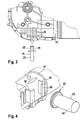
- Fig. 3 is a not belonging to the invention embodiment of the attachment of a plug-in point 14 to a transmission housing 18 of an engine of a front wiper system shown.
- the invention is not limited to front wiper systems, but can be used for all types of wiper systems, such as rear wiper systems, etc. This applies to all embodiments of the invention and in particular for the embodiments described below.
- the male point 14 has a mounting portion 20, for example in the form of a pin element with which it is attached to a vehicle. Furthermore, the plug point 14 has a connecting portion 22, with which it is connected to the motor or the gear housing 18 and fixed thereto.
- the connecting portion 22 has a thread 24, with which the plug point 14, comparable, for example, a tapping screw, drilled or screwed through a wall 26 of the gear housing 18. In this way, the plug point 14 be reliably attached to the transmission housing 18 or fixed thereto.
- the bore or the thread 24 for the connecting portion 22 can be prefabricated on the gear housing 18 or the connecting portion 22 can be drilled with its thread 24 in a thin-walled portion of the gear housing 18 directly. In the present case, as in Fig.
- the plug point 14 is drilled through a wall 26 of the gear housing, which is, for example, thin-walled, for example, a cooling rib.
- Such cooling fins serve to be cooled by the surrounding air.
- the plug point 14 can also be fastened to any other point of the transmission housing 18.
- the attachment to a cooling rib, as in Fig. 3 is shown is merely exemplary.
- the plug-in point 14 consists for example of a pin element as a mounting portion 20 and an example disc-shaped round or oval portion or a circuit board as a connecting portion 22.
- the connecting portion 22 and / or the attachment portion 20 may be made here, for example, as a sheet metal part.
- a receptacle 28 is provided on the transmission housing 18, for example with a guide 30 on each side, for guiding the connection section 22 or the circuit board.
- the guides 30 are formed in each case from an L-contour into which the plug-in point 14 with its connecting section 22 is inserted and latched therein.
- the board or the sheet metal part can in this case be designed such that it can dig in, for example, in the receptacle 28.
- the recording 28 can thereby For example, made of metal, such as aluminum or an aluminum alloy, etc. or other suitable material.
- a plug-in point 14 is provided, which has a pin element as a fastening portion 20 and an example disk-shaped, square or rectangular section or a board as a connecting portion 22.
- a U-shaped receptacle 28 in which the connecting portion 22 of the plug-in point is inserted.
- the receptacle 28 may be made of a metal, for example aluminum or an aluminum alloy or another material.
- the sides 32 of the U-shaped receptacle 28 are bent inwardly after the insertion point 14 has been introduced to fix the plug point 14 and its connecting portion 22 in the receptacle 28.
- the U-shaped contour for example made of metal, is cold-formed around the connecting portion 22 (for example, a sheet metal part).
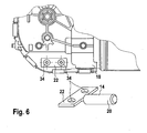
- the plug-in point 14 has as a connecting portion 22, for example, a pin portion and as a mounting portion 20, for example, a flattened portion with at least one or two passages or holes 34.
- the connecting portion 22 for example, riveted to this (rolled) or screwed , for example via self-tapping screws.
- the holes for the screws can also be predrilled and threaded.
- the connection section becomes 22 of the plug point 14, for example, riveted to an aluminum cylinder of the gear housing 18 (rolled).
- the transmission housing 18 is provided with a receptacle 28 in the form of a depression or a shaft.
- the plug point 14 has in this case as a fastening portion 20 on a pin member.
- the connecting portion 22 is formed in the form of a hook portion 36 which can hook or dig into the receptacle 28 or the shaft.
- the receptacle 28 or the shaft may be provided with an undercut for hooking.
- the plug-in point 14 is clipped to attach to the transmission housing 18 to a corresponding receptacle 28.
- the attachment points for the plug point 14 and the receptacle 28 are located, for example, only on the transmission housing 18.
- the gear cover (GD) is not touched in this case, for example.
- the mating point 14 according to the sixth embodiment, as a connecting portion 22 and mounting portion 20 has a continuous pin member, for example, with a circular or oval or square diameter.
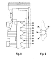
- the plug point 14 is in Fig. 7 shown here before attachment by clipping into the receptacle 28 on the transmission housing 18.
- Fig. 8 shows the plug point 14 then in the installed state, wherein the gear housing 18 is shown here in a side view.
- Fig. 9 the receptacle 28 of the gear housing 18 and the plug-in point 14 clipped therein is shown in a plan view.
- the gear housing 18 in this case has a latching receptacle 42 with a receptacle with 28 two guides 30, in which the plug-in point 14 is inserted with its connecting portion 22 and clipped.
- the plug point 14 has in this case as a fastening portion 20, a pin member and a connecting portion 22 a flattened portion, the side ends 40 are engaged in the two guides 30 of the receptacle 28.
- the two side ends 40 of the flattened portion may be bent in a U-shape to one side, as in Fig. 10 and the enlarged section in Fig. 11 is shown.
- the latching receptacle 42 with the plug point 14 is in turn latched to the transmission housing 18 and a wall of the transmission housing.
- the locking receptacle 42 has a corresponding latching hook 44, which can engage on a housing wall of the transmission housing 18.
- the attachment points of the connecting portion 22 of the plug point 14 are also, for example, only on the transmission housing 18.
- the gear cover (GD) is not touched, for example.
- the side ends 40 of the flattened portion of the connecting portion 22 may be formed, for example, thickened to lock into correspondingly shaped guides (not shown).
- the plug-in points 14 described in the embodiments with their connecting portion 22 and mounting portion 20 may be made of a material or a combination of materials.
- the connecting portion 22 and / or the attachment portion 20 may be made of metal or a metal alloy and / or plastic or, for example, be formed as a sheet metal part.
Landscapes
- Engineering & Computer Science (AREA)
- Mechanical Engineering (AREA)
- General Details Of Gearings (AREA)
Description
- Die Erfindung betrifft ein Getriebegehäuse einer Wischeranlage mit einem Steckpunkt als Befestigungspunkt zum Befestigen der Wischeranlage an einem Fahrzeug.
- Aus dem Stand der Technik ist allgemein bekannt, eine Frontwischeranlage mit mehreren Befestigungspunkten zu versehen, darunter einem Steckpunkt zum Fixieren der Frontwischeranlage an einem Fahrzeug. Ein solcher Steckpunkt ist dabei, wie im nachfolgenden noch näher anhand der
Fig. 1 und 2 erläutert wird, hierbei entweder an der Platine der Wischeranlage oder direkt an deren Motor integriert. Dies hat jedoch den Nachteil, dass wenn beispielsweise ein Kunde einen solchen Steckpunkt an einer anderen Position oder überhaupt nicht wünscht eine solche Änderung mit zusätzlichen Kosten verbunden ist. - Die Offenlegungsschrift
WO 2005/025951 A1 zeigt eine gattungsgemäße Scheibenwischervorrichtung für ein Kraftfahrzeug. Die Vorrichtung umfasst ein Getriebegehäuse, welches mittels Entkopplungselemente an der Fahrzeugkarosserie befestigt wird. Hierbei weisen die Entkopplungselemente Gewindeschrauben zwecks Verschraubung der Entkopplungselemente an der Fahrzeugkarosserie auf. - Die Offenlegungsschrift
FR 2887830 A - Die Offenlegungsschrift
JP 60042121 A - Die Offenlegungsschrift
WO 2005/097565 A1 zeigt eine Scheibenwischvorrichtung mit mindestens einem an einer Fahrzeugkarosserie befestigbaren Antriebselement und mindestens zwei axial starr angeordneten Befestigungselementen, die in Aufnahmeöffnungen an der Fahrzeugkarosserie einzugreifen vermögen. - Die Patentschrift
US 2,270,589 zeigt ein Getriebegehäuse einer Wischeranlage, welches an einem doppelwandigen Verstärkungselement einer Karosserie angeschraubt ist. - Die Offenlegungsschrift
FR 2859403 - Gemäß der Erfindung wird daher ein Getriebegehäuse für eine Wischeranlage bereitgestellt, wobei das Getriebegehäuse mit wenigstens einem Steckpunkt versehen ist, zur Befestigung an einem Fahrzeug. Der Steckpunkt ist dabei als getrenntes bzw. separates Teil an dem Getriebegehäuse befestigbar. Auf diese Weise kann ein Steckpunkt beispielsweise leicht an verschiedenen Positionen des Getriebegehäuses nachträglich befestigt werden oder ganz weggelassen werden, je nach Kundenanforderung. Dadurch sind nicht wie im Stand der Technik beispielsweise verschiedene Spritzwerkzeuge für das Getriebegehäuse notwendig, wenn sich Variationen bei dem Steckpunkt ergeben.
- Erfindungsgemäß weist der Steckpunkt einen Verbindungsabschnitt auf, mit welcher der Steckpunkt mit dem Getriebegehäuse verbunden bzw. daran befestigt werden kann. Des Weiteren weist der Steckpunkt einen Befestigungsabschnitt auf, beispielsweise einen Stiftabschnitt, um an einem Fahrzeug befestigt zu werden bzw. daran aufgesteckt zu werden. Hierzu kann der Verbindungsabschnitt beispielsweise als Schraubenabschnitt mit einem Gewinde ausgebildet sein, wobei der Schraubenabschnitt z.B. einen selbstfurchenden Schraubenabschnitt bilden kann.
- Erfindungsgemäß ist das Getriebegehäuse zusätzlich mit wenigstens einer Aufnahme versehen, um den Verbindungsabschnitt des Steckpunkts darin einzuführen und wahlweise darin beispielsweise zu verrasten, zu verklemmen und/oder zu verkleben. Auf diese Weise kann ein Steckfuß auch an Stellen befestigt werden, wo er zuvor nicht einfach angeschraubt werden könnte.
- Erfindungsgemäß besteht die Aufnahme beispielsweise aus zwei L-förmigen Führungen. Alternativ kann die Aufnahme auch U-förmig ausgebildet sein, um zwei Führungen bereitzustellen, in welche ein entsprechend geformter Verbindungsabschnitt einführbar ist. Auf diese Weise kann ein Verbindungsabschnitt sicher in der Aufnahme gehalten werden, ohne ungewollt zu verrutschen. Außerdem ist ein Steckpunkt in einer solche Aufnahme leicht zu montieren.
- In einer nicht zur Erfindung gehörenden Ausführungsform ist der Verbindungsabschnitt als abgeflachter Abschnitt ausgebildet. Der abgeflachte Abschnitt weist dabei wenigstens ein oder zwei Öffnungen auf, in welche ein Niet, ein Bolzen oder eine Schraube eingeführt werden kann, um den Verbindungsabschnitt an dem Getriebegehäuse mittels Nieten, Verbolzen oder Verschrauben zu befestigen. Als Schrauben können dabei beispielsweise selbstfurchende Schrauben verwendet werden.
- Gemäß einer weiteren, nicht zur Erfindung gehörenden Ausführungsform ist der Verbindungsabschnitt mit einem Hakenelement ausgebildet. Das Getriebegehäuse ist hierbei mit einer entsprechenden Vertiefung bzw. einem Schacht ausgebildet, in welche das Hakenelement einhakbar ist. Dies hat den Vorteil, dass der Steckpunkt sehr einfach montiert werden kann.
- In einer weiteren, nicht zur Erfindung gehörenden Ausführungsform sind der Verbindungsabschnitt und der Befestigungsabschnitt als Stiftelement bzw. zylinderförmig ausgebildet. Hierbei ist an dem Getriebegehäuse eine entsprechende Aufnahme vorgesehen, in welche der Verbindungsabschnitt einrasten kann. Der Steckpunkt hat hierbei den Vorteil, dass er durch seinen einfachen Aufbau leicht und kostengünstig herstellbar ist.
- Gemäß einer nicht zur Erfindung gehörenden Ausführungsform weist der Verbindungsabschnitt zwei nach vorne gebogene Enden auf, so dass der Verbindungsabschnitt eine U-Form bildet. Die beiden Enden des Verbindungsabschnitts werden in entsprechende Führungen einer Rastaufnahme eingeführt und beispielsweise darin eingerastet. Die Rastaufnahme mit dem Steckpunkt wird wiederum an dem Getriebegehäuse eingerastet. Hierzu weist die Rastaufnahme einen entsprechenden Rasthaken auf, der an einer Gehäusewand des Getriebegehäuses einrasten kann. Dies hat den Vorteil, dass ein Steckpunkt sehr einfach an verschiedenen Positionen am Getriebegehäuse befestigt werden kann, je nach Kundenwunsch.
- Ausführungsformen des Getriebegehäuses werden nachstehend anhand der schematischen Figuren der Zeichnung näher erläutert. Es zeigt:
-
Fig. 1 eine Frontwischeranlage mit drei Befestigungspunkten zur Befestigung am Fahrzeug gemäß dem Stand der Technik; -
Fig. 2 einen Ausschnitt eines Steckpunkts als Befestigungspunkt, der an einem Motor einer Wischeranlage vorgesehen ist, gemäß dem Stand der Technik; -
Fig. 3 ein Getriebegehäuse einer Frontwischeranlage mit einem Steckpunkt gemäß einer nicht zur Erfindung gehörenden Ausführungsform; -
Fig. 4 einen Ausschnitt einer Befestigung eines Steckpunkts an einem Getriebegehäuse gemäß der Erfindung; -
Fig. 5 ein Getriebegehäuse mit einem Steckpunkt gemäß der Erfindung; -
Fig. 6 ein Getriebegehäuse mit einem Steckpunkt gemäß einer nicht zur Erfindung gehörenden Ausführungsform; -
Fig. 7 ein Getriebegehäuse einer Frontwischeranlage mit einem Steckpunkt gemäß einer weiteren nicht zur Erfindung gehörenden Ausführungsform; -
Fig. 8 eine Seitenansicht eines Ausschnitts eines Getriebegehäuses mit einem Steckpunkt gemäß einer nicht zur Erfindung gehörenden Ausführungsform; -
Fig. 9 das Getriebegehäuse gemäßFig. 8 wobei der Steckpunkt mit dem Getriebegehäuse verbunden ist; -
Fig. 10 ein Ausschnitt eines, nicht beanspruchten Getriebegehäuses; -
Fig. 11 ein Ausschnitt eines Getriebegehäuses gemäßFig.10 ; und -
Fig. 12 ein weiteres, nicht zur Erfindung gehörendes Getriebegehäuse. - In allen Figuren sind gleiche bzw. funktionsgleiche Elemente und Vorrichtungen - sofern nichts anderes angegeben ist - mit denselben Bezugszeichen versehen worden.
-
Fig. 1 ist eine Frontwischeranlage 10 für ein Fahrzeug dargestellt gemäß dem Stand der Technik. Die Frontwischeranlage 10 weist hierbei drei Befestigungspunkte 12 auf, mit denen die Frontwischeranlage 10 in dem jeweiligen Fahrzeug befestigt wird. Der Dritte der Befestigungspunkte 12, wie er inFig. 1 dargestellt ist, ist dabei häufig als Steckpunkt 14 ausgebildet, um an einer entsprechenden Stelle des Fahrzeugs aufgesteckt zu werden und so die Frontwischeranlage 10 daran zu befestigen. Der Steckpunkt 14 ist dabei gemäß dem Stand der Technik, wie er inFig. 1 gezeigt ist, in einer Platine 16 der Frontwischeranlage 10 integriert. - In einer weiteren Ausführungsform einer Frontwischeranlage 10 gemäß dem Stand der Technik, wie sie in
Fig. 2 gezeigt ist, ist der Steckpunkt 14 am Motor integriert. Der Steckpunkt 14 ist hierbei an dem Motor einstückig ausgebildet, wie in dem Ausschnitt inFig. 2 gezeigt ist. - Eine solche Konstruktion, bei welcher der Steckpunkt 14 im Getriebegehäuse 18 eingespritzt ist, wie in
Fig. 2 gezeigt ist, hat die folgenden Nachteile. Ein Basismotorkonzept mit einem solchen eingespritzten Steckpunkt 14 ist nicht tragfähig, wenn der Basismotor für verschiedene Kunden verwendet werden soll, bei welchen die Positionen für den Steckpunkt 14 variieren oder bei welchen ein solcher Steckpunkt 14 nicht erwünscht ist oder nicht gebraucht wird. Unterschiedliche Positionen für den Steckpunkt 14 oder das Vorsehen keines Steckpunktes 14 führt des Weiteren dazu, dass unterschiedliche Spritzwerkzeuge notwendig sind, um ein Getriebegehäuse 18 des Motors mit oder ohne den gewünschten Steckpunkt 14 bereitzustellen. Daraus resultiert außerdem die Notwendigkeit Werkstückträger und Fertigungslinien an die verschiedenen Positionen der Steckpunkte 14, je nach Kundenanforderung, anzupassen. Außerdem ist ein erhöhter Verpackungsaufwand und Platzbedarf notwendig, so dass insgesamt die Fertigungskosten für eine Wischeranlage steigen. - Gemäß der Erfindung wird der Steckpunkt 14 daher nicht einstückig mit dem Getriebegehäuse 18 ausgebildet, bzw. an diesem angespritzt sondern an diesem als separates Teil befestigt. Mit anderen Worten, der Steckpunkt 14 wird nachträglich an dem jeweiligen Getriebegehäuse 18 des Motors der Wischeranlage befestigt. Dies kann auf die verschiedensten Arten erfolgen, beispielsweise mittels Schrauben, Verprägen bzw. Verstemmen, Verklemmen und/oder Verrasten usw., um nur einige Beispiele zu nennen.
- In
Fig. 3 ist eine nicht zur Erfindung gehörende Ausführungsform der Befestigung eines Steckpunkts 14 an einem Getriebegehäuse 18 eines Motors einer Frontwischeranlage gezeigt. Grundsätzlich ist die Erfindung aber nicht auf Frontwischeranlagen beschränkt, sondern kann für alle Arten von Wischeranlagen verwendet werden, wie beispielsweise Heckwischeranlagen usw.. Dies gilt für alle Ausführungsformen der Erfindung und insbesondere für die nachfolgend beschriebenen Ausführungsformen. - Gemäß
Fig. 3 weist der Steckpunkt 14 einen Befestigungsabschnitt 20 auf, beispielsweise in Form eines Stiftelements, mit welchem er an einem Fahrzeug befestigt wird. Des Weiteren weist der Steckpunkt 14 einen Verbindungsabschnitt 22 auf, mit welchem er mit dem Motor bzw. dem Getriebegehäuse 18 verbunden bzw. daran fixiert wird. Im vorliegenden Fall weist der Verbindungsabschnitt 22 ein Gewinde 24 auf, mit welchem der Steckpunkt 14, vergleichbar beispielsweise einer Blechschraube, durch eine Wand 26 des Getriebegehäuses 18 gebohrt bzw. geschraubt wird. Auf diese Weise kann der Steckpunkt 14 an dem Getriebegehäuse 18 zuverlässig befestigt bzw. daran fixiert werden. Die Bohrung bzw. das Gewinde 24 für den Verbindungsabschnitt 22 kann dabei an dem Getriebegehäuse 18 vorgefertigt sein oder der Verbindungsabschnitt 22 kann mit seinem Gewinde 24 in einen dünnwandigen Bereich des Getriebegehäuses 18 direkt gebohrt werden. Im vorliegenden Fall, wie er inFig. 3 gezeigt ist, wird der Steckpunkt 14 durch eine Wand 26 des Getriebegehäuses gebohrt, die beispielsweise dünnwandig ist, z.B. eine Kühlungsrippe. Die Wände 26 des Getriebegehäuses 18 rechts und links davon, die parallel zu dem Steckpunkt 14 in eingebautem Zustand verlaufen und beispielsweise ebenfalls als Kühlungsrippen fungieren, können dabei zur zusätzlichen Abstützung für den Steckpunkt 14 dienen bzw. zur Sicherung der Steifigkeit bzw. Festigkeit der Verschraubung. Solche Kühlungsrippen dienen dazu über die umgebende Luft gekühlt zu werden. Grundsätzlich kann der Steckpunkt 14 aber auch an jeder anderen Stelle des Getriebegehäuses 18 befestigt werden. Die Befestigung an einer Kühlungsrippe, wie inFig. 3 gezeigt ist, ist lediglich beispielhaft. - In
Fig. 4 ist die erfindungsgemäße Ausführung des Steckpunktes 14 und seiner Verbindung mit dem Getriebegehäuse 18 dargestellt. Der Steckpunkt 14 besteht dabei beispielsweise aus einem Stiftelement als Befestigungsabschnitt 20 und einem beispielsweise scheibenförmigen runden oder ovalen Abschnitt bzw. einer Platine als Verbindungsabschnitt 22. Der Verbindungsabschnitt 22 und/oder der Befestigungsabschnitt 20 können hierbei beispielsweise als Blechteil gefertigt sein. An dem Getriebegehäuse 18 ist des Weiteren eine Aufnahme 28 vorgesehen, beispielsweise mit einer Führung 30 auf jeder Seite, zur Führung des Verbindungsabschnitts 22 bzw. der Platine. Die Führungen 30 werden dabei erfindungsgemäß aus jeweils einer L-Kontur gebildet, in welche der Steckpunkt 14 mit seinem Verbindungsabschnitt 22 eingeführt wird und darin verrastet. Die Platine bzw. das Blechteil kann hierbei derart ausgebildet sein, dass es sich beispielsweise in der Aufnahme 28 verkrallen kann. Die Aufnahme 28 kann dabei z.B. aus Metall, wie Aluminium bzw. einer Aluminiumlegierung usw. oder einem anderen geeigneten Material gefertigt werden. - Des Weiteren ist in
Fig. 5 eine weitere erfindungsgemäße Ausführungsform des Steckpunktes 14 und seiner Verbindung mit dem Getriebegehäuse 18 gezeigt. Dabei ist ein Steckpunkt 14 vorgesehen, der ein Stiftelement als Befestigungsabschnitt 20 aufweist und einen beispielsweise scheibenförmigen, quadratischen oder rechteckigen Abschnitt bzw. eine Platine als Verbindungsabschnitt 22. Zum Befestigen des Steckpunktes 14 ist an dem Getriebegehäuse 18 beispielsweise eine U-förmige Aufnahme 28 vorgesehen, in welche der Verbindungsabschnitt 22 des Steckpunkts eingeführt wird. Die Aufnahme 28 kann dabei aus einem Metall gefertigt sein, beispielsweise aus Aluminium oder einer Aluminiumlegierung oder einem anderen Material. Im vorliegenden Fall werden die Seiten 32 der U-förmigen Aufnahme 28 nach innen umgebogen, nachdem der Steckpunkt 14 eingeführt wurde, um den Steckpunkt 14 bzw. dessen Verbindungsabschnitt 22 in der Aufnahme 28 zu fixieren. Mit anderen Worten, die U-förmige Kontur, beispielsweise aus Metall, wird um den Verbindungsabschnitt 22 (beispielsweise ein Blechteil) kaltverformt. - In
Fig. 6 ist eine nicht zur Erfindung gehörende Ausführungsform des Steckpunktes 14 und seiner Verbindung mit dem Getriebegehäuse 18 gezeigt. Der Steckpunkt 14 weist dabei als Verbindungsabschnitt 22 beispielsweise einen Stiftabschnitt auf und als Befestigungsabschnitt 20 beispielsweise einen abgeflachten Abschnitt mit wenigstens einer oder zwei Durchführungen bzw. Bohrungen 34. Zum Befestigen an dem Getriebegehäuse 18 wird der Verbindungsabschnitt 22 beispielsweise an dieses genietet (gerollt) oder geschraubt, beispielsweise über selbstfurchende Schrauben. Grundsätzlich können die Löcher für die Schrauben auch vorgebohrt und mit einem Gewinde versehen werden. Im vorliegenden Beispiel wird der Verbindungsabschnitt 22 des Steckpunktes 14 beispielsweise auf einen Aluzylinder des Getriebegehäuses 18 genietet (gerollt). - Eine andere nicht zur Erfindung gehörende Ausführungsform des Steckpunktes 14 und seiner Verbindung mit dem Getriebegehäuse 18 ist in
Fig. 12 dargestellt. Dabei ist das Getriebegehäuse 18 mit einer Aufnahme 28 in Form einer Vertiefung bzw. eines Schachtes versehen. Der Steckpunkt 14 weist hierbei als Befestigungsabschnitt 20 ein Stiftelement auf. Des Weiteren ist der Verbindungsabschnitt 22 in Form eines Hakenabschnitts 36 ausgebildet, der sich in der Aufnahme 28 bzw. dem Schacht einhaken bzw. verkrallen kann. Wahlweise kann die Aufnahme 28 bzw. der Schacht mit einer Hinterschneidung versehen sein zum Einhaken. - Weiter ist in den
Fig. 7 ,8 und 9 eine weitere nicht zur Erfindung gehörende Ausführungsform dargestellt. Hierbei wird der Steckpunkt 14 zum Befestigen an dem Getriebegehäuse 18 an einer entsprechenden Aufnahme 28 eingeklipst. Die Befestigungspunkte für den Steckpunkt 14 bzw. die Aufnahme 28 befinden sich dabei beispielsweise nur an dem Getriebegehäuse 18. Das Getriebedeckel (GD) wird hierbei beispielsweise nicht berührt. Der Steckpunkt 14 gemäß der sechsten Ausführungsform weist als Verbindungsabschnitt 22 und Befestigungsabschnitt 20 ein durchgehendes Stiftelement auf, beispielsweise mit einem kreisförmigen oder ovalen oder eckigen Durchmesser. - Der Steckpunkt 14 ist in
Fig. 7 hierbei vor der Befestigung durch Einklipsen in die Aufnahme 28 an dem Getriebegehäuse 18 gezeigt.Fig. 8 zeigt den Steckpunkt 14 anschließend in eingebautem Zustand, wobei das Getriebegehäuse 18 hierbei in einer Seitenansicht gezeigt ist. InFig. 9 ist die Aufnahme 28 des Getriebegehäuse 18 und der darin eingeklipste Steckpunkt 14 in einer Draufsicht gezeigt. Beim Einklipsen drückt das Stiftelement bzw. der Steckpunkt 14 die beiden Seitenränder 38 der Aufnahme 28 etwas auseinander, um in die Aufnahme 28 eingeführt und von dieser anschließend festgehalten zu werden. - In den
Fig. 10 und 11 ist darüber hinaus eine nicht beanspruchte Ausführungsform des Steckpunkts 14 und seiner Befestigung an dem Getriebegehäuse 18 gezeigt. Das Getriebegehäuse 18 weist dabei eine Rastaufnahme 42 mit einer Aufnahme mit 28 zwei Führungen 30 auf, in die der Steckpunkt 14 mit seinem Verbindungsabschnitt 22 eingeführt und eingeklipst wird. Der Steckpunkt 14 weist hierbei als Befestigungsabschnitt 20 ein Stiftelement auf und als Verbindungsabschnitt 22 einen abgeflachten Abschnitt, dessen Seitenenden 40 in die beiden Führungen 30 der Aufnahme 28 eingerastet werden. Dabei können die beiden Seitenenden 40 des abgeflachte Abschnitts U-förmig zu einer Seite gebogen sein, wie inFig. 10 und dem vergrößerten Ausschnitt inFig. 11 gezeigt ist. Die Rastaufnahme 42 mit dem Steckpunkt 14 wird wiederum an dem Getriebegehäuse 18 bzw. einer Wand des Getriebegehäuses eingerastet. Hierzu weist die Rastaufnahme 42 einen entsprechenden Rasthaken 44 auf, der an einer Gehäusewand des Getriebegehäuses 18 einrasten kann. Die Befestigungspunkte des Verbindungsabschnitts 22 des Steckpunktes 14 befinden sich dabei ebenfalls beispielsweise nur an dem Getriebegehäuse 18. Der Getriebedeckel (GD) wird dabei z.B. nicht berührt. Grundsätzlich können die Seitenenden 40 des abgeflachten Abschnitts des Verbindungsabschnitts 22 beispielsweise auch verdickt ausgebildet werden, um in entsprechend geformte Führungen einzurasten (nicht dargestellt). - Die in den Ausführungsformen beschriebenen Steckpunkte 14 mit ihrem Verbindungsabschnitt 22 und Befestigungsabschnitt 20 können aus einem Material oder einer Materialkombination hergestellt sein. Beispielsweise können der Verbindungsabschnitt 22 und/oder der Befestigungsabschnitt 20 aus Metall bzw. einer Metalllegierung und/oder aus Kunststoff hergestellt sein oder beispielsweise als Blechteil ausgebildet sein.
Claims (3)
- Getriebegehäuse (18) für eine Wischeranlage (10), wobei das Getriebegehäuse (18) mit wenigstens einem Steckpunkt (14) versehen ist, zur Befestigung an einem Fahrzeug, wobei der Steckpunkt (14) als separates Teil an dem Getriebegehäuse (18) befestigbar ist, wobei der Steckpunkt (14) einen Verbindungsabschnitt (22) aufweist zum Verbinden des Steckpunktes (14) mit dem Getriebegehäuse (18) und einen als Stiftabschnitt gebildeten Befestigungsabschnitt (20) zum Befestigen des Steckpunktes (14) mittels Aufstecken an einem Fahrzeug, und das Getriebegehäuse (18) eine Aufnahme (28) aufweist, zur Aufnahme (28) des Verbindungsabschnitts (22) des Steckpunkts (14) dadurch gekennzeichnet, dass die Aufnahme (28) aus zwei L-förmigen Führungen (30) besteht oder die Aufnahme (28) U-förmig ausgebildet ist, um zwei Führungen (30) bereitzustellen, in welche der Verbindungsabschnitt (22), beispielsweise in Form einer Platine, einführbar ist.
- Getriebegehäuse nach Anspruch 1, dadurch gekennzeichnet, dass der Verbindungsabschnitt (22) des Steckpunktes (14) mit einem Gewinde (24) versehen ist, um den Steckpunkt (14) in das Getriebegehäuse (18) zu schrauben.
- Getriebegehäuse nach Anspruch 1, dadurch gekennzeichnet, dass der Verbindungsabschnitt (22) in die Führungen (30) einrastbar ist und/oder dass die Führungen (30) um den Verbindungsabschnitt (22) des Steckpunkts (14) angeformt bzw, angedrückt werden, um diesen in der Aufnahme (28) zu fixieren.
Priority Applications (1)
| Application Number | Priority Date | Filing Date | Title |
|---|---|---|---|
| PL08871483T PL2237998T3 (pl) | 2008-01-25 | 2008-11-11 | Obudowa przekładni instalacji wycieraczkowej z punktem wtykowym jako punkt mocowania |
Applications Claiming Priority (2)
| Application Number | Priority Date | Filing Date | Title |
|---|---|---|---|
| DE102008006027A DE102008006027A1 (de) | 2008-01-25 | 2008-01-25 | Getriebegehäuse einer Wischeranlage mit einem Steckpunkt als Befestigungspunkt |
| PCT/EP2008/065293 WO2009092467A1 (de) | 2008-01-25 | 2008-11-11 | Getriebegehäuse einer wischeranlage mit einem steckpunkt als befestigungspunkt |
Publications (2)
| Publication Number | Publication Date |
|---|---|
| EP2237998A1 EP2237998A1 (de) | 2010-10-13 |
| EP2237998B1 true EP2237998B1 (de) | 2014-06-18 |
Family
ID=40104889
Family Applications (1)
| Application Number | Title | Priority Date | Filing Date |
|---|---|---|---|
| EP08871483.7A Not-in-force EP2237998B1 (de) | 2008-01-25 | 2008-11-11 | Getriebegehäuse einer wischeranlage mit einem steckpunkt als befestigungspunkt |
Country Status (7)
| Country | Link |
|---|---|
| EP (1) | EP2237998B1 (de) |
| JP (1) | JP5473945B2 (de) |
| DE (1) | DE102008006027A1 (de) |
| ES (1) | ES2479394T3 (de) |
| PL (1) | PL2237998T3 (de) |
| RU (1) | RU2010135199A (de) |
| WO (1) | WO2009092467A1 (de) |
Families Citing this family (3)
| Publication number | Priority date | Publication date | Assignee | Title |
|---|---|---|---|---|
| DE102010007897B4 (de) * | 2010-02-13 | 2017-08-24 | Volkswagen Aktiengesellschaft | Befestigungsvorrichtung zum Befestigen eines Wischermotors |
| FR2959710B1 (fr) * | 2010-05-05 | 2013-01-04 | Peugeot Citroen Automobiles Sa | Dispositif et procede de fixation d'un mecanisme d'essuie-vitre |
| JP2012046104A (ja) * | 2010-08-27 | 2012-03-08 | Mitsuba Corp | ワイパ装置 |
Family Cites Families (10)
| Publication number | Priority date | Publication date | Assignee | Title |
|---|---|---|---|---|
| US2270589A (en) * | 1939-08-22 | 1942-01-20 | Chrysler Corp | Windshield wiper |
| JPS6042121A (ja) * | 1983-08-17 | 1985-03-06 | Nissan Motor Co Ltd | ワイパ−駆動部のカバ−構造 |
| JPS60149508U (ja) * | 1984-03-15 | 1985-10-04 | トヨタ車体株式会社 | クリツプを有する係止構造 |
| JPS63240307A (ja) * | 1987-03-25 | 1988-10-06 | 矢崎総業株式会社 | フラツトワイヤ用クランプ |
| JPH069918Y2 (ja) * | 1988-05-06 | 1994-03-16 | 三菱自動車工業株式会社 | 車両のモール取付け構造 |
| JPH11311223A (ja) * | 1998-04-27 | 1999-11-09 | Ts Tech Co Ltd | クリップ取付構造とクリップ及びクリップ取付座 |
| DE10341282A1 (de) * | 2003-09-08 | 2005-03-31 | Robert Bosch Gmbh | Scheibenwischvorrichtung, insbesondere für ein Kraftfahrzeug |
| FR2859403B1 (fr) * | 2003-09-10 | 2005-11-18 | Valeo Systemes Dessuyage | Outil d'assemblage pour mecanisme d'essuie-glace et procede de montage utilisant un tel outil |
| DE102004016810A1 (de) * | 2004-04-06 | 2005-10-27 | Robert Bosch Gmbh | Scheibenwischvorrichtung, insbesondere für ein Kraftfahrzeug |
| FR2887830B1 (fr) * | 2005-06-29 | 2008-09-26 | Valeo Systemes Dessuyage | Fixation d'un mecanisme d'entrainement d'un dispositif d'essuyage sur un element de structure de caisse |
-
2008
- 2008-01-25 DE DE102008006027A patent/DE102008006027A1/de not_active Withdrawn
- 2008-11-11 EP EP08871483.7A patent/EP2237998B1/de not_active Not-in-force
- 2008-11-11 PL PL08871483T patent/PL2237998T3/pl unknown
- 2008-11-11 ES ES08871483.7T patent/ES2479394T3/es active Active
- 2008-11-11 JP JP2010543400A patent/JP5473945B2/ja not_active Expired - Fee Related
- 2008-11-11 WO PCT/EP2008/065293 patent/WO2009092467A1/de not_active Ceased
- 2008-11-11 RU RU2010135199/11A patent/RU2010135199A/ru not_active Application Discontinuation
Also Published As
| Publication number | Publication date |
|---|---|
| RU2010135199A (ru) | 2012-02-27 |
| EP2237998A1 (de) | 2010-10-13 |
| JP5473945B2 (ja) | 2014-04-16 |
| DE102008006027A1 (de) | 2009-07-30 |
| PL2237998T3 (pl) | 2014-11-28 |
| ES2479394T3 (es) | 2014-07-24 |
| WO2009092467A1 (de) | 2009-07-30 |
| JP2011509877A (ja) | 2011-03-31 |
Similar Documents
| Publication | Publication Date | Title |
|---|---|---|
| DE10349449B3 (de) | Befestigungselement zur Verbindung eines Bauteils mit einem Trägerbauteil | |
| DE102013004515B4 (de) | Einrichtung zum lösbaren Befestigen eines Montageteils | |
| DE4412397A1 (de) | Vollständig zurückziehbare, unverlierbare Schraube | |
| EP1873016B1 (de) | Befestigungseinrichtung für ein Anbauteil | |
| EP2974945B1 (de) | Klappe für ein fahrzeug | |
| EP1857690A2 (de) | Verbindungselement für Bauteile eines Kraftfahrzeugs | |
| EP3411270B1 (de) | Verkleidungsanordnung für ein kraftfahrzeug | |
| DE102004007630B4 (de) | Airbagmodul-Halterung | |
| DE102012003617B4 (de) | Vorrichtung aus einem Gehäuse für ein Steuergerät und einem Befestigungselement | |
| EP4259487A1 (de) | Dachreling für ein kraftfahrzeug, kraftfahrzeug sowie verfahren zum montieren einer dachreling an einem dach eines kraftfahrzeugs | |
| EP1687164B1 (de) | Aggregateträger mit integrierter schlossbefestigung für eine kraftfahrzeugtür | |
| EP1393993B1 (de) | Gassackmodul | |
| EP2237998A1 (de) | Getriebegehäuse einer wischeranlage mit einem steckpunkt als befestigungspunkt | |
| DE112019004011T5 (de) | Montagesystem für ein Kastenprofil | |
| EP2418451B1 (de) | Anordnung umfassend einen Wärmeübertrager, eine weitere Komponente und eine Modulhalterung | |
| EP2323871B1 (de) | Airbaganordnung | |
| DE202007007032U1 (de) | Befestigungsanordnung zur Befestigung einer Antriebseinheit eines Seil-Fensterhebers für Kraftfahrzeuge an einem plattenförmigen Träger sowie Kraftfahrzeugtür mit selbiger | |
| EP1787875A1 (de) | Rahmen für einen Sicherheitsgurtaufroller | |
| DE102011116134B4 (de) | Fahrzeugmodul sowie Fahrzeug mit einemFahrzeugmodul und Verfahren zur Montage einesFahrzeugmoduls | |
| DE10349878B4 (de) | Befestigungseinrichtung an einer Fahrzeugkarosserie und entsprechende Fahrzeugkarosserie | |
| DE102004035464B4 (de) | Vorrichtung zur Befestigung eines Seitengassackmoduls an einem fahrzeugfesten Bauteil | |
| DE102005056209A1 (de) | Vormontierte Baueinheit aus zwei Bauteilen | |
| EP2429868B1 (de) | Befestigungsanordnung | |
| DE202011051046U1 (de) | Einrichtung zur selbstjustierenden Befestigung eines Elementes an einer Buchse | |
| DE102024120327A1 (de) | Befestigungssystem sowie eine ein solches aufweisende Fahrzeugsitzkomponente |
Legal Events
| Date | Code | Title | Description |
|---|---|---|---|
| PUAI | Public reference made under article 153(3) epc to a published international application that has entered the european phase |
Free format text: ORIGINAL CODE: 0009012 |
|
| 17P | Request for examination filed |
Effective date: 20100825 |
|
| AK | Designated contracting states |
Kind code of ref document: A1 Designated state(s): AT BE BG CH CY CZ DE DK EE ES FI FR GB GR HR HU IE IS IT LI LT LU LV MC MT NL NO PL PT RO SE SI SK TR |
|
| AX | Request for extension of the european patent |
Extension state: AL BA MK RS |
|
| DAX | Request for extension of the european patent (deleted) | ||
| 17Q | First examination report despatched |
Effective date: 20120319 |
|
| GRAP | Despatch of communication of intention to grant a patent |
Free format text: ORIGINAL CODE: EPIDOSNIGR1 |
|
| INTG | Intention to grant announced |
Effective date: 20140324 |
|
| GRAS | Grant fee paid |
Free format text: ORIGINAL CODE: EPIDOSNIGR3 |
|
| GRAA | (expected) grant |
Free format text: ORIGINAL CODE: 0009210 |
|
| AK | Designated contracting states |
Kind code of ref document: B1 Designated state(s): AT BE BG CH CY CZ DE DK EE ES FI FR GB GR HR HU IE IS IT LI LT LU LV MC MT NL NO PL PT RO SE SI SK TR |
|
| REG | Reference to a national code |
Ref country code: GB Ref legal event code: FG4D Free format text: NOT ENGLISH |
|
| REG | Reference to a national code |
Ref country code: CH Ref legal event code: EP |
|
| REG | Reference to a national code |
Ref country code: AT Ref legal event code: REF Ref document number: 673147 Country of ref document: AT Kind code of ref document: T Effective date: 20140715 |
|
| REG | Reference to a national code |
Ref country code: IE Ref legal event code: FG4D Free format text: LANGUAGE OF EP DOCUMENT: GERMAN |
|
| REG | Reference to a national code |
Ref country code: ES Ref legal event code: FG2A Ref document number: 2479394 Country of ref document: ES Kind code of ref document: T3 Effective date: 20140724 |
|
| REG | Reference to a national code |
Ref country code: DE Ref legal event code: R096 Ref document number: 502008011913 Country of ref document: DE Effective date: 20140731 |
|
| PG25 | Lapsed in a contracting state [announced via postgrant information from national office to epo] |
Ref country code: FI Free format text: LAPSE BECAUSE OF FAILURE TO SUBMIT A TRANSLATION OF THE DESCRIPTION OR TO PAY THE FEE WITHIN THE PRESCRIBED TIME-LIMIT Effective date: 20140618 Ref country code: CY Free format text: LAPSE BECAUSE OF FAILURE TO SUBMIT A TRANSLATION OF THE DESCRIPTION OR TO PAY THE FEE WITHIN THE PRESCRIBED TIME-LIMIT Effective date: 20140618 Ref country code: GR Free format text: LAPSE BECAUSE OF FAILURE TO SUBMIT A TRANSLATION OF THE DESCRIPTION OR TO PAY THE FEE WITHIN THE PRESCRIBED TIME-LIMIT Effective date: 20140919 Ref country code: NO Free format text: LAPSE BECAUSE OF FAILURE TO SUBMIT A TRANSLATION OF THE DESCRIPTION OR TO PAY THE FEE WITHIN THE PRESCRIBED TIME-LIMIT Effective date: 20140918 Ref country code: LT Free format text: LAPSE BECAUSE OF FAILURE TO SUBMIT A TRANSLATION OF THE DESCRIPTION OR TO PAY THE FEE WITHIN THE PRESCRIBED TIME-LIMIT Effective date: 20140618 |
|
| REG | Reference to a national code |
Ref country code: NL Ref legal event code: VDEP Effective date: 20140618 |
|
| REG | Reference to a national code |
Ref country code: LT Ref legal event code: MG4D |
|
| PG25 | Lapsed in a contracting state [announced via postgrant information from national office to epo] |
Ref country code: SE Free format text: LAPSE BECAUSE OF FAILURE TO SUBMIT A TRANSLATION OF THE DESCRIPTION OR TO PAY THE FEE WITHIN THE PRESCRIBED TIME-LIMIT Effective date: 20140618 Ref country code: LV Free format text: LAPSE BECAUSE OF FAILURE TO SUBMIT A TRANSLATION OF THE DESCRIPTION OR TO PAY THE FEE WITHIN THE PRESCRIBED TIME-LIMIT Effective date: 20140618 Ref country code: HR Free format text: LAPSE BECAUSE OF FAILURE TO SUBMIT A TRANSLATION OF THE DESCRIPTION OR TO PAY THE FEE WITHIN THE PRESCRIBED TIME-LIMIT Effective date: 20140618 |
|
| REG | Reference to a national code |
Ref country code: PL Ref legal event code: T3 |
|
| REG | Reference to a national code |
Ref country code: HU Ref legal event code: AG4A Ref document number: E021534 Country of ref document: HU |
|
| PG25 | Lapsed in a contracting state [announced via postgrant information from national office to epo] |
Ref country code: SK Free format text: LAPSE BECAUSE OF FAILURE TO SUBMIT A TRANSLATION OF THE DESCRIPTION OR TO PAY THE FEE WITHIN THE PRESCRIBED TIME-LIMIT Effective date: 20140618 Ref country code: RO Free format text: LAPSE BECAUSE OF FAILURE TO SUBMIT A TRANSLATION OF THE DESCRIPTION OR TO PAY THE FEE WITHIN THE PRESCRIBED TIME-LIMIT Effective date: 20140618 Ref country code: CZ Free format text: LAPSE BECAUSE OF FAILURE TO SUBMIT A TRANSLATION OF THE DESCRIPTION OR TO PAY THE FEE WITHIN THE PRESCRIBED TIME-LIMIT Effective date: 20140618 Ref country code: PT Free format text: LAPSE BECAUSE OF FAILURE TO SUBMIT A TRANSLATION OF THE DESCRIPTION OR TO PAY THE FEE WITHIN THE PRESCRIBED TIME-LIMIT Effective date: 20141020 Ref country code: EE Free format text: LAPSE BECAUSE OF FAILURE TO SUBMIT A TRANSLATION OF THE DESCRIPTION OR TO PAY THE FEE WITHIN THE PRESCRIBED TIME-LIMIT Effective date: 20140618 |
|
| PG25 | Lapsed in a contracting state [announced via postgrant information from national office to epo] |
Ref country code: IS Free format text: LAPSE BECAUSE OF FAILURE TO SUBMIT A TRANSLATION OF THE DESCRIPTION OR TO PAY THE FEE WITHIN THE PRESCRIBED TIME-LIMIT Effective date: 20141018 Ref country code: NL Free format text: LAPSE BECAUSE OF FAILURE TO SUBMIT A TRANSLATION OF THE DESCRIPTION OR TO PAY THE FEE WITHIN THE PRESCRIBED TIME-LIMIT Effective date: 20140618 |
|
| REG | Reference to a national code |
Ref country code: DE Ref legal event code: R097 Ref document number: 502008011913 Country of ref document: DE |
|
| PLBE | No opposition filed within time limit |
Free format text: ORIGINAL CODE: 0009261 |
|
| STAA | Information on the status of an ep patent application or granted ep patent |
Free format text: STATUS: NO OPPOSITION FILED WITHIN TIME LIMIT |
|
| PG25 | Lapsed in a contracting state [announced via postgrant information from national office to epo] |
Ref country code: DK Free format text: LAPSE BECAUSE OF FAILURE TO SUBMIT A TRANSLATION OF THE DESCRIPTION OR TO PAY THE FEE WITHIN THE PRESCRIBED TIME-LIMIT Effective date: 20140618 Ref country code: IT Free format text: LAPSE BECAUSE OF FAILURE TO SUBMIT A TRANSLATION OF THE DESCRIPTION OR TO PAY THE FEE WITHIN THE PRESCRIBED TIME-LIMIT Effective date: 20140618 |
|
| 26N | No opposition filed |
Effective date: 20150319 |
|
| PG25 | Lapsed in a contracting state [announced via postgrant information from national office to epo] |
Ref country code: MC Free format text: LAPSE BECAUSE OF FAILURE TO SUBMIT A TRANSLATION OF THE DESCRIPTION OR TO PAY THE FEE WITHIN THE PRESCRIBED TIME-LIMIT Effective date: 20140618 Ref country code: LU Free format text: LAPSE BECAUSE OF FAILURE TO SUBMIT A TRANSLATION OF THE DESCRIPTION OR TO PAY THE FEE WITHIN THE PRESCRIBED TIME-LIMIT Effective date: 20141111 Ref country code: BE Free format text: LAPSE BECAUSE OF NON-PAYMENT OF DUE FEES Effective date: 20141130 |
|
| REG | Reference to a national code |
Ref country code: CH Ref legal event code: PL |
|
| PG25 | Lapsed in a contracting state [announced via postgrant information from national office to epo] |
Ref country code: CH Free format text: LAPSE BECAUSE OF NON-PAYMENT OF DUE FEES Effective date: 20141130 Ref country code: SI Free format text: LAPSE BECAUSE OF FAILURE TO SUBMIT A TRANSLATION OF THE DESCRIPTION OR TO PAY THE FEE WITHIN THE PRESCRIBED TIME-LIMIT Effective date: 20140618 Ref country code: LI Free format text: LAPSE BECAUSE OF NON-PAYMENT OF DUE FEES Effective date: 20141130 |
|
| REG | Reference to a national code |
Ref country code: IE Ref legal event code: MM4A |
|
| REG | Reference to a national code |
Ref country code: FR Ref legal event code: ST Effective date: 20150731 |
|
| PG25 | Lapsed in a contracting state [announced via postgrant information from national office to epo] |
Ref country code: IE Free format text: LAPSE BECAUSE OF NON-PAYMENT OF DUE FEES Effective date: 20141111 |
|
| PG25 | Lapsed in a contracting state [announced via postgrant information from national office to epo] |
Ref country code: FR Free format text: LAPSE BECAUSE OF NON-PAYMENT OF DUE FEES Effective date: 20141201 |
|
| REG | Reference to a national code |
Ref country code: AT Ref legal event code: MM01 Ref document number: 673147 Country of ref document: AT Kind code of ref document: T Effective date: 20141111 |
|
| PGFP | Annual fee paid to national office [announced via postgrant information from national office to epo] |
Ref country code: GB Payment date: 20151123 Year of fee payment: 8 |
|
| PG25 | Lapsed in a contracting state [announced via postgrant information from national office to epo] |
Ref country code: AT Free format text: LAPSE BECAUSE OF NON-PAYMENT OF DUE FEES Effective date: 20141111 |
|
| PGFP | Annual fee paid to national office [announced via postgrant information from national office to epo] |
Ref country code: ES Payment date: 20151124 Year of fee payment: 8 Ref country code: PL Payment date: 20151102 Year of fee payment: 8 Ref country code: HU Payment date: 20151103 Year of fee payment: 8 |
|
| PG25 | Lapsed in a contracting state [announced via postgrant information from national office to epo] |
Ref country code: BG Free format text: LAPSE BECAUSE OF FAILURE TO SUBMIT A TRANSLATION OF THE DESCRIPTION OR TO PAY THE FEE WITHIN THE PRESCRIBED TIME-LIMIT Effective date: 20140618 |
|
| PG25 | Lapsed in a contracting state [announced via postgrant information from national office to epo] |
Ref country code: TR Free format text: LAPSE BECAUSE OF FAILURE TO SUBMIT A TRANSLATION OF THE DESCRIPTION OR TO PAY THE FEE WITHIN THE PRESCRIBED TIME-LIMIT Effective date: 20140618 Ref country code: MT Free format text: LAPSE BECAUSE OF FAILURE TO SUBMIT A TRANSLATION OF THE DESCRIPTION OR TO PAY THE FEE WITHIN THE PRESCRIBED TIME-LIMIT Effective date: 20140618 |
|
| GBPC | Gb: european patent ceased through non-payment of renewal fee |
Effective date: 20161111 |
|
| PG25 | Lapsed in a contracting state [announced via postgrant information from national office to epo] |
Ref country code: HU Free format text: LAPSE BECAUSE OF NON-PAYMENT OF DUE FEES Effective date: 20161112 |
|
| PG25 | Lapsed in a contracting state [announced via postgrant information from national office to epo] |
Ref country code: GB Free format text: LAPSE BECAUSE OF NON-PAYMENT OF DUE FEES Effective date: 20161111 |
|
| PG25 | Lapsed in a contracting state [announced via postgrant information from national office to epo] |
Ref country code: PL Free format text: LAPSE BECAUSE OF NON-PAYMENT OF DUE FEES Effective date: 20161111 |
|
| PG25 | Lapsed in a contracting state [announced via postgrant information from national office to epo] |
Ref country code: ES Free format text: LAPSE BECAUSE OF NON-PAYMENT OF DUE FEES Effective date: 20161112 |
|
| REG | Reference to a national code |
Ref country code: ES Ref legal event code: FD2A Effective date: 20181121 |
|
| PGFP | Annual fee paid to national office [announced via postgrant information from national office to epo] |
Ref country code: DE Payment date: 20220125 Year of fee payment: 14 |
|
| REG | Reference to a national code |
Ref country code: DE Ref legal event code: R119 Ref document number: 502008011913 Country of ref document: DE |
|
| PG25 | Lapsed in a contracting state [announced via postgrant information from national office to epo] |
Ref country code: DE Free format text: LAPSE BECAUSE OF NON-PAYMENT OF DUE FEES Effective date: 20230601 |