EP2236917A1 - Radiator, and lighting device - Google Patents
Radiator, and lighting device Download PDFInfo
- Publication number
- EP2236917A1 EP2236917A1 EP08867446A EP08867446A EP2236917A1 EP 2236917 A1 EP2236917 A1 EP 2236917A1 EP 08867446 A EP08867446 A EP 08867446A EP 08867446 A EP08867446 A EP 08867446A EP 2236917 A1 EP2236917 A1 EP 2236917A1
- Authority
- EP
- European Patent Office
- Prior art keywords
- heat
- heat dissipation
- dissipation device
- inner tube
- fins
- Prior art date
- Legal status (The legal status is an assumption and is not a legal conclusion. Google has not performed a legal analysis and makes no representation as to the accuracy of the status listed.)
- Withdrawn
Links
- 230000017525 heat dissipation Effects 0.000 claims abstract description 304
- 238000003892 spreading Methods 0.000 claims abstract description 5
- 230000007480 spreading Effects 0.000 claims abstract description 5
- 229910052751 metal Inorganic materials 0.000 claims description 9
- 239000002184 metal Substances 0.000 claims description 9
- 229910052782 aluminium Inorganic materials 0.000 claims description 8
- XAGFODPZIPBFFR-UHFFFAOYSA-N aluminium Chemical compound [Al] XAGFODPZIPBFFR-UHFFFAOYSA-N 0.000 claims description 8
- 238000009423 ventilation Methods 0.000 abstract description 29
- 230000000694 effects Effects 0.000 abstract description 10
- 229920005989 resin Polymers 0.000 description 14
- 239000011347 resin Substances 0.000 description 14
- 230000002093 peripheral effect Effects 0.000 description 12
- 238000000034 method Methods 0.000 description 8
- 230000008569 process Effects 0.000 description 8
- 239000011248 coating agent Substances 0.000 description 6
- 238000000576 coating method Methods 0.000 description 6
- 239000000758 substrate Substances 0.000 description 6
- 238000001125 extrusion Methods 0.000 description 5
- 238000000465 moulding Methods 0.000 description 5
- 230000000630 rising effect Effects 0.000 description 4
- 238000007743 anodising Methods 0.000 description 3
- 230000007797 corrosion Effects 0.000 description 3
- 238000005260 corrosion Methods 0.000 description 3
- 238000005520 cutting process Methods 0.000 description 3
- 239000000463 material Substances 0.000 description 3
- 230000003287 optical effect Effects 0.000 description 3
- 229920005668 polycarbonate resin Polymers 0.000 description 3
- 239000004431 polycarbonate resin Substances 0.000 description 3
- 239000004566 building material Substances 0.000 description 2
- 239000000919 ceramic Substances 0.000 description 2
- 230000008859 change Effects 0.000 description 2
- 230000003247 decreasing effect Effects 0.000 description 2
- 239000000428 dust Substances 0.000 description 2
- 238000005401 electroluminescence Methods 0.000 description 2
- 239000000945 filler Substances 0.000 description 2
- 238000005286 illumination Methods 0.000 description 2
- 238000009434 installation Methods 0.000 description 2
- 239000011810 insulating material Substances 0.000 description 2
- 230000005855 radiation Effects 0.000 description 2
- 230000009467 reduction Effects 0.000 description 2
- 238000007789 sealing Methods 0.000 description 2
- PNEYBMLMFCGWSK-UHFFFAOYSA-N aluminium oxide Inorganic materials [O-2].[O-2].[O-2].[Al+3].[Al+3] PNEYBMLMFCGWSK-UHFFFAOYSA-N 0.000 description 1
- 239000003990 capacitor Substances 0.000 description 1
- 229910052593 corundum Inorganic materials 0.000 description 1
- 238000009826 distribution Methods 0.000 description 1
- 238000004070 electrodeposition Methods 0.000 description 1
- 239000004519 grease Substances 0.000 description 1
- 229920006015 heat resistant resin Polymers 0.000 description 1
- 238000004519 manufacturing process Methods 0.000 description 1
- 150000002739 metals Chemical class 0.000 description 1
- 239000003973 paint Substances 0.000 description 1
- 230000003014 reinforcing effect Effects 0.000 description 1
- 239000013464 silicone adhesive Substances 0.000 description 1
- 229920002050 silicone resin Polymers 0.000 description 1
- 229910001220 stainless steel Inorganic materials 0.000 description 1
- 239000010935 stainless steel Substances 0.000 description 1
- 229910001845 yogo sapphire Inorganic materials 0.000 description 1
Images













Classifications
-
- F—MECHANICAL ENGINEERING; LIGHTING; HEATING; WEAPONS; BLASTING
- F21—LIGHTING
- F21S—NON-PORTABLE LIGHTING DEVICES; SYSTEMS THEREOF; VEHICLE LIGHTING DEVICES SPECIALLY ADAPTED FOR VEHICLE EXTERIORS
- F21S8/00—Lighting devices intended for fixed installation
- F21S8/02—Lighting devices intended for fixed installation of recess-mounted type, e.g. downlighters
-
- F—MECHANICAL ENGINEERING; LIGHTING; HEATING; WEAPONS; BLASTING
- F21—LIGHTING
- F21S—NON-PORTABLE LIGHTING DEVICES; SYSTEMS THEREOF; VEHICLE LIGHTING DEVICES SPECIALLY ADAPTED FOR VEHICLE EXTERIORS
- F21S8/00—Lighting devices intended for fixed installation
- F21S8/02—Lighting devices intended for fixed installation of recess-mounted type, e.g. downlighters
- F21S8/026—Lighting devices intended for fixed installation of recess-mounted type, e.g. downlighters intended to be recessed in a ceiling or like overhead structure, e.g. suspended ceiling
-
- F—MECHANICAL ENGINEERING; LIGHTING; HEATING; WEAPONS; BLASTING
- F21—LIGHTING
- F21V—FUNCTIONAL FEATURES OR DETAILS OF LIGHTING DEVICES OR SYSTEMS THEREOF; STRUCTURAL COMBINATIONS OF LIGHTING DEVICES WITH OTHER ARTICLES, NOT OTHERWISE PROVIDED FOR
- F21V29/00—Protecting lighting devices from thermal damage; Cooling or heating arrangements specially adapted for lighting devices or systems
- F21V29/50—Cooling arrangements
- F21V29/70—Cooling arrangements characterised by passive heat-dissipating elements, e.g. heat-sinks
- F21V29/74—Cooling arrangements characterised by passive heat-dissipating elements, e.g. heat-sinks with fins or blades
-
- F—MECHANICAL ENGINEERING; LIGHTING; HEATING; WEAPONS; BLASTING
- F21—LIGHTING
- F21V—FUNCTIONAL FEATURES OR DETAILS OF LIGHTING DEVICES OR SYSTEMS THEREOF; STRUCTURAL COMBINATIONS OF LIGHTING DEVICES WITH OTHER ARTICLES, NOT OTHERWISE PROVIDED FOR
- F21V29/00—Protecting lighting devices from thermal damage; Cooling or heating arrangements specially adapted for lighting devices or systems
- F21V29/50—Cooling arrangements
- F21V29/70—Cooling arrangements characterised by passive heat-dissipating elements, e.g. heat-sinks
- F21V29/74—Cooling arrangements characterised by passive heat-dissipating elements, e.g. heat-sinks with fins or blades
- F21V29/75—Cooling arrangements characterised by passive heat-dissipating elements, e.g. heat-sinks with fins or blades with fins or blades having different shapes, thicknesses or spacing
-
- F—MECHANICAL ENGINEERING; LIGHTING; HEATING; WEAPONS; BLASTING
- F21—LIGHTING
- F21V—FUNCTIONAL FEATURES OR DETAILS OF LIGHTING DEVICES OR SYSTEMS THEREOF; STRUCTURAL COMBINATIONS OF LIGHTING DEVICES WITH OTHER ARTICLES, NOT OTHERWISE PROVIDED FOR
- F21V29/00—Protecting lighting devices from thermal damage; Cooling or heating arrangements specially adapted for lighting devices or systems
- F21V29/50—Cooling arrangements
- F21V29/70—Cooling arrangements characterised by passive heat-dissipating elements, e.g. heat-sinks
- F21V29/74—Cooling arrangements characterised by passive heat-dissipating elements, e.g. heat-sinks with fins or blades
- F21V29/76—Cooling arrangements characterised by passive heat-dissipating elements, e.g. heat-sinks with fins or blades with essentially identical parallel planar fins or blades, e.g. with comb-like cross-section
- F21V29/763—Cooling arrangements characterised by passive heat-dissipating elements, e.g. heat-sinks with fins or blades with essentially identical parallel planar fins or blades, e.g. with comb-like cross-section the planes containing the fins or blades having the direction of the light emitting axis
-
- F—MECHANICAL ENGINEERING; LIGHTING; HEATING; WEAPONS; BLASTING
- F21—LIGHTING
- F21V—FUNCTIONAL FEATURES OR DETAILS OF LIGHTING DEVICES OR SYSTEMS THEREOF; STRUCTURAL COMBINATIONS OF LIGHTING DEVICES WITH OTHER ARTICLES, NOT OTHERWISE PROVIDED FOR
- F21V29/00—Protecting lighting devices from thermal damage; Cooling or heating arrangements specially adapted for lighting devices or systems
- F21V29/50—Cooling arrangements
- F21V29/70—Cooling arrangements characterised by passive heat-dissipating elements, e.g. heat-sinks
- F21V29/74—Cooling arrangements characterised by passive heat-dissipating elements, e.g. heat-sinks with fins or blades
- F21V29/77—Cooling arrangements characterised by passive heat-dissipating elements, e.g. heat-sinks with fins or blades with essentially identical diverging planar fins or blades, e.g. with fan-like or star-like cross-section
- F21V29/773—Cooling arrangements characterised by passive heat-dissipating elements, e.g. heat-sinks with fins or blades with essentially identical diverging planar fins or blades, e.g. with fan-like or star-like cross-section the planes containing the fins or blades having the direction of the light emitting axis
-
- F—MECHANICAL ENGINEERING; LIGHTING; HEATING; WEAPONS; BLASTING
- F21—LIGHTING
- F21V—FUNCTIONAL FEATURES OR DETAILS OF LIGHTING DEVICES OR SYSTEMS THEREOF; STRUCTURAL COMBINATIONS OF LIGHTING DEVICES WITH OTHER ARTICLES, NOT OTHERWISE PROVIDED FOR
- F21V29/00—Protecting lighting devices from thermal damage; Cooling or heating arrangements specially adapted for lighting devices or systems
- F21V29/50—Cooling arrangements
- F21V29/70—Cooling arrangements characterised by passive heat-dissipating elements, e.g. heat-sinks
- F21V29/74—Cooling arrangements characterised by passive heat-dissipating elements, e.g. heat-sinks with fins or blades
- F21V29/78—Cooling arrangements characterised by passive heat-dissipating elements, e.g. heat-sinks with fins or blades with helically or spirally arranged fins or blades
-
- F—MECHANICAL ENGINEERING; LIGHTING; HEATING; WEAPONS; BLASTING
- F21—LIGHTING
- F21V—FUNCTIONAL FEATURES OR DETAILS OF LIGHTING DEVICES OR SYSTEMS THEREOF; STRUCTURAL COMBINATIONS OF LIGHTING DEVICES WITH OTHER ARTICLES, NOT OTHERWISE PROVIDED FOR
- F21V29/00—Protecting lighting devices from thermal damage; Cooling or heating arrangements specially adapted for lighting devices or systems
- F21V29/50—Cooling arrangements
- F21V29/70—Cooling arrangements characterised by passive heat-dissipating elements, e.g. heat-sinks
- F21V29/83—Cooling arrangements characterised by passive heat-dissipating elements, e.g. heat-sinks the elements having apertures, ducts or channels, e.g. heat radiation holes
-
- F—MECHANICAL ENGINEERING; LIGHTING; HEATING; WEAPONS; BLASTING
- F21—LIGHTING
- F21Y—INDEXING SCHEME ASSOCIATED WITH SUBCLASSES F21K, F21L, F21S and F21V, RELATING TO THE FORM OR THE KIND OF THE LIGHT SOURCES OR OF THE COLOUR OF THE LIGHT EMITTED
- F21Y2115/00—Light-generating elements of semiconductor light sources
- F21Y2115/10—Light-emitting diodes [LED]
Definitions
- the present invention relates to a heat dissipation device for dissipating heat from a heat generating element to the outside by natural convection, and also relates to a lighting device having the heat dissipation device.
- a lighting device contains therein heat generating components (heat generating elements) such as a light source and power source circuit components. Therefore, the lighting device needs to be configured so that a rise in the temperatures of the heat generating elements stored inside is reduced to ensure the performance of the heat generating components and a rise in the outside temperature of the lighting device is also reduced from the safety point of view.
- heat generating elements heat generating elements
- the LED light emitting diode
- a rise in the temperature of the LED may shorten the life of the LED and cause poor light emitting efficiency and a problem of difficulty in obtaining a necessary amount of light.
- some lighting devices such as a spotlight and a downlight, have a high-output light source that emits light with high intensity, and therefore they include a heat dissipation device to dissipate heat generated by the light source to the outside (see, for example, Patent Document 1).
- the downlight disclosed in Patent Document 1 comprises a lamp as a heat generating element; a fixture body which stores the lamp therein, has a light-transmitting aperture and is mounted in a hollow opening in a ceiling at the opposite side to the light-transmitting aperture; and a plurality of fins provided as a heat dissipation device over a suitable length in a vertical direction of the fixture body to protrude in radial directions.
- heat emitted by the lamp is transferred to a plurality of fins through the fixture body and dissipated from the surfaces of the fins into the air.
- the present invention has been made to solve the above problems, and it is an object of the invention to provide a heat dissipation device capable of improving the heat dissipation performance by spreading out a heat exchanging medium, such as air, without increasing its external dimensions, and to provide a lighting device having the heat dissipation device.
- a heat dissipation device is a heat dissipation device for dissipating heat generated by a heat generating element, such as a light source, characterized by comprising a medium path for spreading a heat exchanging medium, such as air, to a part of a heat dissipating section to which the heat from the heat generating element is transferred, the part being nearest to the heat generating element.
- a heat generating element such as a light source
- the heat exchanging medium is spread to a part of the heat dissipating section such as a fin to which the heat from the heat generating element is transferred, the part being nearest to the heat generating element, the heat dissipation performance is improved without increasing the external dimensions of the heat dissipation device.
- a heat dissipation device is a heat dissipation device for dissipating heat generated by a heat generating element, such as a light source, through a medium, such as air, from a heat dissipating section to which the heat from the heat generating element is to be transferred, characterized by comprising a medium path for improving heat dissipation performance by reducing residence of air warmed by the heat from the heat generating element, or by increasing a flow rate of natural convection.
- the heat dissipation performance is improved without increasing the external dimensions of the heat dissipation device.
- a heat dissipation device is characterized in that the medium path is constituted by an inner tube, an outer tube covering the inner tube, and a fin provided between the inner tube and the outer tube.
- the medium path is constituted by the inner tube, the outer tube covering the inner tube, and the fin between the inner tube and the outer tube.
- a heat dissipation device is a heat dissipation device for dissipating heat generated by a heat generating element to outside, characterized by comprising: an inner tube to which the heat from the heat generating element is to be transferred; a fin protruding from an outer surface of the inner tube in a direction crossing the outer surface; and an outer tube disposed to cover the inner tube.
- the fin protruding from the outer surface of the inner tube in a direction crossing the outer surface are formed on the inner tube to which the heat from the heat generating element is transferred, and the outer tube is disposed to cover the inner tube.
- a heat dissipation device is characterized by further comprising a fin protruding from an outer surface of the outer tube.
- the heat dissipation surface area is increased by an amount corresponding to the surface area of the fin, and heat dissipation performance is further improved.
- a heat dissipation device is characterized by further comprising a fin protruding from an inner surface of the inner tube.
- the fin is provided to protrude from the inner surface of the inner tube, the heat dissipation surface area is increased by an amount corresponding to the surface area of the fin, and heat dissipation performance is further improved.
- the fins face each other with a suitable distance between the protruding ends of the fins, it is possible to promote a kind of open thermosiphon phenomenon in which the warmed air near the fins flows out, while air flows into the space between the opposing protruding ends of the fins, enabling efficient heat transfer from the surfaces of the fins to the air.
- a heat dissipation device is characterized in that the inner tube is provided with a vent for allowing air to pass through an interior of the inner tube.
- the inner tube is provided with a vent for allowing the air to pass through the interior of the inner tube, if the heat generating element and the heat dissipation device are appropriately mounted, the flow rate of air flowing in the inner tube is increased by the stack effect, and heat dissipation performance is further improved.
- a heat dissipation device is characterized in that the heat dissipation device has substantially a shell shape with a reduced diameter on one side in an axial direction of the inner tube.
- the heat dissipation device is formed in the shape of substantially a shell with a reduced diameter on one side in the axial direction of the inner tube.
- a heat dissipation device is characterized by further comprising: a heat transfer plate on which the inner tube is disposed upright and to which the heat from the heat generating element is to be transferred; and a turbulence promoter for disturbing a flow of air, the turbulence promoter being provided in a protruding manner on an edge of the heat transfer plate to face the inner tube.
- the turbulence promoter is formed to protrude from an edge of the heat transfer plate on which the inner tube is disposed upright and to which the heat from the heat generating element is transferred so that the turbulence promoter faces the inner tube.
- a heat dissipation device is characterized in that the heat dissipation device is made of a metal, and a surface of the heat dissipation device is coated.
- the heat dissipation device is made of a metal, and a surface of the heat dissipation device is coated.
- a surface of the heat dissipation device is coated.
- a heat dissipation device is characterized in that the heat dissipation device is made of aluminum, and a surface of the heat dissipation device is anodized.
- the heat dissipation device is made of aluminum, and a surface of the heat dissipation device is anodized.
- the heat conductivity is improved with the use of aluminum, by an anodizing process, it is possible to increase the emissivity and enhance the transfer of heat energy by heat dissipation, and therefore heat dissipation performance is improved. Further, the anodizing process prevents corrosion, and hence the reliability of the heat dissipation device is improved.
- a lighting device is a lighting device with a light source, and characterized by including a heat dissipation device of the above-described invention, wherein the heat dissipation device dissipates the heat from the light source by the heat dissipation device.
- the heat dissipation device dissipates heat generated by the light source, the heat from the light source is more efficiently transferred to the outside air by the heat dissipation device, thereby decreasing a rise in the temperatures of the outer surface of the lighting device and the light source.
- a lighting device is characterized in that the light source is an LED.
- an LED is used as a light source, and the LED is small in size and has a high degree of freedom for layout design. Therefore, by appropriately mounting the LED on the heat dissipation device, for example, placing the LED according to the position of the inner tube, the heat generated by the LED is efficiently transferred to the inner tube and dissipated.
- the heat dissipation performance is improved without increasing the external dimensions.
- FIG. 1 is an external perspective view of a lighting device according to Embodiment 1 of the present invention.
- FIG. 2 is a schematic side view of the lighting device, and
- FIG. 3 is a schematic rear view of the lighting device.
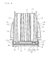
- FIG. 4 is a schematic cross sectional view taken along the IV-IV line of FIG. 3 .
- Reference numeral 1 in FIG. 1 is a heat dissipation device made of a metal, such as aluminum.
- the heat dissipation device 1 has the shape of a cylinder with a reduced diameter on one side in the axial direction of the cylinder, or a so-called shell-like shape.
- the heat dissipation device 1 has a heat transfer plate 11 in the form of a circular plate. On one surface 11a of the heat transfer plate 11, a cylindrical inner tube 12 is disposed upright concentrically with the heat transfer plate 11. The thickness of the inner tube 12 changes successively in the axial direction so that the inner tube 12 is thicker on the side adjacent to the heat transfer plate 11 and thinner on the opening-end side.
- a plurality of first fins 13, 13 ... constituting a heat dissipating section are provided over substantially the entire length of the inner tube 12 at equal intervals in the circumferential direction to protrude in radial directions.
- a cylindrical outer tube 14 is provided coaxially with the inner tube 12 to cover the inner tube 12 so that the inner tube 12 and the outer tube 14 are connected with the first fins 13, 13 ....
- These inner tube 12, outer tube 14 and first fins 13, 13 ... form a plurality of ventilation paths 15, 15 ... running in the axial direction of the inner tube 12.
- the protruding height of the first fins 13, 13 changes successively from one end of the outer tube 14 toward the opening end of the inner tube 12.
- a plurality of second fins 16, 16 ... constituting a heat dissipating section are provided over substantially the entire length of the outer tube 14 at equal intervals in the circumferential direction to protrude in radial directions.
- the protruding height of the second fins 16, 16 ... changes successively from one side in the axial direction of the outer tube 14 (the side adjacent to the heat transfer plate 11) toward the other side.
- the heat dissipation device 1 By configuring the first fins 13 and the second fins 16 so that their heights from the heat transfer plate 11 become higher successively toward the center of the heat dissipation device 1, the heat dissipation device 1 has a shell shape whose diameter is reduced successively from the side adjacent to the heat transfer plate 11 in the axial direction of the inner tube 12 toward the opening-end side.
- a plurality of third fins 17, 17 ... constituting a heat dissipating section are provided over substantially the entire length of the inner tube 12 at equal intervals in the circumferential direction to protrude in radial directions.
- the third fins 17, 17 ... are formed to face each other so that the opposing protruding ends are spaced from each other by a suitable distance.
- the distance between the opposing protruding ends of the third fins 17, 17 ... is preferably 4 cm or so.
- the optimum value of the distance between the opposing protruding ends varies according to the dimensions of the heat dissipation device 1, the amount of heat from the heat generating element, etc.
- the thickness of these fins 13, 13 ..., 16, 16 ..., and 17, 17 ... changes successively in the axial direction so that the fins are thicker on the side adjacent to the heat transfer plate 11 and thinner on the opening-end side.
- the LED modules 2, 2 ... comprise a rectangular ceramic substrate (Al 2 O 3 ), a plurality of (for example, 36) LED elements mounted densely at the center of one surface of the ceramic substrate, a sealing resin containing a dispersed fluorescent material and sealing the LED elements, and input and output terminals. It is preferable to interpose a heat transfer sheet or grease between the LED module 2, 2 ... and the heat transfer plate 11.
- a peripheral wall 11c is disposed upright on the circumferential edge of the other surface 11b of the heat transfer plate 11.
- a substantially disk-shaped reflector 3 is provided on the other surface 11b side of the heat transfer plate 11.
- the reflector 3 has a plurality of reflecting sections 31, 31 ... at positions which correspond to the LED modules 2, 2 ... when the reflector 3 is attached to the heat dissipation device 1.
- the reflector 3 protrude from one surface 3a of the reflector 3 in a direction orthogonal to the surface 3a, and include a hollow section 31a with a hole diameter substantially equal to the size of the light emitting surface of the LED modules 2, 2 ..., and an enlarged-diameter section 31b whose diameter is enlarged from one end of the hollow section 31a so that the inner diameter successively increases from the surface 3a toward the other surface 3a in the thickness direction of the reflector 3.
- the reflector 3 is made of a metal such as stainless steel, a metal coated with high reflectance paint, or an ultra fine foamed light reflecting material (for example, MCPET (registered trademark) ) having such optical properties as a high total reflectance (about 98%) and a high diffuse reflectance (about 95%).
- a peripheral wall 32 is disposed upright on the circumferential edge of the surface 3a of the reflector 3. The end face of the peripheral wall 32 is brought into contact with the end face of the peripheral wall 11c of the heat transfer plate 11, and the reflector 3 is fixed to the heat dissipation device 1 with screws etc.
- the light from the LED modules 2, 2 ... is reflected by the reflecting sections 31, 31... of the reflector 3 formed as mentioned above, the angle between light and the optical axis of the LED modules 2, 2 ... falls within a range of not greater than a predetermined angle, and the lighting device emits light whose luminous intensity distribution characteristics are controlled so that the illumination just below the lighting device is stronger.
- a cylindrical frame 4 is fitted outside the heat transfer plate 11 and the reflector 3 of the heat dissipation device 1.
- a resin cover 5 in the form of a circular plate is attached to the inner surface of the frame 4 to cover the light emitting surfaces of the LED modules 2, 2 ....
- the cover 5 is made of a polycarbonate resin.
- the lighting device configured as described above is, for example, fastened pivotably to a ceiling with a mounting tool so that the cover 5 faces downward for use as a spotlight.
- a power source unit (not shown) comprising various circuit components, such as a transformer, a resistor, and a capacitor.
- heat generated in the LED modules 2, 2 ... when the LED modules 2, 2 ... are turned on is transferred to the inner tube 12 through the heat transfer plate 11.
- the heat transferred to the inner tube 12 is conducted from the inner tube 12 to the outer tube 14 through the first fins 13, 13 .... and then transferred from the outer surface 14a of the outer tube 14 and the surfaces of the second fins 16, 16 ⁇ to the outside air, and also transferred to the air in the ventilation paths 15, 15 ... formed by the inner tube 12, outer tube 14 and first fins 13, 13 ....
- the flow rate is increased by the stack effect based on the mutual function with other neighboring heat dissipation surfaces. With an increase in the flow rate, the boundary layer becomes thinner and at the same time an increasing amount of air passes. Hence, the heat is efficiently transferred to the air flowing at an increased flow rate from the surfaces of the inner tube 12, outer tube 14 and first fins 13, 13, ... forming the ventilation paths 15, 15 ...., and heat dissipation performance is improved without increasing the external dimensions of the heat dissipation device 1.
- the ventilation path 15 functions as a medium path through which the air as a heat exchanging medium passes.
- the medium path has a structure capable of increasing the flow rate of the heat exchanging medium as mentioned above, the heat exchanging medium is spread to a part to which air is hard to flow, such as between adjacent fins and the bases of the fins, and consequently it is possible to increase the surface area of a section contributing to the heat dissipation in the heat dissipation device.
- the distance between the fins becomes shorter because of an increase in the number of fins, or a reduction in the size of the heat dissipation device, improved heat dissipation performance is achieved.
- the base of the first fin 13 is located nearest to the LED module 2 as the heat generating element, when the heat exchanging medium is spread to the base of the first fin 13 over the entire surface, the heat dissipation performance is improved more effectively.
- the heat dissipation surface area that comes into contact with air as a heat exchanging medium is increased by an amount corresponding to the surface area of the second fins 16, 16 ..., thereby improving the heat dissipation performance.
- the third fins 17, 17 ... protrude from the inner surface 12a of the inner tube 12 of the heat dissipation device 1 so that the protruding ends of the third fins 17, 17 ... face each other with a suitable space therebetween, a kind of open thermosiphon phenomenon in which the warmed air near the third fins 17, 17 ...
- the heat dissipation device 1 is configured in the shape of a cylinder with a reduced diameter on one side in the axial direction of the cylinder, or a so-called shell-like shape, and the LED modules 2, 2 ... as the heat generating elements are arranged on the other side in the axial direction of the heat dissipation device 1 (the side adjacent to the heat transfer plate 11), the heat dissipation device 1 with small external dimensions is achieved while ensuring a sufficient dissipation surface area for a part having high temperatures. Since the protruding heights of the first fins 13, 13 ... and the second fins 16, 16 ...
- the ventilation paths 15, 15 ... are formed at equal intervals in the circumferential direction of the heat dissipation device 1, if the lighting device is capable of changing the illumination direction such as a spotlight, air flows in and out of at least a part of the ventilation paths 15, 15 ..., and therefore heat from the LED modules 2, 2.... is efficiently transferred from the surfaces of the inner tube 12, outer tube 14 and first fins 13, 13 ... to the air flowing at an increased flow rate and heat dissipation performance is improved.
- the thicknesses of the inner tube 12, outer tube 14 and first fins 13, 13 ... of the heat dissipation device 1 change successively in the axial direction so that they are thicker on the side adjacent to the heat transfer plate 11 near the LED modules 2, 2 ... where the temperature is higher and thinner on the opening-end side where the temperature is relatively low, the heat transferred from the LED modules 2, 2 ... to the heat transfer plate 11 is smoothly conducted from the higher temperature side to the lower temperature side in the inner tube 12 arranged adjacent to the heat transfer plate 11, outer tube 14 and first fins 13, 13 ....
- heat dissipation performance is improved, and also the size and weight of the heat dissipation device 1 are reduced.
- the productivity is improved.
- the material for the heat dissipation device is not limited to aluminum, and metals other than aluminum may be used. It may be possible to use a resin having good heat dissipation performance. Further, the surface of the heat dissipation device is preferably coated. With coating, the heat dissipation performance is improved by radiation heat transfer, and corrosion is prevented, thereby improving the reliability of the heat dissipation device.
- the radiation heat transfer is proportional to the emissivity of the heat dissipation surface, and may be equal to or higher than convection heat transfer depending on conditions. In general, the emissivity of a metal surface is said to be between 0.1 and 0.4, and it can be increased to 0.9 or so by coating.
- coating of the heat dissipation device it is preferable to use electro-deposition coating capable of reaching the deep part, and the anodizing process is preferable.
- a lighting device is described by way of example in which it is applied to a spotlight, but the lighting device is also applicable to a downlight.
- the lighting device is placed with the cover 5 facing downward in a mounting hole provided in a ceiling, and fastened, for example, with a plate spring.
- a lighting device installed like a downlight so that the longitudinal direction of the ventilation paths 15, 15 ... is to be a vertical direction, air flows in/out of all the ventilation paths 15, 15 ..., and heat from the LED modules 2, 2 ... is transferred efficiently from the surfaces of the inner tube 12, outer tube 14 and first fins 13, 13 ... to the air flowing at an increased flow rate, thereby further improving heat dissipation performance.
- FIG. 5 is an external perspective view of a lighting device according to Embodiment 2 of the present invention.
- a lighting device according to Embodiment 2 of the present invention.
- rectangular vents 12c, 12c ... are provided at equal intervals in the circumferential direction between the first fins 13, 13 .... Since other structures are the same as those in Embodiment 1 illustrated in FIG. 1 , the corresponding component members are designated with the same reference numerals as in FIG. 1 and detailed explanations of the structures will be omitted.
- the heat dissipation device 1a By configuring the heat dissipation device 1a in the above-described manner, heat generated in the LED modules 2, 2 ... when the LED modules 2, 2 ... are turned on is transferred to the inner tube 12, and the air in the inner tube 12 is warmed. The warmed air flows out from the open end of the inner tube 12 as indicated by the arrows in FIG. 5 , while the outside air flows in from the vents 12c, 12c ... provided in the end of the inner tube 12. As a result, since the heat from the LED modules 2, 2 ... is efficiently transferred to the air as a heat exchanging medium flowing at an increased flow rate because of the stack effect in the medium path in the inner tube 12, the heat dissipation performance is further improved.
- the dimensions and number of the vents 12c, 12c ... are suitably set so as not to interfere with the heat transfer in the inner tube 12.
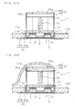
- FIG. 6 is a schematic partial cross sectional view of a lighting device according to Embodiment 3.
- a turbulence promoter 11d is formed in a protruding manner over the entire circumference to face the inner tube 11.
- the height H of the turbulence promoter 11d is preferably determined so that the relationship with distance L between the turbulence promoter 11d and the inner tube 12 satisfies a predetermined condition (L ⁇ 10H). Since other structures are the same as those in Embodiment 1 illustrated in FIG. 4 , the corresponding component members are designated with the same reference numerals as in FIG. 4 , and detailed explanations of the structures will be omitted.
- the flow of air entering the ventilation paths 15, 15 ... is disturbed by the turbulence promoter 11d and produces eddies, and flows to the vicinity of the boundary between the inner tube 12 and the heat transfer plate 11 as indicated by an arrow in FIG. 6 . Consequently, since residence of air is reduced, the heat is promptly transferred to the flowing air from the boundary where the temperature is higher as the heat from the LED modules 2, 2 ... is transferred, and heat dissipation performance is improved.
- a medium path for spreading a heat exchanging medium, such as air, to a part nearest to the LED module 2 as the heat generating element is formed.
- the protruding height of the first fins 13, 13 ... is made substantially equal to the outer tube 14, it is more preferable that the protruding height of the first fins 13, 13 ... is substantially equal to the protruding height of the second fins 16, 16 ....
- the heat dissipation device may be formed by die cast molding, or formed by an extrusion process, or a cutting process.
- FIG. 7 is an external perspective view of the lighting device according to Embodiment 4.
- FIG. 8 is a schematic side view of the lighting device
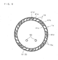
- FIG. 9 is a schematic rear view of the lighting device
- FIG. 10 is a perspective longitudinal sectional view of the lighting device.
- Reference numeral 1c in the drawings denotes a heat dissipation device made of a metal, such as aluminum.
- the heat dissipation device 1c has a cylindrical shape.
- the heat dissipation device 1c includes a heat transfer plate 11 in the form of a circular plate. On one surface 11a of the heat transfer plate 11, a cylindrical heat dissipating tube 18 is fitted externally and concentrically on the heat transfer plate 11.
- a plurality of fins 19, 19 ... are formed over substantially the entire length in the axial direction of the heat dissipating tube 18 at equal intervals in the circumferential direction.
- the fins 19, 19 ... have a so-called involute axial cross section in which the fins 19, 19 ... extend in radial directions and are successively curved in a circumferential direction from the inside toward the outside in the radial direction.
- a plurality of (six in the drawing) LED modules 2, 2 ... are mounted at equal intervals in the circumferential direction.
- a substantially disk-shaped reflector 3 is provided on the other surface 11b of the heat transfer plate 11.
- a plurality of reflecting sections 31, 31 ... are formed at positions which correspond to the LED modules 2, 2 ... when the reflector 3 is attached to the heat dissipation device 1c. Since the LED modules 2, 2 ... and the reflector 3 are the same as those in Embodiment 1, detailed explanations thereof will be omitted.
- a peripheral wall 32 is disposed upright on the circumferential edge of the one surface 3a of the reflector 3. The end face of the peripheral wall 32 is brought into contact with the circumferential edge of the heat transfer plate 11 and the end face of the heat dissipating tube 18, and the reflector 3 is fixed to the heat dissipation device 1c with screws etc.
- the frame 41 comprises a ring section 41a, a cylindrical outer wall 41b disposed upright on the outer circumferential edge of the ring section 41a, and a substantially cylindrical inner wall 41c disposed upright on the inner circumferential edge of the ring section 41a.
- a plurality of (eight in the drawing) slits 41d, 41d ... are formed at equal intervals in the circumferential direction between the outer wall 41b and the inner wall 41c of the ring section 41a.
- the inner wall 41c of the frame 41 is externally fitted on the reflector 3.
- a resin cover 5 in the shape of a circular plate is attached to the inner surface of the ring section 41a of the frame 41 to cover the light emitting surfaces of the LED modules 2, 2 ....
- the cover 5 is made of, for example, a polycarbonate resin.
- the slits 41d, 41d ... are formed to pass through substantially the center in the radial direction of the fins 19, 19 ... when the frame 41 is attached to the heat dissipation device 1c, and function as vents.
- a power source unit 6 is mounted inside the heat dissipating tube 18.
- the power source unit 6 comprises two partial power source units 61 and 62.
- Spread in these partial power source units 61 and 62 are various circuit components constituting a full wave rectifier section for rectifying an alternate current to a direct current, a constant current section for maintaining the forward current of the LED modules 2, 2 ... constant, a control section for controlling the switching of the LED modules 2, 2 ..., etc.
- a substrate 60 on which the power source unit 6 is mounted is attached to a mounting plate 7 comprising a rectangular flat plate 71, and a peripheral wall 72 extending from the peripheral edge of the flat plate 71 in an orthogonal direction.
- the space between the substrate 60 and the mounting plate 7 is filled with a resin 8.
- the resin 8 is an elastic heat resisting resin with excellent heat transfer performance, and, for example, a silicone resin containing filler.
- the mounting plate 7 is attached so that the peripheral wall 72 is in contact with the inner surface 18b of the heat dissipating tube 18 and the one surface 11a of the heat transfer plate 11.
- heat generated by the power source unit 6 is transferred to the mounting plate 7 through the resin 8, transferred from the mounting plate 7 to the heat dissipating tube 18, and then transferred to the outside air as to be described later.
- a rise in the temperature of the power source unit 6 is reduced, thereby preventing problems caused by the temperature rise.
- a cover 9 having a circular plate 91 and a cylinder 92 mounted upright on the circumferential edge of the circular plate 91. With this cover 9, the space inside the heat dissipating tube 18 is closed. Connection terminals 93, 93 are provided on the outer surface of the circular plate 91. The connection terminals 93, 93 are connected to the power source unit 6 through lead wires (not shown).
- the lighting device thus configured is placed with the cover 5 facing downward, and fastened to a mounting hole formed in a ceiling with, for example, a plate spring.
- heat generated in the LED modules 2, 2 ... when the LED modules 2, 2 ... are turned on is transferred to the heat dissipating tube 18 through the heat transfer plate 11.
- the heat transferred to the heat dissipating tube 18 is conducted from the heat dissipating tube 18 to the fins 19, 19 ..., and transferred from the surfaces of the heat dissipating tube 18 and fins 19, 19 ... to the air.
- the air in the ventilation paths 15a, 15a ... covered by the heat dissipating tube 18 and fins 19, 19 ... is warmed by the transferred heat and flows out from the upper end of the ventilation paths 15a, 15a ... of the lighting device, while the outside air flows in from the slits 41d, 41d ...
- the air in the ventilation paths 15a, 15a ... has a higher temperature on the lower side where the LED modules 2, 2 ... as the heat generating elements are mounted and has a lower temperature on the upper side, and therefore the flow rate is increased by the stack effect.
- the heat is efficiently transferred to the air flowing at an increased flow rate from the surfaces of the heat dissipating tube 18 and fins 19, 19 ... forming the ventilation paths 15a, 15a ..., and heat dissipation performance is improved without increasing the external dimensions of the heat dissipation device 1c.
- the power source unit 6 is stored inside the heat dissipation device 1c, it is possible to reduce the size of the lighting device.
- the heat dissipation surface area of the fins 19, 19 ... attached to the heat dissipating tube 18 of the heat dissipation device 1c is increased by an amount corresponding to the portions curved in the circumferential direction, the heat dissipation performance is improved.
- the air as a heat exchanging medium passing in the ventilation path 15a as the medium path dissipates the heat transferred from the heat generating element by the heat dissipating fins.
- the fins are involute type fins, the contact surface area of the heat dissipating section with the heat exchanging medium is increased, and the heat exchanging medium is spread over the entire surface, thereby more effectively improving the heat dissipation performance.
- the fins 19, 19 ... have a so-called involute axial cross section
- the fins 19, 19 ... are not limited to the involute form as long as they are curved in the circumferential direction while maintaining substantially an equal distance between the fins 19, 19 ... from the base to the tip.
- the heat dissipating tube 18 of the heat dissipation device 1c has the fins 19, 19 ... having a so-called involute axial cross section in which they extend in radial directions from the outer surface 18a of the heat dissipating tube 18 and are successively curved in a circumferential direction from the inside toward the outside in the radial direction, but it is possible to form the fins into different shapes.
- FIG. 11 is a view schematically illustrating fins in another shape.
- rectangular fins 19a, 19a ... are formed over substantially the entire length of the heat dissipating tube 18 to protrude in radial directions from the outer surface 18a of the heat dissipating tube 18. Since other structures are the same as those of the lighting device illustrated in Embodiment 4, drawings and explanations thereof will be omitted.
- the heat dissipation surface area is increased by an amount corresponding to the fins 19a, 19a..., and therefore heat dissipation performance is improved.
- the heat dissipation device 1d is configured in a simple form, it is easy to manufacture the heat dissipation device 1d.
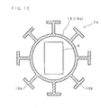
- FIG. 12 is a view schematically illustrating fins in other shape.
- fins 19b, 19b ... are formed over substantially the entire length in the axial direction of the heat dissipating tube 18 at equal intervals in the circumferential direction.
- Each fin 19b extends in a radial direction from the outer surface 18a of the heat dissipating tube 18 and protrudes from the extended end to both sides in substantially the circumferential direction of the outer tube so that the fin 19 has a T-shaped axial cross section. Since other structures are the same as those of the lighting device illustrated in Embodiment 4, drawings and explanations thereof will be omitted.
- the heat dissipation surface area of the fins 19b, 19b ... provided on the heat dissipating tube 18 of the heat dissipation device 1e is increased by an amount corresponding to the portions protruding to both sides in substantially the circumferential direction of the heat dissipating tube 18, and therefore heat dissipation performance is further improved.
- the fins 19b, 19b ... having a T-shaped axial cross section are formed, they are not limited to this, and may be formed, for example, with a Y-shaped axial cross section.
- FIG. 13 is a view schematically illustrating fins in other shape.
- a heat dissipating tube 18 of a heat dissipation device If, a plurality of rectangular fins 19c, 19c ... are arranged in a spiral form. Since other structures are the same as those of the lighting device illustrated in Embodiment 4, drawings and explanations thereof will be omitted.
- the rectangular fins 19c, 19c ... are provided in a spiral form on the heat dissipating tube 18, the fins just need to be formed to be able to maintain good heat dissipation performance irrespective of the mount direction of the heat dissipation device If, and, for example, it is possible to form a plurality of pin-like fins on the heat dissipating tube.
- a heat dissipation device by changing the thickness of the heat dissipating tube 18 and fins of the heat dissipation device successively in the axial direction so that the heat dissipating tube 18 and fins are thicker on the side adjacent to the heat transfer plate 11, which is located near the LED modules 2, 2 ... and has a higher temperature, and thinner on the opening-end side where the temperature is relatively low.
- FIG. 14 is a view schematically illustrating a heat transfer structure of the power source unit 6. This embodiment is explained by way of an example applied to a lighting device according to Embodiment 5.
- a metallic heat transfer plate 7a in the form of a rectangular plate slightly larger than the substrate on which the power source unit 6 is mounted.
- the heat transfer plate 7a is parallel to the axis of the heat dissipating tube 18 and connected to the inner surface 18b of the heat dissipating tube 18 at two opposite side edges.
- the power source unit 6 is arranged to face the heat transfer plate 7a with a space between them.
- the power source unit 6 and the heat transfer plate 7a are preferably arranged as close as possible while ensuring a safe distance to prevent discharge from the circuit components of the power source unit 6 to the heat transfer plate 7a, and, for example, they are spaced apart from each other by 5 mm. Since other structures are the same as those of the lighting device illustrated in Embodiment 5, the corresponding structural members are designated with the same reference numerals as in FIG. 11 , and the detailed explanations of the structures will be omitted.
- heat generated by the power source unit 6 is transferred through air as a heat exchanging medium to the heat transfer plate 7a arranged close to the power source unit 6, and then transferred from the heat transfer plate 7a to the outside air through the heat dissipating tube 18.
- a rise in the temperature of the power source unit 6 is controlled, and problems caused by the temperature rise are prevented.
- FIG. 15 is a view schematically illustrating another heat transfer structure of the power source unit. This embodiment is also explained by way of an example applied to a lighting device according to Embodiment 5.
- a metallic heat transfer plate 7b having a rectangular plate 71b slightly larger than the substrate on which the power source unit 6 is mounted, and side walls 72b, 72b formed upright on two opposite side edges of the rectangular plate 71b.
- the rectangular plate 71b is parallel to the axis of the heat dissipating tube 18 and, as illustrated in FIG. 15 , connected to the inner surface 18b of the heat dissipating tube 18 at two opposite side edges of each of the rectangular plate 71b and side walls 72, 72.
- the power source unit 6 is arranged to face the respective rectangular plate 71b and side walls 72b, 72b of the heat transfer plate 7b with a space between them.
- the space between the power source unit 6 and the heat transfer plate 7b is filled with a resin 8.
- the resin 8 is an elastic heat resistant resin with excellent heat transfer performance, and, for example, a silicone adhesive containing filler. Since other structures are the same as those of the lighting device illustrated in Embodiment 5, the corresponding structural members are designated with the same reference numerals as in FIG. 11 , and the detailed explanation of the structures will be omitted.
- heat generated by the power source unit 6 is transferred to the heat transfer plate 7b through the resin 8 and then transferred from the heat transfer plate 7b to the outside air through the heat dissipating tube 18.
- the presence of the resin 8 in place of an air layer in the gap reduces the heat resistance, thereby further reducing a temperature rise in the power source unit 6 and preventing problems caused by the temperature rise.
- the heat dissipation devices according to Embodiments 4 to 9 described above may be formed by die cast molding, or formed by an extrusion process, or a cutting process. From the point of view of optimizing the heat dissipating design and manufacturability of the heat dissipation devices, it is more preferable to form the main body of the heat dissipation device excluding the heat transfer plate by an extrusion process and then braze or weld the heat dissipation device main body and the heat transfer plate.
- a heat dissipation device comprises a heat transfer plate, a tube disposed upright on the heat transfer plate, and a plurality of fins formed radially on the tube to extend in directions crossing the tube
- FIG. 16 is an external perspective view of a heat dissipation device 1i
- FIG. 17 is a schematic sectional view of a lighting device having the heat dissipation device 1i.
- the heat dissipation device 1i illustrated in FIG. 17 shows a cross section taken along the XVII-XVII line of FIG. 16 .
- the heat dissipation device 1i includes a heat transfer plate 11 in the form of a circular plate. On one surface 11a of the heat transfer plate 11, a plurality of (four in FIG. 16 ) rectangular heat dissipating plates 21, 21 ... are disposed upright parallel to each other. On the surface 11a of the heat transfer plate 11, a link plate 22 is disposed upright so that it runs through substantially the center of the plurality of heat dissipating plates 21, 21 ... and crosses the heat dissipating plates 21, 21 ... at right angles.
- a plurality of LED modules 2, 2 ... are mounted on the other surface 11b of the heat transfer plate 11.
- a substantially disk-shaped reflector 3 is provided on the surface 11b of the heat transfer plate 11.
- a plurality of reflecting sections 31, 31 ... are formed at positions which correspond to the LED modules 2, 2 ... when the reflector 3 is attached to the heat dissipation device 1i. Since the LED modules 2, 2 ... and the reflector 3 are the same as those in Embodiment 1, detailed explanations thereof will be omitted.
- a frame 42 On a side of the heat dissipation device 1i, adjacent to the heat transfer plate 11, a frame 42 is provided.
- the frame 42 comprises a ring section 42a, and a cylindrical peripheral wall 42b disposed upright on the inner circumferential edge of the ring section 42a.
- the peripheral wall 42b of the frame 42 is externally fitted on the reflector 3.
- a resin cover 5 in the shape of a circular plate is attached to the inner surface of the ring section 42a of the frame 42 to cover the light emitting surfaces of the LED modules 2, 2 ....
- the cover 5 is made of a polycarbonate resin.
- the lighting device thus configured is placed with the cover 5 facing downward and fastened pivotably in a mounting hole formed in a ceiling 100, for example, with a plurality of plate springs, for use as a so-called downlight.
- the plate springs are appropriately arranged to evenly support the weight of the downlight.
- the lighting device is light, two plate springs are sufficient.
- the weight of the lighting device exceeds 1 kg, if only two plate springs are used, they may damage the mounting hole in the ceiling, and therefore it is more preferable to fasten the lighting device with three plate springs.
- a power source unit (not shown) is provided outside the lighting device.
- heat generated in the LED modules 2, 2 ... when the LED modules 2, 2 ... are turned on is transferred to the heat dissipating plates 21, 21 ... and the link plate 22 through the heat transfer plate 11.
- the air near the heat dissipating plates 21, 21 ... and the link plate 22 is warmed by the transferred heat and flows out in an upward direction along the heat dissipating plates 21, 21 ... and the link plate 22, while the outside air flows in as a heat exchanging medium from the lower end side of the heat dissipating plates 21, 21 ... and the link plate 22.
- the heat transfer plate 11, heat dissipating plates 21 and link plate 22 constitute a medium path.
- link plate 22 If the link plate 22 is not present, low-temperature air flowing from both sides causes convection by the heat conducted and transferred from the heat transfer plate 11 and heat dissipating plates 21, and naturally flows upward while causing collisions or eddies between the fins. On the other hand, if the link plate 22 is present, since a surface of the link plate also functions as a heat dissipation surface, an air flow rising along this surface is produced, and therefore an air flow entering from a side and rising upward at the center (an air flow passing through the medium path) is rectified and accelerated.
- the link plate 22 also performs the function of reinforcing neighboring fins. In particular, for die cast molding, a curve caused after releasing from the mold is reduced.
- the link plate 22 is arranged to pass through substantially the center of a plurality of heat dissipating plates 21, 21 ..., it may be formed to avoid the center of the heat transfer plate 11 as illustrated in FIG. 18 , and a through-hole 11e for wiring may be formed in the center of the heat transfer plate 11.
- the through-hole 11e for wiring provided in the center of the heat transfer plate 11 facilitates wiring to the LED modules 2, 2 ....
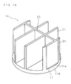
- FIG. 19 is a view schematically illustrating other form of heat dissipation device 1k
- FIG. 20 is a view schematically illustrating a positional relationship between the heat dissipation device 1k and the power source unit 6.
- the heat dissipation device 1k includes a heat transfer plate 11 in the form of a circular plate. On one surface 11a of the heat transfer plate 11, a plurality of (four in the drawing) rectangular heat dissipating plates 21, 21 ... are disposed upright to be parallel to each other. On the surface 11a of the heat transfer plate 11, a link plate 23 for connecting the plurality of heat dissipating plates 21, 21 ... is disposed upright. The link plate 23 is arranged so that it crosses the heat dissipating plates 21, 21 ... at right angles at a position nearer to the circumferential edge rather than the center of the heat transfer plate 11. As illustrated in FIG.
- the power source unit 6 is positioned on the opening-end side of the heat dissipation device 1k so that a part of the power source unit 6 faces the heat dissipation device 1k. Since other structures are the same as those of the lighting device illustrated in Embodiment 10, drawings and explanations thereof will be omitted.
- heat generated in the LED modules 2, 2 ... when the LED modules 2, 2 ... are turned on is transferred to the heat dissipating plates 21, 21 ... and the link plate 23 through the heat transfer plate 11.
- the air near the heat dissipating plates 21, 21 ... and the link plate 23 is warmed by the transferred heat and flows out in an upward direction along the heat dissipating plates 21, 21 ... and the link plate 23, while the outside air flows in from the lower end side of the heat dissipating plates 21, 21 ... and link plate 23.
- the power source unit 6 is arranged so that it partially faces the heat dissipation device 1k, the external dimension in the diameter direction of the lighting device is decreased, and the size of the lighting device is reduced. Further, since the power source unit 6 is provided at a position distant from the neighborhood of the link plate 23 where a main stream of rising current passes when the warmed air rises along the heat dissipating plates 21, 21 ... and link plate 23, the influence of heat on the circuit components constituting the power source unit 6 is reduced.
- link plate 23 is mounted at a position closer to the circumferential edge rather than the center of the heat transfer plate 11, it is possible to form a through-hole for wiring in the center of the heat transfer plate 11, thereby facilitating wiring to the LED modules 2, 2 ....
- FIG. 21 is an external perspective view of other form of heat dissipation device 1m
- FIG. 22 is a view schematically illustrating the positional relationship between the heat dissipation device 1m and the power source unit 6.
- the heat dissipation device 1m includes a heat transfer plate 11 in the form of a circular plate. On one surface 11a of the heat transfer plate 11, a plurality of (four in the drawing) rectangular heat dissipating plates 24, 24 ... are disposed upright to be parallel to each other. In one corner on a side of each of the heat dissipating plates 24, 24 ... opposite to the heat transfer plate 11, recessed portions 24a, 24a ... are formed. With these recessed portions 24a, 24a ..., a substantially rectangular parallelepiped space is formed on one side of the opening-end side of the heat dissipation device 1m.
- a link plate 23 for connecting the plurality of heat dissipating plates 24, 24 ... is disposed upright at a position closer to the peripheral side rather than the center of the heat transfer plate 11.
- the link plate 23 is arranged so that it crosses the heat dissipating plates 24, 24 ... at right angles on a side opposite to the side where the recessed portions 24a, 24a ... are formed.
- the power source unit 6 is provided so that a part of the power source unit 6 is placed in the space formed by the recessed portions 24a, 24a ... of the heat dissipation device 1m.
- the power source unit 6 has a heat dissipation device cover 65 which faces the heat dissipation device 1m with a suitable distance between them and covers the opening end side of the heat dissipation device 1m.
- a heat dissipation device cover 65 which faces the heat dissipation device 1m with a suitable distance between them and covers the opening end side of the heat dissipation device 1m.
- heat generated in the LED modules 2, 2 ... when the LED modules 2, 2 ... are turned on is transferred to the heat dissipating plates 24, 24 ... and the link plate 23 through the heat transfer plate 11.
- the air near the heat dissipating plates 24, 24 ... and the link plate 23 is warmed by the transferred heat and flows out in an upward direction along the heat dissipating plates 24, 24 ... and the link plate 23, while the outside air flows in from the lower end side of the heat dissipating plates 24, 24 ... and the link plate 23.
- the heat dissipation device 1m By configuring the heat dissipation device 1m in such a manner, a sufficient heat dissipation surface area is ensured and heat dissipation performance is improved without increasing the external dimensions of the heat dissipation device 1m. Moreover, since the power source unit 6 is disposed so that a part of the power source unit 6 is positioned in the space formed by the recessed portions 24a, 24a ... of the heat dissipation device 1m, the size of the lighting device is further reduced.
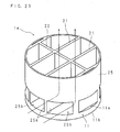
- FIG. 23 is an external perspective view of other form of heat dissipation device In.
- the heat dissipation device In includes a heat transfer plate 11 in the form of a circular plate. On one surface 11a of the heat transfer plate 11, a plurality of (four in FIG. 23 ) rectangular heat dissipating plates 21, 21 ... are disposed upright to be parallel to each other. On the surface 11a of the heat transfer plate 11, a link plate 22 is disposed upright so that it passes through substantially the center of the plurality of heat dissipating plates 21, 21 ... and crosses the heat dissipating plates 21, 21 ... at right angles.
- a heat dissipating tube 25 is arranged concentrically with the heat transfer plate 11 to enclose the heat dissipating plates 21, 21 ... and link plate 22.
- the heat dissipating tube 25 is a cylinder having substantially the same diameter as that of the heat transfer plate 11 and separated by a suitable distance from the heat transfer plate 11. In this structure, vents 25a, 25a ... for allowing an inflow of outside air are formed between the heat transfer plate 11 and the heat dissipating tube 25. Since other structures are the same as those of the lighting device illustrated in Embodiment 10, the drawings and explanations thereof will be omitted.
- heat generated in the LED modules 2, 2 ... when the LED modules 2, 2 ... are turned on is transferred to the heat dissipating plates 21, 21 ... and the link plate 22 through the heat transfer plate 11, conducted from the heat dissipating plates 21, 21 ... to the heat dissipating tube 25 and then transferred from the surface of the heat dissipating tube 25 to the outside air as well as to the air in the ventilation paths 25b, 25b ... formed by the heat dissipating plates 21, 21 ..., link plate 22 and heat dissipating tube 25.
- the heat dissipating plates 21, 21 ..., link plate 22 and heat dissipating tube 25 As indicated by the arrows in FIG.
- the air in the ventilation paths 25b, 25b is warmed by the transferred heat and flows out from the upper ends of the ventilation paths 25b, 25b ... along the heat dissipating plates 21, 21 ..., link plate 22 and heat dissipating tube 25, while the outside air as a heat exchanging medium flows in from the vents 25a, 25a ....
- the heat dissipation surface area is increased without increasing the external dimensions of the heat dissipation device In, and the heat transferred from the LED modules is efficiently transferred from the surfaces of the heat dissipating plates 21, 21 ..., link plate 22 and heat dissipating tube 25 constituting the ventilation paths 25b, 25b ... as medium paths to the air flowing at an increased flow rate because of the stack effect.
- the heat dissipation performance is improved without increasing the external dimensions of the heat dissipation device In.
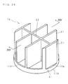
- FIG. 24 is an external perspective view of other form of heat dissipation device 1p
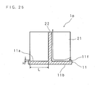
- FIG. 25 is a schematic cross sectional view of the heat dissipation device 1p taken along the XXV-XXV line of FIG. 24 .
- the heat dissipation device 1p includes a heat transfer plate 11 in the form of a circular plate.
- a plurality of (four in FIG. 24 ) rectangular heat dissipating plates 21, 21 ... are disposed upright to be parallel to each other.
- a link plate 22 is disposed upright so that it passes through substantially the center of the plurality of heat dissipating plates 21, 21 ... and crosses the heat dissipating plates 21, 21 ... at right angles.
- a protruding turbulence promoter 11f is formed over substantially the entire circumference to face the link plate 22.
- the height H of the turbulence promoter 11f is preferably determined so that the relationship with distance L between the turbulence promoter 11f and the link plate 22 satisfies a predetermined condition (L ⁇ 10H). Since other structures are the same as those of the lighting device illustrated in Embodiment 10, the drawings and explanations thereof will be omitted.
- FIG. 26 is an external perspective view of other form of heat dissipation device 1q
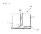
- FIG. 27 is a schematic cross sectional view of the heat dissipation device 1q taken along the XXVII-XXVII line of FIG. 26 .
- the heat dissipation device 1q includes a heat transfer plate 111 in the form of a circular plate. On one surface 111a of the heat transfer plate 111, a plurality of (four in FIG. 26 ) rectangular heat dissipating plates 21, 21 ... are disposed upright to be parallel to each other. On the surface 111a of the heat transfer plate 111, a link plate 22 is disposed upright so that it passes through substantially the center of the plurality of heat dissipating plates 21, 21 ... and crosses the heat dissipating plates 21, 21 ... at right angles. As illustrated in the drawing, the surface 111a of the heat transfer plate 111 is formed as an inclined surface slanting upward from the circumferential edge of the heat transfer plate 111 toward the link plate 22. Since other structures are the same as those of the lighting device illustrated in Embodiment 10, the drawings and explanations thereof will be omitted.
- the air entering the heat dissipation device 1q flows to the vicinity of the boundary between the link plate 22 and the heat transfer plate 111 along the inclined surface (one surface 111a) of the heat transfer plate 11.
- the heat is promptly transferred to the air flowing from the boundary where the temperature is higher due to the heat transferred from the LED modules, and heat dissipation performance is improved.
- a boundary section 112 between the heat transfer plate 111 and the link plate 22 and/or the boundary between the heat transfer plate 111 and the heat dissipating plate 21 may be rounded.
- the boundary is rounded, similarly to the above-mentioned inclined surface, it is possible to supply the heat exchanging medium to a part near the boundary where the flow rate is low and air tends to reside, and therefore heat dissipation performance is improved.
- the heat dissipation devices according to Embodiments 10 to 15 described above may be formed by die cast molding, or formed by an extrusion process, or a cutting process. From the point of view of optimizing the heat dissipating design and manufacturability of heat dissipation devices, it is more preferable to form the main body of a heat dissipation device excluding a heat transfer plate by an extrusion process and then braze or weld the heat dissipation device main body and the heat transfer plate. When the heat dissipation performance is sufficient, the flat planes may be just fastened together with screws.
- heat dissipation device it is also preferable to form a heat dissipation device so that the heat dissipating plates and the link plate of the heat dissipation device are thicker on the side adjacent to the heat transfer plate 11 near the LED modules 2, 2 ... where the temperature is higher and thinner on the opening-end side where the temperature is relatively low.
- FIG. 29 is an external perspective view of the rectifying cap.
- the rectifying cap 97 comprises a circular plate 95 having a circular opening 95a, and a cylinder 96 disposed upright on the circumferential edge of the circular plate 95.
- the cylinder 96 has a plurality of rectangular vents 96a, 96a ... formed on a side adjacent to the circular plate 95.
- FIG. 30A and FIG. 30B illustrate an example of application of the rectifier cap 97 in which the rectifier cap 97 is applied to the heat dissipation device 1i according to Embodiment 10.
- the rectifier cap 97 is configured so that when it is put over the heat dissipation device 1i, the opening end of the cylinder 96 is spaced by a suitable distance from the heat transfer plate 11 of the heat dissipation device 1i.
- the heat dissipating plates 21, 21 ..., link plate 22 of the heat dissipation device 1i and rectifier cap 97 form ventilation paths.
- heat generated in the LED modules 2, 2 ... when the LED modules 2, 2 ... are turned on is transferred to the heat dissipating plates 21, 21 ... and the link plate 22 through the heat transfer plate 11.
- the air near the heat dissipating plates 21, 21 ... and the link plate 22 is warmed by the heat transferred from the LED modules 2, 2 ... and flows upward along the heat dissipating plates 21, 21 ... and the link plate 22 to flow out mainly from the opening 95a of the rectifier cap 97, while the outside air flows into the ventilation paths from the gap between the rectifier cap 97 and the heat transfer plate 11.
- the air in the ventilation paths has a higher temperature on the lower side where the LED modules 2, 2 ... as the heat generating elements are mounted and a lower temperature on the upper side, the flow rate is increased by the stack effect.
- the heat is efficiently transferred from the surfaces of the heat dissipating plates 21, 21 ... and link plate 22 constituting the ventilation paths to the air flowing at an increased flow rate, and heat dissipation performance is improved without increasing the external dimensions of the heat dissipation device 1i.
- the edges of the heat dissipating plates 21, 21 ... and link plate 22 are covered with the rectifier cap 97, it is possible to prevent a worker assembling the lighting device from being injured by contact with the edges of the heat dissipating plates 21, 21 ... and link plate 22, and also prevent the edges of the heat dissipating plates 21, 21 ... and link plate 22a from damaging the building materials by contact.
- vents 96a, 96a ... are formed in the cylinder 96 of the rectifier cap 97 at equal intervals in the circumferential direction, even when the opening 95a of the rectifier cap 97 is covered with a heat insulating material 110 as illustrated in FIG. 30B , at least some of the vents 96a, 96a ... of the rectifier cap 97 are not covered with the heat insulating material 110 and ensure ventilation, thereby allowing the air warmed by the heat transferred from the surfaces of the heat dissipating plates 21, 21 ... and link plate 22 to flow out from the vents 96a, 96a ....
- the turbulence promoter in the form of a cylinder is provided in a protruding manner over substantially the entire circumference of the circumferential edge of the heat transfer plate, it is not limited to this. It may be possible to form a plurality of protrusions on the circumferential edge of the heat transfer plate at suitable intervals in the circumferential direction.
- a heat dissipation device is fabricated in the form of a shell or a cylinder, it is not limited to this, and may be fabricated in the shape of, for example, a prism.
- the heat dissipation device also functions as a supporting member for the light source, a separate member may be provided as the supporting member.
- the LED modules 2, 2 ... in which a plurality of LED elements are mounted are used as the light source, the light source is not limited to them, and it may be possible to use a plurality of LED elements, other types of LEDs, EL (Electro Luminescence) etc.
- the above embodiments illustrate examples in which heat dissipation devices with improved heat dissipation performance are applied to lighting devices with a narrow irradiation range, such as a spotlight and a downlight
- the applications of the heat dissipation devices are not limited to such lighting devices, and the heat dissipation devices may be applied to other types of lighting devices, and equipment having heat generating elements other than lighting devices.
- the present invention may be implemented in various modified forms within the scope of the claims.
Landscapes
- Engineering & Computer Science (AREA)
- General Engineering & Computer Science (AREA)
- Physics & Mathematics (AREA)
- Geometry (AREA)
- Arrangement Of Elements, Cooling, Sealing, Or The Like Of Lighting Devices (AREA)
- Non-Portable Lighting Devices Or Systems Thereof (AREA)
Abstract
Description
- The present invention relates to a heat dissipation device for dissipating heat from a heat generating element to the outside by natural convection, and also relates to a lighting device having the heat dissipation device.
- In general, a lighting device contains therein heat generating components (heat generating elements) such as a light source and power source circuit components. Therefore, the lighting device needs to be configured so that a rise in the temperatures of the heat generating elements stored inside is reduced to ensure the performance of the heat generating components and a rise in the outside temperature of the lighting device is also reduced from the safety point of view. In particular, in a lighting device using a light emitting diode (hereinafter referred to as the LED) as a light source, a rise in the temperature of the LED may shorten the life of the LED and cause poor light emitting efficiency and a problem of difficulty in obtaining a necessary amount of light. Thus, in order to reduce the rise in the temperature of the LED, it is necessary to configure a structure capable of satisfactorily dissipating heat.
- Moreover, some lighting devices, such as a spotlight and a downlight, have a high-output light source that emits light with high intensity, and therefore they include a heat dissipation device to dissipate heat generated by the light source to the outside (see, for example, Patent Document 1).
- The downlight disclosed in
Patent Document 1 comprises a lamp as a heat generating element; a fixture body which stores the lamp therein, has a light-transmitting aperture and is mounted in a hollow opening in a ceiling at the opposite side to the light-transmitting aperture; and a plurality of fins provided as a heat dissipation device over a suitable length in a vertical direction of the fixture body to protrude in radial directions. In this structure, heat emitted by the lamp is transferred to a plurality of fins through the fixture body and dissipated from the surfaces of the fins into the air. - Patent Document 1: Japanese Patent Application Laid Open No.
H09-293410 (1997 - For lighting devices such as spotlights and downlights, especially there is a demand for increasing the output of the light source while reducing the size of the lighting device. In particular, since a downlight is installed from the room side, the external dimensions are limited by the size of a mounting hole, and the height is also limited by the space above the ceiling. It is therefore necessary to improve the heat dissipation performance without increasing the external dimensions of the heat dissipation device. For a lighting device comprising fins protruding in radial directions like the downlight disclosed in
Patent Document 1, it is considered to increase the number of fins in order to expand the heat dissipation surface area without changing the external dimensions of the heat dissipation device. However, when the number of fins is increased, the space between the fins, particularly the space between the bases of the fins becomes narrower, the air is hard to flow to the vicinity of the bases of the fins where temperature is higher, and consequently there is a possibility that sufficient heat transfer from the fins to air is not achieved. - The present invention has been made to solve the above problems, and it is an object of the invention to provide a heat dissipation device capable of improving the heat dissipation performance by spreading out a heat exchanging medium, such as air, without increasing its external dimensions, and to provide a lighting device having the heat dissipation device.
- A heat dissipation device according to the present invention is a heat dissipation device for dissipating heat generated by a heat generating element, such as a light source, characterized by comprising a medium path for spreading a heat exchanging medium, such as air, to a part of a heat dissipating section to which the heat from the heat generating element is transferred, the part being nearest to the heat generating element.
- In the present invention, since the heat exchanging medium is spread to a part of the heat dissipating section such as a fin to which the heat from the heat generating element is transferred, the part being nearest to the heat generating element, the heat dissipation performance is improved without increasing the external dimensions of the heat dissipation device.
- A heat dissipation device according to the present invention is a heat dissipation device for dissipating heat generated by a heat generating element, such as a light source, through a medium, such as air, from a heat dissipating section to which the heat from the heat generating element is to be transferred, characterized by comprising a medium path for improving heat dissipation performance by reducing residence of air warmed by the heat from the heat generating element, or by increasing a flow rate of natural convection.
- In the present invention, since residence of air is reduced or the flow rate is increased by adjusting a flow of air as a heat exchanging medium around the heat dissipating section, such as a fin, to which the heat from the heat generating element is transferred, the heat dissipation performance is improved without increasing the external dimensions of the heat dissipation device.
- A heat dissipation device according to the present invention is characterized in that the medium path is constituted by an inner tube, an outer tube covering the inner tube, and a fin provided between the inner tube and the outer tube.
- In the present invention, the medium path is constituted by the inner tube, the outer tube covering the inner tube, and the fin between the inner tube and the outer tube. By appropriately configuring the heat generating element and the heat dissipation device, the heat dissipation surface area is increased and also the flow rate of air flowing through the medium path formed by the inner tube, the outer tube and the fin is increased by a stack effect, and therefore heat dissipation performance is improved without increasing the external dimensions of the heat dissipation device.
- A heat dissipation device according to the present invention is a heat dissipation device for dissipating heat generated by a heat generating element to outside, characterized by comprising: an inner tube to which the heat from the heat generating element is to be transferred; a fin protruding from an outer surface of the inner tube in a direction crossing the outer surface; and an outer tube disposed to cover the inner tube.
- In the present invention, the fin protruding from the outer surface of the inner tube in a direction crossing the outer surface are formed on the inner tube to which the heat from the heat generating element is transferred, and the outer tube is disposed to cover the inner tube. By providing the inner tube, outer tube and fin in such a manner, the heat dissipation surface area is increased and heat dissipation performance is improved without increasing the external dimensions of the heat dissipation device. Moreover, by appropriately mounting the heat generating element and the heat dissipation device, the flow rate of air flowing through the medium path formed by the inner tube, outer tube and fins is increased by the stack effect, and heat dissipation performance is improved.
- A heat dissipation device according to the present invention is characterized by further comprising a fin protruding from an outer surface of the outer tube.
- In the present invention, since the fin is provided to protrude from the outer surface of the outer tube, the heat dissipation surface area is increased by an amount corresponding to the surface area of the fin, and heat dissipation performance is further improved.
- A heat dissipation device according to the present invention is characterized by further comprising a fin protruding from an inner surface of the inner tube.
- In the present invention, since the fin is provided to protrude from the inner surface of the inner tube, the heat dissipation surface area is increased by an amount corresponding to the surface area of the fin, and heat dissipation performance is further improved. In addition, by providing a plurality of the fin so that the fins face each other with a suitable distance between the protruding ends of the fins, it is possible to promote a kind of open thermosiphon phenomenon in which the warmed air near the fins flows out, while air flows into the space between the opposing protruding ends of the fins, enabling efficient heat transfer from the surfaces of the fins to the air.
- A heat dissipation device according to the present invention is characterized in that the inner tube is provided with a vent for allowing air to pass through an interior of the inner tube.
- In the present invention, since the inner tube is provided with a vent for allowing the air to pass through the interior of the inner tube, if the heat generating element and the heat dissipation device are appropriately mounted, the flow rate of air flowing in the inner tube is increased by the stack effect, and heat dissipation performance is further improved.
- A heat dissipation device according to the present invention is characterized in that the heat dissipation device has substantially a shell shape with a reduced diameter on one side in an axial direction of the inner tube.
- In the present invention, the heat dissipation device is formed in the shape of substantially a shell with a reduced diameter on one side in the axial direction of the inner tube. By mounting the heat generating element on the other side in the axial direction of the inner tube of the heat dissipation device, it is possible to achieve small external dimensions of the heat dissipation device while ensuring a sufficient heat dissipation surface area for a part having a high temperature.
- A heat dissipation device according to the present invention is characterized by further comprising: a heat transfer plate on which the inner tube is disposed upright and to which the heat from the heat generating element is to be transferred; and a turbulence promoter for disturbing a flow of air, the turbulence promoter being provided in a protruding manner on an edge of the heat transfer plate to face the inner tube.
- In the present invention, the turbulence promoter is formed to protrude from an edge of the heat transfer plate on which the inner tube is disposed upright and to which the heat from the heat generating element is transferred so that the turbulence promoter faces the inner tube. By appropriately setting the height of the turbulence promoter and the distance between the turbulence promoter and the inner tube and appropriately mounting the heat generating element and the heat dissipation device, a flow of air entering the medium path formed by the inner tube, outer tube and fins is disturbed by the turbulence promoter to facilitate a flow of air to the vicinity of the boundary between the inner tube and the heat transfer plate where the heat from the heat dissipation device is transferred and temperature is higher, and therefore heat dissipation performance is improved.
- A heat dissipation device according to the present invention is characterized in that the heat dissipation device is made of a metal, and a surface of the heat dissipation device is coated.
- In the present invention, the heat dissipation device is made of a metal, and a surface of the heat dissipation device is coated. By appropriately coating the heat dissipation device, it is possible to increase the emissivity and enhance the transfer of heat energy by heat dissipation, and therefore heat dissipation performance is improved. Moreover, coating prevents corrosion, and hence the reliability of the heat dissipation device is improved.
- A heat dissipation device according to the present invention is characterized in that the heat dissipation device is made of aluminum, and a surface of the heat dissipation device is anodized.
- In the present invention, the heat dissipation device is made of aluminum, and a surface of the heat dissipation device is anodized. The heat conductivity is improved with the use of aluminum, by an anodizing process, it is possible to increase the emissivity and enhance the transfer of heat energy by heat dissipation, and therefore heat dissipation performance is improved. Further, the anodizing process prevents corrosion, and hence the reliability of the heat dissipation device is improved.
- A lighting device according to the present invention is a lighting device with a light source, and characterized by including a heat dissipation device of the above-described invention, wherein the heat dissipation device dissipates the heat from the light source by the heat dissipation device.
- In the present invention, since the heat dissipation device dissipates heat generated by the light source, the heat from the light source is more efficiently transferred to the outside air by the heat dissipation device, thereby decreasing a rise in the temperatures of the outer surface of the lighting device and the light source.
- A lighting device according to the present invention is characterized in that the light source is an LED.
- In the present invention, an LED is used as a light source, and the LED is small in size and has a high degree of freedom for layout design. Therefore, by appropriately mounting the LED on the heat dissipation device, for example, placing the LED according to the position of the inner tube, the heat generated by the LED is efficiently transferred to the inner tube and dissipated.
- According to the present invention, the heat dissipation performance is improved without increasing the external dimensions.
-
-
FIG. 1 is an external perspective view of a lighting device according toEmbodiment 1 of the present invention. -
FIG. 2 is a schematic side view of the lighting device. -
FIG. 3 is a schematic rear view of the lighting device. -
FIG. 4 is a schematic cross sectional view taken along the IV-IV line ofFIG. 3 . -
FIG. 5 is an external perspective view of a lighting device according to Embodiment 2. -
FIG. 6 is a schematic partial cross sectional view of a lighting device according toEmbodiment 3. -
FIG. 7 is an external perspective view of a lighting device according toEmbodiment 4. -
FIG. 8 is a schematic side view of the lighting device. -
FIG. 9 is a schematic rear view of the lighting device. -
FIG. 10 is a perspective longitudinal sectional view of the lighting device. -
FIG. 11 is a view schematically illustrating fins in another shape. -
FIG. 12 is a view schematically illustrating fins in other shape. -
FIG. 13 is a view schematically illustrating fins in other shape. -
FIG. 14 is a view schematically illustrating a heat transfer structure of a power source unit. -
FIG. 15 is a view schematically illustrating another heat transfer structure of a power source unit. -
FIG. 16 is an external perspective view of a heat dissipation device. -
FIG. 17 is a schematic sectional view of a lighting device having a heat dissipation device. -
FIG. 18 is a view schematically illustrating another form of heat dissipation device. -
FIG. 19 is a view schematically illustrating other form of heat dissipation device. -
FIG. 20 is a view schematically illustrating a positional relationship between the heat dissipation device and the power source unit. -
FIG. 21 is an external perspective view of other form of heat dissipation device. -
FIG. 22 is a view schematically illustrating a positional relationship between the heat dissipation device and the power source unit. -
FIG. 23 is an external perspective view of other form of heat dissipation device. -
FIG. 24 is an external perspective view of other form of heat dissipation device. -
FIG. 25 is a schematic cross sectional view of the heat dissipation device taken along the XXV-XXV line ofFIG. 24 . -
FIG. 26 is an external perspective view of other form of heat dissipation device. -
FIG. 27 is a schematic cross sectional view of the heat dissipation device taken along the XXVII-XXVII line ofFIG. 26 . -
FIG. 28 is an external perspective view of other form of heat dissipation device. -
FIG. 29 is an external perspective view of a rectifying cap. -
FIG. 30A is an example of application of the rectifier cap. -
FIG. 30B is an example of application of the rectifier cap. -
- 2
- LED module (heat generating element, light source)
- 11
- Heat transfer plate
- 11d
- Turbulence promoter
- 12
- Inner tube
- 12c
- Vent
- 14
- Outer tube
- 13, 16, 17
- Fins
- 15
- Ventilation path (Medium path)
- The following description will explain in detail the present invention with reference to the drawings illustrating some embodiments thereof.
-
FIG. 1 is an external perspective view of a lighting device according toEmbodiment 1 of the present invention.FIG. 2 is a schematic side view of the lighting device, andFIG. 3 is a schematic rear view of the lighting device.FIG. 4 is a schematic cross sectional view taken along the IV-IV line ofFIG. 3 . -
Reference numeral 1 inFIG. 1 is a heat dissipation device made of a metal, such as aluminum. Theheat dissipation device 1 has the shape of a cylinder with a reduced diameter on one side in the axial direction of the cylinder, or a so-called shell-like shape. - The
heat dissipation device 1 has aheat transfer plate 11 in the form of a circular plate. On onesurface 11a of theheat transfer plate 11, a cylindricalinner tube 12 is disposed upright concentrically with theheat transfer plate 11. The thickness of theinner tube 12 changes successively in the axial direction so that theinner tube 12 is thicker on the side adjacent to theheat transfer plate 11 and thinner on the opening-end side. - On an
outer surface 12a of theinner tube 12, a plurality offirst fins inner tube 12 at equal intervals in the circumferential direction to protrude in radial directions. In the middle of theinner tube 12, a cylindricalouter tube 14 is provided coaxially with theinner tube 12 to cover theinner tube 12 so that theinner tube 12 and theouter tube 14 are connected with thefirst fins inner tube 12,outer tube 14 andfirst fins ventilation paths inner tube 12. As illustrated in the drawings, the protruding height of thefirst fins outer tube 14 toward the opening end of theinner tube 12. - On an
outer surface 14a of theouter tube 14, a plurality ofsecond fins outer tube 14 at equal intervals in the circumferential direction to protrude in radial directions. The protruding height of thesecond fins - By configuring the
first fins 13 and thesecond fins 16 so that their heights from theheat transfer plate 11 become higher successively toward the center of theheat dissipation device 1, theheat dissipation device 1 has a shell shape whose diameter is reduced successively from the side adjacent to theheat transfer plate 11 in the axial direction of theinner tube 12 toward the opening-end side. - Further, on an
inner surface 12b of theinner tube 12, a plurality ofthird fins inner tube 12 at equal intervals in the circumferential direction to protrude in radial directions. As illustrated inFIG. 3 , thethird fins third fins heat dissipation device 1, the amount of heat from the heat generating element, etc. The thickness of thesefins heat transfer plate 11 and thinner on the opening-end side. - On the
other surface 11b of theheat transfer plate 11 of theheat dissipation device 1, a plurality of (six in the drawings)LED modules inner tube 12, at equal intervals in the circumferential direction. Hence, heat from theLED 2 is easily transferred to theinner tube 12, and heat dissipation performance is improved. TheLED modules LED module heat transfer plate 11. - A
peripheral wall 11c is disposed upright on the circumferential edge of theother surface 11b of theheat transfer plate 11. A substantially disk-shapedreflector 3 is provided on theother surface 11b side of theheat transfer plate 11. Thereflector 3 has a plurality of reflectingsections LED modules reflector 3 is attached to theheat dissipation device 1. The reflectingsections reflector 3 in a direction orthogonal to the surface 3a, and include a hollow section 31a with a hole diameter substantially equal to the size of the light emitting surface of theLED modules diameter section 31b whose diameter is enlarged from one end of the hollow section 31a so that the inner diameter successively increases from the surface 3a toward the other surface 3a in the thickness direction of thereflector 3. Thereflector 3 is made of a metal such as stainless steel, a metal coated with high reflectance paint, or an ultra fine foamed light reflecting material (for example, MCPET (registered trademark) ) having such optical properties as a high total reflectance (about 98%) and a high diffuse reflectance (about 95%). - Further, a
peripheral wall 32 is disposed upright on the circumferential edge of the surface 3a of thereflector 3. The end face of theperipheral wall 32 is brought into contact with the end face of theperipheral wall 11c of theheat transfer plate 11, and thereflector 3 is fixed to theheat dissipation device 1 with screws etc. - The light from the
LED modules sections reflector 3 formed as mentioned above, the angle between light and the optical axis of theLED modules - A
cylindrical frame 4 is fitted outside theheat transfer plate 11 and thereflector 3 of theheat dissipation device 1. Aresin cover 5 in the form of a circular plate is attached to the inner surface of theframe 4 to cover the light emitting surfaces of theLED modules cover 5 is made of a polycarbonate resin. - The lighting device configured as described above is, for example, fastened pivotably to a ceiling with a mounting tool so that the
cover 5 faces downward for use as a spotlight. Provided outside the lighting device is a power source unit (not shown) comprising various circuit components, such as a transformer, a resistor, and a capacitor. - In this lighting device, heat generated in the
LED modules LED modules inner tube 12 through theheat transfer plate 11. The heat transferred to theinner tube 12 is conducted from theinner tube 12 to theouter tube 14 through thefirst fins outer surface 14a of theouter tube 14 and the surfaces of thesecond fins ventilation paths inner tube 12,outer tube 14 andfirst fins FIG. 4 , the air in theventilation paths ventilation paths ventilation paths ventilation paths LED modules inner tube 12,outer tube 14 andfirst fins ventilation paths heat dissipation device 1. - In short, since the outside air flows in from the lower side and flows out from the upper side, the
ventilation path 15 functions as a medium path through which the air as a heat exchanging medium passes. Moreover, since the medium path has a structure capable of increasing the flow rate of the heat exchanging medium as mentioned above, the heat exchanging medium is spread to a part to which air is hard to flow, such as between adjacent fins and the bases of the fins, and consequently it is possible to increase the surface area of a section contributing to the heat dissipation in the heat dissipation device. Hence, even when the distance between the fins becomes shorter because of an increase in the number of fins, or a reduction in the size of the heat dissipation device, improved heat dissipation performance is achieved. - In particular, since the base of the
first fin 13 is located nearest to theLED module 2 as the heat generating element, when the heat exchanging medium is spread to the base of thefirst fin 13 over the entire surface, the heat dissipation performance is improved more effectively. - Since the
second fins outer surface 14a of theouter tube 14 of theheat dissipation device 1, the heat dissipation surface area that comes into contact with air as a heat exchanging medium is increased by an amount corresponding to the surface area of thesecond fins third fins inner surface 12a of theinner tube 12 of theheat dissipation device 1 so that the protruding ends of thethird fins third fins third fins third fins - Since the
heat dissipation device 1 is configured in the shape of a cylinder with a reduced diameter on one side in the axial direction of the cylinder, or a so-called shell-like shape, and theLED modules heat dissipation device 1 with small external dimensions is achieved while ensuring a sufficient dissipation surface area for a part having high temperatures. Since the protruding heights of thefirst fins second fins first fins second fins - In addition, since the
ventilation paths heat dissipation device 1, if the lighting device is capable of changing the illumination direction such as a spotlight, air flows in and out of at least a part of theventilation paths LED modules inner tube 12,outer tube 14 andfirst fins - Moreover, since the thicknesses of the
inner tube 12,outer tube 14 andfirst fins heat dissipation device 1 change successively in the axial direction so that they are thicker on the side adjacent to theheat transfer plate 11 near theLED modules LED modules heat transfer plate 11 is smoothly conducted from the higher temperature side to the lower temperature side in theinner tube 12 arranged adjacent to theheat transfer plate 11,outer tube 14 andfirst fins heat dissipation device 1 are reduced. At the same time, since they also function as the draft angle during die cast molding, the productivity is improved. - The material for the heat dissipation device is not limited to aluminum, and metals other than aluminum may be used. It may be possible to use a resin having good heat dissipation performance. Further, the surface of the heat dissipation device is preferably coated. With coating, the heat dissipation performance is improved by radiation heat transfer, and corrosion is prevented, thereby improving the reliability of the heat dissipation device. The radiation heat transfer is proportional to the emissivity of the heat dissipation surface, and may be equal to or higher than convection heat transfer depending on conditions. In general, the emissivity of a metal surface is said to be between 0.1 and 0.4, and it can be increased to 0.9 or so by coating. As for coating of the heat dissipation device, it is preferable to use electro-deposition coating capable of reaching the deep part, and the anodizing process is preferable.
- A lighting device according to this embodiment is described by way of example in which it is applied to a spotlight, but the lighting device is also applicable to a downlight. In the case where it is applied to a downlight, the lighting device is placed with the
cover 5 facing downward in a mounting hole provided in a ceiling, and fastened, for example, with a plate spring. In a lighting device installed like a downlight so that the longitudinal direction of theventilation paths ventilation paths LED modules inner tube 12,outer tube 14 andfirst fins -
FIG. 5 is an external perspective view of a lighting device according toEmbodiment 2 of the present invention. On an end of theinner tube 12 of a heat dissipation device 1a on a side where theLED modules rectangular vents first fins Embodiment 1 illustrated inFIG. 1 , the corresponding component members are designated with the same reference numerals as inFIG. 1 and detailed explanations of the structures will be omitted. - By configuring the heat dissipation device 1a in the above-described manner, heat generated in the
LED modules LED modules inner tube 12, and the air in theinner tube 12 is warmed. The warmed air flows out from the open end of theinner tube 12 as indicated by the arrows inFIG. 5 , while the outside air flows in from thevents inner tube 12. As a result, since the heat from theLED modules inner tube 12, the heat dissipation performance is further improved. The dimensions and number of thevents inner tube 12. -
FIG. 6 is a schematic partial cross sectional view of a lighting device according toEmbodiment 3. On the circumferential edge of onesurface 11a of theheat transfer plate 11 of a heat dissipation device 1b, a turbulence promoter 11d is formed in a protruding manner over the entire circumference to face theinner tube 11. The height H of the turbulence promoter 11d is preferably determined so that the relationship with distance L between the turbulence promoter 11d and theinner tube 12 satisfies a predetermined condition (L≈10H). Since other structures are the same as those inEmbodiment 1 illustrated inFIG. 4 , the corresponding component members are designated with the same reference numerals as inFIG. 4 , and detailed explanations of the structures will be omitted. - By configuring the heat dissipation device 1b in the above-described manner, the flow of air entering the
ventilation paths inner tube 12 and theheat transfer plate 11 as indicated by an arrow inFIG. 6 . Consequently, since residence of air is reduced, the heat is promptly transferred to the flowing air from the boundary where the temperature is higher as the heat from theLED modules LED module 2 as the heat generating element is formed. - In the above-described embodiment, in a range between the
heat transfer plate 11 and theouter tube 14, although the protruding height of thefirst fins outer tube 14, it is more preferable that the protruding height of thefirst fins second fins - When the relationship with distance L between the turbulence promoter 11d and the
inner tube 12 satisfies the predetermined condition (L≈10H), it is possible to supply the heat exchanging medium to the part nearest to theLED module 2 as the heat generating element, and heat is effectively dissipated. However, even when the above-mentioned relationship is not satisfied, the heat dissipation performance is improved by the turbulence promoter. - The heat dissipation device according to the above-described embodiment may be formed by die cast molding, or formed by an extrusion process, or a cutting process.
- In the above-described embodiment, although the power source unit is provided outside the lighting device, it is more preferable to mount the power source unit inside the heat dissipation device of the lighting device from the point of view of reducing the size of the lighting device. Referring to the drawings, the following will explain an example of a lighting device in which the power source unit is mounted inside the heat dissipation device.
FIG. 7 is an external perspective view of the lighting device according toEmbodiment 4.FIG. 8 is a schematic side view of the lighting device,FIG. 9 is a schematic rear view of the lighting device, andFIG. 10 is a perspective longitudinal sectional view of the lighting device. - Reference numeral 1c in the drawings denotes a heat dissipation device made of a metal, such as aluminum. The heat dissipation device 1c has a cylindrical shape. The heat dissipation device 1c includes a
heat transfer plate 11 in the form of a circular plate. On onesurface 11a of theheat transfer plate 11, a cylindricalheat dissipating tube 18 is fitted externally and concentrically on theheat transfer plate 11. - As illustrated in
FIG. 9 , on an outer surface 18c of theheat dissipating tube 18, a plurality offins heat dissipating tube 18 at equal intervals in the circumferential direction. Thefins fins - On the
other surface 11b of theheat transfer plate 11 of the heat dissipation device 1c, a plurality of (six in the drawing)LED modules other surface 11b of theheat transfer plate 11, a substantially disk-shapedreflector 3 is provided. On thereflector 3, a plurality of reflectingsections LED modules reflector 3 is attached to the heat dissipation device 1c. Since theLED modules reflector 3 are the same as those inEmbodiment 1, detailed explanations thereof will be omitted. - Further, a
peripheral wall 32 is disposed upright on the circumferential edge of the one surface 3a of thereflector 3. The end face of theperipheral wall 32 is brought into contact with the circumferential edge of theheat transfer plate 11 and the end face of theheat dissipating tube 18, and thereflector 3 is fixed to the heat dissipation device 1c with screws etc. - Light from the
LED modules sections reflector 3 formed as mentioned above, and the angle between the light and the optical axis of theLED modules - On a side of heat dissipation device 1c, adjacent to the
heat transfer plate 11, aframe 41 is provided. Theframe 41 comprises a ring section 41a, a cylindricalouter wall 41b disposed upright on the outer circumferential edge of the ring section 41a, and a substantially cylindrical inner wall 41c disposed upright on the inner circumferential edge of the ring section 41a. A plurality of (eight in the drawing)slits outer wall 41b and the inner wall 41c of the ring section 41a. The inner wall 41c of theframe 41 is externally fitted on thereflector 3. Aresin cover 5 in the shape of a circular plate is attached to the inner surface of the ring section 41a of theframe 41 to cover the light emitting surfaces of theLED modules cover 5 is made of, for example, a polycarbonate resin. As illustrated inFIG. 9 , theslits fins frame 41 is attached to the heat dissipation device 1c, and function as vents. - A
power source unit 6 is mounted inside theheat dissipating tube 18. Thepower source unit 6 comprises two partialpower source units 61 and 62. Spread in these partialpower source units 61 and 62 are various circuit components constituting a full wave rectifier section for rectifying an alternate current to a direct current, a constant current section for maintaining the forward current of theLED modules LED modules - A
substrate 60 on which thepower source unit 6 is mounted is attached to a mountingplate 7 comprising a rectangular flat plate 71, and a peripheral wall 72 extending from the peripheral edge of the flat plate 71 in an orthogonal direction. The space between thesubstrate 60 and the mountingplate 7 is filled with aresin 8. Theresin 8 is an elastic heat resisting resin with excellent heat transfer performance, and, for example, a silicone resin containing filler. The mountingplate 7 is attached so that the peripheral wall 72 is in contact with the inner surface 18b of theheat dissipating tube 18 and the onesurface 11a of theheat transfer plate 11. Hence, heat generated by thepower source unit 6 is transferred to the mountingplate 7 through theresin 8, transferred from the mountingplate 7 to theheat dissipating tube 18, and then transferred to the outside air as to be described later. As a result, a rise in the temperature of thepower source unit 6 is reduced, thereby preventing problems caused by the temperature rise. - Attached to the open end of the
heat dissipating tube 18 opposite to theheat transfer plate 11 is acover 9 having acircular plate 91 and acylinder 92 mounted upright on the circumferential edge of thecircular plate 91. With thiscover 9, the space inside theheat dissipating tube 18 is closed.Connection terminals circular plate 91. Theconnection terminals power source unit 6 through lead wires (not shown). - The lighting device thus configured is placed with the
cover 5 facing downward, and fastened to a mounting hole formed in a ceiling with, for example, a plate spring. - In the lighting device thus configured, heat generated in the
LED modules LED modules heat dissipating tube 18 through theheat transfer plate 11. The heat transferred to theheat dissipating tube 18 is conducted from theheat dissipating tube 18 to thefins heat dissipating tube 18 andfins ventilation paths heat dissipating tube 18 andfins ventilation paths slits fins ventilation paths LED modules heat dissipating tube 18 andfins ventilation paths power source unit 6 is stored inside the heat dissipation device 1c, it is possible to reduce the size of the lighting device. - Further, since the heat dissipation surface area of the
fins heat dissipating tube 18 of the heat dissipation device 1c is increased by an amount corresponding to the portions curved in the circumferential direction, the heat dissipation performance is improved. - In other words, the air as a heat exchanging medium passing in the
ventilation path 15a as the medium path dissipates the heat transferred from the heat generating element by the heat dissipating fins. When the fins are involute type fins, the contact surface area of the heat dissipating section with the heat exchanging medium is increased, and the heat exchanging medium is spread over the entire surface, thereby more effectively improving the heat dissipation performance. - In this embodiment, although the
fins fins fins - In
Embodiment 4, theheat dissipating tube 18 of the heat dissipation device 1c has thefins outer surface 18a of theheat dissipating tube 18 and are successively curved in a circumferential direction from the inside toward the outside in the radial direction, but it is possible to form the fins into different shapes.FIG. 11 is a view schematically illustrating fins in another shape. - On the
heat dissipating tube 18 of a heat dissipation device 1d according to this embodiment, rectangular fins 19a, 19a ... are formed over substantially the entire length of theheat dissipating tube 18 to protrude in radial directions from theouter surface 18a of theheat dissipating tube 18. Since other structures are the same as those of the lighting device illustrated inEmbodiment 4, drawings and explanations thereof will be omitted. - By configuring the heat dissipation device 1d as described above, the heat dissipation surface area is increased by an amount corresponding to the fins 19a, 19a..., and therefore heat dissipation performance is improved. Moreover, since the heat dissipation device 1d is configured in a simple form, it is easy to manufacture the heat dissipation device 1d.
-
FIG. 12 is a view schematically illustrating fins in other shape. On theheat dissipating tube 18 of a heat dissipation device 1e,fins heat dissipating tube 18 at equal intervals in the circumferential direction. Eachfin 19b extends in a radial direction from theouter surface 18a of theheat dissipating tube 18 and protrudes from the extended end to both sides in substantially the circumferential direction of the outer tube so that thefin 19 has a T-shaped axial cross section. Since other structures are the same as those of the lighting device illustrated inEmbodiment 4, drawings and explanations thereof will be omitted. - By configuring the heat dissipation device 1e as described above, the heat dissipation surface area of the
fins heat dissipating tube 18 of the heat dissipation device 1e is increased by an amount corresponding to the portions protruding to both sides in substantially the circumferential direction of theheat dissipating tube 18, and therefore heat dissipation performance is further improved. In this embodiment, although thefins -
FIG. 13 is a view schematically illustrating fins in other shape. On theheat dissipating tube 18 of a heat dissipation device If, a plurality of rectangular fins 19c, 19c ... are arranged in a spiral form. Since other structures are the same as those of the lighting device illustrated inEmbodiment 4, drawings and explanations thereof will be omitted. - By configuring the heat dissipation device If as described above, even when the heat dissipation device If is mounted so that the axial direction of the heat dissipation device If is substantially aligned with the horizontal direction, air flows along the fins 19c, 19c formed on the
heat dissipating tube 18, and therefore good heat dissipation performance is maintained. - In this embodiment, although the rectangular fins 19c, 19c ... are provided in a spiral form on the
heat dissipating tube 18, the fins just need to be formed to be able to maintain good heat dissipation performance irrespective of the mount direction of the heat dissipation device If, and, for example, it is possible to form a plurality of pin-like fins on the heat dissipating tube. - For the lighting devices of
Embodiment 4 to 7, it is also preferable to configure a heat dissipation device by changing the thickness of theheat dissipating tube 18 and fins of the heat dissipation device successively in the axial direction so that theheat dissipating tube 18 and fins are thicker on the side adjacent to theheat transfer plate 11, which is located near theLED modules LED modules heat transfer plate 11 is smoothly conducted from the higher temperature side to the lower temperature side in theheat dissipating tube 18 arranged adjacent to theheat transfer plate 11 and the fins, thereby improving the heat dissipation performance and enabling a reduction in the size and weight of the heat dissipation device. - Similarly to the heat dissipation device of
Embodiment 4, in the heat dissipation devices ofEmbodiments 5 to 7, since the contact surface area of the fins with air as a heat exchanging medium passing through the medium path between the fins is increased, heat dissipation performance is improved. - Like the lighting devices according to
Embodiments 4 to 7, in a lighting device configured to contain thepower source unit 6 in theheat dissipating tube 18 of the heat dissipation device, in order to ensure the performance of thepower source unit 6, it is necessary to dissipate the heat generated by thepower source unit 6 to the outside so that the temperature of thepower source unit 6 is equal to or lower than a certain value.FIG. 14 is a view schematically illustrating a heat transfer structure of thepower source unit 6. This embodiment is explained by way of an example applied to a lighting device according toEmbodiment 5. - Provided inside the
heat dissipating tube 18 of a heat dissipation device 1g is a metallic heat transfer plate 7a in the form of a rectangular plate slightly larger than the substrate on which thepower source unit 6 is mounted. The heat transfer plate 7a is parallel to the axis of theheat dissipating tube 18 and connected to the inner surface 18b of theheat dissipating tube 18 at two opposite side edges. Thepower source unit 6 is arranged to face the heat transfer plate 7a with a space between them. From the heat transfer point of view, thepower source unit 6 and the heat transfer plate 7a are preferably arranged as close as possible while ensuring a safe distance to prevent discharge from the circuit components of thepower source unit 6 to the heat transfer plate 7a, and, for example, they are spaced apart from each other by 5 mm. Since other structures are the same as those of the lighting device illustrated inEmbodiment 5, the corresponding structural members are designated with the same reference numerals as inFIG. 11 , and the detailed explanations of the structures will be omitted. - In the lighting device configured as described above, heat generated by the
power source unit 6 is transferred through air as a heat exchanging medium to the heat transfer plate 7a arranged close to thepower source unit 6, and then transferred from the heat transfer plate 7a to the outside air through theheat dissipating tube 18. As a result, a rise in the temperature of thepower source unit 6 is controlled, and problems caused by the temperature rise are prevented. -
FIG. 15 is a view schematically illustrating another heat transfer structure of the power source unit. This embodiment is also explained by way of an example applied to a lighting device according toEmbodiment 5. - Provided inside the
heat dissipating tube 18 of a heat dissipation device 1h is a metallicheat transfer plate 7b having arectangular plate 71b slightly larger than the substrate on which thepower source unit 6 is mounted, andside walls rectangular plate 71b. Therectangular plate 71b is parallel to the axis of theheat dissipating tube 18 and, as illustrated inFIG. 15 , connected to the inner surface 18b of theheat dissipating tube 18 at two opposite side edges of each of therectangular plate 71b and side walls 72, 72. Thepower source unit 6 is arranged to face the respectiverectangular plate 71b andside walls heat transfer plate 7b with a space between them. The space between thepower source unit 6 and theheat transfer plate 7b is filled with aresin 8. Theresin 8 is an elastic heat resistant resin with excellent heat transfer performance, and, for example, a silicone adhesive containing filler. Since other structures are the same as those of the lighting device illustrated inEmbodiment 5, the corresponding structural members are designated with the same reference numerals as inFIG. 11 , and the detailed explanation of the structures will be omitted. - In the lighting device configured as described above, heat generated by the
power source unit 6 is transferred to theheat transfer plate 7b through theresin 8 and then transferred from theheat transfer plate 7b to the outside air through theheat dissipating tube 18. As a result, the presence of theresin 8 in place of an air layer in the gap reduces the heat resistance, thereby further reducing a temperature rise in thepower source unit 6 and preventing problems caused by the temperature rise. - The heat dissipation devices according to
Embodiments 4 to 9 described above may be formed by die cast molding, or formed by an extrusion process, or a cutting process. From the point of view of optimizing the heat dissipating design and manufacturability of the heat dissipation devices, it is more preferable to form the main body of the heat dissipation device excluding the heat transfer plate by an extrusion process and then braze or weld the heat dissipation device main body and the heat transfer plate. - In the above-described embodiments, although a heat dissipation device comprises a heat transfer plate, a tube disposed upright on the heat transfer plate, and a plurality of fins formed radially on the tube to extend in directions crossing the tube, it may be considered to use, instead of this heat dissipation device, another form of heat dissipation device according to the type and installation location of a lighting device.
FIG. 16 is an external perspective view of a heat dissipation device 1i, andFIG. 17 is a schematic sectional view of a lighting device having the heat dissipation device 1i. The heat dissipation device 1i illustrated inFIG. 17 shows a cross section taken along the XVII-XVII line ofFIG. 16 . - The heat dissipation device 1i includes a
heat transfer plate 11 in the form of a circular plate. On onesurface 11a of theheat transfer plate 11, a plurality of (four inFIG. 16 ) rectangularheat dissipating plates surface 11a of theheat transfer plate 11, alink plate 22 is disposed upright so that it runs through substantially the center of the plurality ofheat dissipating plates heat dissipating plates - On the
other surface 11b of theheat transfer plate 11, a plurality ofLED modules surface 11b of theheat transfer plate 11, a substantially disk-shapedreflector 3 is provided. On thereflector 3, a plurality of reflectingsections LED modules reflector 3 is attached to the heat dissipation device 1i. Since theLED modules reflector 3 are the same as those inEmbodiment 1, detailed explanations thereof will be omitted. - On a side of the heat dissipation device 1i, adjacent to the
heat transfer plate 11, aframe 42 is provided. Theframe 42 comprises aring section 42a, and a cylindricalperipheral wall 42b disposed upright on the inner circumferential edge of thering section 42a. Theperipheral wall 42b of theframe 42 is externally fitted on thereflector 3. Aresin cover 5 in the shape of a circular plate is attached to the inner surface of thering section 42a of theframe 42 to cover the light emitting surfaces of theLED modules cover 5 is made of a polycarbonate resin. - The lighting device thus configured is placed with the
cover 5 facing downward and fastened pivotably in a mounting hole formed in aceiling 100, for example, with a plurality of plate springs, for use as a so-called downlight. The plate springs are appropriately arranged to evenly support the weight of the downlight. When the lighting device is light, two plate springs are sufficient. However, when the weight of the lighting device exceeds 1 kg, if only two plate springs are used, they may damage the mounting hole in the ceiling, and therefore it is more preferable to fasten the lighting device with three plate springs. A power source unit (not shown) is provided outside the lighting device. - In the lighting device configured as described above, heat generated in the
LED modules LED modules heat dissipating plates link plate 22 through theheat transfer plate 11. As indicated by the arrows in the drawing, the air near theheat dissipating plates link plate 22 is warmed by the transferred heat and flows out in an upward direction along theheat dissipating plates link plate 22, while the outside air flows in as a heat exchanging medium from the lower end side of theheat dissipating plates link plate 22. Thus, theheat transfer plate 11,heat dissipating plates 21 andlink plate 22 constitute a medium path. If thelink plate 22 is not present, low-temperature air flowing from both sides causes convection by the heat conducted and transferred from theheat transfer plate 11 andheat dissipating plates 21, and naturally flows upward while causing collisions or eddies between the fins. On the other hand, if thelink plate 22 is present, since a surface of the link plate also functions as a heat dissipation surface, an air flow rising along this surface is produced, and therefore an air flow entering from a side and rising upward at the center (an air flow passing through the medium path) is rectified and accelerated. Hence, by configuring the heat dissipation device 1i in such a manner, a sufficient heat dissipation surface area is ensured and heat dissipation performance is improved without increasing the external dimensions of the heat dissipation device 1i. Moreover, thelink plate 22 also performs the function of reinforcing neighboring fins. In particular, for die cast molding, a curve caused after releasing from the mold is reduced. - In this embodiment, although the
link plate 22 is arranged to pass through substantially the center of a plurality ofheat dissipating plates heat transfer plate 11 as illustrated inFIG. 18 , and a through-hole 11e for wiring may be formed in the center of theheat transfer plate 11. In the lighting device having a plurality ofLED modules heat transfer plate 11, the through-hole 11e for wiring provided in the center of theheat transfer plate 11 facilitates wiring to theLED modules -
FIG. 19 is a view schematically illustrating other form of heat dissipation device 1k, andFIG. 20 is a view schematically illustrating a positional relationship between the heat dissipation device 1k and thepower source unit 6. - The heat dissipation device 1k includes a
heat transfer plate 11 in the form of a circular plate. On onesurface 11a of theheat transfer plate 11, a plurality of (four in the drawing) rectangularheat dissipating plates surface 11a of theheat transfer plate 11, alink plate 23 for connecting the plurality ofheat dissipating plates link plate 23 is arranged so that it crosses theheat dissipating plates heat transfer plate 11. As illustrated inFIG. 20 , thepower source unit 6 is positioned on the opening-end side of the heat dissipation device 1k so that a part of thepower source unit 6 faces the heat dissipation device 1k. Since other structures are the same as those of the lighting device illustrated inEmbodiment 10, drawings and explanations thereof will be omitted. - In the lighting device configured as described above, heat generated in the
LED modules LED modules heat dissipating plates link plate 23 through theheat transfer plate 11. As indicated by the arrows inFIG. 20 , the air near theheat dissipating plates link plate 23 is warmed by the transferred heat and flows out in an upward direction along theheat dissipating plates link plate 23, while the outside air flows in from the lower end side of theheat dissipating plates plate 23. Hence, by configuring the heat dissipation device 1k in such a manner, a sufficient heat dissipation surface area is ensured and heat dissipation performance is improved without increasing the external dimensions of the heat dissipation device 1k. - Moreover, since the
power source unit 6 is arranged so that it partially faces the heat dissipation device 1k, the external dimension in the diameter direction of the lighting device is decreased, and the size of the lighting device is reduced. Further, since thepower source unit 6 is provided at a position distant from the neighborhood of thelink plate 23 where a main stream of rising current passes when the warmed air rises along theheat dissipating plates plate 23, the influence of heat on the circuit components constituting thepower source unit 6 is reduced. - In addition, since the
link plate 23 is mounted at a position closer to the circumferential edge rather than the center of theheat transfer plate 11, it is possible to form a through-hole for wiring in the center of theheat transfer plate 11, thereby facilitating wiring to theLED modules -
FIG. 21 is an external perspective view of other form ofheat dissipation device 1m, andFIG. 22 is a view schematically illustrating the positional relationship between theheat dissipation device 1m and thepower source unit 6. - The
heat dissipation device 1m includes aheat transfer plate 11 in the form of a circular plate. On onesurface 11a of theheat transfer plate 11, a plurality of (four in the drawing) rectangularheat dissipating plates heat dissipating plates heat transfer plate 11, recessed portions 24a, 24a ... are formed. With these recessed portions 24a, 24a ..., a substantially rectangular parallelepiped space is formed on one side of the opening-end side of theheat dissipation device 1m. - On the
surface 11a of theheat transfer plate 11, alink plate 23 for connecting the plurality ofheat dissipating plates heat transfer plate 11. Thelink plate 23 is arranged so that it crosses theheat dissipating plates FIG. 22 , thepower source unit 6 is provided so that a part of thepower source unit 6 is placed in the space formed by the recessed portions 24a, 24a ... of theheat dissipation device 1m. In addition, thepower source unit 6 has a heatdissipation device cover 65 which faces theheat dissipation device 1m with a suitable distance between them and covers the opening end side of theheat dissipation device 1m. Hence, when thepower source unit 6 is mounted in the recessed portions 24a of theheat dissipation device 1m, it is possible to prevent dust from entering the inside (between the fines) of theheat dissipation device 1m. Even when thepower source unit 6 is mounted on theheat dissipation device 1m, it is preferable to attach the heatdissipation device cover 65 so that there is a space of several cm from theheat dissipation device 1m. With this configuration, it is possible to prevent dust from entering the inside of theheat dissipation device 1m, and it is possible to maintain heat dissipation performance because a flow of air rising from theheat dissipation device 1m is not blocked. Since other structures are the same as those of the lighting device illustrated inEmbodiment 10, the drawings and explanations thereof will be omitted. - In the lighting device configured as described above, heat generated in the
LED modules LED modules heat dissipating plates link plate 23 through theheat transfer plate 11. As indicated by the arrows in the drawing, the air near theheat dissipating plates link plate 23 is warmed by the transferred heat and flows out in an upward direction along theheat dissipating plates link plate 23, while the outside air flows in from the lower end side of theheat dissipating plates link plate 23. By configuring theheat dissipation device 1m in such a manner, a sufficient heat dissipation surface area is ensured and heat dissipation performance is improved without increasing the external dimensions of theheat dissipation device 1m. Moreover, since thepower source unit 6 is disposed so that a part of thepower source unit 6 is positioned in the space formed by the recessed portions 24a, 24a ... of theheat dissipation device 1m, the size of the lighting device is further reduced. -
FIG. 23 is an external perspective view of other form of heat dissipation device In. - The heat dissipation device In includes a
heat transfer plate 11 in the form of a circular plate. On onesurface 11a of theheat transfer plate 11, a plurality of (four inFIG. 23 ) rectangularheat dissipating plates surface 11a of theheat transfer plate 11, alink plate 22 is disposed upright so that it passes through substantially the center of the plurality ofheat dissipating plates heat dissipating plates heat dissipating tube 25 is arranged concentrically with theheat transfer plate 11 to enclose theheat dissipating plates plate 22. Theheat dissipating tube 25 is a cylinder having substantially the same diameter as that of theheat transfer plate 11 and separated by a suitable distance from theheat transfer plate 11. In this structure, vents 25a, 25a ... for allowing an inflow of outside air are formed between theheat transfer plate 11 and theheat dissipating tube 25. Since other structures are the same as those of the lighting device illustrated inEmbodiment 10, the drawings and explanations thereof will be omitted. - In the lighting device configured as described above, heat generated in the
LED modules LED modules heat dissipating plates link plate 22 through theheat transfer plate 11, conducted from theheat dissipating plates heat dissipating tube 25 and then transferred from the surface of theheat dissipating tube 25 to the outside air as well as to the air in theventilation paths heat dissipating plates plate 22 andheat dissipating tube 25. As indicated by the arrows inFIG. 23 , the air in theventilation paths ventilation paths heat dissipating plates plate 22 andheat dissipating tube 25, while the outside air as a heat exchanging medium flows in from the vents 25a, 25a .... - By configuring the heat dissipation device In in such a manner, the heat dissipation surface area is increased without increasing the external dimensions of the heat dissipation device In, and the heat transferred from the LED modules is efficiently transferred from the surfaces of the
heat dissipating plates plate 22 andheat dissipating tube 25 constituting theventilation paths - With the
heat dissipating tube 25, since the contact surface area of the heat dissipation device with air as a heat exchanging medium passing through the medium path is increased, the heat dissipation performance is improved. -
FIG. 24 is an external perspective view of other form of heat dissipation device 1p, andFIG. 25 is a schematic cross sectional view of the heat dissipation device 1p taken along the XXV-XXV line ofFIG. 24 . - The heat dissipation device 1p includes a
heat transfer plate 11 in the form of a circular plate. On onesurface 11a of theheat transfer plate 11, a plurality of (four inFIG. 24 ) rectangularheat dissipating plates surface 11a of theheat transfer plate 11, alink plate 22 is disposed upright so that it passes through substantially the center of the plurality ofheat dissipating plates heat dissipating plates surface 11a of theheat transfer plate 11, a protruding turbulence promoter 11f is formed over substantially the entire circumference to face thelink plate 22. The height H of the turbulence promoter 11f is preferably determined so that the relationship with distance L between the turbulence promoter 11f and thelink plate 22 satisfies a predetermined condition (L≈10H). Since other structures are the same as those of the lighting device illustrated inEmbodiment 10, the drawings and explanations thereof will be omitted. - By configuring the heat dissipation device 1p in such a manner, a flow of air entering the heat dissipation device 1p is disturbed by the turbulence promoter 11f, produces eddies, and flows to the vicinity of the boundary between the
link plate 22 and theheat transfer plate 11 as indicated by the arrow inFIG. 25 . Thus, the heat is promptly transferred to the air flowing from the boundary where the temperature is higher due to the heat transferred from the LED modules, and heat dissipation performance is improved. -
FIG. 26 is an external perspective view of other form of heat dissipation device 1q, andFIG. 27 is a schematic cross sectional view of the heat dissipation device 1q taken along the XXVII-XXVII line ofFIG. 26 . - The heat dissipation device 1q includes a
heat transfer plate 111 in the form of a circular plate. On one surface 111a of theheat transfer plate 111, a plurality of (four inFIG. 26 ) rectangularheat dissipating plates heat transfer plate 111, alink plate 22 is disposed upright so that it passes through substantially the center of the plurality ofheat dissipating plates heat dissipating plates heat transfer plate 111 is formed as an inclined surface slanting upward from the circumferential edge of theheat transfer plate 111 toward thelink plate 22. Since other structures are the same as those of the lighting device illustrated inEmbodiment 10, the drawings and explanations thereof will be omitted. - By configuring the heat dissipation device 1q in such a manner, as indicated by the arrow in the drawing, the air entering the heat dissipation device 1q flows to the vicinity of the boundary between the
link plate 22 and theheat transfer plate 111 along the inclined surface (one surface 111a) of theheat transfer plate 11. Thus, the heat is promptly transferred to the air flowing from the boundary where the temperature is higher due to the heat transferred from the LED modules, and heat dissipation performance is improved. - As for other form of heat dissipation device, as illustrated in
FIG. 28 , aboundary section 112 between theheat transfer plate 111 and thelink plate 22 and/or the boundary between theheat transfer plate 111 and theheat dissipating plate 21 may be rounded. When the boundary is rounded, similarly to the above-mentioned inclined surface, it is possible to supply the heat exchanging medium to a part near the boundary where the flow rate is low and air tends to reside, and therefore heat dissipation performance is improved. - The heat dissipation devices according to Embodiments 10 to 15 described above may be formed by die cast molding, or formed by an extrusion process, or a cutting process. From the point of view of optimizing the heat dissipating design and manufacturability of heat dissipation devices, it is more preferable to form the main body of a heat dissipation device excluding a heat transfer plate by an extrusion process and then braze or weld the heat dissipation device main body and the heat transfer plate. When the heat dissipation performance is sufficient, the flat planes may be just fastened together with screws.
- For the lighting devices according to Embodiments 10 to 15, it is also preferable to form a heat dissipation device so that the heat dissipating plates and the link plate of the heat dissipation device are thicker on the side adjacent to the
heat transfer plate 11 near theLED modules - For the lighting devices including the heat dissipation devices according to Embodiments 10, 11, 12, 14 and 15, in order to further improve the heat dissipation performance, it may be considered to put a rectifying cap made of a resin in the shape of a cylinder with a bottom over the heat dissipation device.
FIG. 29 is an external perspective view of the rectifying cap. - The rectifying
cap 97 comprises acircular plate 95 having acircular opening 95a, and acylinder 96 disposed upright on the circumferential edge of thecircular plate 95. Thecylinder 96 has a plurality ofrectangular vents circular plate 95.FIG. 30A and FIG. 30B illustrate an example of application of therectifier cap 97 in which therectifier cap 97 is applied to the heat dissipation device 1i according toEmbodiment 10. - As illustrated in
FIG. 30A and FIG. 30B , therectifier cap 97 is configured so that when it is put over the heat dissipation device 1i, the opening end of thecylinder 96 is spaced by a suitable distance from theheat transfer plate 11 of the heat dissipation device 1i. In a lighting device thus configured, theheat dissipating plates plate 22 of the heat dissipation device 1i andrectifier cap 97 form ventilation paths. - In the lighting device configured as described above, heat generated in the
LED modules LED modules heat dissipating plates link plate 22 through theheat transfer plate 11. As indicated by the arrows inFIG. 30A , the air near theheat dissipating plates link plate 22 is warmed by the heat transferred from theLED modules heat dissipating plates link plate 22 to flow out mainly from theopening 95a of therectifier cap 97, while the outside air flows into the ventilation paths from the gap between therectifier cap 97 and theheat transfer plate 11. - Since the air in the ventilation paths has a higher temperature on the lower side where the
LED modules heat dissipating plates plate 22 constituting the ventilation paths to the air flowing at an increased flow rate, and heat dissipation performance is improved without increasing the external dimensions of the heat dissipation device 1i. - Moreover, since the edges of the
heat dissipating plates plate 22 are covered with therectifier cap 97, it is possible to prevent a worker assembling the lighting device from being injured by contact with the edges of theheat dissipating plates plate 22, and also prevent the edges of theheat dissipating plates - Further, since a plurality of
vents cylinder 96 of therectifier cap 97 at equal intervals in the circumferential direction, even when theopening 95a of therectifier cap 97 is covered with aheat insulating material 110 as illustrated inFIG. 30B , at least some of thevents rectifier cap 97 are not covered with theheat insulating material 110 and ensure ventilation, thereby allowing the air warmed by the heat transferred from the surfaces of theheat dissipating plates plate 22 to flow out from thevents - In
Embodiments - In the above embodiments, although a heat dissipation device is fabricated in the form of a shell or a cylinder, it is not limited to this, and may be fabricated in the shape of, for example, a prism. Moreover, in the above embodiments, although the heat dissipation device also functions as a supporting member for the light source, a separate member may be provided as the supporting member.
- In the above embodiments, although the
LED modules - Although the above embodiments illustrate examples in which heat dissipation devices with improved heat dissipation performance are applied to lighting devices with a narrow irradiation range, such as a spotlight and a downlight, the applications of the heat dissipation devices are not limited to such lighting devices, and the heat dissipation devices may be applied to other types of lighting devices, and equipment having heat generating elements other than lighting devices. Needless to say, the present invention may be implemented in various modified forms within the scope of the claims.
Claims (13)
- A heat dissipation device for dissipating heat generated by a heat generating element, such as a light source, characterized by comprising
a medium path for spreading a heat exchanging medium, such as air, to a part of a heat dissipating section to which the heat from the heat generating element is transferred, the part being nearest to the heat generating element. - A heat dissipation device for dissipating heat generated by a heat generating element, such as a light source, through a medium, such as air, from a heat dissipating section to which the heat from the heat generating element is to be transferred, characterized by comprising
a medium path for improving heat dissipation performance by reducing residence of air warmed by the heat from the heat generating element, or by increasing a flow rate of natural convection. - The heat dissipation device according to Claim 1 or 2, wherein the medium path is constituted by an inner tube, an outer tube covering the inner tube, and a fin provided between the inner tube and the outer tube.
- A heat dissipation device for dissipating heat generated by a heat generating element to outside, characterized by comprising:an inner tube to which the heat from the heat generating element is to be transferred;a fin protruding from an outer surface of the inner tube in a direction crossing the outer surface; andan outer tube disposed to cover the inner tube.
- The heat dissipation device according to Claim 3 or 4, further comprising a fin protruding from an outer surface of the outer tube.
- The heat dissipation device according to any one of Claims 3 to 5, further comprising a fin protruding from an inner surface of the inner tube.
- The heat dissipation device according to any one of Claims 3 to 6, wherein the inner tube is provided with a vent for allowing air to pass through an interior of the inner tube.
- The heat dissipation device according to any one of Claims 3 to 7, wherein the heat dissipation device has substantially a shell shape with a reduced diameter on one side in an axial direction of the inner tube.
- The heat dissipation device according to any one of Claims 3 to 8, further comprising:a heat transfer plate on which the inner tube is disposed upright and to which the heat from the heat generating element is to be transferred; anda turbulence promoter for disturbing a flow of air, the turbulence promoter being provided in a protruding manner on an edge of the heat transfer plate to face the inner tube.
- The heat dissipation device according to any one of Claims 1 to 9, wherein the heat dissipation device is made of a metal, and a surface of the heat dissipation device is coated.
- The heat dissipation device according to any one of Claims 1 to 10, wherein the heat dissipation device is made of aluminum, and a surface of the heat dissipation device is anodized.
- A lighting device with a light source, characterized by comprising a heat dissipation device of any one of Claims 1 to 11, wherein
the heat dissipation device dissipates heat from the light source. - The lighting device according to Claim 12, wherein the light source is an LED.
Applications Claiming Priority (2)
| Application Number | Priority Date | Filing Date | Title |
|---|---|---|---|
| JP2007341210A JP4945433B2 (en) | 2007-12-28 | 2007-12-28 | Lighting device |
| PCT/JP2008/072147 WO2009084372A1 (en) | 2007-12-28 | 2008-12-05 | Radiator, and lighting device |
Publications (2)
| Publication Number | Publication Date |
|---|---|
| EP2236917A1 true EP2236917A1 (en) | 2010-10-06 |
| EP2236917A4 EP2236917A4 (en) | 2013-12-04 |
Family
ID=40824093
Family Applications (1)
| Application Number | Title | Priority Date | Filing Date |
|---|---|---|---|
| EP08867446.0A Withdrawn EP2236917A4 (en) | 2007-12-28 | 2008-12-05 | Radiator, and lighting device |
Country Status (5)
| Country | Link |
|---|---|
| US (1) | US20100282446A1 (en) |
| EP (1) | EP2236917A4 (en) |
| JP (1) | JP4945433B2 (en) |
| CN (1) | CN101910722A (en) |
| WO (1) | WO2009084372A1 (en) |
Cited By (15)
| Publication number | Priority date | Publication date | Assignee | Title |
|---|---|---|---|---|
| WO2011123267A1 (en) * | 2010-04-02 | 2011-10-06 | GE Lighting Solutions, LLC | Lightweight heat sinks and led lamps employing same |
| WO2012051077A1 (en) | 2010-10-11 | 2012-04-19 | Cool Lumens, Inc | Heat sink and led cooling system |
| ITUD20110002A1 (en) * | 2011-01-14 | 2012-07-15 | Martini Spa | DYNAMIC HEAT SINK |
| EP2492590A1 (en) * | 2011-02-22 | 2012-08-29 | Lumitech Holding GmbH | Light with passive cooling |
| WO2013016005A1 (en) * | 2011-07-22 | 2013-01-31 | GE Lighting Solutions, LLC | Lighting apparatus with a light source comprising light emitting diodes |
| NL2007316C2 (en) * | 2011-08-29 | 2013-03-04 | Nobel Groep B V | Lighting device, and lighting system. |
| EP2455653A3 (en) * | 2010-11-18 | 2013-12-25 | Toshiba Lighting & Technology Corporation | Embedded-type luminaire |
| EP2784384A1 (en) * | 2013-03-28 | 2014-10-01 | Bridgelux, Inc. | Low profile heat sink with attached LED light source |
| EP2535635A4 (en) * | 2010-02-08 | 2014-10-01 | Sharp Kk | Lighting device |
| EP2469160A4 (en) * | 2010-07-05 | 2014-10-29 | Toshiba Lighting & Technology | LIGHTING DEVICE |
| US9841175B2 (en) | 2012-05-04 | 2017-12-12 | GE Lighting Solutions, LLC | Optics system for solid state lighting apparatus |
| US9951938B2 (en) | 2009-10-02 | 2018-04-24 | GE Lighting Solutions, LLC | LED lamp |
| US10340424B2 (en) | 2002-08-30 | 2019-07-02 | GE Lighting Solutions, LLC | Light emitting diode component |
| EP3527885A1 (en) * | 2018-02-15 | 2019-08-21 | Insta GmbH | Electric light |
| EP3581849A1 (en) * | 2018-06-14 | 2019-12-18 | Valeo Iluminacion | Cooling device for an automotive lighting device and an automotive lighting device |
Families Citing this family (78)
| Publication number | Priority date | Publication date | Assignee | Title |
|---|---|---|---|---|
| CN101373063A (en) * | 2008-09-05 | 2009-02-25 | 汕尾市大利荣耀灯饰工业有限公司 | Heat radiating device of long service life and energy-saving LED sending light |
| JP5192471B2 (en) * | 2009-10-06 | 2013-05-08 | 株式会社神戸製鋼所 | Warm electromagnetic forming method of aluminum material |
| CN102575814B (en) * | 2009-10-09 | 2015-08-05 | 先技精工(日本)有限公司 | Lighting device |
| DE102009051373A1 (en) * | 2009-10-30 | 2011-05-05 | Zumtobel Lighting Gmbh | Heatsink for LED light |
| DE102009051334B4 (en) * | 2009-10-30 | 2016-12-15 | Tridonic Jennersdorf Gmbh | LED lamp with heat sink |
| JP6140849B2 (en) * | 2009-11-09 | 2017-05-31 | エルジー イノテック カンパニー リミテッド | Lighting device |
| US8829771B2 (en) | 2009-11-09 | 2014-09-09 | Lg Innotek Co., Ltd. | Lighting device |
| JP5600936B2 (en) * | 2009-12-29 | 2014-10-08 | 神保電器株式会社 | LED lighting device |
| KR101081550B1 (en) | 2010-02-25 | 2011-11-08 | 주식회사 자온지 | LED lighting apparatus |
| IT1398868B1 (en) * | 2010-03-17 | 2013-03-21 | Gangi Di | STRUCTURE OF LED POWER LIGHTING APPLIANCE |
| TW201137276A (en) * | 2010-04-19 | 2011-11-01 | Ind Tech Res Inst | Lamp assembly |
| TWI407049B (en) | 2010-04-19 | 2013-09-01 | Ind Tech Res Inst | Lamp assembly |
| JP5850220B2 (en) | 2010-05-24 | 2016-02-03 | 株式会社トレンタ | LED light source device |
| CN101876428B (en) * | 2010-05-28 | 2012-06-20 | 浙江耀中科技有限公司 | Large-power LED radiator |
| TW201217692A (en) * | 2010-10-21 | 2012-05-01 | Heng-Yang Fu | the heat dissipating bumps are designed with different heights to facilitate air convection around the heat dissipating bumps, improve the heat dissipating efficiency and increase the light emitting efficiency and the service time of the LED bulb |
| JP2012113895A (en) * | 2010-11-23 | 2012-06-14 | Toshiba Lighting & Technology Corp | Lighting fixture |
| CN102635836A (en) * | 2011-02-14 | 2012-08-15 | 蔡高德 | Heat dissipation lamp base of LED (light emitting diode) lamp |
| JP5729600B2 (en) * | 2011-03-25 | 2015-06-03 | 東芝ライテック株式会社 | lighting equipment |
| DE102011053493A1 (en) * | 2011-04-05 | 2012-10-11 | Jb-Lighting Lichtanlagentechnik Gmbh | Headlamps with LEDs |
| TW201243231A (en) * | 2011-04-27 | 2012-11-01 | Energyled Corp | Illuminator and heat removal device thereof |
| TWM418237U (en) * | 2011-04-29 | 2011-12-11 | Energyled Corp | Lighting device and light source module thereof |
| JP5834744B2 (en) * | 2011-10-07 | 2015-12-24 | 岩崎電気株式会社 | lamp |
| US8746929B2 (en) | 2011-10-14 | 2014-06-10 | GE Lighting Solutions, LLC | Device with combined features of lighting and air purification |
| CN103062690A (en) * | 2011-10-19 | 2013-04-24 | 富士迈半导体精密工业(上海)有限公司 | Light emitting diode (LED) lamp |
| CN102364223A (en) * | 2011-10-26 | 2012-02-29 | 华侨大学 | A window type lighting white LED flat panel light |
| JP5887533B2 (en) * | 2012-01-05 | 2016-03-16 | パナソニックIpマネジメント株式会社 | Recessed lighting fixture |
| CN102563424B (en) * | 2012-01-12 | 2014-02-26 | 浙江通明电器有限公司 | LED floodlight with radiating structure |
| US20130201658A1 (en) * | 2012-02-03 | 2013-08-08 | John Bogart | Low voltage led lighting system |
| KR101245843B1 (en) * | 2012-02-09 | 2013-03-20 | 남영엘이디조명 주식회사 | Led bulb |
| US9203191B2 (en) | 2012-02-17 | 2015-12-01 | Integro Llc | Portable power connector |
| US9362688B2 (en) | 2012-02-17 | 2016-06-07 | Integro, Llc | Portable power connector with RFID tracking system and method |
| KR101185469B1 (en) | 2012-02-22 | 2012-10-02 | 픽스테아주식회사 | Insert type heat dissipating unit for light emitter |
| JP5939838B2 (en) * | 2012-03-01 | 2016-06-22 | 三菱電機株式会社 | Lighting device |
| US20130233527A1 (en) * | 2012-03-08 | 2013-09-12 | Tsung-Hsien Huang | Tubular radiating seat integrally formed by one working procedure |
| CN102650389B (en) * | 2012-03-27 | 2015-02-11 | 厦门阳光恩耐照明有限公司 | LED (Light-Emitting Diode) lamp with heat radiation structure |
| CN102654281A (en) * | 2012-04-12 | 2012-09-05 | 张润浩 | Heat sink for LED (light-emitting diode) lamp and LED lamp |
| KR101414649B1 (en) | 2012-05-03 | 2014-07-03 | 엘지전자 주식회사 | Lighting apparatus |
| CN102661594A (en) * | 2012-05-04 | 2012-09-12 | 宁波美仑光电科技有限公司 | Light-emitting diode (LED) radiator |
| CN104321589A (en) * | 2012-05-23 | 2015-01-28 | 普司科Led股份有限公司 | Optical semiconductor illumination device |
| CN103486454B (en) * | 2012-06-13 | 2015-11-18 | 广东朗能电器有限公司 | Radiating adjustable high-power LED lamp |
| JP5789565B2 (en) * | 2012-06-19 | 2015-10-07 | 日立アプライアンス株式会社 | Lighting device |
| DE102012015430A1 (en) * | 2012-07-13 | 2014-01-16 | Manuel Steiner | Method and device of a helmet-based security system |
| US9140439B2 (en) * | 2012-07-20 | 2015-09-22 | Tai-Her Yang | Cup-shaped heat dissipater having flow guide hole annularly arranged at the bottom periphery and applied in electric luminous body |
| US8783912B2 (en) * | 2012-07-20 | 2014-07-22 | Tai-Her Yang | Cup-shaped heat dissipater having heat conductive rib and flow guide hole and applied in electric luminous body |
| US20140022800A1 (en) * | 2012-07-20 | 2014-01-23 | Tai-Her Yang | Cup-shaped heat dissipater having heat conductive rib therein and applied in electric luminous body |
| US8780562B2 (en) * | 2012-07-20 | 2014-07-15 | Tai-Her Yang | Heat dissipater having heat conductive rib with interval forming as flow guide hole and applied in electric luminous body |
| TW201408938A (en) * | 2012-07-20 | 2014-03-01 | Tai-Her Yang | Cup-shaped heat dissipation member applicable in electric-powered light emitting unit |
| EP2885577B1 (en) | 2012-08-17 | 2017-03-29 | Philips Lighting Holding B.V. | Heat dissipation structure with splitted chimney structure |
| CN102818160B (en) * | 2012-08-31 | 2015-08-19 | 深圳珈伟光伏照明股份有限公司 | Can air-guiding exchange, heat radiation LED lamp |
| EP2725295B1 (en) * | 2012-10-26 | 2017-11-08 | LG Electronics Inc. | Lighting apparatus |
| CN103887252B (en) * | 2012-12-24 | 2017-05-31 | 东莞市楷林裕光能源科技有限公司 | A high-efficiency heat conduction radiator |
| JP5505672B2 (en) * | 2013-01-11 | 2014-05-28 | 東芝ライテック株式会社 | Light bulb shaped lamp and lighting equipment |
| US9441634B2 (en) * | 2013-01-11 | 2016-09-13 | Daniel S. Spiro | Integrated ceiling device with mechanical arrangement for a light source |
| US10139097B2 (en) * | 2013-03-04 | 2018-11-27 | Shenzhen Qin Bo Core Technology Development Co., Ltd. | Solid-state light source heat dissipation metal shell and light source engine, the manufacturing methods thereof, and mold |
| JP2014203653A (en) * | 2013-04-04 | 2014-10-27 | パナソニック株式会社 | Illumination device |
| CN104121498B (en) * | 2013-04-27 | 2016-08-31 | 海洋王(东莞)照明科技有限公司 | Radiating lamp |
| US9487691B2 (en) * | 2013-05-07 | 2016-11-08 | Halliburton Energy Services, Inc. | Pozzolan for use in a cement composition having a low heat of hydration |
| US9697451B2 (en) | 2013-09-27 | 2017-07-04 | Integro, Llc | RFID tag embedded within a molded connector and a tracking system therefor |
| JP6456068B2 (en) * | 2014-07-30 | 2019-01-23 | 三菱電機株式会社 | lighting equipment |
| CN104214740B (en) * | 2014-08-27 | 2017-01-18 | 苏州骏发精密机械有限公司 | Car lamp radiator |
| CN104165343B (en) * | 2014-09-09 | 2017-02-01 | 东莞市闻誉实业有限公司 | Heat dissipater |
| CN104197250A (en) * | 2014-09-22 | 2014-12-10 | 苏州承源光电科技有限公司 | Vertical lawn lamp |
| US9702539B2 (en) | 2014-10-21 | 2017-07-11 | Cooper Technologies Company | Flow-through luminaire |
| US10036534B2 (en) * | 2015-04-02 | 2018-07-31 | Abl Ip Holding Llc | High bay light fixture |
| JP6503224B2 (en) * | 2015-05-19 | 2019-04-17 | Apsジャパン株式会社 | heatsink |
| KR102356208B1 (en) * | 2015-07-14 | 2022-01-27 | 쑤저우 레킨 세미컨덕터 컴퍼니 리미티드 | Light Emitting Device Module |
| CN105276550B (en) * | 2015-11-05 | 2020-08-25 | 漳州立达信光电子科技有限公司 | heat sink light cup |
| JP2017103112A (en) * | 2015-12-02 | 2017-06-08 | 東芝ライテック株式会社 | Vehicle lighting device |
| CN106122792A (en) * | 2016-06-29 | 2016-11-16 | 合肥鑫烁科技有限公司 | A kind of radiator |
| CN106254732B (en) * | 2016-07-29 | 2018-12-07 | 浙江大学 | A kind of heat dissipation of surveillance camera method and structure based on hot pressing effect |
| JP6451758B2 (en) * | 2017-02-24 | 2019-01-16 | マツダ株式会社 | Vehicle lighting |
| KR101915897B1 (en) * | 2017-06-01 | 2018-11-06 | 정태혁 | A radiator equipped with a heating device |
| US10982834B2 (en) * | 2017-11-17 | 2021-04-20 | Smart Light Source Co., LLC | Thermal control of locomotive headlight |
| US11035934B2 (en) * | 2017-11-20 | 2021-06-15 | Ford Global Technologies, Llc | Sensor assembly |
| FR3083957B1 (en) * | 2018-07-12 | 2020-06-12 | Continental Automotive France | THERMAL DISSIPATOR WITH IMPROVED THERMAL CONDUCTIVITY |
| KR102086097B1 (en) * | 2018-08-09 | 2020-04-23 | 주식회사 세미웰전자 | Led lights |
| USD956328S1 (en) * | 2019-05-06 | 2022-06-28 | Signify Holding B.V. | Lighting device |
| CN120720907B (en) * | 2025-08-25 | 2025-12-26 | 江苏久保联实业有限公司 | Efficient heat-conducting heat exchanger finned tube |
Family Cites Families (23)
| Publication number | Priority date | Publication date | Assignee | Title |
|---|---|---|---|---|
| JPS62139017A (en) * | 1985-12-13 | 1987-06-22 | Mitsubishi Electric Corp | Electric power supply device |
| JPH0135383Y2 (en) * | 1986-02-05 | 1989-10-27 | ||
| JPS62184609A (en) * | 1986-02-10 | 1987-08-13 | Matsushita Electric Ind Co Ltd | magnetic recording and reproducing device |
| JPS62184609U (en) * | 1986-05-14 | 1987-11-24 | ||
| JPH03125536U (en) * | 1990-03-30 | 1991-12-18 | ||
| JPH03125101U (en) * | 1990-03-30 | 1991-12-18 | ||
| JPH09293410A (en) | 1996-04-30 | 1997-11-11 | Matsushita Electric Works Ltd | Downlight |
| NO313603B1 (en) * | 2001-06-11 | 2002-10-28 | Baard Eker Ind Design As | lamphouse |
| JP2003178602A (en) * | 2001-12-10 | 2003-06-27 | Koito Mfg Co Ltd | Lighting equipment |
| EP1467414A4 (en) * | 2001-12-29 | 2007-07-11 | Hangzhou Fuyang Xinying Dianzi | A led and led lamp |
| JP4531480B2 (en) * | 2004-08-06 | 2010-08-25 | Hoya株式会社 | Endoscope light source cooling system |
| CN2779237Y (en) * | 2004-12-31 | 2006-05-10 | 钟俊波 | A radiating lamp holder shield |
| CN2775467Y (en) * | 2005-01-10 | 2006-04-26 | 游木金 | Shade structure |
| US7144140B2 (en) * | 2005-02-25 | 2006-12-05 | Tsung-Ting Sun | Heat dissipating apparatus for lighting utility |
| US7975491B2 (en) * | 2005-03-17 | 2011-07-12 | Smisson-Cartledge Biomedical Llc | Heat exchange system for a pump device |
| KR100999843B1 (en) * | 2005-03-28 | 2010-12-13 | 네오벌브 테크놀러지스 인크 | Efficient High Power LED Lamps |
| US7758223B2 (en) * | 2005-04-08 | 2010-07-20 | Toshiba Lighting & Technology Corporation | Lamp having outer shell to radiate heat of light source |
| CN100559073C (en) * | 2005-04-08 | 2009-11-11 | 东芝照明技术株式会社 | Lamp with a light source |
| JP2006310057A (en) * | 2005-04-27 | 2006-11-09 | Arumo Technos Kk | LED lighting and LED lighting control circuit |
| TWM286407U (en) * | 2005-10-11 | 2006-01-21 | Augux Co Ltd | Heat dissipation module |
| US20070279862A1 (en) * | 2006-06-06 | 2007-12-06 | Jia-Hao Li | Heat-Dissipating Structure For Lamp |
| CN2934916Y (en) * | 2006-06-15 | 2007-08-15 | 捷飞有限公司 | LED lamp radiation structure |
| JP3125101U (en) * | 2006-06-27 | 2006-09-07 | 一正 荒木 | LED lamp |
-
2007
- 2007-12-28 JP JP2007341210A patent/JP4945433B2/en not_active Expired - Fee Related
-
2008
- 2008-12-05 EP EP08867446.0A patent/EP2236917A4/en not_active Withdrawn
- 2008-12-05 WO PCT/JP2008/072147 patent/WO2009084372A1/en not_active Ceased
- 2008-12-05 US US12/810,664 patent/US20100282446A1/en not_active Abandoned
- 2008-12-05 CN CN2008801227176A patent/CN101910722A/en active Pending
Cited By (22)
| Publication number | Priority date | Publication date | Assignee | Title |
|---|---|---|---|---|
| US10340424B2 (en) | 2002-08-30 | 2019-07-02 | GE Lighting Solutions, LLC | Light emitting diode component |
| US9951938B2 (en) | 2009-10-02 | 2018-04-24 | GE Lighting Solutions, LLC | LED lamp |
| EP2535635A4 (en) * | 2010-02-08 | 2014-10-01 | Sharp Kk | Lighting device |
| WO2011123267A1 (en) * | 2010-04-02 | 2011-10-06 | GE Lighting Solutions, LLC | Lightweight heat sinks and led lamps employing same |
| EP2469160A4 (en) * | 2010-07-05 | 2014-10-29 | Toshiba Lighting & Technology | LIGHTING DEVICE |
| EP2628177A4 (en) * | 2010-10-11 | 2014-02-26 | Cool Lumens Inc | Heat sink and led cooling system |
| WO2012051077A1 (en) | 2010-10-11 | 2012-04-19 | Cool Lumens, Inc | Heat sink and led cooling system |
| EP2455653A3 (en) * | 2010-11-18 | 2013-12-25 | Toshiba Lighting & Technology Corporation | Embedded-type luminaire |
| ITUD20110002A1 (en) * | 2011-01-14 | 2012-07-15 | Martini Spa | DYNAMIC HEAT SINK |
| EP2492590A1 (en) * | 2011-02-22 | 2012-08-29 | Lumitech Holding GmbH | Light with passive cooling |
| WO2013016005A1 (en) * | 2011-07-22 | 2013-01-31 | GE Lighting Solutions, LLC | Lighting apparatus with a light source comprising light emitting diodes |
| US8608347B2 (en) | 2011-07-22 | 2013-12-17 | Ge Lighting Solutions Llc | Lighting apparatus with a light source comprising light emitting diodes |
| US9416952B2 (en) | 2011-07-22 | 2016-08-16 | Ge Lighting Solutions Llc | Lighting apparatus with a light source comprising light emitting diodes |
| AU2015246150B2 (en) * | 2011-07-22 | 2017-06-08 | GE Lighting Solutions, LLC | Lighting apparatus with a light source comprising light emitting diodes |
| NL2007316C2 (en) * | 2011-08-29 | 2013-03-04 | Nobel Groep B V | Lighting device, and lighting system. |
| US9255701B2 (en) | 2011-08-29 | 2016-02-09 | Nobel Groep B.V. | Lighting device, and lighting system |
| WO2013032326A3 (en) * | 2011-08-29 | 2013-04-25 | Nobel Groep B.V. | Lighting device, and lighting system |
| US9841175B2 (en) | 2012-05-04 | 2017-12-12 | GE Lighting Solutions, LLC | Optics system for solid state lighting apparatus |
| US10139095B2 (en) | 2012-05-04 | 2018-11-27 | GE Lighting Solutions, LLC | Reflector and lamp comprised thereof |
| EP2784384A1 (en) * | 2013-03-28 | 2014-10-01 | Bridgelux, Inc. | Low profile heat sink with attached LED light source |
| EP3527885A1 (en) * | 2018-02-15 | 2019-08-21 | Insta GmbH | Electric light |
| EP3581849A1 (en) * | 2018-06-14 | 2019-12-18 | Valeo Iluminacion | Cooling device for an automotive lighting device and an automotive lighting device |
Also Published As
| Publication number | Publication date |
|---|---|
| JP4945433B2 (en) | 2012-06-06 |
| EP2236917A4 (en) | 2013-12-04 |
| CN101910722A (en) | 2010-12-08 |
| US20100282446A1 (en) | 2010-11-11 |
| JP2009163955A (en) | 2009-07-23 |
| WO2009084372A1 (en) | 2009-07-09 |
Similar Documents
| Publication | Publication Date | Title |
|---|---|---|
| EP2236917A1 (en) | Radiator, and lighting device | |
| US10677440B2 (en) | LED lamp with light emitting surface having first region, second region and third region | |
| KR100879716B1 (en) | Heat dissipating device having linear heat dissipating unit and fanless LED lamp using the device | |
| KR101076261B1 (en) | LED lighting with attachable and detachable heat sink fan | |
| CN102089579A (en) | Lighting apparatus | |
| JP5729600B2 (en) | lighting equipment | |
| KR101866284B1 (en) | Led lamp | |
| JP6850059B2 (en) | Lighting device | |
| JP5155463B2 (en) | Lighting device | |
| JP5247928B2 (en) | Lighting device | |
| KR101611894B1 (en) | Led lamp | |
| KR20120002506U (en) | Led lighter | |
| JP2016004602A (en) | Lighting device | |
| JP2023120163A (en) | lighting equipment | |
| KR20240109833A (en) | Ceiling lampshade integrally formed with heat dissipation fins | |
| JP2016162514A (en) | lighting equipment | |
| KR20150009003A (en) | Led lamp |
Legal Events
| Date | Code | Title | Description |
|---|---|---|---|
| PUAI | Public reference made under article 153(3) epc to a published international application that has entered the european phase |
Free format text: ORIGINAL CODE: 0009012 |
|
| 17P | Request for examination filed |
Effective date: 20100721 |
|
| AK | Designated contracting states |
Kind code of ref document: A1 Designated state(s): AT BE BG CH CY CZ DE DK EE ES FI FR GB GR HR HU IE IS IT LI LT LU LV MC MT NL NO PL PT RO SE SI SK TR |
|
| AX | Request for extension of the european patent |
Extension state: AL BA MK RS |
|
| DAX | Request for extension of the european patent (deleted) | ||
| A4 | Supplementary search report drawn up and despatched |
Effective date: 20131031 |
|
| RIC1 | Information provided on ipc code assigned before grant |
Ipc: F21S 8/02 20060101ALI20131025BHEP Ipc: F21Y 101/02 20060101ALN20131025BHEP Ipc: F21V 29/00 20060101AFI20131025BHEP Ipc: F21S 8/04 20060101ALI20131025BHEP |
|
| 17Q | First examination report despatched |
Effective date: 20140509 |
|
| STAA | Information on the status of an ep patent application or granted ep patent |
Free format text: STATUS: THE APPLICATION IS DEEMED TO BE WITHDRAWN |
|
| 18D | Application deemed to be withdrawn |
Effective date: 20150527 |