EP2236849A1 - Clutch actuator structure - Google Patents
Clutch actuator structure Download PDFInfo
- Publication number
- EP2236849A1 EP2236849A1 EP10155324A EP10155324A EP2236849A1 EP 2236849 A1 EP2236849 A1 EP 2236849A1 EP 10155324 A EP10155324 A EP 10155324A EP 10155324 A EP10155324 A EP 10155324A EP 2236849 A1 EP2236849 A1 EP 2236849A1
- Authority
- EP
- European Patent Office
- Prior art keywords
- clutch
- oil
- clutch actuator
- crankcase
- oil passage
- Prior art date
- Legal status (The legal status is an assumption and is not a legal conclusion. Google has not performed a legal analysis and makes no representation as to the accuracy of the status listed.)
- Granted
Links
- 238000002485 combustion reaction Methods 0.000 claims abstract description 48
- 230000007246 mechanism Effects 0.000 claims abstract description 28
- 230000005540 biological transmission Effects 0.000 claims abstract description 14
- 239000003921 oil Substances 0.000 claims description 225
- 239000010687 lubricating oil Substances 0.000 claims description 29
- XEEYBQQBJWHFJM-UHFFFAOYSA-N Iron Chemical compound [Fe] XEEYBQQBJWHFJM-UHFFFAOYSA-N 0.000 description 8
- 230000013011 mating Effects 0.000 description 5
- 229910052742 iron Inorganic materials 0.000 description 4
- 238000003754 machining Methods 0.000 description 4
- 230000008859 change Effects 0.000 description 3
- 230000000694 effects Effects 0.000 description 3
- 239000002828 fuel tank Substances 0.000 description 3
- 125000006850 spacer group Chemical group 0.000 description 3
- 230000002238 attenuated effect Effects 0.000 description 2
- 230000015572 biosynthetic process Effects 0.000 description 2
- 238000004891 communication Methods 0.000 description 2
- 241000381592 Senegalia polyacantha Species 0.000 description 1
- 230000009471 action Effects 0.000 description 1
- 238000001816 cooling Methods 0.000 description 1
- 238000005516 engineering process Methods 0.000 description 1
- 238000005461 lubrication Methods 0.000 description 1
- 230000002265 prevention Effects 0.000 description 1
- 230000001603 reducing effect Effects 0.000 description 1
- 230000000630 rising effect Effects 0.000 description 1
Images


Classifications
-
- F—MECHANICAL ENGINEERING; LIGHTING; HEATING; WEAPONS; BLASTING
- F16—ENGINEERING ELEMENTS AND UNITS; GENERAL MEASURES FOR PRODUCING AND MAINTAINING EFFECTIVE FUNCTIONING OF MACHINES OR INSTALLATIONS; THERMAL INSULATION IN GENERAL
- F16D—COUPLINGS FOR TRANSMITTING ROTATION; CLUTCHES; BRAKES
- F16D48/00—External control of clutches
- F16D48/02—Control by fluid pressure
- F16D48/04—Control by fluid pressure providing power assistance
-
- F—MECHANICAL ENGINEERING; LIGHTING; HEATING; WEAPONS; BLASTING
- F16—ENGINEERING ELEMENTS AND UNITS; GENERAL MEASURES FOR PRODUCING AND MAINTAINING EFFECTIVE FUNCTIONING OF MACHINES OR INSTALLATIONS; THERMAL INSULATION IN GENERAL
- F16D—COUPLINGS FOR TRANSMITTING ROTATION; CLUTCHES; BRAKES
- F16D25/00—Fluid-actuated clutches
- F16D25/10—Clutch systems with a plurality of fluid-actuated clutches
-
- F—MECHANICAL ENGINEERING; LIGHTING; HEATING; WEAPONS; BLASTING
- F16—ENGINEERING ELEMENTS AND UNITS; GENERAL MEASURES FOR PRODUCING AND MAINTAINING EFFECTIVE FUNCTIONING OF MACHINES OR INSTALLATIONS; THERMAL INSULATION IN GENERAL
- F16D—COUPLINGS FOR TRANSMITTING ROTATION; CLUTCHES; BRAKES
- F16D48/00—External control of clutches
- F16D48/02—Control by fluid pressure
- F16D48/0206—Control by fluid pressure in a system with a plurality of fluid-actuated clutches
-
- F—MECHANICAL ENGINEERING; LIGHTING; HEATING; WEAPONS; BLASTING
- F16—ENGINEERING ELEMENTS AND UNITS; GENERAL MEASURES FOR PRODUCING AND MAINTAINING EFFECTIVE FUNCTIONING OF MACHINES OR INSTALLATIONS; THERMAL INSULATION IN GENERAL
- F16D—COUPLINGS FOR TRANSMITTING ROTATION; CLUTCHES; BRAKES
- F16D48/00—External control of clutches
- F16D48/02—Control by fluid pressure
- F16D2048/0218—Reservoirs for clutch control systems; Details thereof
-
- F—MECHANICAL ENGINEERING; LIGHTING; HEATING; WEAPONS; BLASTING
- F16—ENGINEERING ELEMENTS AND UNITS; GENERAL MEASURES FOR PRODUCING AND MAINTAINING EFFECTIVE FUNCTIONING OF MACHINES OR INSTALLATIONS; THERMAL INSULATION IN GENERAL
- F16D—COUPLINGS FOR TRANSMITTING ROTATION; CLUTCHES; BRAKES
- F16D25/00—Fluid-actuated clutches
- F16D25/06—Fluid-actuated clutches in which the fluid actuates a piston incorporated in, i.e. rotating with the clutch
- F16D25/062—Fluid-actuated clutches in which the fluid actuates a piston incorporated in, i.e. rotating with the clutch the clutch having friction surfaces
- F16D25/063—Fluid-actuated clutches in which the fluid actuates a piston incorporated in, i.e. rotating with the clutch the clutch having friction surfaces with clutch members exclusively moving axially
- F16D25/0635—Fluid-actuated clutches in which the fluid actuates a piston incorporated in, i.e. rotating with the clutch the clutch having friction surfaces with clutch members exclusively moving axially with flat friction surfaces, e.g. discs
- F16D25/0638—Fluid-actuated clutches in which the fluid actuates a piston incorporated in, i.e. rotating with the clutch the clutch having friction surfaces with clutch members exclusively moving axially with flat friction surfaces, e.g. discs with more than two discs, e.g. multiple lamellae
-
- F—MECHANICAL ENGINEERING; LIGHTING; HEATING; WEAPONS; BLASTING
- F16—ENGINEERING ELEMENTS AND UNITS; GENERAL MEASURES FOR PRODUCING AND MAINTAINING EFFECTIVE FUNCTIONING OF MACHINES OR INSTALLATIONS; THERMAL INSULATION IN GENERAL
- F16D—COUPLINGS FOR TRANSMITTING ROTATION; CLUTCHES; BRAKES
- F16D2500/00—External control of clutches by electric or electronic means
- F16D2500/10—System to be controlled
- F16D2500/102—Actuator
- F16D2500/1026—Hydraulic
-
- F—MECHANICAL ENGINEERING; LIGHTING; HEATING; WEAPONS; BLASTING
- F16—ENGINEERING ELEMENTS AND UNITS; GENERAL MEASURES FOR PRODUCING AND MAINTAINING EFFECTIVE FUNCTIONING OF MACHINES OR INSTALLATIONS; THERMAL INSULATION IN GENERAL
- F16D—COUPLINGS FOR TRANSMITTING ROTATION; CLUTCHES; BRAKES
- F16D2500/00—External control of clutches by electric or electronic means
- F16D2500/10—System to be controlled
- F16D2500/11—Application
- F16D2500/1107—Vehicles
- F16D2500/1117—Motorcycle
-
- F—MECHANICAL ENGINEERING; LIGHTING; HEATING; WEAPONS; BLASTING
- F16—ENGINEERING ELEMENTS AND UNITS; GENERAL MEASURES FOR PRODUCING AND MAINTAINING EFFECTIVE FUNCTIONING OF MACHINES OR INSTALLATIONS; THERMAL INSULATION IN GENERAL
- F16D—COUPLINGS FOR TRANSMITTING ROTATION; CLUTCHES; BRAKES
- F16D2500/00—External control of clutches by electric or electronic means
- F16D2500/70—Details about the implementation of the control system
- F16D2500/704—Output parameters from the control unit; Target parameters to be controlled
- F16D2500/70402—Actuator parameters
- F16D2500/70406—Pressure
Definitions
- the present invention relates to a clutch actuator for actuating a hydraulic clutch of an internal combustion engine.
- the present invention has been made to solve the above-mentioned problem.
- the invention according to claim 1 pertains to a clutch actuator structure including, provided for an internal combustion engine, a hydraulic clutch mechanism for transmitting a rotational driving force of a crankshaft by oil pressure and interrupting the transmission, and a clutch actuator for controlling an oil pressure for engaging and disengaging the hydraulic clutch mechanism, characterized in that an oil sump part for reserving the oil is provided in the periphery of the clutch actuator, and the clutch actuator is disposed in the oil sump part.
- the invention according to claim 2 is characterized, in the clutch actuator structure according to claim 1, in that the clutch actuator is mounted to the inside of the oil sump part provided in a crankcase or a crankcase cover, and a cover member is fixed so as to cover the oil sump part.
- the invention according to claim 3 is characterized, in the clutch actuator structure according to any of claims 1 and 2, in that the clutch mechanism includes a plurality of clutches, and a plurality of oil passages are formed to extend from the clutch actuator to the clutch mechanism substantially in parallel to each other.
- the invention according to claim 4 is characterized, in the clutch actuator structure according to any of claims 1 to 3, in that an oil discharge hole provided in the clutch actuator opens into the oil sump part.
- the invention according to claim 5 is characterized in the clutch actuator structure according to claim 4, in that the clutch actuator includes a tubular member to which the plurality of oil passages are connected, and a sliding member operating in the tubular member so as to switch over communicating conditions of the oil passages; and the tubular member and the sliding member are made to slide by an operation of the clutch actuator, whereby a return oil from a clutch is discharged from the discharge hole.
- the invention according to claim 6 is characterized, in the clutch actuator structure according to claim 5, in that a supply oil passage for supplying the oil from an oil pump to a valve part including the tubular member and the sliding member is branched and extended to form a clutch lubricating oil passage.
- the invention according to claim 7 is characterized, in the clutch actuator structure according to claim 2, in that the cover member is formed therein with an oil return hole above the clutch actuator.
- the invention according to claim 8 is characterized, in the clutch actuator structure according to claim 1, in that the clutch actuator is located on a front lower side of the clutch mechanism in side view of the internal combustion engine, and is disposed on the inside of the oil sump part provided in the crankcase cover.
- the invention according to claim 9 is characterized, in the clutch actuator structure according to claim 8, in that the clutch mechanism is disposed on a rear upper side of the crankshaft in side view of the internal combustion engine, and the clutch actuator is disposed on the lower side of the crankshaft in side view of the internal combustion engine.
- the invention according to claim 10 is characterized, in the clutch actuator structure according to claim 9, in that a main shaft coaxial with the clutch mechanism is disposed on a rear upper side of the crankshaft, an upper wall of the crankcase forms a slant surface facing toward a front upper side between the crankshaft and the main shaft, and an engine hanger is projectingly formed on the slant surface of the upper wall of the crankcase.
- the oil sump part is provided, and the clutch actuator is disposed in the oil sump part. Therefore, the valve opening and closing sounds generated during the operation of the clutch actuator can be attenuated, and the sound leaking to the exterior is reduced.
- the oil sump part can be formed in a simple structure.
- the plurality of oil passages can be formed substantially in parallel to each other. Therefore, notwithstanding the oil passages are provided in plurality, they can be arranged efficiently. In addition, since the directions of machining can be unified, machinability can be enhanced.
- the return oil is discharged from the discharge hole by sliding of the sliding member. Therefore, the sliding part can be lubricated utilizing the oil thus discharged.
- the supply oil passage is branched and extended to form the clutch lubricating oil passage, which is easier to carry out than the formation of a clutch lubricating oil passage communicating with other lubricating oil circuit. Accordingly, the number of machining steps is reduced.
- the oil return hole is formed above the clutch actuator by the cover member. Therefore, it is ensured that the clutch actuator is sufficiently immersed in the oil, so that surplus oil can be speedily recovered into the internal combustion engine while producing the operating sound reducing effect.
- the clutch actuator is disposed on the inside of the oil sump part provided in the crankcase cover, so that the clutch actuator projects on a lateral side of the internal combustion engine together with the clutch mechanism.
- the clutch actuator is located on the front lower side of the clutch mechanism in side view of the internal combustion engine, a foot rest space for the rider can be secured at an optimum position on the rear side of the clutch actuator and on the lower side of the clutch mechanism.
- the clutch mechanism is disposed on a rear upper side of the crankshaft in side view of the internal combustion engine, and the clutch actuator is disposed on the lower side of the crankshaft in side view of the internal combustion engine. Therefore, a position on the rear lower side of the crankshaft becomes a foot rest position for the rider, and the position is an optimum position as a foot rest position for the rider in the case of a motorcycle in which the internal combustion engine is horizontally mounted on a vehicle body.
- the main shaft coaxial with the clutch mechanism is disposed on a rear upper side of the crankshaft, the upper wall of the crankcase forms the slant surface facing toward a front upper side between the crankshaft and the main shaft, and the engine hanger is projectingly formed on the slant surface. Therefore, it is unnecessary to provide the engine hanger in the state of projecting upward beyond a highest part of the crankcase, so that the internal combustion engine can be mounted on the vehicle body in a compact fashion.
- Fig. 1 is a right side view of an internal combustion engine 1 according to an embodiment of the present invention.
- the internal combustion engine 1 is a parallel two-cylinder internal combustion engine.
- Arrow F indicates the front side corresponding to the front side of a vehicle on which the internal combustion engine 1 is mounted.
- a main outer shell of the internal combustion engine 1 includes a crankcase 2 which is composed of an upper crankcase 2A and a lower crankcase 2B, a cylinder block 3, a cylinder head 4, a cylinder head cover 5, and an oil pan 6.
- a transmission 7 is integrally incorporated in the crankcase 2.
- a crankshaft 8, and a main shaft 9 and a counter shaft 10 of the transmission are rotatably borne on bearings at mating surfaces of the crankcase 2 which is bisected to the upper and lower components.
- the oil pan 6 connected to the lower end of the lower crankcase 2B is provided with an oil suction pipe 12 having a strainer 11, and a control oil pump 13 and a control oil filter 14 connected thereto are connected to an upper portion of the oil suction pipe 12.
- the internal combustion engine 1 is provided also with a lubricating oil pump, which is omitted in the drawing.
- a lubricating oil filter 15 is shown in the figure.
- the discharge pressure of the control oil pump 13 is set high for clutch actuator use, and the discharge pressure of the lubricating oil pump is lower than the discharge pressure of the control oil pump.
- the transmission 7 accommodated in a rear portion of the crankcase 2 of the internal combustion engine 1 is a constant-mesh type twin-clutch transmission.
- a change mechanism including a shift drum 16 and the like for changing the transmission gear speed is accommodated in the rear portion of the crankcase 2.
- crankcase right side portion is covered with a right crankcase cover 17. Outside portions of various oil passages are bulging in the form of folds on the outer surface of the right crankcase cover 17.
- an output shaft 18 for driving the vehicle by obtaining power from the counter shaft 10 is provided below the crankshaft 8.
- Fig. 2 is a sectional view of the transmission 7.
- the change mechanism including the shift drum and a shift fork is omitted in the drawing.
- Arrows L and R indicate leftward and rightward directions corresponding to the left and right sides of the vehicle on which the internal combustion engine 1 is mounted.
- the transmission 7 includes the main shaft 9, the counter shaft 10, a primary driven gear 20, and a pair of clutches 21 consisting of a first clutch 21A and a second clutch 21B.
- the left end is rotatably borne on the crankcase 2 through a ball bearing 22, and a central portion on the crankcase 2 through a ball bearing 23.
- the right end of the main shaft 9 is rotatably borne on the right crankcase cover 17 through a ball bearing 24.
- the left end is rotatably borne on the crankcase 2 through a ball bearing 25, and the right end on the crankcase 2 through a needle bearing 26.
- the main shaft 9 includes a long main shaft inner shaft 9A, a main shaft outer shaft 9B, and a clutch part outer shaft 9C.
- the main shaft outer shaft 9B covers a part of the main shaft inner shaft 9A in a relatively rotatable manner, with a needle bearing 27 therebetween.
- the left end of the main shaft outer shaft 9B is restrained by a C-shaped snap ring 28 from leftward movement.
- the right end of the main shaft outer shaft 9B abuts on the clutch part outer shaft 9C, with an annular spacer 29 therebetween, and is restrained from rightward movement.
- Six gears M1 to M6 are provided on the main shaft 9, while six gears C1 to C6 constantly meshing with these gears M1 to M6 are provided on the counter shaft 10, correspondingly to the gears M1 to M6.
- M indicates that the gear belongs to the main shaft
- C indicates that the gear belongs to the counter shaft
- suffixes 1 to 6 indicate that the gears are for determining the first-speed to sixth-speed gear ratios, respectively.
- the odd-numbered speed gears M1, M5 and M3 are provided on the main shaft inner shaft 9A, while the even-numbered speed gears M4, M6 and M2 are provided on the main shaft outer shaft 9B.
- suffix x attached to the gear symbol indicates a fixed gear which is formed integrally with a shaft
- suffix w indicates an idle gear which is held on a shaft and which can be rotated relative to the shaft at a predetermined position on the shaft
- suffix s indicates a slide gear which is slidable in the axial direction.
- the slide gear is held on the shaft by splines 30 so that it is incapable of relative rotation to the shaft in the circumferential direction but is capable of sliding in the axial direction.
- a gear meshed with the fixed gear (suffix x) or the slide gear (suffix s) is necessarily an idle gear (suffix w).
- the idle gear (suffix w) cannot function as a gear by itself.
- the slide gear is provided with an engaging groove G for engagement with the shift fork of the change mechanism (not shown).
- the slide gear (suffix s) is moved in the axial direction by the shift fork engaged therewith.
- Fig. 3 is an enlarged view of the vicinity of the clutches 21.
- the clutch part outer shaft 9C is provided on a right half of the main shaft inner shaft 9A.
- the clutch part outer shaft 9C covers the peripheries of end portions of the main shaft inner shaft 9A in a rotatable manner, with needle bearings 31A and 31B therebetween.
- the right end of the clutch part outer shaft 9C abuts on other member, with an annular spacer 32 therebetween, and is restrained together with the member from movement, by a washer 33 and a nut 34 provided at an end of the main shaft inner shaft 9A.
- the left end of the clutch part outer shaft 9C abuts on the right end of the main shaft outer shaft 9B, with the annular spacer 29 therebetween.
- the left end of the main shaft outer shaft 9B is restrained by the C-shaped snap ring 28 from movement ( Fig. 2 ).
- the primary driven gear 20 and clutch outers 37A and 37B of the first clutch 21A and the second clutch 21B are fixed to the clutch part outer shaft 9C by splines 38 and C-shaped snap rings 39, respectively.
- the primary driven gear 20 is non-rotatably fitted to the clutch part outer shaft through splines 19.
- the primary driven gear 20 is a gear in constant mesh with a primary drive gear (not shown) provided on the crankshaft 8, and, by receiving a rotational driving force from the crankshaft 8, drives the clutch part outer shaft 9C to rotate.
- Clutch inners 40A and 40B of these clutches 21 are connected respectively to separate members.
- the clutch inner 40A of the first clutch 21A is fitted to splines 41 at the right end of the main shaft inner shaft 9A, and is fixed to the main shaft inner shaft 9A by the washer 33 and the nut 34.
- the clutch inner of the second clutch 21B is fixed by being fitted to splines 42 at the right end of the main shaft outer shaft 9B.
- the pair of clutches 21A and 21B are both multiple disc clutches.
- a plurality of drive friction discs 43 are provided which are engaged with the clutch outer 37 so as to be incapable of relative rotation but capable of axial movement.
- a plurality of driven friction discs 44 are provided which are engaged with the clutch inner 40 so as to be incapable of relative rotation but capable of axial movement.
- the drive friction discs 43 and the driven friction discs 44 are alternately disposed to constitute a friction disc group 45.
- a pressure plate 46 is provided between an end plate part 37x of the clutch outer 37A, 37B and the friction disc group 45 in each of the clutches 21. An end portion of an outer circumferential portion of the pressure plate 46 abuts on the drive friction disc 43 at one end of the friction disc group 45.
- the drive friction disc 43 at the other end of the friction disc group 45 is restrained by a C-shaped snap ring 47 from movement.
- a spring bearing member 48 is provided between the pressure plate 46 and the clutch inner 40.
- the inner circumferential end of the spring bearing member 48 is restrained from movement, by a C-shaped snap ring 49 provided on a clutch outer boss part 37y.
- the outer circumferential end of the spring bearing member 48 is in sliding contact with the inside of an outer circumferential portion of the pressure plate 46, with a seal member 50 therebetween.
- the pressure plate 46 is pressed toward the clutch outer end plate part 37x, by a coil spring 51 abutting on the spring bearing member 48 at its one end.
- a pressurization chamber 52 (52A, 52B) is formed between the clutch outer end plate part 37x and the pressure plate 46.
- a pressure regulation chamber 53 (53A, 53B) is formed between the spring bearing member 48 and the pressure plate 46.
- the pressure regulation chamber 53 is a chamber such that a pressure increase in the pressure chamber 52 by a centrifugal force is canceled by a pressure increase due to a centrifugal force exerted on the oil in the pressure regulation chamber 53, whereby the clutch is disengaged.
- the main shaft inner shaft 9A is provided with a main shaft left-side center hole 56 opening to the left side, and a main shaft right-side center hole 57 opening to the right side.
- the right-side center hole 57 is a stepped hole having a plurality of stages of inside diameter.
- Two coaxial pipes namely, an inner pipe 58 and an outer pipe 59 are inserted in the right-side center hole 57.
- a left end portion of the inner pipe 58 is fitted in the small-diameter portion of the right-side center hole 57, with a seal member 60A therebetween.
- a right end portion of the inner pipe 58 is supported on the right crankcase 17, with a seal member 60B therebetween.
- the inside of the inner pipe 58 and the outside of the inner pipe 58 are partitioned from each other through the seal members 60A and 60B.
- a left end portion of the outer pipe 59 is fitted in the large-diameter portion of the right-side center hole 57, with a seal member 61A therebetween.
- Aright end portion of the outer pipe 59 is supported on the right crankcase 17, with a seal member 61B therebetween.
- the inside of the outer pipe 59 and the outside of the outer pipe 59 are partitioned from each other by the seal members 61A and 61B.
- main shaft end first oil passage 62A An oil passage formed between the outside of the inner pipe 58 and the inside of the outer pipe 59 and the inside of the middle-diameter portion of the right-side center hole 57 is referred to as main shaft end first oil passage 62A; an oil passage connecting the inner bore of the inner pipe 58 with the small-diameter portion of the right-side center hole 57 is referred to as main shaft end second oil passage 62B; and an oil passage formed between the outside of the outer pipe 59 and the inside of the large-diameter portion of the right-side center hole 57 is referred to as main shaft end third oil passage 62C.
- the main shaft end first oil passage 62A communicates with the pressurization chamber 52A of the first clutch 21A through oil passages 63 which radially penetrate the main shaft inner shaft 9A and the clutch part outer shaft 9C for the communication.
- the main shaft end second oil passage 62B communicates with the pressurization chamber 52B of the second clutch 21B through oil passages 64 which radially penetrate the main shaft inner shaft 9A and the clutch part outer shaft 9C for the communication.
- the main shaft end third oil passage 62C communicates with the pressure regulation chamber 53A of the first clutch 21A through an oil passage 65 which radially penetrates the main shaft inner shaft 9A, the needle bearing 31A, a main shaft inner shaft outer circumferential gap oil passage 66, and an oil passage 67 which radially penetrates the clutch part outer shaft 9C.
- the main shaft left-side center hole 56 communicates with the pressure regulation chamber 53B of the second clutch 21B through an oil passage 68 which radially penetrates the main shaft inner shaft 9A, the needle bearing 31B, a main shaft inner shaft outer circumferential gap oil passage 69, and an oil passage 70 which radially penetrates the clutch part outer shaft 9C.
- Fig. 4 is an outside view of the right crankcase cover 17.
- a pair of clutch actuators 74 namely, an upper-side clutch actuator 74A and a lower-side clutch actuator 74B are accommodated in the clutch actuator accommodating case 73 provided at the inside surface of the right crankcase cover 17.
- Pipe parts are bulging in the form of folds on the outside surface of the right crankcase cover 17.
- a single supply oil passage 75 which extends from the control oil pump 13 toward the clutch actuators 74 through the control oil filter 14, and control oil passages 76A and 76B and a lubricating oil passage 77 which extend from the clutch actuators 74 toward the clutches 21, are provided in the pipe parts.
- the control oil passage 76A extending from the upper-side clutch actuator 74A reaches the main shaft end first oil passage 62A in Fig. 3 .
- a control oil is fed from the upper-side clutch actuator 74A to the pressurization chamber 52A of the first clutch 21A.
- the control oil passage 76B extending from the lower-side clutch actuator 74B reaches the main shaft end second oil passage 62B.
- the control oil is fed from the lower-side clutch actuator 74B to the pressurization chamber 52B of the second clutch 21B.
- the control oil is constantly fed from the supply oil passage 75 to the pressure regulation chamber 53A of the first clutch 21A, as a lubricating oil.
- the pressure regulation chamber 53B of the second clutch 21B is fed with the lubricating oil from the main shaft left-side center hole 56 communicating with the lubricating oil pump.
- Fig. 5 is an inside view of the right crankcase cover 17.
- the lubricating oil passage 77 communicates with the supply oil passage 75 through the communicating oil passage 80.
- the clutch actuator accommodating case 73 in which the clutch actuators 74 are accommodated is covered with a cover member 78 shown in Fig. 6 .
- Fig. 6 is an inside view of the right crankcase cover 17, showing a condition where the clutch actuator accommodating case 73 is covered with the cover member 78.
- the inside of this member functions as an oil sump part 79, and the return oil from the clutches 21 is discharged into the oil sump part 79.
- a gap 95 is provided at an upper portion of the clutch actuator accommodating case 73, so that surplus oil is discharged through the gap 95 into the inside of the crankcase 2.
- Fig. 7 illustrates the structure and operation of the clutch actuator 74.
- Two clutch actuators 74 having this configuration are provided, as above-mentioned.
- the clutch actuator 74 includes: a magnet coil 83 accommodated in a solenoid case 82; an iron piece 84 receiving an electromagnetic force of the magnet coil 83; a valve case 85; a valve element 86 accommodated in the valve case 85; a connecting rod 87 for connecting the iron piece 84 with the valve element 86; a return spring 88; and a spring bearing cover 89 for bearing the outer end of the return spring 88.
- the iron piece 84 and the connecting rod 87 and the valve element 86 are moved rectilinearly in the valve case 85, as one body.
- the valve case 85 is provided therein with the supply oil passage 75, the control oil passage 76, the lubricating oil passage 77 ( Fig. 11 ), the communicating oil passage 80 ( Fig. 11 ), a pressure regulation oil passage 90 which is branched from the control oil passage to reach an end portion of the valve element, and a return oil discharge oil passage 91.
- Fig. 7(a) shows the position of the valve element 86 when the clutch actuator 74 is OFF.
- the densely crosshatched parts H indicate a high-pressure oil
- coarsely crosshatched parts L indicate a low-pressure oil.
- Fig. 7(b) shows the position of the valve element 86 at the moment the magnet coil 83 is energized to turn ON the clutch actuator 74.
- valve element 86 has been moved to the right end of an iron piece moving space 92 in the figure, against the biasing force of the return spring 88. There is shown a condition where the supply oil passage 75 and space at a small-diameter portion 86a of the valve element 86 communicate with each other, the high-pressure oil has started flowing into the control oil passage 76, and the oil pressure is rising.
- Fig. 7(c) shows a condition where the pressure rise is completed.
- the pressure in the pressure regulation oil passage 90 branched from the control oil passage 76 has also been raised, and the high pressure in the pressure regulation oil passage 90 acts on the end portion side of the valve element 86, so that the valve element 86 is a little pushed back.
- a valve-side end portion of the supply oil passage 75 is shut off by the valve element 86, so that the supply of the high-pressure oil into the control oil passage 76 is stopped.
- an actuator-side end portion of the control oil passage 76 is also shut off, the inside of the pressurization chamber 52 ( Fig. 3 ) of the clutch 21 is maintained at a high pressure, the pressure plate is pushed, and the multiple disc clutch 21 is put into an engaged state.
- control oil passage 76 communicates with the return oil discharge oil passage 91, and the oil is returned from the clutch 21 by the action of the coil spring 51 in the pressure regulation chamber 53 of the clutch 21, to be discharged from the return oil discharge oil passage 91. Consequently, the multiple disc clutch 21 is disengaged.
- the oil thus discharged collects in the oil sump part 79 in the clutch actuator accommodating case 73.
- the clutch actuators 74 are immersed in this oil.
- the oil flows through the gap at the spring bearing cover 89 into the gap between the valve case 85 and the valve element 86, to lubricate the sliding surfaces. Besides, since the clutch actuators 74 are immersed in the oil, the operating sounds generated from the clutch actuators 74 are intercepted, and transmission of the sounds to the exterior is suppressed.
- Fig. 8 is a sectional view of the supply oil passage 75 for supplying the oil from the control oil pump 13 to the clutch actuators 74 through the control oil filter 14.
- the supply oil passage 75 is formed in a wall body of the right crankcase cover 17.
- Two clutch actuators 74 are accommodated, at upper and lower positions, in the clutch actuator accommodating case 73.
- the oil is supplied into an intermediate area between the clutch actuators 74, to be supplied respectively to the upper-side clutch actuator 74A and the lower-side clutch actuator 74B.
- a gap 95 is provided at an upper joint portion between the clutch actuator accommodating case 73 and the cover member 78 for covering an opening of the clutch actuator accommodating case 73. Therefore, surplus oil is discharged into the inside of the crankcase 2.
- Fig. 9 is a sectional view of the control oil passage 76A extending from the upper-side clutch actuator 74A to the pressurization chamber 52A of the first clutch 21A.
- This oil passage extends through a right crankcase cover inside space 93A and the main shaft end first oil passage 62A, and through the oil passages 63, to reach the pressurization chamber 52A of the first clutch 21A.
- Fig. 10 is a sectional view of the control oil passage 76B extending from the lower-side clutch actuator 74B to the pressurization chamber 52B of the second clutch 21B.
- This oil passage extends through a right crankcase cover inside space 93B and the main shaft end second oil passage 62B, and through the oil passages 64, to reach the pressurization chamber 52B of the second clutch 21B.
- Fig. 11 is a sectional view of the lubricating oil passage 77 extending from the lower-side clutch actuator 74B to the pressure regulation chamber 53A of the first clutch 21A.
- This oil passage includes the communicating oil passage 80 which is formed, between the valve case 85 and a plate 94 in the lower-side clutch actuator 74B, so as to make the supply passage 75 and the lubricating oil passage 77 communicate with each other.
- the high-pressure oil supplied through the supply oil passage 75 is constantly supplied to the lubricating oil passage 77 through the communicating oil passage 80.
- the plate 94 is provided with an orifice 81, to contrive a lowering in the pressure of the oil supplied into the lubricating oil passage 77.
- the lubricating oil passage 77 extends through a right crankcase cover inside space 93C and the main shaft end third oil passage 62C, then through the oil passage 65, the needle bearing 31A, and the oil passages 66 and 67, to reach the pressure regulation chamber 53A of the first clutch 21A.
- the high-pressure oil is supplied through the lubricating oil passage 77 into the pressure regulation chamber 53A.
- the pressure regulation chamber 53 of the second clutch 21B is supplied with a low-pressure lubricating oil from the main shaft left-side center hole 56 through the oil passage 68, the needle bearing 31B, and the oil passages 69, 70.
- the pair of clutch actuators are so operated that when one of them is ON, the other of them is OFF.
- the clutch actuator operation is carried out in order to confirm the operating conditions of the clutch actuators.
- the oil discharged in this operation can be reserved in the oil sump part 79.
- clutch actuators are of the horizontal type in the embodiment above, they may be of the vertical type.
- the clutch actuators may be disposed not only in the right crankcase cover but also in any other parts in the crankcase.
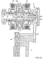
- Fig. 12 is an inside view of the right crankcase cover 17, showing a condition where a clutch actuator accommodating case 99 is covered with a cover member 97 according to a second embodiment of the present invention.
- the accommodating case 99 is not provided with such an upper-portion gap as provided in the first embodiment. Instead, the accommodating case 99 is provided with oil return holes 98 at positions on the upper side of the upper-side actuator 74A, whereby surplus oil is discharged to the inside of the crankcase 2.
- Fig. 13 is a sectional view showing a condition where the cover member 97 according to the second embodiment is mounted to the clutch actuator accommodating case 99. The surplus oil is discharged through the oil return holes 98.
- crankshaft 8 is rotatably borne on the bearings at the mating surfaces of the upper crankcase 2A and the lower crankcase 2B of the crankcase bisected to the upper and lower components, while the main shaft 9 and the counter shaft 10 of the transmission are also rotatably borne on the same mating surfaces, and the crankshaft 8, the main shaft 9 and the counter shaft 10 are arranged substantially at the same height and on the rear side in this order.
- the clutch actuator 74 disposed in the oil sump part 79 formed in the inner surface of the right crankcase cover 17 is located on the upper side of the crankshaft 8 in side view of the internal combustion engine shown in Fig. 1 .
- a parallel 2-cylinder internal combustion engine 100 according to a third embodiment shown in Figures. 14 to 17 has a configuration wherein a crankshaft 108 and a counter shaft 110 are rotatably borne on bearings at mating surfaces of an upper crankcase 102A and a lower crankcase 102B of a crankcase bisected into the upper and lower components, but a main shaft 109 is disposed, between the crankshaft 108 and the counter shaft 110, above the mating surfaces.
- a clutch actuator 122 disposed in an oil sump part 121 formed in an inner surface of a right crankcase cover 120 is located on the lower side of the crankshaft 108 in side view of the internal combustion engine shown in Fig. 14 .
- a twin clutch 112 is provided at a right end portion of the main shaft 109, and the cutch 112 is covered by the right crankcase cover 120 on the right side thereof, so that the right crankcase cover 120 is bulging to the right side at its portion corresponding to the clutch 112.
- the right crankcase cover 120 is formed with an oil sump part 121 in which to dispose the clutch actuator 122 on the lower side of the crankshaft 108 in side view of the internal combustion engine, the oil sump part 121 being so formed as to bulge to the right side.
- the portion corresponding to the clutch 112 which is disposed on the rear upper side of the crankshaft 108 in side view of the internal combustion engine and the oil sump part 121 for the clutch actuator 122 which is disposed on the lower side of the crankshaft 108 are bulging to the right side.
- a recessed space S is formed on the rear side of the clutch actuator 122 with respect to the right crankcase cover 120 and on the lower side of the clutch 112, and the space S can be used as a foot rest space for the rider.
- an upper wall of the upper crankcase 102A forms a slant surface 102s which is facing to a front upper side in positional relationship between the crankshaft 108 and the main shaft 109 located on a rear upper side of the crankshaft 108, and a cylinder block 103, a cylinder head 104, and a cylinder head cover 105 are projected in a forwardly slanted posture from a front portion of the slant surface 102s.
- An engine hanger 115 is projected upward from a rear portion of the slant surface 102s between the crankshaft 108 and the main shaft 109.
- engine hangers 116 and 117 are projected rearwards also from rear walls of the upper crankcase 102A and the lower crankcase 102B.
- a body frame 132 includes a head pipe 133, main frames 134 extending skewly rearwards from the head pipe 133, center frames 135 extending downwards from the rear ends of the main frames 134, a down frame 136 extending downwards from the head pipe 133, seat stays 137 extending rearwards from upper portions of the center frames 135, and mid frames 138 bridgingly arranged between rear portions of the center frames 135 and rear portions of the seat stays 137.
- a front fork 140 for supporting a front wheel 139 is steerably supported on the head pipe 133, and a steering handlebar 141 is connected to an upper portion of the front fork 140.
- a rear fork 143 for supporting a rear wheel 142 is vertically swingably supported through a pivot bolt 145 of the center frame 135.
- a fuel tank 146 is mounted between the left and right main frames 134, and a tandem type seat 147 on which the driver P and a pillion passenger can be seated is mounted onto the left and right seat stays 137 on the rear side of the fuel tank 146.
- the internal combustion engine 100 is disposed in a space surrounded by the main frames 134, the center frames 135 and the down frame 136, on the lower side of the fuel tank 146.
- an engine hanger 115 projected from the slant surface 102s of the upper wall of the upper crankcase 102A of the internal combustion engine 100 is suspended from the main frames 134 through brackets 134b, and the engine hangers 116 and 117 projecting from the rear walls of the upper crankcase 102A and the lower crankcase 102B are supported by the center frames 135, whereby the internal combustion engine 100 is suspended from the vehicle frame 132.
- a step holder 150 is provided at a lower portion of the center frame 135 connected to the mid frame 138, and a foot step 151 is projectingly provided on the step holders 150.
- a foot step 151 is provided at a position in left-right symmetry with the above (see Fig. 17 ).
- the portion corresponding to the clutch 112 and the oil sump part 121 for the clutch actuator 122 are bulging to the right side, and the foot Pf of the driver P is placed in the recessed space S on the lower side of the bulging portion corresponding to the clutch 112 and on the rear side of the oil sump part 121. This ensures that, as shown in Fig. 17 , the feet Pf of the driver P can be settled in optimum positions, without letting the feet Pf of the driver P protrude excessively to the left and right outer sides.
Landscapes
- Engineering & Computer Science (AREA)
- General Engineering & Computer Science (AREA)
- Mechanical Engineering (AREA)
- Physics & Mathematics (AREA)
- Fluid Mechanics (AREA)
- Hydraulic Clutches, Magnetic Clutches, Fluid Clutches, And Fluid Joints (AREA)
- General Details Of Gearings (AREA)
- Lubrication Of Internal Combustion Engines (AREA)
- Control Of Transmission Device (AREA)
Abstract
Description
- The present invention relates to a clutch actuator for actuating a hydraulic clutch of an internal combustion engine.
- Conventionally, there has been an exemplary structure in which a clutch actuator is mounted to the outside of a crankcase of an internal combustion engine. In this structure, however, during the operation of the clutch actuator, the operating sounds generated at valve opening and closing times are transmitted to the exterior, which naturally is undesirable (see, for example, Japanese Patent Laid-open No.
2008-057620 Figure 3 )). - Besides, there has been another exemplary structure in which a clutch actuator is mounted to the inside of a crankcase. Also in this structure, however, sounds are echoed onto a thin clutch cover, again leading to leakage of operating sounds to the exterior (see, for example, Japanese Laid-open No.
2008-138541 Figure 6 )). - It is an object of the present invention to ensure that the operating sounds generated at the time of operation of a clutch actuator for actuating a hydraulic clutch of an internal combustion engine are prevented from being transmitted to the exterior.
- The present invention has been made to solve the above-mentioned problem.
- The invention according to claim 1 pertains to a clutch actuator structure including, provided for an internal combustion engine, a hydraulic clutch mechanism for transmitting a rotational driving force of a crankshaft by oil pressure and interrupting the transmission, and a clutch actuator for controlling an oil pressure for engaging and disengaging the hydraulic clutch mechanism, characterized in that an oil sump part for reserving the oil is provided in the periphery of the clutch actuator, and the clutch actuator is disposed in the oil sump part.
- The invention according to
claim 2 is characterized, in the clutch actuator structure according to claim 1, in that the clutch actuator is mounted to the inside of the oil sump part provided in a crankcase or a crankcase cover, and a cover member is fixed so as to cover the oil sump part. - The invention according to
claim 3 is characterized, in the clutch actuator structure according to any ofclaims 1 and 2, in that the clutch mechanism includes a plurality of clutches, and a plurality of oil passages are formed to extend from the clutch actuator to the clutch mechanism substantially in parallel to each other. - The invention according to claim 4 is characterized, in the clutch actuator structure according to any of claims 1 to 3, in that an oil discharge hole provided in the clutch actuator opens into the oil sump part.
- The invention according to claim 5 is characterized in the clutch actuator structure according to claim 4, in that the clutch actuator includes a tubular member to which the plurality of oil passages are connected, and
a sliding member operating in the tubular member so as to switch over communicating conditions of the oil passages; and
the tubular member and the sliding member are made to slide by an operation of the clutch actuator,
whereby a return oil from a clutch is discharged from the discharge hole. - The invention according to
claim 6 is characterized, in the clutch actuator structure according to claim 5, in that a supply oil passage for supplying the oil from an oil pump to a valve part including the tubular member and the sliding member is branched and extended to form a clutch lubricating oil passage. - The invention according to
claim 7 is characterized, in the clutch actuator structure according toclaim 2, in that the cover member is formed therein with an oil return hole above the clutch actuator. - The invention according to claim 8 is characterized, in the clutch actuator structure according to claim 1, in that the clutch actuator is located on a front lower side of the clutch mechanism in side view of the internal combustion engine, and is disposed on the inside of the oil sump part provided in the crankcase cover.
- The invention according to
claim 9 is characterized, in the clutch actuator structure according to claim 8, in that the clutch mechanism is disposed on a rear upper side of the crankshaft in side view of the internal combustion engine, and the clutch actuator is disposed on the lower side of the crankshaft in side view of the internal combustion engine. - The invention according to
claim 10 is characterized, in the clutch actuator structure according toclaim 9, in that a main shaft coaxial with the clutch mechanism is disposed on a rear upper side of the crankshaft, an upper wall of the crankcase forms a slant surface facing toward a front upper side between the crankshaft and the main shaft, and an engine hanger is projectingly formed on the slant surface of the upper wall of the crankcase. - In the invention of claim 1, the oil sump part is provided, and the clutch actuator is disposed in the oil sump part. Therefore, the valve opening and closing sounds generated during the operation of the clutch actuator can be attenuated, and the sound leaking to the exterior is reduced.
- In the invention of
claim 2, the oil sump part can be formed in a simple structure. - In the invention of
claim 3, the plurality of oil passages can be formed substantially in parallel to each other. Therefore, notwithstanding the oil passages are provided in plurality, they can be arranged efficiently. In addition, since the directions of machining can be unified, machinability can be enhanced. - In the invention of claim 4, the oil discharged from the clutch actuator is reserved, whereby the effect of claim 1 can be produced. Therefore, the need for other oil supply means is eliminated, and the number of component parts is reduced.
- In the invention of claim 5, the return oil is discharged from the discharge hole by sliding of the sliding member. Therefore, the sliding part can be lubricated utilizing the oil thus discharged.
- In the invention of
claim 6, the supply oil passage is branched and extended to form the clutch lubricating oil passage, which is easier to carry out than the formation of a clutch lubricating oil passage communicating with other lubricating oil circuit. Accordingly, the number of machining steps is reduced. - In the invention of
claim 7, the oil return hole is formed above the clutch actuator by the cover member. Therefore, it is ensured that the clutch actuator is sufficiently immersed in the oil, so that surplus oil can be speedily recovered into the internal combustion engine while producing the operating sound reducing effect. - In the invention of claim 8, the clutch actuator is disposed on the inside of the oil sump part provided in the crankcase cover, so that the clutch actuator projects on a lateral side of the internal combustion engine together with the clutch mechanism. However, since the clutch actuator is located on the front lower side of the clutch mechanism in side view of the internal combustion engine, a foot rest space for the rider can be secured at an optimum position on the rear side of the clutch actuator and on the lower side of the clutch mechanism.
- Incidentally, since the oil sump part to which the clutch actuator is mounted is provided in the crankcase cover, a situation that the space inside the crankcase is limited to be narrower by the oil sump part can be obviated.
- In the invention of
claim 9, the clutch mechanism is disposed on a rear upper side of the crankshaft in side view of the internal combustion engine, and the clutch actuator is disposed on the lower side of the crankshaft in side view of the internal combustion engine. Therefore, a position on the rear lower side of the crankshaft becomes a foot rest position for the rider, and the position is an optimum position as a foot rest position for the rider in the case of a motorcycle in which the internal combustion engine is horizontally mounted on a vehicle body. - In the invention of
claim 10, the main shaft coaxial with the clutch mechanism is disposed on a rear upper side of the crankshaft, the upper wall of the crankcase forms the slant surface facing toward a front upper side between the crankshaft and the main shaft, and the engine hanger is projectingly formed on the slant surface. Therefore, it is unnecessary to provide the engine hanger in the state of projecting upward beyond a highest part of the crankcase, so that the internal combustion engine can be mounted on the vehicle body in a compact fashion. - Further features and advantages of the present invention will become apparent from the following description of non-limiting exemplary embodiments, with reference to the attached drawings.
-
Fig. 1 is a right side view of an internal combustion engine according to an embodiment of the present invention. -
Fig. 2 is a sectional view of a transmission for the internal combustion engine. -
Fig. 3 is an enlarged view of the vicinity of a clutch. -
Fig. 4 is an outside view of a right crankcase cover. -
Fig. 5 is an inside view of the right crankcase cover. -
Fig. 6 is a view showing a condition where a clutch actuator accommodating case is covered with a cover member. -
Fig. 7 illustrates the structure and operation of a clutch actuator. -
Fig. 8 is a sectional view of a supply oil passage for supplying oil to the clutch actuator. -
Fig. 9 is a sectional view of a control oil passage communicating with a pressurization chamber in a first clutch. -
Fig. 10 is a sectional view of a control oil passage communicating with a pressurization chamber in a second clutch. -
Fig. 11 is a sectional view of a lubricating oil passage communicating with a pressure regulation chamber in the first clutch. -
Fig. 12 is a view showing a condition where the clutch actuator accommodating case is covered with a cover member according to a second embodiment of the present invention. -
Fig. 13 is a sectional view showing a condition where the cover member according to the second embodiment is mounted to the clutch actuator accommodating case. -
Fig. 14 is a right side view of an internal combustion engine according to a third embodiment of the invention. -
Fig. 15 is a right side view of a motorcycle on which the internal combustion engine is mounted. -
Fig. 16 is an enlarged view of a major part ofFig. 15 . -
Fig. 17 is a partial front view of the motorcycle. -
Fig. 1 is a right side view of an internal combustion engine 1 according to an embodiment of the present invention. The internal combustion engine 1 is a parallel two-cylinder internal combustion engine. Arrow F indicates the front side corresponding to the front side of a vehicle on which the internal combustion engine 1 is mounted. - A main outer shell of the internal combustion engine 1 includes a
crankcase 2 which is composed of anupper crankcase 2A and alower crankcase 2B, acylinder block 3, a cylinder head 4, a cylinder head cover 5, and anoil pan 6. Atransmission 7 is integrally incorporated in thecrankcase 2. - A crankshaft 8, and a
main shaft 9 and acounter shaft 10 of the transmission are rotatably borne on bearings at mating surfaces of thecrankcase 2 which is bisected to the upper and lower components. - The
oil pan 6 connected to the lower end of thelower crankcase 2B is provided with anoil suction pipe 12 having astrainer 11, and acontrol oil pump 13 and acontrol oil filter 14 connected thereto are connected to an upper portion of theoil suction pipe 12. - The internal combustion engine 1 is provided also with a lubricating oil pump, which is omitted in the drawing.
- A lubricating
oil filter 15 is shown in the figure. The discharge pressure of thecontrol oil pump 13 is set high for clutch actuator use, and the discharge pressure of the lubricating oil pump is lower than the discharge pressure of the control oil pump. - The
transmission 7 accommodated in a rear portion of thecrankcase 2 of the internal combustion engine 1 is a constant-mesh type twin-clutch transmission. - In addition, a change mechanism including a
shift drum 16 and the like for changing the transmission gear speed is accommodated in the rear portion of thecrankcase 2. - A crankcase right side portion is covered with a
right crankcase cover 17. Outside portions of various oil passages are bulging in the form of folds on the outer surface of theright crankcase cover 17. - Incidentally, an
output shaft 18 for driving the vehicle by obtaining power from thecounter shaft 10 is provided below the crankshaft 8. -
Fig. 2 is a sectional view of thetransmission 7. - The change mechanism including the shift drum and a shift fork is omitted in the drawing.
- Arrows L and R indicate leftward and rightward directions corresponding to the left and right sides of the vehicle on which the internal combustion engine 1 is mounted.
- The
transmission 7 includes themain shaft 9, thecounter shaft 10, a primary drivengear 20, and a pair ofclutches 21 consisting of a first clutch 21A and a second clutch 21B. - Of the
main shaft 9, the left end is rotatably borne on thecrankcase 2 through aball bearing 22, and a central portion on thecrankcase 2 through a ball bearing 23. - The right end of the
main shaft 9 is rotatably borne on theright crankcase cover 17 through aball bearing 24. - Of the counter shaft, the left end is rotatably borne on the
crankcase 2 through aball bearing 25, and the right end on thecrankcase 2 through aneedle bearing 26. - The
main shaft 9 includes a long main shaftinner shaft 9A, a main shaftouter shaft 9B, and a clutch part outer shaft 9C. - The main shaft
outer shaft 9B covers a part of the main shaftinner shaft 9A in a relatively rotatable manner, with aneedle bearing 27 therebetween. - The left end of the main shaft
outer shaft 9B is restrained by a C-shapedsnap ring 28 from leftward movement. - The right end of the main shaft
outer shaft 9B abuts on the clutch part outer shaft 9C, with anannular spacer 29 therebetween, and is restrained from rightward movement. Six gears M1 to M6 are provided on themain shaft 9, while six gears C1 to C6 constantly meshing with these gears M1 to M6 are provided on thecounter shaft 10, correspondingly to the gears M1 to M6. - Here, M indicates that the gear belongs to the main shaft, while C indicates that the gear belongs to the counter shaft, and suffixes 1 to 6 indicate that the gears are for determining the first-speed to sixth-speed gear ratios, respectively.
- The odd-numbered speed gears M1, M5 and M3 are provided on the main shaft
inner shaft 9A, while the even-numbered speed gears M4, M6 and M2 are provided on the main shaftouter shaft 9B. - In
Fig. 2 , suffix x attached to the gear symbol indicates a fixed gear which is formed integrally with a shaft, suffix w indicates an idle gear which is held on a shaft and which can be rotated relative to the shaft at a predetermined position on the shaft, and suffix s indicates a slide gear which is slidable in the axial direction. - The slide gear is held on the shaft by
splines 30 so that it is incapable of relative rotation to the shaft in the circumferential direction but is capable of sliding in the axial direction. - A gear meshed with the fixed gear (suffix x) or the slide gear (suffix s) is necessarily an idle gear (suffix w).
- The idle gear (suffix w) cannot function as a gear by itself. For the idle gear (suffix w) to function as a gear, it must be fixed to the shaft by the slide gear (suffix s) provided adjacent thereto.
- The slide gear is provided with an engaging groove G for engagement with the shift fork of the change mechanism (not shown). The slide gear (suffix s) is moved in the axial direction by the shift fork engaged therewith.
-
Fig. 3 is an enlarged view of the vicinity of theclutches 21. - The clutch part outer shaft 9C is provided on a right half of the main shaft
inner shaft 9A. - The clutch part outer shaft 9C covers the peripheries of end portions of the main shaft
inner shaft 9A in a rotatable manner, withneedle bearings - The right end of the clutch part outer shaft 9C abuts on other member, with an
annular spacer 32 therebetween, and is restrained together with the member from movement, by awasher 33 and a nut 34 provided at an end of the main shaftinner shaft 9A. - The left end of the clutch part outer shaft 9C abuts on the right end of the main shaft
outer shaft 9B, with theannular spacer 29 therebetween. The left end of the main shaftouter shaft 9B is restrained by the C-shapedsnap ring 28 from movement (Fig. 2 ). - The primary driven
gear 20 andclutch outers splines 38 and C-shaped snap rings 39, respectively. - The primary driven
gear 20 is non-rotatably fitted to the clutch part outer shaft throughsplines 19. - Movements of the primary driven
gear 20 in the left-right direction are restrained by theclutch outers - The primary driven
gear 20 is a gear in constant mesh with a primary drive gear (not shown) provided on the crankshaft 8, and, by receiving a rotational driving force from the crankshaft 8, drives the clutch part outer shaft 9C to rotate. - According to this, the
clutch outers clutches 21 are rotated together. -
Clutch inners clutches 21 are connected respectively to separate members. - The clutch inner 40A of the first clutch 21A is fitted to
splines 41 at the right end of the main shaftinner shaft 9A, and is fixed to the main shaftinner shaft 9A by thewasher 33 and the nut 34. - The clutch inner of the second clutch 21B is fixed by being fitted to
splines 42 at the right end of the main shaftouter shaft 9B. - The pair of
clutches - On the inside of an outer circumferential portion of each of the
clutch outers clutches 21, a plurality ofdrive friction discs 43 are provided which are engaged with the clutch outer 37 so as to be incapable of relative rotation but capable of axial movement. - On the outside of each of the clutch inners 40 of the pair of
clutches 21, a plurality of drivenfriction discs 44 are provided which are engaged with the clutch inner 40 so as to be incapable of relative rotation but capable of axial movement. - The
drive friction discs 43 and the drivenfriction discs 44 are alternately disposed to constitute afriction disc group 45. - A
pressure plate 46 is provided between anend plate part 37x of the clutch outer 37A, 37B and thefriction disc group 45 in each of theclutches 21. An end portion of an outer circumferential portion of thepressure plate 46 abuts on thedrive friction disc 43 at one end of thefriction disc group 45. - The
drive friction disc 43 at the other end of thefriction disc group 45 is restrained by a C-shapedsnap ring 47 from movement. - A
spring bearing member 48 is provided between thepressure plate 46 and the clutch inner 40. - The inner circumferential end of the
spring bearing member 48 is restrained from movement, by a C-shapedsnap ring 49 provided on a clutchouter boss part 37y. - The outer circumferential end of the
spring bearing member 48 is in sliding contact with the inside of an outer circumferential portion of thepressure plate 46, with aseal member 50 therebetween. - The
pressure plate 46 is pressed toward the clutch outerend plate part 37x, by acoil spring 51 abutting on thespring bearing member 48 at its one end. - A pressurization chamber 52 (52A, 52B) is formed between the clutch outer
end plate part 37x and thepressure plate 46. - A pressure regulation chamber 53 (53A, 53B) is formed between the
spring bearing member 48 and thepressure plate 46. - The pressure regulation chamber 53 is a chamber such that a pressure increase in the pressure chamber 52 by a centrifugal force is canceled by a pressure increase due to a centrifugal force exerted on the oil in the pressure regulation chamber 53, whereby the clutch is disengaged.
- The main shaft
inner shaft 9A is provided with a main shaft left-side center hole 56 opening to the left side, and a main shaft right-side center hole 57 opening to the right side. - The right-
side center hole 57 is a stepped hole having a plurality of stages of inside diameter. - Two coaxial pipes, namely, an
inner pipe 58 and anouter pipe 59 are inserted in the right-side center hole 57. - A left end portion of the
inner pipe 58 is fitted in the small-diameter portion of the right-side center hole 57, with aseal member 60A therebetween. A right end portion of theinner pipe 58 is supported on theright crankcase 17, with aseal member 60B therebetween. The inside of theinner pipe 58 and the outside of theinner pipe 58 are partitioned from each other through theseal members - A left end portion of the
outer pipe 59 is fitted in the large-diameter portion of the right-side center hole 57, with aseal member 61A therebetween. Aright end portion of theouter pipe 59 is supported on theright crankcase 17, with aseal member 61B therebetween. The inside of theouter pipe 59 and the outside of theouter pipe 59 are partitioned from each other by theseal members - An oil passage formed between the outside of the
inner pipe 58 and the inside of theouter pipe 59 and the inside of the middle-diameter portion of the right-side center hole 57 is referred to as main shaft endfirst oil passage 62A; an oil passage connecting the inner bore of theinner pipe 58 with the small-diameter portion of the right-side center hole 57 is referred to as main shaft endsecond oil passage 62B; and an oil passage formed between the outside of theouter pipe 59 and the inside of the large-diameter portion of the right-side center hole 57 is referred to as main shaft end third oil passage 62C. - The main shaft end
first oil passage 62A communicates with thepressurization chamber 52A of the first clutch 21A throughoil passages 63 which radially penetrate the main shaftinner shaft 9A and the clutch part outer shaft 9C for the communication. - The main shaft end
second oil passage 62B communicates with thepressurization chamber 52B of the second clutch 21B throughoil passages 64 which radially penetrate the main shaftinner shaft 9A and the clutch part outer shaft 9C for the communication. - The main shaft end third oil passage 62C communicates with the
pressure regulation chamber 53A of the first clutch 21A through anoil passage 65 which radially penetrates the main shaftinner shaft 9A, theneedle bearing 31A, a main shaft inner shaft outer circumferentialgap oil passage 66, and anoil passage 67 which radially penetrates the clutch part outer shaft 9C. - Incidentally, the main shaft left-
side center hole 56 communicates with thepressure regulation chamber 53B of the second clutch 21B through anoil passage 68 which radially penetrates the main shaftinner shaft 9A, theneedle bearing 31B, a main shaft inner shaft outer circumferentialgap oil passage 69, and anoil passage 70 which radially penetrates the clutch part outer shaft 9C. -
Fig. 4 is an outside view of theright crankcase cover 17. - A pair of
clutch actuators 74, namely, an upper-sideclutch actuator 74A and a lower-sideclutch actuator 74B are accommodated in the clutchactuator accommodating case 73 provided at the inside surface of theright crankcase cover 17. - Pipe parts are bulging in the form of folds on the outside surface of the
right crankcase cover 17. A singlesupply oil passage 75 which extends from thecontrol oil pump 13 toward theclutch actuators 74 through thecontrol oil filter 14, and controloil passages lubricating oil passage 77 which extend from theclutch actuators 74 toward theclutches 21, are provided in the pipe parts. - The
control oil passage 76A extending from the upper-sideclutch actuator 74A reaches the main shaft endfirst oil passage 62A inFig. 3 . A control oil is fed from the upper-sideclutch actuator 74A to thepressurization chamber 52A of the first clutch 21A. - The
control oil passage 76B extending from the lower-sideclutch actuator 74B reaches the main shaft endsecond oil passage 62B. The control oil is fed from the lower-sideclutch actuator 74B to thepressurization chamber 52B of the second clutch 21B. - The lubricating
oil passage 77 branched and extended from thesupply oil passage 75 through a communicatingoil passage 80 reaches the main shaft end third oil passage 62C. The control oil is constantly fed from thesupply oil passage 75 to thepressure regulation chamber 53A of the first clutch 21A, as a lubricating oil. - Incidentally, the
pressure regulation chamber 53B of the second clutch 21B is fed with the lubricating oil from the main shaft left-side center hole 56 communicating with the lubricating oil pump. - In each of the oil passages mentioned above, the oil reciprocates according to engagement and disengagement of the relevant clutch.
- It should be noted here, however, that the oil in the supply oil passage and the lubricating oil in the main shaft left-
side center hole 56 do not reciprocate. -
Fig. 5 is an inside view of theright crankcase cover 17. The lubricatingoil passage 77 communicates with thesupply oil passage 75 through the communicatingoil passage 80. The clutchactuator accommodating case 73 in which theclutch actuators 74 are accommodated is covered with acover member 78 shown inFig. 6 . -
Fig. 6 is an inside view of theright crankcase cover 17, showing a condition where the clutchactuator accommodating case 73 is covered with thecover member 78. - The inside of this member functions as an
oil sump part 79, and the return oil from theclutches 21 is discharged into theoil sump part 79. - A
gap 95 is provided at an upper portion of the clutchactuator accommodating case 73, so that surplus oil is discharged through thegap 95 into the inside of thecrankcase 2. -
Fig. 7 illustrates the structure and operation of theclutch actuator 74. - Two
clutch actuators 74 having this configuration are provided, as above-mentioned. - In
Fig. 7 , theclutch actuator 74 includes: amagnet coil 83 accommodated in asolenoid case 82; aniron piece 84 receiving an electromagnetic force of themagnet coil 83; avalve case 85; avalve element 86 accommodated in thevalve case 85; a connectingrod 87 for connecting theiron piece 84 with thevalve element 86; areturn spring 88; and a spring bearing cover 89 for bearing the outer end of thereturn spring 88. - The
iron piece 84 and the connectingrod 87 and thevalve element 86 are moved rectilinearly in thevalve case 85, as one body. Thevalve case 85 is provided therein with thesupply oil passage 75, thecontrol oil passage 76, the lubricating oil passage 77 (Fig. 11 ), the communicating oil passage 80 (Fig. 11 ), a pressureregulation oil passage 90 which is branched from the control oil passage to reach an end portion of the valve element, and a return oildischarge oil passage 91. -
Fig. 7(a) shows the position of thevalve element 86 when theclutch actuator 74 is OFF. - In
Fig. 7 , the densely crosshatched parts H indicate a high-pressure oil, while coarsely crosshatched parts L indicate a low-pressure oil. An end portion on the valve side of thesupply oil passage 75 supplied with the high-pressure oil from theoil pump 13 is shut off by thevalve element 86, whereby the oil is stopped. -
Fig. 7(b) shows the position of thevalve element 86 at the moment themagnet coil 83 is energized to turn ON theclutch actuator 74. - The
valve element 86 has been moved to the right end of an ironpiece moving space 92 in the figure, against the biasing force of thereturn spring 88. There is shown a condition where thesupply oil passage 75 and space at a small-diameter portion 86a of thevalve element 86 communicate with each other, the high-pressure oil has started flowing into thecontrol oil passage 76, and the oil pressure is rising. -
Fig. 7(c) shows a condition where the pressure rise is completed. - The pressure in the pressure
regulation oil passage 90 branched from thecontrol oil passage 76 has also been raised, and the high pressure in the pressureregulation oil passage 90 acts on the end portion side of thevalve element 86, so that thevalve element 86 is a little pushed back. - As a result, a valve-side end portion of the
supply oil passage 75 is shut off by thevalve element 86, so that the supply of the high-pressure oil into thecontrol oil passage 76 is stopped. In addition, since an actuator-side end portion of thecontrol oil passage 76 is also shut off, the inside of the pressurization chamber 52 (Fig. 3 ) of the clutch 21 is maintained at a high pressure, the pressure plate is pushed, and themultiple disc clutch 21 is put into an engaged state. - When an instruction to turn OFF the
clutch actuator 74 is given, the energizing of themagnet coil 83 is stopped, so that the electromagnetic force for pushing thevalve element 86 is lost, and thevalve element 86 is returned to the position inFig. 7(a) by the biasing force of thereturn spring 88. - As a result, the
control oil passage 76 communicates with the return oildischarge oil passage 91, and the oil is returned from the clutch 21 by the action of thecoil spring 51 in the pressure regulation chamber 53 of the clutch 21, to be discharged from the return oildischarge oil passage 91. Consequently, themultiple disc clutch 21 is disengaged. - The oil thus discharged collects in the
oil sump part 79 in the clutchactuator accommodating case 73. - The
clutch actuators 74 are immersed in this oil. - The oil flows through the gap at the
spring bearing cover 89 into the gap between thevalve case 85 and thevalve element 86, to lubricate the sliding surfaces. Besides, since theclutch actuators 74 are immersed in the oil, the operating sounds generated from theclutch actuators 74 are intercepted, and transmission of the sounds to the exterior is suppressed. -
Fig. 8 is a sectional view of thesupply oil passage 75 for supplying the oil from thecontrol oil pump 13 to theclutch actuators 74 through thecontrol oil filter 14. - The
supply oil passage 75 is formed in a wall body of theright crankcase cover 17. - Two
clutch actuators 74 are accommodated, at upper and lower positions, in the clutchactuator accommodating case 73. - The oil is supplied into an intermediate area between the
clutch actuators 74, to be supplied respectively to the upper-sideclutch actuator 74A and the lower-sideclutch actuator 74B. - A
gap 95 is provided at an upper joint portion between the clutchactuator accommodating case 73 and thecover member 78 for covering an opening of the clutchactuator accommodating case 73. Therefore, surplus oil is discharged into the inside of thecrankcase 2. -
Fig. 9 is a sectional view of thecontrol oil passage 76A extending from the upper-sideclutch actuator 74A to thepressurization chamber 52A of the first clutch 21A. - This oil passage extends through a right crankcase cover inside
space 93A and the main shaft endfirst oil passage 62A, and through theoil passages 63, to reach thepressurization chamber 52A of the first clutch 21A. - When the high-pressure oil is supplied into the
pressurization chamber 52A of the first clutch 21A, thepressure plate 46 is moved toward thefriction disc group 45 against the biasing force of thecoil spring 51. As a result, the friction discs are pressed against one another, so that the rotation of the clutch outer 37A is transmitted to the clutch inner 40A, and the main shaftinner shaft 9A is driven to rotate. -
Fig. 10 is a sectional view of thecontrol oil passage 76B extending from the lower-sideclutch actuator 74B to thepressurization chamber 52B of the second clutch 21B. - This oil passage extends through a right crankcase cover inside
space 93B and the main shaft endsecond oil passage 62B, and through theoil passages 64, to reach thepressurization chamber 52B of the second clutch 21B. - When the high-pressure oil is supplied into the
pressurization chamber 52B of the second clutch 21B, thepressure plate 46 is moved toward thefriction disc group 45 against the biasing force of thecoil spring 51. Consequently, the friction discs are pressed against one another, so that the rotation of the clutch outer 37B is transmitted to the clutch inner 40B, and the main shaftouter shaft 9B is driven to rotate. -
Fig. 11 is a sectional view of the lubricatingoil passage 77 extending from the lower-sideclutch actuator 74B to thepressure regulation chamber 53A of the first clutch 21A. - This oil passage includes the communicating
oil passage 80 which is formed, between thevalve case 85 and aplate 94 in the lower-sideclutch actuator 74B, so as to make thesupply passage 75 and the lubricatingoil passage 77 communicate with each other. The high-pressure oil supplied through thesupply oil passage 75 is constantly supplied to the lubricatingoil passage 77 through the communicatingoil passage 80. - The
plate 94 is provided with anorifice 81, to contrive a lowering in the pressure of the oil supplied into the lubricatingoil passage 77. - The lubricating
oil passage 77 extends through a right crankcase cover inside space 93C and the main shaft end third oil passage 62C, then through theoil passage 65, theneedle bearing 31A, and theoil passages pressure regulation chamber 53A of the first clutch 21A. The high-pressure oil is supplied through the lubricatingoil passage 77 into thepressure regulation chamber 53A. - The oil thus supplied lubricates the
needle bearing 31A. - Incidentally, the pressure regulation chamber 53 of the second clutch 21B is supplied with a low-pressure lubricating oil from the main shaft left-
side center hole 56 through theoil passage 68, theneedle bearing 31B, and theoil passages - The pair of clutch actuators are so operated that when one of them is ON, the other of them is OFF.
- Which one of the pair of clutch actuators is to be turned ON is automatically decided by an electronic control unit (not shown).
- At the time of starting the engine, the clutch actuator operation is carried out in order to confirm the operating conditions of the clutch actuators. The oil discharged in this operation can be reserved in the
oil sump part 79. - Therefore, even in the case where the vehicle has been left non-operated for a long time, the condition where the oil is reserved in the
oil sump part 79 is attained at the time of operating the engine. This contributes to prevention of leakage of operating sounds and to lubrication. - While the embodiment of the present invention has been described presuming its application to a clutch mechanism, the technology of preventing leakage of actuator operating sounds can also be applied to other oil pressure control mechanisms.
- Besides, while the clutch actuators are of the horizontal type in the embodiment above, they may be of the vertical type. The clutch actuators may be disposed not only in the right crankcase cover but also in any other parts in the crankcase.
-
Fig. 12 is an inside view of theright crankcase cover 17, showing a condition where a clutchactuator accommodating case 99 is covered with acover member 97 according to a second embodiment of the present invention. - The
accommodating case 99 is not provided with such an upper-portion gap as provided in the first embodiment. Instead, theaccommodating case 99 is provided with oil return holes 98 at positions on the upper side of the upper-side actuator 74A, whereby surplus oil is discharged to the inside of thecrankcase 2. -
Fig. 13 is a sectional view showing a condition where thecover member 97 according to the second embodiment is mounted to the clutchactuator accommodating case 99. The surplus oil is discharged through the oil return holes 98. - In the internal combustion engines 1 in the first and second embodiments described above, the crankshaft 8 is rotatably borne on the bearings at the mating surfaces of the
upper crankcase 2A and thelower crankcase 2B of the crankcase bisected to the upper and lower components, while themain shaft 9 and thecounter shaft 10 of the transmission are also rotatably borne on the same mating surfaces, and the crankshaft 8, themain shaft 9 and thecounter shaft 10 are arranged substantially at the same height and on the rear side in this order. - In addition, the
clutch actuator 74 disposed in theoil sump part 79 formed in the inner surface of theright crankcase cover 17 is located on the upper side of the crankshaft 8 in side view of the internal combustion engine shown inFig. 1 . - In contrast to the first and second embodiments, a parallel 2-cylinder
internal combustion engine 100 according to a third embodiment shown inFigures. 14 to 17 has a configuration wherein acrankshaft 108 and acounter shaft 110 are rotatably borne on bearings at mating surfaces of anupper crankcase 102A and alower crankcase 102B of a crankcase bisected into the upper and lower components, but amain shaft 109 is disposed, between thecrankshaft 108 and thecounter shaft 110, above the mating surfaces. - Besides, a
clutch actuator 122 disposed in anoil sump part 121 formed in an inner surface of aright crankcase cover 120 is located on the lower side of thecrankshaft 108 in side view of the internal combustion engine shown inFig. 14 . - A
twin clutch 112 is provided at a right end portion of themain shaft 109, and thecutch 112 is covered by theright crankcase cover 120 on the right side thereof, so that theright crankcase cover 120 is bulging to the right side at its portion corresponding to the clutch 112. - The
right crankcase cover 120 is formed with anoil sump part 121 in which to dispose theclutch actuator 122 on the lower side of thecrankshaft 108 in side view of the internal combustion engine, theoil sump part 121 being so formed as to bulge to the right side. - Thus, of the
right crankcase cover 120, the portion corresponding to the clutch 112 which is disposed on the rear upper side of thecrankshaft 108 in side view of the internal combustion engine and theoil sump part 121 for theclutch actuator 122 which is disposed on the lower side of thecrankshaft 108 are bulging to the right side. - Therefore, a recessed space S is formed on the rear side of the
clutch actuator 122 with respect to theright crankcase cover 120 and on the lower side of the clutch 112, and the space S can be used as a foot rest space for the rider. - In this
internal combustion engine 100, an upper wall of theupper crankcase 102A forms aslant surface 102s which is facing to a front upper side in positional relationship between thecrankshaft 108 and themain shaft 109 located on a rear upper side of thecrankshaft 108, and acylinder block 103, acylinder head 104, and acylinder head cover 105 are projected in a forwardly slanted posture from a front portion of theslant surface 102s. - An
engine hanger 115 is projected upward from a rear portion of theslant surface 102s between thecrankshaft 108 and themain shaft 109. - In addition,
engine hangers upper crankcase 102A and thelower crankcase 102B. - In a
motorcycle 130 on which thisinternal combustion engine 100 is mounted, as shown inFig. 15 , abody frame 132 includes ahead pipe 133,main frames 134 extending skewly rearwards from thehead pipe 133, center frames 135 extending downwards from the rear ends of themain frames 134, adown frame 136 extending downwards from thehead pipe 133, seat stays 137 extending rearwards from upper portions of the center frames 135, andmid frames 138 bridgingly arranged between rear portions of the center frames 135 and rear portions of the seat stays 137. - A
front fork 140 for supporting afront wheel 139 is steerably supported on thehead pipe 133, and asteering handlebar 141 is connected to an upper portion of thefront fork 140. - In addition, a
rear fork 143 for supporting arear wheel 142 is vertically swingably supported through apivot bolt 145 of thecenter frame 135. - A
fuel tank 146 is mounted between the left and rightmain frames 134, and atandem type seat 147 on which the driver P and a pillion passenger can be seated is mounted onto the left and right seat stays 137 on the rear side of thefuel tank 146. - The
internal combustion engine 100 is disposed in a space surrounded by themain frames 134, the center frames 135 and thedown frame 136, on the lower side of thefuel tank 146. - As shown in
Fig. 16 , anengine hanger 115 projected from theslant surface 102s of the upper wall of theupper crankcase 102A of theinternal combustion engine 100 is suspended from themain frames 134 through brackets 134b, and theengine hangers upper crankcase 102A and thelower crankcase 102B are supported by the center frames 135, whereby theinternal combustion engine 100 is suspended from thevehicle frame 132. - As shown in
Fig. 15 , on the right side of the vehicle body, astep holder 150 is provided at a lower portion of thecenter frame 135 connected to themid frame 138, and afoot step 151 is projectingly provided on thestep holders 150. - On the left side of the vehicle body, similarly, a
foot step 151 is provided at a position in left-right symmetry with the above (seeFig. 17 ). - When the driver P is seated on the
tandem type seat 147 and put his or her feet Pf on the foot steps 151, as shown inFigures 15 and16 , the toe of the foot Pf is accommodated in the recessed space S on the rear side of theclutch actuator 122 at a position on the rear lower side of the crankshaft, namely, on the lower side of the clutch 112. - Of the
right crankcase cover 120 covering the right side of thecrankcases internal combustion engine 100, the portion corresponding to the clutch 112 and theoil sump part 121 for theclutch actuator 122 are bulging to the right side, and the foot Pf of the driver P is placed in the recessed space S on the lower side of the bulging portion corresponding to the clutch 112 and on the rear side of theoil sump part 121. This ensures that, as shown inFig. 17 , the feet Pf of the driver P can be settled in optimum positions, without letting the feet Pf of the driver P protrude excessively to the left and right outer sides. - As has been described in detail above, in the above-mentioned embodiments, the following effects are obtained.
- (1) In
Figures 5 ,6 and8 , theoil sump part 79 for reserving oil is provided in the periphery of theclutch actuators 74, and theclutch actuators 74 are disposed in the oil sump part 79 (seeFigures 5 ,6 and8 ). Therefore, the valve opening and closing sounds generated during operation of theclutch actuators 74 can be attenuated, and the sound leaking to the exterior can be reduced. - (2) Since the
clutch actuators 74 are mounted to the inside of theoil sump part 79 provided in thecrankcase cover 17 and the cover member 78 (seeFig. 6 ) is so fixed as to cover theoil sump part 79, theoil sump part 79 can be formed in a simple structure. - (3) Since the clutch mechanism is composed of the pair of
clutches Fig. 3 ) and the threeoil passages clutch actuators 74 to the clutch mechanism substantially in parallel to each other (seeFig. 4 ), the oil passages provided in plurality can be arranged efficiently. In addition, since the directions of machining are unified, machinability can be enhanced. - (4) Since the oil
discharge oil passage 91 provided in theclutch actuator 74 is opening into theoil sump part 79, it is possible to reserve the oil discharged from theclutch actuator 74 and thereby to produce the effect of (1) above. Accordingly, the need for other oil supply means is eliminated, and the number of component parts can be reduced. - (5) The
clutch actuator 74 includes thetubular valve case 85 to which a plurality of oil passages are connected, and thevalve element 86 slid in thevalve case 85 so as to switch over the communicating conditions of the oil passages (seeFig 7 ), and thevalve element 86 is slid in thevalve case 85 by an operation of theclutch actuator 74, whereby the return oil from the clutch is discharged via thedischarge oil passage 91. Therefore, the sliding parts can be lubricated utilizing the oil thus discharged. - (6) The
supply oil passage 75 for supplying the oil from theoil pump 13 to the valve part including thevalve case 85 and thevalve element 86 is branched and extended to form the clutchlubricating oil passage 77 and the communicating oil passage 80 (seeFigures 5 and11 ). Thus, the clutchlubricating oil passage 77 is formed by branching and extending thesupply oil passage 75, which is easier to carry out than the formation of a clutch lubricating oil passage communicating with other lubricating oil circuit. Consequently, the number of machining steps is reduced. - (7) Since only a single
supply oil passage 75 is provided for supplying the oil to the pair ofactuators - (8) Design quality is enhanced, as compared with the case (prior art) in which the
clutch actuators - (9) Since the clutch actuators are also cooled by the oil in the
oil sump part 79 which is cooled through the wall body of thecrankcase cover 17, cooling performance is enhanced. - (10) Since the clutch 112 is disposed on the rear upper side of the
crankshaft 108 in side view of the internal combustion engine and theclutch actuator 122 is disposed on the lower side of thecrankshaft 108 in side view of the internal combustion engine (seeFig. 16 ), the recessed space S on the lower side of the clutch 112 and on the rear side of theclutch actuator 122 can be secured as an optimum foot rest position for the driver. - (11) Since the
engine hanger 115 is projectingly provided on theslant surface 102s of the upper wall of theupper crankcase 102A (seeFig. 16 ), it is unnecessary to provide the engine hanger in the state of projecting upward beyond the uppermost part of the crankcase, so that theinternal combustion engine 100 can be mounted on the vehicle body in a compact fashion. - 1 ... Internal combustion engine, 7 ... Transmission, 8 ... Crankshaft, 9 ... Main shaft, 10 ... Counter shaft, 17 ... Right crankcase cover, 21 ... Clutch, 21A ... First clutch, 21B ... Second clutch, 73 ... Clutch actuator accommodating case, 74 ... Clutch actuator, 74A ... Upper-side actuator, 74B ... Lower-side actuator, 75 ... Supply oil passage, 76 ... Control oil passage, 76A ... Control oil passage, 76B ... Control oil passage, 77 ... Lubricating oil passage, 78 ... Cover member, 79 ... Oil sump part, 80 ... Communicating oil passage, 85 ... Valve case, 86 ... Valve element, 91 ... Return oil discharge oil passage,
100 ... Internal combustion engine, 102A ... Upper crankcase, 102s ... Slant surface, 102B ... Lower crankcase, 108 ... Crankshaft, 109 ... Main shaft, 110 ... Counter shaft, 112 ... Clutch, 115, 116, 117 ... Engine hanger, 120 ... Right crankcase cover, 121 ... Oil sump part, 122 ... Clutch actuator,
130 ... Motorcycle, 132 ... Body frame, 133 ... Head pipe, 134 ... Main frame, 135 ... Center frame, 136 ... Down frame, 137 ... Seat stay, 138 ... Mid frame, 147 ... Tandem type seat, 150 ... Step holder, 151 ... Foot step, P ... Driver, Pf ... Foot, S ... Recessed space.
Claims (10)
- A clutch actuator structure comprising, provided for an internal combustion engine (1; 100), a hydraulic clutch mechanism (21; 112) for transmitting a rotational driving force of a crankshaft (8; 108) by oil pressure and interrupting the transmission, and a clutch actuator (74; 122) for controlling an oil pressure for engaging and disengaging the hydraulic clutch mechanism (21; 112),
wherein an oil sump part (79; 121) for reserving the oil is provided in the periphery of the clutch actuator (74; 122), and the clutch actuator (74; 122) is disposed in the oil sump part (79; 121). - The clutch actuator structure according to claim 1, wherein the clutch actuator (74) is mounted to the inside of the oil sump part (79) provided in a crankcase or a crankcase cover, and a cover member (78) is fixed so as to cover the oil sump part (79).
- The clutch actuator structure according to any of claims 1 and 2, wherein the clutch mechanism (21) comprises a plurality of clutches (21A, 21B), and a plurality of oil passages (76A, 76B, 77) are formed to extend from the clutch actuator (74) to the clutch mechanism (21) substantially in parallel to each other.
- The clutch actuator structure according to any of claims 1 to 3, wherein an oil discharge hole (91) provided in the clutch actuator (74) opens into the oil sump part (79).
- The clutch actuator structure according to claim 4, wherein the clutch actuator (74) comprises a tubular member (85) to which the plurality of oil passages (76A, 76B, 77) are connected, and a sliding member (86) operating in the tubular member (85) so as to switch over communicating conditions of the oil passages, and the tubular member (85) and the sliding member (86) are made to slide by an operation of the clutch actuator (74), whereby a return oil from a clutch (21) is discharged from the discharge hole (91).
- The clutch actuator structure according to claim 5, wherein a supply oil passage (75) for supplying the oil from an oil pump (13) to a valve part comprising the tubular member (85) and the sliding member (86) is branched and extended to form a clutch lubricating oil passage (77).
- The clutch actuator structure according to claim 2, wherein the cover member (78) is formed therein with an oil return hole above the clutch actuator (74).
- The clutch actuator structure according to claim 1, wherein the clutch actuator (122) is located on a front lower side of the clutch mechanism (112) in side view of the internal combustion engine (100), and is disposed on the inside of the oil sump part (121) provided in the crankcase cover (120).
- The clutch actuator structure according to claim 8,
wherein the clutch mechanism (112) is disposed on a rear upper side of the crankshaft (108) in side view of the internal combustion engine (100), and
the clutch actuator (122) is disposed on the lower side of the crankshaft (108) in side view of the internal combustion engine (100). - The clutch actuator structure according to claim 9,
wherein a main shaft (109) coaxial with the clutch mechanism (112) is disposed on a rear upper side of the crankshaft (108),
an upper wall of the crankcase (102A) forms a slant surface (102s) facing toward a front upper side between the crankshaft (108) and the main shaft (109), and
an engine hanger (115) is projectingly formed on the slant surface (102s) of the upper wall of the crankcase (102A).
Applications Claiming Priority (2)
| Application Number | Priority Date | Filing Date | Title |
|---|---|---|---|
| JP2009086482 | 2009-03-31 | ||
| JP2009269500A JP2010255840A (en) | 2009-03-31 | 2009-11-27 | Clutch actuator structure |
Publications (2)
| Publication Number | Publication Date |
|---|---|
| EP2236849A1 true EP2236849A1 (en) | 2010-10-06 |
| EP2236849B1 EP2236849B1 (en) | 2013-05-15 |
Family
ID=42263811
Family Applications (1)
| Application Number | Title | Priority Date | Filing Date |
|---|---|---|---|
| EP10155324.6A Active EP2236849B1 (en) | 2009-03-31 | 2010-03-03 | Internal combustion engine for a motorcycle |
Country Status (6)
| Country | Link |
|---|---|
| US (1) | US10167908B2 (en) |
| EP (1) | EP2236849B1 (en) |
| JP (1) | JP2010255840A (en) |
| CN (1) | CN101852129B (en) |
| BR (1) | BRPI1000591A2 (en) |
| ES (1) | ES2425053T3 (en) |
Cited By (1)
| Publication number | Priority date | Publication date | Assignee | Title |
|---|---|---|---|---|
| WO2022023115A1 (en) * | 2020-07-28 | 2022-02-03 | Punch Powertrain Psa E-Transmissions N.V. | Shaft assembly for use in a dual clutch transmission system for improved lubrication and other improved parts of transmission systems |
Families Citing this family (13)
| Publication number | Priority date | Publication date | Assignee | Title |
|---|---|---|---|---|
| JP5921812B2 (en) * | 2011-02-25 | 2016-05-24 | 本田技研工業株式会社 | Hybrid vehicle drive device |
| JP5758224B2 (en) * | 2011-08-09 | 2015-08-05 | 本田技研工業株式会社 | Hydraulic clutch control device for vehicle power unit |
| JP5856939B2 (en) * | 2012-09-27 | 2016-02-10 | 本田技研工業株式会社 | Vehicle transmission |
| JP6132300B2 (en) * | 2013-03-28 | 2017-05-24 | 本田技研工業株式会社 | Clutch control device in power unit for vehicle |
| JP6048347B2 (en) * | 2013-08-29 | 2016-12-21 | アイシン・エィ・ダブリュ株式会社 | Vehicle drive device |
| JP5848738B2 (en) | 2013-09-27 | 2016-01-27 | 本田技研工業株式会社 | Internal combustion engine |
| US10400834B2 (en) | 2014-03-31 | 2019-09-03 | Honda Motor Co., Ltd. | Oil supply structure for power unit, and power unit |
| JP6414810B2 (en) | 2014-03-31 | 2018-10-31 | 本田技研工業株式会社 | Saddle riding |
| US11156154B2 (en) * | 2015-12-09 | 2021-10-26 | Honda Motor Co., Ltd. | Internal combustion engine |
| KR102010017B1 (en) * | 2016-02-05 | 2019-08-12 | 주식회사 엘지화학 | Secondary battery module improved in preventing structure of battery overcharge |
| JP6779953B2 (en) * | 2018-09-27 | 2020-11-04 | 本田技研工業株式会社 | Engine superstructure of saddle-riding vehicle |
| FR3094426B1 (en) * | 2019-03-29 | 2021-02-19 | Valeo Embrayages | Transmission device for motor vehicle |
| US11964557B2 (en) | 2022-06-09 | 2024-04-23 | Dana Heavy Vehicle Systems Group, Llc | Clutch assembly and method for operation of the clutch assembly |
Citations (2)
| Publication number | Priority date | Publication date | Assignee | Title |
|---|---|---|---|---|
| DE1480417A1 (en) * | 1964-02-11 | 1969-04-17 | Volkswagenwerk Ag | Device for reducing the centrifugal pressure of the rotating oil filling in automatic motor vehicle clutches |
| US20080128239A1 (en) * | 2006-11-30 | 2008-06-05 | Honda Motor Co., Ltd. | Engine including clutch actuator |
Family Cites Families (16)
| Publication number | Priority date | Publication date | Assignee | Title |
|---|---|---|---|---|
| JPS5551160A (en) * | 1978-10-02 | 1980-04-14 | Honda Motor Co Ltd | Working oil feeder of oil pressure working system transmission for car |
| US4673190A (en) * | 1984-09-27 | 1987-06-16 | Ahlberg Russell W | Protective bar assembly for motorcycle |
| US5058455A (en) * | 1989-08-31 | 1991-10-22 | Kanzaki Kokyukoki Mfg., Ltd. | Transmission assembly for tractor |
| JP3021932B2 (en) * | 1992-03-19 | 2000-03-15 | 日産自動車株式会社 | Mounting structure of high-speed on / off solenoid valve |
| JP3688752B2 (en) * | 1995-04-04 | 2005-08-31 | 株式会社 神崎高級工機製作所 | Oil supply device for work vehicle |
| JP2000104761A (en) * | 1998-09-28 | 2000-04-11 | Nippon Soken Inc | Solenoid valve and hydraulic pressure control device for clutch mechanism using it |
| JP4065068B2 (en) * | 1998-12-07 | 2008-03-19 | 本田技研工業株式会社 | Internal combustion engine for motorcycle |
| JP2001099187A (en) * | 1999-10-01 | 2001-04-10 | Honda Motor Co Ltd | Hydraulic clutch structure |
| JP4086488B2 (en) * | 2001-09-19 | 2008-05-14 | 本田技研工業株式会社 | Internal combustion engine with hydraulic automatic transmission |
| JP3784797B2 (en) * | 2003-10-15 | 2006-06-14 | 株式会社ケーヒン | Damper device for hydraulic control valve |
| JP4522906B2 (en) * | 2005-04-14 | 2010-08-11 | 川崎重工業株式会社 | Engine lubrication structure |
| JP4801813B2 (en) * | 2006-08-30 | 2011-10-26 | 本田技研工業株式会社 | Clutch device |
| JP4704308B2 (en) * | 2006-09-29 | 2011-06-15 | 本田技研工業株式会社 | Twin clutch transmission |
| JP4754453B2 (en) * | 2006-09-29 | 2011-08-24 | 本田技研工業株式会社 | Twin clutch device |
| JP5117099B2 (en) * | 2007-04-27 | 2013-01-09 | 本田技研工業株式会社 | Hydraulic clutch device |
| JP5123642B2 (en) * | 2007-10-31 | 2013-01-23 | 本田技研工業株式会社 | Small saddle-ride type vehicle |
-
2009
- 2009-11-27 JP JP2009269500A patent/JP2010255840A/en active Pending
-
2010
- 2010-03-03 ES ES10155324T patent/ES2425053T3/en active Active
- 2010-03-03 EP EP10155324.6A patent/EP2236849B1/en active Active
- 2010-03-10 US US12/720,925 patent/US10167908B2/en active Active
- 2010-03-11 CN CN2010101366017A patent/CN101852129B/en not_active Expired - Fee Related
- 2010-03-12 BR BRPI1000591-9A patent/BRPI1000591A2/en not_active Application Discontinuation
Patent Citations (2)
| Publication number | Priority date | Publication date | Assignee | Title |
|---|---|---|---|---|
| DE1480417A1 (en) * | 1964-02-11 | 1969-04-17 | Volkswagenwerk Ag | Device for reducing the centrifugal pressure of the rotating oil filling in automatic motor vehicle clutches |
| US20080128239A1 (en) * | 2006-11-30 | 2008-06-05 | Honda Motor Co., Ltd. | Engine including clutch actuator |
Cited By (2)
| Publication number | Priority date | Publication date | Assignee | Title |
|---|---|---|---|---|
| WO2022023115A1 (en) * | 2020-07-28 | 2022-02-03 | Punch Powertrain Psa E-Transmissions N.V. | Shaft assembly for use in a dual clutch transmission system for improved lubrication and other improved parts of transmission systems |
| NL2026152B1 (en) * | 2020-07-28 | 2022-03-29 | Punch Powertrain Psa E Trans N V | Shaft assembly for use in a dual clutch transmission system for improved lubrication and other improved parts of transmission systems |
Also Published As
| Publication number | Publication date |
|---|---|
| JP2010255840A (en) | 2010-11-11 |
| US20100243396A1 (en) | 2010-09-30 |
| BRPI1000591A2 (en) | 2011-03-22 |
| EP2236849B1 (en) | 2013-05-15 |
| US10167908B2 (en) | 2019-01-01 |
| CN101852129B (en) | 2012-07-18 |
| ES2425053T3 (en) | 2013-10-11 |
| CN101852129A (en) | 2010-10-06 |
Similar Documents
| Publication | Publication Date | Title |
|---|---|---|
| EP2236849B1 (en) | Internal combustion engine for a motorcycle | |
| US8327988B2 (en) | Twin clutch device | |
| CA2585994C (en) | Lubricating system for vehicle | |
| EP2068049B1 (en) | Gear shift device | |
| US8196485B2 (en) | Twin clutch device | |
| US20090078069A1 (en) | Twin clutch type speed change control system | |
| US7921975B2 (en) | Hydraulic clutch device | |
| EP2369193B1 (en) | Clutch actuator mounting structure for internal combustion engine | |
| JP2007170533A (en) | Lubricating device for vehicle | |
| WO2009096362A1 (en) | Clutch device | |
| JP6437977B2 (en) | transmission | |
| JP5463252B2 (en) | Clutch structure | |
| US9695883B2 (en) | Clutch device | |
| JP5525892B2 (en) | Oil relief valve | |
| EP2505871A1 (en) | Straddle-ride type vehicle | |
| WO2014170926A1 (en) | Transmission, vehicle provided with same, and saddle-type vehicle | |
| JP5351652B2 (en) | Twin clutch device | |
| JP2012067843A (en) | Clutch structure | |
| JP2020008068A (en) | Vehicular transmission | |
| JP7293883B2 (en) | vehicle transmission | |
| JP7331574B2 (en) | clutch device | |
| JP4361182B2 (en) | Vehicle drive device | |
| JP5232096B2 (en) | Multi-plate clutch device | |
| JP2011075039A (en) | Clutch actuator structure in vehicular power unit | |
| JP5077041B2 (en) | Variable flywheel |
Legal Events
| Date | Code | Title | Description |
|---|---|---|---|
| PUAI | Public reference made under article 153(3) epc to a published international application that has entered the european phase |
Free format text: ORIGINAL CODE: 0009012 |
|
| AK | Designated contracting states |
Kind code of ref document: A1 Designated state(s): AT BE BG CH CY CZ DE DK EE ES FI FR GB GR HR HU IE IS IT LI LT LU LV MC MK MT NL NO PL PT RO SE SI SK SM TR |
|
| 17P | Request for examination filed |
Effective date: 20110405 |
|
| GRAP | Despatch of communication of intention to grant a patent |
Free format text: ORIGINAL CODE: EPIDOSNIGR1 |
|
| GRAS | Grant fee paid |
Free format text: ORIGINAL CODE: EPIDOSNIGR3 |
|
| GRAA | (expected) grant |
Free format text: ORIGINAL CODE: 0009210 |
|
| AK | Designated contracting states |
Kind code of ref document: B1 Designated state(s): AT BE BG CH CY CZ DE DK EE ES FI FR GB GR HR HU IE IS IT LI LT LU LV MC MK MT NL NO PL PT RO SE SI SK SM TR |
|
| REG | Reference to a national code |
Ref country code: GB Ref legal event code: FG4D Ref country code: CH Ref legal event code: EP |
|
| REG | Reference to a national code |
Ref country code: AT Ref legal event code: REF Ref document number: 612320 Country of ref document: AT Kind code of ref document: T Effective date: 20130615 |
|
| REG | Reference to a national code |
Ref country code: IE Ref legal event code: FG4D |
|
| REG | Reference to a national code |
Ref country code: DE Ref legal event code: R096 Ref document number: 602010007025 Country of ref document: DE Effective date: 20130711 |
|
| REG | Reference to a national code |
Ref country code: DE Ref legal event code: R082 Ref document number: 602010007025 Country of ref document: DE Representative=s name: SCHOPPE, ZIMMERMANN, STOECKELER, ZINKLER & PAR, DE Ref country code: DE Ref legal event code: R082 Ref document number: 602010007025 Country of ref document: DE Representative=s name: SCHOPPE, ZIMMERMANN, STOECKELER, ZINKLER, SCHE, DE |
|
| REG | Reference to a national code |
Ref country code: ES Ref legal event code: FG2A Ref document number: 2425053 Country of ref document: ES Kind code of ref document: T3 Effective date: 20131011 |
|
| REG | Reference to a national code |
Ref country code: AT Ref legal event code: MK05 Ref document number: 612320 Country of ref document: AT Kind code of ref document: T Effective date: 20130515 |
|
| REG | Reference to a national code |
Ref country code: LT Ref legal event code: MG4D |
|
| REG | Reference to a national code |
Ref country code: NL Ref legal event code: VDEP Effective date: 20130515 |
|
| PG25 | Lapsed in a contracting state [announced via postgrant information from national office to epo] |
Ref country code: SE Free format text: LAPSE BECAUSE OF FAILURE TO SUBMIT A TRANSLATION OF THE DESCRIPTION OR TO PAY THE FEE WITHIN THE PRESCRIBED TIME-LIMIT Effective date: 20130515 Ref country code: GR Free format text: LAPSE BECAUSE OF FAILURE TO SUBMIT A TRANSLATION OF THE DESCRIPTION OR TO PAY THE FEE WITHIN THE PRESCRIBED TIME-LIMIT Effective date: 20130816 Ref country code: IS Free format text: LAPSE BECAUSE OF FAILURE TO SUBMIT A TRANSLATION OF THE DESCRIPTION OR TO PAY THE FEE WITHIN THE PRESCRIBED TIME-LIMIT Effective date: 20130915 Ref country code: SI Free format text: LAPSE BECAUSE OF FAILURE TO SUBMIT A TRANSLATION OF THE DESCRIPTION OR TO PAY THE FEE WITHIN THE PRESCRIBED TIME-LIMIT Effective date: 20130515 Ref country code: NO Free format text: LAPSE BECAUSE OF FAILURE TO SUBMIT A TRANSLATION OF THE DESCRIPTION OR TO PAY THE FEE WITHIN THE PRESCRIBED TIME-LIMIT Effective date: 20130815 Ref country code: AT Free format text: LAPSE BECAUSE OF FAILURE TO SUBMIT A TRANSLATION OF THE DESCRIPTION OR TO PAY THE FEE WITHIN THE PRESCRIBED TIME-LIMIT Effective date: 20130515 Ref country code: PT Free format text: LAPSE BECAUSE OF FAILURE TO SUBMIT A TRANSLATION OF THE DESCRIPTION OR TO PAY THE FEE WITHIN THE PRESCRIBED TIME-LIMIT Effective date: 20130916 Ref country code: FI Free format text: LAPSE BECAUSE OF FAILURE TO SUBMIT A TRANSLATION OF THE DESCRIPTION OR TO PAY THE FEE WITHIN THE PRESCRIBED TIME-LIMIT Effective date: 20130515 Ref country code: LT Free format text: LAPSE BECAUSE OF FAILURE TO SUBMIT A TRANSLATION OF THE DESCRIPTION OR TO PAY THE FEE WITHIN THE PRESCRIBED TIME-LIMIT Effective date: 20130515 |
|
| PG25 | Lapsed in a contracting state [announced via postgrant information from national office to epo] |
Ref country code: PL Free format text: LAPSE BECAUSE OF FAILURE TO SUBMIT A TRANSLATION OF THE DESCRIPTION OR TO PAY THE FEE WITHIN THE PRESCRIBED TIME-LIMIT Effective date: 20130515 Ref country code: BG Free format text: LAPSE BECAUSE OF FAILURE TO SUBMIT A TRANSLATION OF THE DESCRIPTION OR TO PAY THE FEE WITHIN THE PRESCRIBED TIME-LIMIT Effective date: 20130815 Ref country code: HR Free format text: LAPSE BECAUSE OF FAILURE TO SUBMIT A TRANSLATION OF THE DESCRIPTION OR TO PAY THE FEE WITHIN THE PRESCRIBED TIME-LIMIT Effective date: 20130515 |
|
| PG25 | Lapsed in a contracting state [announced via postgrant information from national office to epo] |
Ref country code: LV Free format text: LAPSE BECAUSE OF FAILURE TO SUBMIT A TRANSLATION OF THE DESCRIPTION OR TO PAY THE FEE WITHIN THE PRESCRIBED TIME-LIMIT Effective date: 20130515 |
|
| PG25 | Lapsed in a contracting state [announced via postgrant information from national office to epo] |
Ref country code: BE Free format text: LAPSE BECAUSE OF FAILURE TO SUBMIT A TRANSLATION OF THE DESCRIPTION OR TO PAY THE FEE WITHIN THE PRESCRIBED TIME-LIMIT Effective date: 20130515 Ref country code: SK Free format text: LAPSE BECAUSE OF FAILURE TO SUBMIT A TRANSLATION OF THE DESCRIPTION OR TO PAY THE FEE WITHIN THE PRESCRIBED TIME-LIMIT Effective date: 20130515 Ref country code: DK Free format text: LAPSE BECAUSE OF FAILURE TO SUBMIT A TRANSLATION OF THE DESCRIPTION OR TO PAY THE FEE WITHIN THE PRESCRIBED TIME-LIMIT Effective date: 20130515 Ref country code: EE Free format text: LAPSE BECAUSE OF FAILURE TO SUBMIT A TRANSLATION OF THE DESCRIPTION OR TO PAY THE FEE WITHIN THE PRESCRIBED TIME-LIMIT Effective date: 20130515 Ref country code: CZ Free format text: LAPSE BECAUSE OF FAILURE TO SUBMIT A TRANSLATION OF THE DESCRIPTION OR TO PAY THE FEE WITHIN THE PRESCRIBED TIME-LIMIT Effective date: 20130515 |
|
| PG25 | Lapsed in a contracting state [announced via postgrant information from national office to epo] |
Ref country code: NL Free format text: LAPSE BECAUSE OF FAILURE TO SUBMIT A TRANSLATION OF THE DESCRIPTION OR TO PAY THE FEE WITHIN THE PRESCRIBED TIME-LIMIT Effective date: 20130515 Ref country code: RO Free format text: LAPSE BECAUSE OF FAILURE TO SUBMIT A TRANSLATION OF THE DESCRIPTION OR TO PAY THE FEE WITHIN THE PRESCRIBED TIME-LIMIT Effective date: 20130515 |
|
| PLBE | No opposition filed within time limit |
Free format text: ORIGINAL CODE: 0009261 |
|
| STAA | Information on the status of an ep patent application or granted ep patent |
Free format text: STATUS: NO OPPOSITION FILED WITHIN TIME LIMIT |
|
| 26N | No opposition filed |
Effective date: 20140218 |
|
| REG | Reference to a national code |
Ref country code: DE Ref legal event code: R097 Ref document number: 602010007025 Country of ref document: DE Effective date: 20140218 |
|
| PG25 | Lapsed in a contracting state [announced via postgrant information from national office to epo] |
Ref country code: LU Free format text: LAPSE BECAUSE OF FAILURE TO SUBMIT A TRANSLATION OF THE DESCRIPTION OR TO PAY THE FEE WITHIN THE PRESCRIBED TIME-LIMIT Effective date: 20140303 |
|
| REG | Reference to a national code |
Ref country code: CH Ref legal event code: PL |
|
| REG | Reference to a national code |
Ref country code: DE Ref legal event code: R084 Ref document number: 602010007025 Country of ref document: DE |
|
| GBPC | Gb: european patent ceased through non-payment of renewal fee |
Effective date: 20140303 |
|
| REG | Reference to a national code |
Ref country code: IE Ref legal event code: MM4A Ref country code: DE Ref legal event code: R084 Ref document number: 602010007025 Country of ref document: DE Effective date: 20141120 |
|
| PG25 | Lapsed in a contracting state [announced via postgrant information from national office to epo] |
Ref country code: CH Free format text: LAPSE BECAUSE OF NON-PAYMENT OF DUE FEES Effective date: 20140331 Ref country code: GB Free format text: LAPSE BECAUSE OF NON-PAYMENT OF DUE FEES Effective date: 20140303 Ref country code: IE Free format text: LAPSE BECAUSE OF NON-PAYMENT OF DUE FEES Effective date: 20140303 Ref country code: LI Free format text: LAPSE BECAUSE OF NON-PAYMENT OF DUE FEES Effective date: 20140331 |
|
| REG | Reference to a national code |
Ref country code: FR Ref legal event code: PLFP Year of fee payment: 7 |
|
| PG25 | Lapsed in a contracting state [announced via postgrant information from national office to epo] |
Ref country code: MT Free format text: LAPSE BECAUSE OF FAILURE TO SUBMIT A TRANSLATION OF THE DESCRIPTION OR TO PAY THE FEE WITHIN THE PRESCRIBED TIME-LIMIT Effective date: 20130515 |
|
| PG25 | Lapsed in a contracting state [announced via postgrant information from national office to epo] |
Ref country code: SM Free format text: LAPSE BECAUSE OF FAILURE TO SUBMIT A TRANSLATION OF THE DESCRIPTION OR TO PAY THE FEE WITHIN THE PRESCRIBED TIME-LIMIT Effective date: 20130515 |
|
| PG25 | Lapsed in a contracting state [announced via postgrant information from national office to epo] |
Ref country code: MC Free format text: LAPSE BECAUSE OF FAILURE TO SUBMIT A TRANSLATION OF THE DESCRIPTION OR TO PAY THE FEE WITHIN THE PRESCRIBED TIME-LIMIT Effective date: 20130515 |
|
| PG25 | Lapsed in a contracting state [announced via postgrant information from national office to epo] |
Ref country code: CY Free format text: LAPSE BECAUSE OF FAILURE TO SUBMIT A TRANSLATION OF THE DESCRIPTION OR TO PAY THE FEE WITHIN THE PRESCRIBED TIME-LIMIT Effective date: 20130515 |
|
| PG25 | Lapsed in a contracting state [announced via postgrant information from national office to epo] |
Ref country code: HU Free format text: LAPSE BECAUSE OF FAILURE TO SUBMIT A TRANSLATION OF THE DESCRIPTION OR TO PAY THE FEE WITHIN THE PRESCRIBED TIME-LIMIT; INVALID AB INITIO Effective date: 20100303 Ref country code: TR Free format text: LAPSE BECAUSE OF FAILURE TO SUBMIT A TRANSLATION OF THE DESCRIPTION OR TO PAY THE FEE WITHIN THE PRESCRIBED TIME-LIMIT Effective date: 20130515 |
|
| REG | Reference to a national code |
Ref country code: FR Ref legal event code: PLFP Year of fee payment: 8 |
|
| REG | Reference to a national code |
Ref country code: DE Ref legal event code: R085 Ref document number: 602010007025 Country of ref document: DE |
|
| REG | Reference to a national code |
Ref country code: FR Ref legal event code: PLFP Year of fee payment: 9 |
|
| PG25 | Lapsed in a contracting state [announced via postgrant information from national office to epo] |
Ref country code: MK Free format text: LAPSE BECAUSE OF FAILURE TO SUBMIT A TRANSLATION OF THE DESCRIPTION OR TO PAY THE FEE WITHIN THE PRESCRIBED TIME-LIMIT Effective date: 20130515 |
|
| PGFP | Annual fee paid to national office [announced via postgrant information from national office to epo] |
Ref country code: ES Payment date: 20190401 Year of fee payment: 10 |
|
| PG25 | Lapsed in a contracting state [announced via postgrant information from national office to epo] |
Ref country code: FR Free format text: LAPSE BECAUSE OF NON-PAYMENT OF DUE FEES Effective date: 20200331 |
|
| REG | Reference to a national code |
Ref country code: ES Ref legal event code: FD2A Effective date: 20210727 |
|
| PG25 | Lapsed in a contracting state [announced via postgrant information from national office to epo] |
Ref country code: ES Free format text: LAPSE BECAUSE OF NON-PAYMENT OF DUE FEES Effective date: 20200304 |
|
| PGFP | Annual fee paid to national office [announced via postgrant information from national office to epo] |
Ref country code: IT Payment date: 20230213 Year of fee payment: 14 |
|
| PGFP | Annual fee paid to national office [announced via postgrant information from national office to epo] |
Ref country code: DE Payment date: 20240220 Year of fee payment: 15 |