EP2236451B1 - Appareil de commande d'étagère pour cassettes de marchandises longitudinales - Google Patents
Appareil de commande d'étagère pour cassettes de marchandises longitudinales Download PDFInfo
- Publication number
- EP2236451B1 EP2236451B1 EP09004680A EP09004680A EP2236451B1 EP 2236451 B1 EP2236451 B1 EP 2236451B1 EP 09004680 A EP09004680 A EP 09004680A EP 09004680 A EP09004680 A EP 09004680A EP 2236451 B1 EP2236451 B1 EP 2236451B1
- Authority
- EP
- European Patent Office
- Prior art keywords
- cassette
- gripper
- retrieval system
- automated storage
- cassette holder
- Prior art date
- Legal status (The legal status is an assumption and is not a legal conclusion. Google has not performed a legal analysis and makes no representation as to the accuracy of the status listed.)
- Active
Links
- 238000000034 method Methods 0.000 claims abstract description 18
- FGUUSXIOTUKUDN-IBGZPJMESA-N C1(=CC=CC=C1)N1C2=C(NC([C@H](C1)NC=1OC(=NN=1)C1=CC=CC=C1)=O)C=CC=C2 Chemical compound C1(=CC=CC=C1)N1C2=C(NC([C@H](C1)NC=1OC(=NN=1)C1=CC=CC=C1)=O)C=CC=C2 FGUUSXIOTUKUDN-IBGZPJMESA-N 0.000 claims description 2
- 230000000284 resting effect Effects 0.000 claims 6
- 238000006073 displacement reaction Methods 0.000 description 2
- 240000006829 Ficus sundaica Species 0.000 description 1
- 235000004443 Ricinus communis Nutrition 0.000 description 1
- 238000006243 chemical reaction Methods 0.000 description 1
- 238000000576 coating method Methods 0.000 description 1
- 238000010276 construction Methods 0.000 description 1
- 238000001514 detection method Methods 0.000 description 1
- 238000005516 engineering process Methods 0.000 description 1
Images


Classifications
-
- B—PERFORMING OPERATIONS; TRANSPORTING
- B66—HOISTING; LIFTING; HAULING
- B66F—HOISTING, LIFTING, HAULING OR PUSHING, NOT OTHERWISE PROVIDED FOR, e.g. DEVICES WHICH APPLY A LIFTING OR PUSHING FORCE DIRECTLY TO THE SURFACE OF A LOAD
- B66F9/00—Devices for lifting or lowering bulky or heavy goods for loading or unloading purposes
- B66F9/06—Devices for lifting or lowering bulky or heavy goods for loading or unloading purposes movable, with their loads, on wheels or the like, e.g. fork-lift trucks
- B66F9/07—Floor-to-roof stacking devices, e.g. "stacker cranes", "retrievers"
-
- B—PERFORMING OPERATIONS; TRANSPORTING
- B65—CONVEYING; PACKING; STORING; HANDLING THIN OR FILAMENTARY MATERIAL
- B65G—TRANSPORT OR STORAGE DEVICES, e.g. CONVEYORS FOR LOADING OR TIPPING, SHOP CONVEYOR SYSTEMS OR PNEUMATIC TUBE CONVEYORS
- B65G1/00—Storing articles, individually or in orderly arrangement, in warehouses or magazines
- B65G1/02—Storage devices
- B65G1/04—Storage devices mechanical
- B65G1/0407—Storage devices mechanical using stacker cranes
- B65G1/0435—Storage devices mechanical using stacker cranes with pulling or pushing means on either stacking crane or stacking area
-
- B—PERFORMING OPERATIONS; TRANSPORTING
- B66—HOISTING; LIFTING; HAULING
- B66F—HOISTING, LIFTING, HAULING OR PUSHING, NOT OTHERWISE PROVIDED FOR, e.g. DEVICES WHICH APPLY A LIFTING OR PUSHING FORCE DIRECTLY TO THE SURFACE OF A LOAD
- B66F9/00—Devices for lifting or lowering bulky or heavy goods for loading or unloading purposes
- B66F9/06—Devices for lifting or lowering bulky or heavy goods for loading or unloading purposes movable, with their loads, on wheels or the like, e.g. fork-lift trucks
- B66F9/075—Constructional features or details
- B66F9/12—Platforms; Forks; Other load supporting or gripping members
- B66F9/14—Platforms; Forks; Other load supporting or gripping members laterally movable, e.g. swingable, for slewing or transverse movements
-
- B—PERFORMING OPERATIONS; TRANSPORTING
- B66—HOISTING; LIFTING; HAULING
- B66F—HOISTING, LIFTING, HAULING OR PUSHING, NOT OTHERWISE PROVIDED FOR, e.g. DEVICES WHICH APPLY A LIFTING OR PUSHING FORCE DIRECTLY TO THE SURFACE OF A LOAD
- B66F9/00—Devices for lifting or lowering bulky or heavy goods for loading or unloading purposes
- B66F9/06—Devices for lifting or lowering bulky or heavy goods for loading or unloading purposes movable, with their loads, on wheels or the like, e.g. fork-lift trucks
- B66F9/075—Constructional features or details
- B66F9/12—Platforms; Forks; Other load supporting or gripping members
- B66F9/19—Additional means for facilitating unloading
- B66F9/195—Additional means for facilitating unloading for pushing the load
Definitions
- the invention relates to a storage and retrieval unit for cassettes, for example long goods cassettes, having at least one horizontal cassette receptacle, which has a transport carriage which can be moved along a horizontal guide track by means of a drive device with a gripping device for at least one cassette.
- the gripping device comprises two parallel, spaced, alternately pivotable between a rest position and a driving position by means of a toggle lever gripping arms, wherein the toggle lever are to be operated with a fixedly arranged on the cassette holder operating device.
- This fixed arrangement is sometimes a hindrance in the operation.
- JP63041302 discloses a Regalbedier réelle with a gripping device and rotatable about a vertical axis of rotation gripping head.
- the object of the invention is to propose an improved storage and retrieval unit, in which the gripping device can be brought into rest position or gripping position regardless of the current movement position of the trolley to allow a more flexible operation of the storage and retrieval device.
- the gripping device has a rotatable between a first pulling position and a second pulling position about a vertical axis of rotation gripping head, which carries two arranged at a mutual distance from the axis of rotation gripping elements that independently can be displaced from one another between a lowered rest position and a raised gripping position.
- At least one gripping element along a vertically or obliquely arranged guide which may be rectilinear or curved, is displaced.
- At least one gripping element is held eccentrically with respect to a horizontal pivot axis and is pivotable about it, so that a displacement in the vertical direction is possible.
- the gripping elements are pivotable about parallel pivot axes, wherein the pivot axes can be arranged concentrically or at a mutual distance.
- each gripping element is pivotable from the rest position by a certain pivot angle in the gripping position.
- This swivel angle may be, for example, 30 °, 40 °, 50 °, 60 °, 70 °, 80 °, 90 ° or more.
- At least one of the gripping elements is provided with a predetermined breaking point, so that it can not come to major material damage in case of incorrect operation.
- each gripping element is electrically, hydraulically or pneumatically driven by a servo or stepper motor;
- the trolley on two parallel, in cross-section C-shaped guide rails is movable.
- the trolley has four casters.
- the vertical axis of rotation can be arranged centrally with respect to the trolley or between the rails, which is advantageous in terms of the symmetry of the forces occurring.
- first and the second drawing position are 180 ° apart, i. E. diametrically opposed to each other with respect to the axis of rotation.
- the transport carriage can be moved by two parallel, spaced tension chains, wherein one of the tension chains, which is arranged closer to the axis of rotation than the other, can have a greater tensile strength and lower load extension than the other.
- the invention further relates to a rack warehouse with a storage and retrieval unit according to the invention for storage and retrieval of cassettes, especially Langgutkassetten, the shelf storage on upright shelf supports in several floors at regular intervals shelves with cassettes for the cassettes, the stacker crane frontally horizontal and vertically in front of the shelves is movable and the cassette holder is directed in the direction of extension of the cassettes.
- cassettes especially Langgutkassetten
- the invention further relates to a method for retrieving a cassette from a shelf storage with a storage and retrieval device according to the invention, comprising the steps of: moving the cassette holder frontally in front of a shelf with a Medicarelagernden cassette rotating the gripping head in a pulling position in which the gripping elements of designedlagernden cassette With the gripper elements in rest position, moving the trolley to an end of the cassette receptacle adjacent to the cassette until a first gripper element farther from the pivot axis than a second gripping element is behind a cassette follower, moving the first gripper element into gripping position , Retracting the trolley and pulling the cassette into the cassette holder of the storage and retrieval unit.
- the second gripping element is moved in the gripping position after the first gripping element abuts against the Kassettenmit alone to a delay the driving movement of the trolley to avoid uncontrolled slippage of the cassette relative to the trolley.
- the invention further relates to a method for relocating a cassette from a first shelf in a second shelf of a rack warehouse with a storage and retrieval device according to the invention, comprising the steps of: a) moving the cassette holder frontally before the first cassette compartment, b) rotating the gripper head in a pulling position c) Moving the trolley up to a cartridge adjacent the first end of the cassette, until a first gripper element which is farther away from the axis of rotation than a second gripping element , located behind a first cassette driver, d) moving the first gripping element in gripping position, e) returning the trolley to an opposite end of the cassette holder and pulling the cassette into the cassette holder of the storage and retrieval device, f) moving the first gripping element in rest position, pivoting the Grei g) moving the cassette holder in front of the second shelf, h) moving the second gripper in gripping position, moving the trolley to the opposite end of the cassette holder and sliding the cassette in the second shelf.
- step f) the cassette is pulled with a gripping head rotated in an opposite pulling position by a distance in the direction of the opposite end of the cassette holder, which is about twice the vertical axis of rotation of the gripping head from the center of the gap of the gripping elements corresponds, and only then moves the first gripper element in the rest position and the trolley is moved to the first end of the cassette holder.
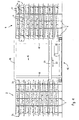
- FIG. 1 Shelf storage shown consists of a left shelf area 2 and a right shelf area 4, in each of which a large number of vertical shelf supports 6 are arranged at a distance from each other, forming a number of horizontal floors 8 in which formed horizontally next to each other a large number of individual shelves each of which is adapted to receive a long goods cassette 10.
- each shelf is provided with friction and wear-reducing coatings so that a Langgutkassette 11 despite the considerable weight of the material received therein (eg rod or plate material) 11 can be easily pulled out or pushed.
- a storage and retrieval unit 14 is guided on rails in a longitudinal direction 16 horizontally movable.
- a vertically oriented cassette holder 20 vertically movable on vertical uprights 18.
- the cassette holder 20 can be driven by the stacker crane frontally before any shelf and serves either to receive a researchernden from the respective shelf Langgutkassette or for storage of a previously recorded in the cassette holder 20 Langgutkassette in the respective shelf.
- the cassette holder 20 for receiving two Langgutkassetten is formed side by side, with two substantially identical, in the longitudinal direction 16 one behind the other arranged receiving channels, in each of which a trolley on a horizontal guide track is moved to To insert a recorded Langgutkassette in a shelf or to pull out an outsourced Langgutkassette from a shelf in the relevant receiving channel of the cassette holder.
- Fig. 1 These trolleys are not shown. Only on the left edge of the cassette holder 20 is seen from this frontally projecting end of a gripper head of a trolley, in engagement with a Kassettenmit distractor 24, as will be explained below.
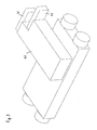
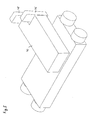
- Fig. 2 to 5 show different schematic representations of an aforementioned transport carriage 30 which is movable within a cassette receptacle 20 in the longitudinal direction 22 on four rotatable about horizontal axes of rotation 32 driving rollers 34.
- the casters 34 are guided in a conventional manner in two horizontal, mutually spaced, in cross-section C-shaped rails, in each of which a horizontal lower and at least spaced by the diameter of the casters horizontal upper roadway is formed. This arrangement ensures that the trolley is safely guided even when tilting moments occur, which are introduced about a horizontal, parallel to the axes of rotation 32 extending axis
- the trolley 30 may in principle be driven in any desired manner in the longitudinal direction 22, for example by driven drive wheels or driving rollers, strand-shaped, in the longitudinal direction of the cassette holder 20 circumferentially arranged traction means such as chains, ropes or the like or by any other linear drive technology.
- the trolley 30 of two parallel in the longitudinal direction 22 of the cassette holder 20 circumferentially stirred drive chains 60, 62 movable, which are connected at a distance from each other and in the vicinity of the rollers 34 with a chassis 36 of the trolley.
- the drive chains are moved by a controlled drive with which a location-accurate positioning of the trolley 30 along the cassette holder 20 is possible.
- the trolley 30 has a gripping device for detecting and moving a long goods cassette in the form of a rotatable around a vertical axis of rotation 38 gripping head 40.
- the gripping head 40 is between an in Fig. 2 and 4 shown first drawing position and a in Fig. 3 and 5 shown pivotable by a certain angle, here 180 °, compared to the first pulling position twisted second drawing position.
- the gripping head 40 carries at a distance to the rotation axis 38, a first or outer gripping member 46 and at a smaller distance from the rotation axis 38, a second or inner gripping member 48, so that between the gripping elements 46, 48, a gap 50 with width B, in the longitudinal direction 22 exists.
- the arrangement is such that the width B of the gap 50 of the width or thickness, seen in the longitudinal direction 22 of the cassette holder 20 and thus also in the longitudinal direction of a respective shelf of the racking, a Kassettemit interventions 24 corresponds to each Langgutkassette at its two opposite Ends is provided, or slightly greater than this thickness, so that the cassette driver can be taken in the manner to be explained below with swung-up gripping elements with some play between them.
- a trolley with a pivotable gripping head, on which only a single pivotable gripping element is arranged is alternatively conceivable for interacting with a cassette driver, which forms a U-shaped receptacle.
- the axis of rotation 38 of the gripping head 40 in the illustrated embodiment is not centered with respect to the width A of the trolley between the casters 34, but eccentrically so that the effective length of the gripper head 40, i. the distance between the center of the gap 50 between the gripping elements 46, 48 of the rotation axis 38, can be formed as large as possible without the gripping elements abut against one of the lateral rails in a rotational movement by 180 °.
- the axis of rotation 38 is thus closer to a pair of drive rollers 34 than to the opposite pair of drive rollers 34, wherein the distance ratio between the axis of rotation 38 and the respective drive rollers may for example be in the range of 1: 1 to 4: 1 and in the illustrated example about 2: 1 amounts to.
- the two gripper elements 46, 48 are independently between the lowered rest position ( Fig. 2 . 3 ) and the raised gripping position ( Fig. 4 . 5 ) movable.
- the gripping elements are designed in the form of pivot levers which are pivotable about a horizontal first pivot axis 52 and a second pivot axis 54.
- the mutual spacing of the first and second pivot axes 52, 54 is selected so that the respective drives can be spaced apart from each other within the gripping head 40 can be accommodated, for example in the form of servo or stepper motors, which allow a controlled pivoting movement.
- a concentric arrangement of the pivot axes 52, 54 is possible, ie mutually coinciding pivot axes.
- a linear guide in a vertical or oblique direction is also possible, so that the gripping elements can be raised or lowered by a displacement along the guide.
- the swivel design shown has the advantage that when relatively flat construction, a relatively large vertical area between the raised and lowered position can be covered.
- the Kassettemit musical 24 which are arranged at both opposite ends of each Langgutkassette have in a conventional manner the shape of a horizontal crossbar with a round cross section (s. Fig. 4 ).
- the diameter of the cross bar is slightly smaller than the width B of the gap between the gripping elements.
- a first pull chain 60 and a second pull chain 62 is indicated, wherein the second pull chain 62 must absorb greater tensile forces during operation due to their smaller distance from the gripping elements 46, 48 and therefore is formed stronger than the first pull chain 60.
- the first pull chain 60 is simple and the second pull chain 62 is double.
- Fig. 6 illustrates in a sequence of four representations, from top to bottom, which are to be understood as a time sequence in succession, a method for retrieving and a method for relocating a long goods cassette from a control warehouse with a storage and retrieval unit according to the invention.
- the uppermost illustration shows the cassette holder 20 frontally before and in the amount of Medicarelagernden a cassette 10, the gripping head 40 of the trolley 30 are pivoted into a pointing to the cassette pulling position in which the gripping elements can detect the 24 Kassettenmit supplements.
- the further away from the axis of rotation of the gripping head first gripper 46 is pivoted up after the trolley has moved behind the cassette driver, and the second, after the trolley has moved back a piece until the first gripping member abuts against the driver.
- the cassette is pulled into the cassette holder by the trolley to the opposite (in Fig. 6 left) end of the cassette holder is driven (second illustration from above).
- the cassette is now located substantially in the middle of the cassette holder and can either be relocated to a shelf of the same shelf area or pushed out after moving out of the storage and retrieval device to a arranged outside of the shelf storage cassette holder.
- the trolley is first moved with lowered gripping elements to the opposite end of the cassette holder and the gripping head rotated in the opposite pulling position. At least the first axis of rotation of the gripping head nearest second gripper 48 is raised to the gripping position, and the trolley can push through cooperation between the gripping member and the Kassettenmit choir the cassette in an opposite shelf after the storage and retrieval unit has driven the cassette holder, if necessary, to the required location.
- the cassette holder To execute an in Fig. 6 explained stock transfer operation, the cassette holder must have a width of the aisle length corresponding to the length of a Langgutkassette, ie the mutual distance of the respective end mounted Kassettenmit counseling 24, plus twice the length of the trolley, measured as a distance about the middle of the gap between the gripping elements of the axis of rotation of the furthest away from driving rollers 34 corresponds.
- a reduction of the lane width and the length of the cassette holder of the storage and retrieval unit and thus also an improved utilization of the base of the rack storage, which is particularly noticeable in the arrangement of numerous rack aisles, can be with the achieve a storage and retrieval device according to the invention in that a in Fig. 7 explained repositioning method is applied.
- the intermediate, required at a narrow Regelgasse conversion process can alternatively be done in a conventional manner with a separate transfer device.
Landscapes
- Engineering & Computer Science (AREA)
- Transportation (AREA)
- Structural Engineering (AREA)
- Mechanical Engineering (AREA)
- Civil Engineering (AREA)
- Life Sciences & Earth Sciences (AREA)
- Geology (AREA)
- Warehouses Or Storage Devices (AREA)
- Vending Machines For Individual Products (AREA)
- Forklifts And Lifting Vehicles (AREA)
- Automatic Tape Cassette Changers (AREA)
Claims (20)
- Transstockeur (14) pour des cassettes, en particulier des cassettes à produit long (10), avec au moins un logement à cassette (20) horizontal, présentant un chariot de transport (30), déplaçable le long d'une piste de guidage horizontale au moyen d'un dispositif d'entraînement (60, 62), chariot de transport muni d'un dispositif de saisie (40, 46, 48) pour chaque fois au moins une cassette (10), le dispositif de saisie présentant une tête de saisie (40) susceptible de tourner autour d'un axe de rotation (38) vertical, entre une première position de traction et une deuxième position de traction, caractérisé en ce que la tête de saisie porte deux éléments de saisie (46, 48) disposés à une distance différente de l'axe de rotation (38), déplaçables indépendamment l'un de l'autre, entre une position de repos abaissée et une position de saisie relevée.
- Transstockeur selon la revendication 1, caractérisé en ce qu'au moins un élément de saisie est déplaçable le long d'un guidage disposé verticalement ou obliquement.
- Transstockeur selon la revendication 1, caractérisé en ce qu'au moins un élément de saisie (46, 48) est maintenu de manière excentrée par rapport à un axe de pivotement (52, 54) horizontal et est susceptible de pivoter autour de celui-ci.
- Transstockeur selon la revendication 3, caractérisé en ce que les éléments de saisie (46, 48) sont susceptibles de pivoter autour d'axes de pivotement (52, 54) parallèles, pouvant être disposés concentriquement ou avec un espacement mutuel.
- Transstockeur selon la revendication 3 ou 4, caractérisé en ce que chaque élément de saisie (46, 48) est susceptible de pivoter d'un angle de pivotement déterminé, de la position de repos à la position de saisie.
- Transstockeur selon la revendication 5, caractérisé en ce que l'angle de pivotement est d'une valeur entre 30° et 120°.
- Transstockeur selon l'une des revendications précédentes, caractérisé en ce qu'au moins un élément de saisie est muni d'un emplacement de rupture préférentielle.
- Transstockeur selon l'une des revendications précédentes, caractérisé en ce que chaque élément de saisie (46, 48) est entraîné de manière commandé électriquement, pneumatiquement ou hydrauliquement, à l'aide d'un servomoteur ou d'un moteur pas à pas.
- Transstockeur selon l'une des revendications précédentes, caractérisé en ce que le chariot de transport (30) est déplaçable sur deux rails de déplacement parallèles, à section transversale en forme de C.
- Transstockeur selon l'une des revendications précédentes, caractérisé en ce que le chariot de transport (30) présente quatre galets de transport (34).
- Transstockeur selon l'une des revendications précédentes, caractérisé en ce que l'axe de rotation (38) vertical est disposé de manière centrée par rapport au chariot de transport (30).
- Transstockeur selon l'une des revendications 1 à 10, caractérisé en ce que l'axe de rotation (38) vertical est disposé de manière excentrée par rapport au chariot de transport (30).
- Transstockeur selon l'une des revendications précédentes, caractérisé en ce que la première et la deuxième position de traction sont distantes l'une de l'autre de 180°.
- Transstockeur selon l'une des revendications précédentes, caractérisé en ce que le chariot de transport (30) est déplaçable au moyen de deux chaînes de traction (60, 62) espacées et parallèles.
- Transstockeur selon les revendications 12 et 14, caractérisé en ce que l'une des chaînes de traction (62), disposée plus près de l'axe de rotation (38) que l'autre (60), présente une résistance à la traction plus élevée, et un allongement sous charge plus faible, que l'autre chaîne de traction (60).
- Stockage sur rayonnages pour des cassettes, en particulier des cassettes à produit long, avec un transstockeur (14) selon l'une des revendications précédentes, le stockage sur rayonnages contenant, sur des appuis de rayonnages (6) verticaux, en plusieurs étages (8), selon des espacements réguliers, des compartiments de rayonnage avec des reposoirs pour les cassettes à produit long (10), le transstockeur (14) étant déplaçable côté frontal, horizontalement et verticalement devant les compartiments de rayonnage et le logement à cassette (20) étant tourné dans la direction d'étendue des cassettes (10).
- Procédé pour désentreposer une cassette, en particulier une cassette à produit long, d'un stockage sur rayonnages avec un transstockeur (14) selon l'une des revendications 1 à 15, comprenant les étapes consistant à :déplacer le logement à cassette (20) côté frontal, devant un compartiment de rayonnage, avec une cassette (10) à désentreposer, faire pivoter la tête de saisie (40) pour la passer en une position de traction, dans laquelle les éléments de saisie (46, 48) sont tournés vers la cassette (10) à désentreposer, les éléments de saisie se trouvant alors en position de repos, déplacer le chariot de transport (30) à une extrémité, voisine de la cassette (10), du logement à cassette (20), jusqu'à ce qu'un premier élément de saisie (46), plus éloigné de l'axe de rotation (38) qu'un deuxième élément de saisie (48), se trouve derrière un organe d'entraînement de cassette (24),déplacer le premier élément de saisie (46) en position de saisie, ramener le chariot de transport (30) et tirer la cassette (10) dans le logement à cassette (20) du transstockeur (14).
- Procédé selon la revendication 17, caractérisé en ce que le deuxième élément de saisie (48) est déplacé en position de saisie après que le premier élément de saisie (46) soit mis en appui contre l'organe d'entraînement de cassette (24).
- Procédé pour transposer une cassette, en particulier une cassette à produit long (10), d'un premier compartiment de rayonnage en un deuxième compartiment de rayonnage d'un stockage sur rayonnages, avec un transstockeur (14) selon l'une des revendications 1 à 15, comprenant les étapes consistant à : a) déplacer le logement à cassette (20) côté frontal, devant le premier compartiment à cassette, b) faire pivoter la tête de saisie (40) pour la passer en une position de traction, dans laquelle les éléments de saisie (46, 48) sont tournés vers la cassette (10) à transposer, les éléments de saisie se trouvant alors en position de repos, c) déplacer le chariot de transport (30) à une extrémité, voisine de la cassette (10), du logement à
cassette (20), jusqu'à ce qu'un premier élément de saisie (46), plus éloigné de l'axe de rotation (38) qu'un deuxième élément de saisie (48), se trouve derrière un organe d'entraînement de cassette (24), d) déplacer le premier élément de saisie (46) en position de saisie, e) ramener le chariot de transport (30) à une extrémité opposée du logement à cassette (20) et tirer la cassette (10) dans le logement à cassette (20) du transstockeur (14), f) déplacer le premier élément de saisie (46) en position de repos, faire pivoter la tête de saisie (40) en une position de saisie opposée et déplacer le chariot de transport (30) à la première extrémité du logement à cassette (20), g) déplacer le logement à cassette côté frontal devant le deuxième compartiment à assette, h) déplacer le deuxième élément de saisie (48) en position de saisie, déplacer le chariot de transport à l'extrémité opposée du logement à cassette (20) et pousser la cassette (10) dans le deuxième compartiment de rayonnage. - Procédé selon la revendication 19, caractérisé en ce que, à l'étape f), avec une tête de saisie (40) tournée en une position de traction opposée, il est parcouru une distance supplémentaire en direction de l'extrémité opposée du logement à cassette (20), correspondant à peu près à un double de l'espacement entre l'axe de rotation (38) vertical de la tête de saisie (40) et le centre de l'espace intermédiaire (50) des éléments de saisie (46, 48) et, ensuite, le premier élément de saisie (46) est déplacé à la position de repos, et le chariot de transport (30) est déplacé à la première extrémité du logement à cassette (20) .
Priority Applications (5)
| Application Number | Priority Date | Filing Date | Title |
|---|---|---|---|
| EP09004680A EP2236451B1 (fr) | 2009-03-31 | 2009-03-31 | Appareil de commande d'étagère pour cassettes de marchandises longitudinales |
| PL09004680T PL2236451T3 (pl) | 2009-03-31 | 2009-03-31 | Urządzenie do obsługi regałów na kasety do długich elementów |
| DE502009000189T DE502009000189D1 (de) | 2009-03-31 | 2009-03-31 | Regalbediengerät für Langgutkassetten |
| ES09004680T ES2356033T3 (es) | 2009-03-31 | 2009-03-31 | Robot de estantería para cartuchos de mercancías alargadas. |
| AT09004680T ATE488468T1 (de) | 2009-03-31 | 2009-03-31 | Regalbediengerät für langgutkassetten |
Applications Claiming Priority (1)
| Application Number | Priority Date | Filing Date | Title |
|---|---|---|---|
| EP09004680A EP2236451B1 (fr) | 2009-03-31 | 2009-03-31 | Appareil de commande d'étagère pour cassettes de marchandises longitudinales |
Publications (2)
| Publication Number | Publication Date |
|---|---|
| EP2236451A1 EP2236451A1 (fr) | 2010-10-06 |
| EP2236451B1 true EP2236451B1 (fr) | 2010-11-17 |
Family
ID=41009334
Family Applications (1)
| Application Number | Title | Priority Date | Filing Date |
|---|---|---|---|
| EP09004680A Active EP2236451B1 (fr) | 2009-03-31 | 2009-03-31 | Appareil de commande d'étagère pour cassettes de marchandises longitudinales |
Country Status (5)
| Country | Link |
|---|---|
| EP (1) | EP2236451B1 (fr) |
| AT (1) | ATE488468T1 (fr) |
| DE (1) | DE502009000189D1 (fr) |
| ES (1) | ES2356033T3 (fr) |
| PL (1) | PL2236451T3 (fr) |
Family Cites Families (5)
| Publication number | Priority date | Publication date | Assignee | Title |
|---|---|---|---|---|
| JPS6341302A (ja) * | 1986-08-08 | 1988-02-22 | Koyo Autom Mach Co Ltd | 自動倉庫 |
| HU196569B (en) * | 1986-09-09 | 1988-12-28 | Intranszmas Magyar Bolgar Tars | Casette moving device particularly for moving strand materials arranged in casette |
| DE4204358A1 (de) * | 1992-02-14 | 1993-08-19 | Robotech Logistiksysteme Gmbh | Regalbediengeraet zum bedienen von lager- und ablaufplaetzen insbesondere eines regallagers |
| DE102005039466B4 (de) | 2005-08-20 | 2007-06-06 | Friedrich Remmert Gmbh & Co. Kg | Regallager mit einem Regalbediengerät |
| ATE528235T1 (de) * | 2007-10-29 | 2011-10-15 | Hen S R L | Automatisches lagerhaus |
-
2009
- 2009-03-31 PL PL09004680T patent/PL2236451T3/pl unknown
- 2009-03-31 EP EP09004680A patent/EP2236451B1/fr active Active
- 2009-03-31 ES ES09004680T patent/ES2356033T3/es active Active
- 2009-03-31 DE DE502009000189T patent/DE502009000189D1/de active Active
- 2009-03-31 AT AT09004680T patent/ATE488468T1/de active
Also Published As
| Publication number | Publication date |
|---|---|
| ATE488468T1 (de) | 2010-12-15 |
| EP2236451A1 (fr) | 2010-10-06 |
| ES2356033T3 (es) | 2011-04-04 |
| DE502009000189D1 (de) | 2010-12-30 |
| PL2236451T3 (pl) | 2011-04-29 |
Similar Documents
| Publication | Publication Date | Title |
|---|---|---|
| EP1695925B1 (fr) | Magasin à rayonnage et procédé pour transférer d'articles dans un magasin à rayonnage | |
| EP3286111B1 (fr) | Procédé de mise en stock de charges isolées dans un rayonnage de stockage et système de stockage | |
| EP2234905B1 (fr) | Procédé et dispositif de transport pour positionner des moyens de chargement avant leur transfert dans un compartiment de rayonnage | |
| EP2100831B1 (fr) | Véhicule de transport pour palettes et système de transport | |
| EP2433882B1 (fr) | Dispositif pour le stockage de produits | |
| DE102013006391A1 (de) | Bedienfahrzeug, Verfahren zum Bewegen eines Bedienfahrzeugs an einer Lagerregal-Anordnung und Lagerregal-Anordnung | |
| EP3475212B1 (fr) | Entrepôt à haut rayonnage comprenant, à l'intérieur, des transstockeurs destinés à stocker et déstocker ou transférer des marchandises entreposées | |
| DE102012220193A1 (de) | Lagergut-Extraktor für ein automatisches Lagersystem | |
| EP4363352A1 (fr) | Procédé de stockage ou de récupération d'auxiliaires de stockage | |
| DE102017107695A1 (de) | Flurförderzeug mit Schubeinrichtung | |
| EP2236451B1 (fr) | Appareil de commande d'étagère pour cassettes de marchandises longitudinales | |
| EP0987384B1 (fr) | Dispositif d'enmagasinage et de démagasinage de véhicules automobiles dans un garage à étages | |
| DE4432856C2 (de) | Aufnahmevorrichtung für Paletten | |
| EP0775665B1 (fr) | Dispositif pour l'extraction et l'insertion de merchandises dans un magasin de grande hauteur | |
| EP1357061B1 (fr) | Chariot de transport pour rayonnage d'entrepôt et vehicule d'entrepôt avec un tel chariot | |
| EP1862405B1 (fr) | Procédé destiné à saisir une marchandise à l'aide d'éléments de préhension dans un dispositif de stockage et de déstockage et dispositif correspondant | |
| DD262221A5 (de) | Kassettenbewegungswerk, insb. zum bewegen von in kassetten untergebrachten stabstahlguetern | |
| EP3205607B1 (fr) | Procédé et dispositif de transport d'un rayonnage d'un véhicule de transport | |
| EP1285866B1 (fr) | Magasin à rayonnage pour boItes rectangulaires en particulier des boItes à dimensions standardisées | |
| CH696687A5 (de) | Regallager mit verschiebbaren Toren. | |
| EP3527507B1 (fr) | Dispositif de préparation de commandes et chariot de préparation de commandes pour un entrepôt à rayonnages | |
| EP1449794B1 (fr) | Rayonnage à bras en porte-à-faux, système de stockage et méthode de stockage | |
| EP2039850A2 (fr) | Construction pour garer des véhicules | |
| EP1831096B1 (fr) | Procede et dispositif pour manipuler au moins un article | |
| EP3947204A1 (fr) | Entrepôt à haut rayonnage pour marchandises à suspendre |
Legal Events
| Date | Code | Title | Description |
|---|---|---|---|
| GRAP | Despatch of communication of intention to grant a patent |
Free format text: ORIGINAL CODE: EPIDOSNIGR1 |
|
| GRAS | Grant fee paid |
Free format text: ORIGINAL CODE: EPIDOSNIGR3 |
|
| PUAI | Public reference made under article 153(3) epc to a published international application that has entered the european phase |
Free format text: ORIGINAL CODE: 0009012 |
|
| 17P | Request for examination filed |
Effective date: 20091005 |
|
| AK | Designated contracting states |
Kind code of ref document: A1 Designated state(s): AT BE BG CH CY CZ DE DK EE ES FI FR GB GR HR HU IE IS IT LI LT LU LV MC MK MT NL NO PL PT RO SE SI SK TR |
|
| AX | Request for extension of the european patent |
Extension state: AL |
|
| GRAA | (expected) grant |
Free format text: ORIGINAL CODE: 0009210 |
|
| AK | Designated contracting states |
Kind code of ref document: B1 Designated state(s): AT BE BG CH CY CZ DE DK EE ES FI FR GB GR HR HU IE IS IT LI LT LU LV MC MK MT NL NO PL PT RO SE SI SK TR |
|
| REG | Reference to a national code |
Ref country code: GB Ref legal event code: FG4D Free format text: NOT ENGLISH |
|
| REG | Reference to a national code |
Ref country code: CH Ref legal event code: EP |
|
| REG | Reference to a national code |
Ref country code: IE Ref legal event code: FG4D |
|
| REF | Corresponds to: |
Ref document number: 502009000189 Country of ref document: DE Date of ref document: 20101230 Kind code of ref document: P |
|
| REG | Reference to a national code |
Ref country code: CH Ref legal event code: NV Representative=s name: NOVAGRAAF INTERNATIONAL SA |
|
| REG | Reference to a national code |
Ref country code: NL Ref legal event code: VDEP Effective date: 20101117 |
|
| REG | Reference to a national code |
Ref country code: ES Ref legal event code: FG2A Ref document number: 2356033 Country of ref document: ES Kind code of ref document: T3 Effective date: 20110404 |
|
| LTIE | Lt: invalidation of european patent or patent extension |
Effective date: 20101117 |
|
| PG25 | Lapsed in a contracting state [announced via postgrant information from national office to epo] |
Ref country code: NO Free format text: LAPSE BECAUSE OF FAILURE TO SUBMIT A TRANSLATION OF THE DESCRIPTION OR TO PAY THE FEE WITHIN THE PRESCRIBED TIME-LIMIT Effective date: 20110217 Ref country code: LT Free format text: LAPSE BECAUSE OF FAILURE TO SUBMIT A TRANSLATION OF THE DESCRIPTION OR TO PAY THE FEE WITHIN THE PRESCRIBED TIME-LIMIT Effective date: 20101117 |
|
| REG | Reference to a national code |
Ref country code: PL Ref legal event code: T3 |
|
| PG25 | Lapsed in a contracting state [announced via postgrant information from national office to epo] |
Ref country code: HR Free format text: LAPSE BECAUSE OF FAILURE TO SUBMIT A TRANSLATION OF THE DESCRIPTION OR TO PAY THE FEE WITHIN THE PRESCRIBED TIME-LIMIT Effective date: 20101117 Ref country code: PT Free format text: LAPSE BECAUSE OF FAILURE TO SUBMIT A TRANSLATION OF THE DESCRIPTION OR TO PAY THE FEE WITHIN THE PRESCRIBED TIME-LIMIT Effective date: 20110317 Ref country code: IS Free format text: LAPSE BECAUSE OF FAILURE TO SUBMIT A TRANSLATION OF THE DESCRIPTION OR TO PAY THE FEE WITHIN THE PRESCRIBED TIME-LIMIT Effective date: 20110317 Ref country code: FI Free format text: LAPSE BECAUSE OF FAILURE TO SUBMIT A TRANSLATION OF THE DESCRIPTION OR TO PAY THE FEE WITHIN THE PRESCRIBED TIME-LIMIT Effective date: 20101117 Ref country code: SE Free format text: LAPSE BECAUSE OF FAILURE TO SUBMIT A TRANSLATION OF THE DESCRIPTION OR TO PAY THE FEE WITHIN THE PRESCRIBED TIME-LIMIT Effective date: 20101117 Ref country code: SI Free format text: LAPSE BECAUSE OF FAILURE TO SUBMIT A TRANSLATION OF THE DESCRIPTION OR TO PAY THE FEE WITHIN THE PRESCRIBED TIME-LIMIT Effective date: 20101117 Ref country code: CY Free format text: LAPSE BECAUSE OF FAILURE TO SUBMIT A TRANSLATION OF THE DESCRIPTION OR TO PAY THE FEE WITHIN THE PRESCRIBED TIME-LIMIT Effective date: 20101117 Ref country code: BG Free format text: LAPSE BECAUSE OF FAILURE TO SUBMIT A TRANSLATION OF THE DESCRIPTION OR TO PAY THE FEE WITHIN THE PRESCRIBED TIME-LIMIT Effective date: 20110217 Ref country code: LV Free format text: LAPSE BECAUSE OF FAILURE TO SUBMIT A TRANSLATION OF THE DESCRIPTION OR TO PAY THE FEE WITHIN THE PRESCRIBED TIME-LIMIT Effective date: 20101117 Ref country code: NL Free format text: LAPSE BECAUSE OF FAILURE TO SUBMIT A TRANSLATION OF THE DESCRIPTION OR TO PAY THE FEE WITHIN THE PRESCRIBED TIME-LIMIT Effective date: 20101117 |
|
| REG | Reference to a national code |
Ref country code: CH Ref legal event code: PFA Owner name: REMMERT GMBH & CO. KG Free format text: REMMERT GMBH & CO. KG#BRUNNENSTRASSE 113#32584 LOEHNE (DE) -TRANSFER TO- REMMERT GMBH & CO. KG#BRUNNENSTRASSE 113#32584 LOEHNE (DE) |
|
| AKX | Designation fees paid |
Designated state(s): AT BE BG CH CY CZ DE DK EE ES FI FR GB GR HR HU IE IS IT LI LT LU LV MC MK MT NL NO PL PT RO SE SI SK TR |
|
| REG | Reference to a national code |
Ref country code: IE Ref legal event code: FD4D |
|
| PG25 | Lapsed in a contracting state [announced via postgrant information from national office to epo] |
Ref country code: GR Free format text: LAPSE BECAUSE OF FAILURE TO SUBMIT A TRANSLATION OF THE DESCRIPTION OR TO PAY THE FEE WITHIN THE PRESCRIBED TIME-LIMIT Effective date: 20110218 |
|
| PG25 | Lapsed in a contracting state [announced via postgrant information from national office to epo] |
Ref country code: IE Free format text: LAPSE BECAUSE OF FAILURE TO SUBMIT A TRANSLATION OF THE DESCRIPTION OR TO PAY THE FEE WITHIN THE PRESCRIBED TIME-LIMIT Effective date: 20101117 Ref country code: CZ Free format text: LAPSE BECAUSE OF FAILURE TO SUBMIT A TRANSLATION OF THE DESCRIPTION OR TO PAY THE FEE WITHIN THE PRESCRIBED TIME-LIMIT Effective date: 20101117 Ref country code: EE Free format text: LAPSE BECAUSE OF FAILURE TO SUBMIT A TRANSLATION OF THE DESCRIPTION OR TO PAY THE FEE WITHIN THE PRESCRIBED TIME-LIMIT Effective date: 20101117 |
|
| PG25 | Lapsed in a contracting state [announced via postgrant information from national office to epo] |
Ref country code: SK Free format text: LAPSE BECAUSE OF FAILURE TO SUBMIT A TRANSLATION OF THE DESCRIPTION OR TO PAY THE FEE WITHIN THE PRESCRIBED TIME-LIMIT Effective date: 20101117 Ref country code: DK Free format text: LAPSE BECAUSE OF FAILURE TO SUBMIT A TRANSLATION OF THE DESCRIPTION OR TO PAY THE FEE WITHIN THE PRESCRIBED TIME-LIMIT Effective date: 20101117 |
|
| PLBE | No opposition filed within time limit |
Free format text: ORIGINAL CODE: 0009261 |
|
| STAA | Information on the status of an ep patent application or granted ep patent |
Free format text: STATUS: NO OPPOSITION FILED WITHIN TIME LIMIT |
|
| BERE | Be: lapsed |
Owner name: REMMERT G.M.B.H. & CO. KG Effective date: 20110331 |
|
| 26N | No opposition filed |
Effective date: 20110818 |
|
| PG25 | Lapsed in a contracting state [announced via postgrant information from national office to epo] |
Ref country code: MC Free format text: LAPSE BECAUSE OF NON-PAYMENT OF DUE FEES Effective date: 20110331 |
|
| REG | Reference to a national code |
Ref country code: DE Ref legal event code: R097 Ref document number: 502009000189 Country of ref document: DE Effective date: 20110818 |
|
| PG25 | Lapsed in a contracting state [announced via postgrant information from national office to epo] |
Ref country code: BE Free format text: LAPSE BECAUSE OF NON-PAYMENT OF DUE FEES Effective date: 20110331 Ref country code: MT Free format text: LAPSE BECAUSE OF FAILURE TO SUBMIT A TRANSLATION OF THE DESCRIPTION OR TO PAY THE FEE WITHIN THE PRESCRIBED TIME-LIMIT Effective date: 20101117 |
|
| PG25 | Lapsed in a contracting state [announced via postgrant information from national office to epo] |
Ref country code: MK Free format text: LAPSE BECAUSE OF FAILURE TO SUBMIT A TRANSLATION OF THE DESCRIPTION OR TO PAY THE FEE WITHIN THE PRESCRIBED TIME-LIMIT Effective date: 20101117 |
|
| PG25 | Lapsed in a contracting state [announced via postgrant information from national office to epo] |
Ref country code: LU Free format text: LAPSE BECAUSE OF NON-PAYMENT OF DUE FEES Effective date: 20110331 |
|
| PG25 | Lapsed in a contracting state [announced via postgrant information from national office to epo] |
Ref country code: TR Free format text: LAPSE BECAUSE OF FAILURE TO SUBMIT A TRANSLATION OF THE DESCRIPTION OR TO PAY THE FEE WITHIN THE PRESCRIBED TIME-LIMIT Effective date: 20101117 |
|
| PG25 | Lapsed in a contracting state [announced via postgrant information from national office to epo] |
Ref country code: HU Free format text: LAPSE BECAUSE OF FAILURE TO SUBMIT A TRANSLATION OF THE DESCRIPTION OR TO PAY THE FEE WITHIN THE PRESCRIBED TIME-LIMIT Effective date: 20101117 |
|
| PG25 | Lapsed in a contracting state [announced via postgrant information from national office to epo] |
Ref country code: RO Free format text: LAPSE BECAUSE OF FAILURE TO SUBMIT A TRANSLATION OF THE DESCRIPTION OR TO PAY THE FEE WITHIN THE PRESCRIBED TIME-LIMIT Effective date: 20101117 |
|
| REG | Reference to a national code |
Ref country code: FR Ref legal event code: PLFP Year of fee payment: 8 |
|
| REG | Reference to a national code |
Ref country code: FR Ref legal event code: PLFP Year of fee payment: 9 |
|
| REG | Reference to a national code |
Ref country code: FR Ref legal event code: PLFP Year of fee payment: 10 |
|
| REG | Reference to a national code |
Ref country code: ES Ref legal event code: PC2A Owner name: REMMERET HOLDING GMBH & CO. KG. Effective date: 20200428 Ref country code: DE Ref legal event code: R082 Ref document number: 502009000189 Country of ref document: DE Representative=s name: BOEHMERT & BOEHMERT ANWALTSPARTNERSCHAFT MBB -, DE Ref country code: DE Ref legal event code: R081 Ref document number: 502009000189 Country of ref document: DE Owner name: REMMERT HOLDING GMBH & CO. KG, DE Free format text: FORMER OWNER: REMMERT GMBH & CO. KG, 32584 LOEHNE, DE |
|
| REG | Reference to a national code |
Ref country code: CH Ref legal event code: NV Representative=s name: ISLER AND PEDRAZZINI AG, CH Ref country code: CH Ref legal event code: PFA Owner name: REMMERT HOLDING GMBH AND CO. KG, DE Free format text: FORMER OWNER: REMMERT GMBH AND CO. KG, DE |
|
| REG | Reference to a national code |
Ref country code: AT Ref legal event code: HC Ref document number: 488468 Country of ref document: AT Kind code of ref document: T Owner name: REMMERT HOLDING GMBH & CO. KG, DE Effective date: 20200901 |
|
| PGFP | Annual fee paid to national office [announced via postgrant information from national office to epo] |
Ref country code: FR Payment date: 20230320 Year of fee payment: 15 |
|
| PGFP | Annual fee paid to national office [announced via postgrant information from national office to epo] |
Ref country code: PL Payment date: 20230320 Year of fee payment: 15 |
|
| PGFP | Annual fee paid to national office [announced via postgrant information from national office to epo] |
Ref country code: IT Payment date: 20230331 Year of fee payment: 15 Ref country code: ES Payment date: 20230414 Year of fee payment: 15 Ref country code: DE Payment date: 20230331 Year of fee payment: 15 Ref country code: CH Payment date: 20230402 Year of fee payment: 15 |
|
| PGFP | Annual fee paid to national office [announced via postgrant information from national office to epo] |
Ref country code: AT Payment date: 20240318 Year of fee payment: 16 |
|
| PGFP | Annual fee paid to national office [announced via postgrant information from national office to epo] |
Ref country code: GB Payment date: 20240322 Year of fee payment: 16 |