EP2236366B1 - Windscreen wiper device - Google Patents
Windscreen wiper device Download PDFInfo
- Publication number
- EP2236366B1 EP2236366B1 EP09157195A EP09157195A EP2236366B1 EP 2236366 B1 EP2236366 B1 EP 2236366B1 EP 09157195 A EP09157195 A EP 09157195A EP 09157195 A EP09157195 A EP 09157195A EP 2236366 B1 EP2236366 B1 EP 2236366B1
- Authority
- EP
- European Patent Office
- Prior art keywords
- connecting device
- wiper blade
- legs
- windscreen
- wiper
- Prior art date
- Legal status (The legal status is an assumption and is not a legal conclusion. Google has not performed a legal analysis and makes no representation as to the accuracy of the status listed.)
- Active
Links
Images


Classifications
-
- B—PERFORMING OPERATIONS; TRANSPORTING
- B60—VEHICLES IN GENERAL
- B60S—SERVICING, CLEANING, REPAIRING, SUPPORTING, LIFTING, OR MANOEUVRING OF VEHICLES, NOT OTHERWISE PROVIDED FOR
- B60S1/00—Cleaning of vehicles
- B60S1/02—Cleaning windscreens, windows or optical devices
- B60S1/04—Wipers or the like, e.g. scrapers
- B60S1/32—Wipers or the like, e.g. scrapers characterised by constructional features of wiper blade arms or blades
- B60S1/38—Wiper blades
- B60S1/3848—Flat-type wiper blade, i.e. without harness
- B60S1/3849—Connectors therefor; Connection to wiper arm; Attached to blade
- B60S1/3851—Mounting of connector to blade assembly
- B60S1/3856—Gripping the blade
-
- B—PERFORMING OPERATIONS; TRANSPORTING
- B60—VEHICLES IN GENERAL
- B60S—SERVICING, CLEANING, REPAIRING, SUPPORTING, LIFTING, OR MANOEUVRING OF VEHICLES, NOT OTHERWISE PROVIDED FOR
- B60S1/00—Cleaning of vehicles
- B60S1/02—Cleaning windscreens, windows or optical devices
- B60S1/04—Wipers or the like, e.g. scrapers
- B60S1/32—Wipers or the like, e.g. scrapers characterised by constructional features of wiper blade arms or blades
- B60S1/38—Wiper blades
- B60S1/3806—Means, or measures taken, for influencing the aerodynamic quality of the wiper blades
- B60S1/3808—Spoiler integral with the squeegee
-
- B—PERFORMING OPERATIONS; TRANSPORTING
- B60—VEHICLES IN GENERAL
- B60S—SERVICING, CLEANING, REPAIRING, SUPPORTING, LIFTING, OR MANOEUVRING OF VEHICLES, NOT OTHERWISE PROVIDED FOR
- B60S1/00—Cleaning of vehicles
- B60S1/02—Cleaning windscreens, windows or optical devices
- B60S1/04—Wipers or the like, e.g. scrapers
- B60S1/32—Wipers or the like, e.g. scrapers characterised by constructional features of wiper blade arms or blades
- B60S1/38—Wiper blades
- B60S1/3848—Flat-type wiper blade, i.e. without harness
- B60S1/3849—Connectors therefor; Connection to wiper arm; Attached to blade
- B60S1/3851—Mounting of connector to blade assembly
- B60S1/3853—Snap-fit, e.g. elastic connection
-
- B—PERFORMING OPERATIONS; TRANSPORTING
- B60—VEHICLES IN GENERAL
- B60S—SERVICING, CLEANING, REPAIRING, SUPPORTING, LIFTING, OR MANOEUVRING OF VEHICLES, NOT OTHERWISE PROVIDED FOR
- B60S1/00—Cleaning of vehicles
- B60S1/02—Cleaning windscreens, windows or optical devices
- B60S1/04—Wipers or the like, e.g. scrapers
- B60S1/32—Wipers or the like, e.g. scrapers characterised by constructional features of wiper blade arms or blades
- B60S1/38—Wiper blades
- B60S1/3848—Flat-type wiper blade, i.e. without harness
- B60S1/3849—Connectors therefor; Connection to wiper arm; Attached to blade
- B60S1/3851—Mounting of connector to blade assembly
- B60S1/3858—Mounting of connector to blade assembly with protrusions cooperating with holes
-
- B—PERFORMING OPERATIONS; TRANSPORTING
- B60—VEHICLES IN GENERAL
- B60S—SERVICING, CLEANING, REPAIRING, SUPPORTING, LIFTING, OR MANOEUVRING OF VEHICLES, NOT OTHERWISE PROVIDED FOR
- B60S1/00—Cleaning of vehicles
- B60S1/02—Cleaning windscreens, windows or optical devices
- B60S1/04—Wipers or the like, e.g. scrapers
- B60S1/32—Wipers or the like, e.g. scrapers characterised by constructional features of wiper blade arms or blades
- B60S1/38—Wiper blades
- B60S1/3848—Flat-type wiper blade, i.e. without harness
- B60S1/3849—Connectors therefor; Connection to wiper arm; Attached to blade
- B60S1/3865—Connectors having an integral pivot pin for connection with the wiper arm
- B60S1/3868—Connectors having an integral pivot pin for connection with the wiper arm pin formed on the exterior of side walls
-
- B—PERFORMING OPERATIONS; TRANSPORTING
- B60—VEHICLES IN GENERAL
- B60S—SERVICING, CLEANING, REPAIRING, SUPPORTING, LIFTING, OR MANOEUVRING OF VEHICLES, NOT OTHERWISE PROVIDED FOR
- B60S1/00—Cleaning of vehicles
- B60S1/02—Cleaning windscreens, windows or optical devices
- B60S1/04—Wipers or the like, e.g. scrapers
- B60S1/32—Wipers or the like, e.g. scrapers characterised by constructional features of wiper blade arms or blades
- B60S1/38—Wiper blades
- B60S1/3848—Flat-type wiper blade, i.e. without harness
- B60S1/3874—Flat-type wiper blade, i.e. without harness with a reinforcing vertebra
- B60S1/3875—Flat-type wiper blade, i.e. without harness with a reinforcing vertebra rectangular section
- B60S1/3877—Flat-type wiper blade, i.e. without harness with a reinforcing vertebra rectangular section embedded in the squeegee
Definitions
- the present invention relates to a windscreen wiper device comprising an elastic, elongated carrier element, as well as an elongated wiper blade of a flexible material, which can be placed in abutment with a windscreen to be wiped, which wiper blade includes at least one longitudinal groove, in which groove at least one longitudinal strip of the carrier element is disposed, which windscreen wiper device comprises a connecting device for an oscillating arm, wherein said oscillating arm can be pivotally connected to said connecting device about a pivot axis near one end thereof, with the interposition of a joint part, wherein said wiper blade comprises a spoiler at a side thereof facing away from the windscreen to be wiped, wherein an interior space is left open between said connecting device and said wiper blade at the location of their interconnection, wherein said space forms a water channel for transporting rain water therethrough from a first side of said connecting device facing away from said free end of said oscillating arm to a second side of said connecting device facing towards said free end of said oscillating arm,
- Such a windscreen wiper device is generally known, for example from European patent publication no. 1 876 073 of the same Applicant.
- This prior art windscreen wiper device is designed as a so-called “flat blade” or “yokeless blade", wherein no use is made of several yokes pivotally connected to each other, but wherein the wiper blade is biassed by the carrier element, as a result of which it exhibits a specific curvature.
- the spoiler is also called an "air deflector".
- the object of the invention is to provide an improved windscreen wiper device.
- a windscreen wiper device of the type referred to in the introduction is characterized according to the invention in that said connecting device has a substantially U-shaped cross-section, wherein legs of said U-shaped cross-section are connected to the flexible material of said wiper blade on opposite sides thereof, wherein said legs are movable from an open position, wherein said wiper blade can be placed inside said connecting device at the location of their interconnection, to a closed position, and wherein said legs are clamped around the flexible material of said wiper blade, wherein said longitudinal strip is provided along its interior and/or exterior edge with at least one recess cooperating with a corresponding protrusion on the connecting device, and/or wherein said longitudinal stripis provided with at least one upwardly extending protrusion cooperating with a corresponding recess on the connecting device.
- Said water channel preferably extends in longitudinal direction of said connecting device. In practice also the air flow due to the wind contributes to the existence of an under pressure at the location of said second side.
- the present invention is not restricted to the use of only one longitudinal strip forming the elastic carrier element that is particularly located in a central longitudinal groove of the wiper blade.
- said carrier element may also comprise two longitudinal strips, wherein said strips are disposed in opposite longitudinal grooves of the wiper blade.
- said spoiler continuously extends along the length of said wiper blade, wherein said space is defined between said connecting device and said spoiler.
- said spoiler is not made of two sub-spoilers mounted on opposite sides of the connecting device and extending from the connecting device to a respective connecting piece of the windscreen wiper device.
- said spoiler extends in its entirety from one connecting piece, through the connecting device (that is between the legs of the U-shaped cross-section thereof), to the other connecting device. Consequently, the wiping properties of the present wiper blade are improved, also because rain water is efficiently guided along the entire spoiler in order to be wept away by the oscillatory movement of said oscillating arm.
- Said spoiler is preferably made in one piece with said wiper blade.
- said legs are particularly pushed against a spring force (as a result of the elasticity of the material from which the connecting device is made) from the closed position into the open position, wherein said legs are allowed to automatically spring back from said open position into said closed position.
- a windscreen wiper device in accordance with the invention in said closed position said wiper blade and said longitudinal strip mutually fixated by said legs at the location of the interconnection of said connecting device and said wiper blade, wherein in said closed position said wiper blade is allowed to move in longitudinal direction relative to said longitudinal strip outside the location of the interconnection of said connecting device and said wiper blade.
- the wiper blade and the longitudinal strip are not allowed to mutually move under the connecting device, but in all other areas along the wiper blade a slight movement thereof is made possible in order to allow said wiper blade to follow any curvature of the windscreen to be wiped.
- said legs are particularly slightly deforming (the rubber of) said wiper blade at the location of the interconnection of said connecting device and said wiper blade.
- said joint part is detachably connected to said connecting device by engaging protrusions of said connecting device, at the location of said pivot axis, in recesses provided in said joint part. This is preferably realized through a snapping or clipping operation.
- said joint part has an at least substantially U-shaped cross-section at the location of its connection to said connecting device, and wherein said joint part is provided with a recess provided coaxially with said pivot axis.
- the protrusions extend outwards on either side of said connecting device and are preferably cylindrical in shape.
- said protrusions are spherical or frusto-conical in shape. Said protrusions that function as bearing surfaces are thus paced far apart, so that forces exerted thereon will be relatively low.
- said joint part is provided with co-axial through holes in legs of said U-shaped cross-section thereof, wherein a pivot pin is inserted in said through holes.
- said protrusions are provided with co-axial through holes. Accordingly, the wiper blade may then be connected to the oscillating arm on the basis of a so-called "sidelock system".
- the oscillating arm is provided with a joint pin or a pivot pin to be inserted in said co-axial through holes. Said pivot pin protrudes in a direction towards the wiper blade and has a pivot axis extending in a direction of the oscillating movement of the oscillating arm.
- said joint part comprises at least one resilient tongue engaging in a correspondingly shaped hole provided in a base of a U-shaped cross-section of said oscillating arm, and wherein said resilient tongue is rotatable along a hinge axis between an outward position retaining said wiper blade onto said oscillating arm and an inward position releasing said wiper blade from said oscillating arm. Accordingly, the wiper blade may then be connected to the oscillating arm on the basis of a so-called "toplock system" on the basis of a bayonet connection.
- the resilient tongue In order to connect the wiper blade onto the oscillating arm, the resilient tongue is initially pushed in against a spring force - as if it were a push button - and then allowed to spring back into the hole provided in the oscillating arm, thus snapping, that is clipping the resilient tongue into the hole. By subsequently pushing in again the resilient tongue against the spring force, the wiper blade may be released from the oscillating arm.
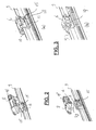
- FIG. 1 shows a preferred variant of a windscreen wiper device 1 according to the invention.
- Said windscreen wiper device is built up of an elastomeric wiper blade 2 comprising a central longitudinal groove 3, wherein a longitudinal strip 4 made of spring band steel is fitted in said longitudinal groove 3 (see figures 5 , 6 and 7 ).
- Said strip 4 forms a flexible carrier element for the rubber wiper blade 2, as it were, which is thus biassed in a curved position (the curvature in operative position being that of a windscreen to be wiped).
- An end of said strip 4 and/or an end of said wiper blade 2 is connected on either side of the windscreen wiper device 1 to respective connecting pieces or "end caps" 5.
- the connecting pieces 5 are separate constructional elements, which may be form-locked as well as force-locked to both ends of said strip 4 and/or ends of said wiper blade 2.
- said connecting pieces 5 are in one piece with the strip 4 made of spring band steel.
- the windscreen wiper device 1 is furthermore built up of a connecting device 6 of metal for connecting an oscillating wiper arm 7 thereto, with the interposition of a joint part 8.
- the oscillating wiper arm 7 is pivotally connected to the connecting device 6 about a pivot axis near one end.
- the preferred embodiment of figure 1 according to the invention comprises a spoiler or "air deflector" 9 which is made in one piece with the rubber wiper blade 2 and which extends along the entire length thereof. This will be explained more in detail below.
- said oscillating arm 7 is connected to a mounting head fixed for rotation to a shaft driven by a small motor.
- the shaft rotates alternately in a clockwise and in a counter-clockwise sense carrying the mounting head into rotation also, which in turn draws said oscillating arm 7 into rotation and by means of said connecting device 6 moves said wiper blade 2.
- FIG 2 an exploded view is given of a part of the windscreen wiper device 1 of figure 1 , showing the connecting device 6 according to a first preferred embodiment, as well as the joint part 8 of figure 1 .
- Figure 3a shows in detail the connecting device 6 according to the first preferred embodiment of figure 2
- FIG 3b the connecting device 6 according to a second preferred embodiment is shown.
- said connecting devices 6 have a U-shaped cross-section, wherein legs 10,19 of said U-shaped cross-section are connected to the rubber of said wiper blade 2 on opposite sides thereof.
- the spoiler 9 extends in its entirety from one connecting piece 5 on one end of the windscreen wiper device 1, through the connecting device 6, i.e. between the legs 10,19 of the U-shaped cross-section thereof, to the other connecting device 5 on the other end of the windscreen wiper device 1.
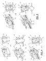
- FIGs 4 and 5 show in perspective and in cross-section the working principle of the connecting device 6 according to the first preferred embodiment, as shown in figure 3a .
- this connecting device 6 has a U-shaped cross-section with said legs 10 and a base 11.
- said legs 10 are moved from a non-operative position, as shown in figure 4a , into an open position, as shown in figure 4b .
- said tool 12 pushes in the direction of arrows 13 said legs 10 outwardly against a spring force of the metal from which the connecting device 6 is manufactured. This is possible as a result of the elastical properties of the metal.
- said wiper blade 2 is mounted inside said connecting device 6 at the location of their interconnection in the direction of arrow 14, to an intermediate position, as shown in figure 4c .
- the longitudinal strip 4 of the carrier element is slided into the central longitudinal groove 3 of the wiper blade 2, as shown in figure 5a .
- a lubricant is used to facilitate insertion of the longitudinal strip 4 inside said longitudinal groove 3.
- said legs 10 of said connecting device 6 are allowed to spring back into a closed position ( figure 5b ), wherein said legs 10 are clamped around said wiper blade 2, while slightly deforming the rubber of said wiper blade 2 at the location where the legs 10 engage the rubber.
- said wiper blade 2 and said longitudinal strip 4 are mutually fixated by said legs 10 at the location of the interconnection of said connecting device 6 and said wiper blade 2, whereas in said closed position said wiper blade 2 is allowed to move in longitudinal direction relative to said longitudinal strip 4 outside the location of the interconnection of said connecting device 6 and said wiper blade 2.
- the connecting device 6 comprises two cylindrical protrusions 15 extending outwards on either side of said connecting device 6. These protrusions 15 pivotally engage in identically shaped cylindrical recesses 16 of the plastic joint part 8. Said protrusions 15 act as bearing surfaces at the location of the pivot axis in order to pivot the joint part 8 (and the oscillating arm 7 attached thereto) about the pivot axis near one end of the oscillating arm 7.
- the protrusions 15 are preferably in one piece with said connecting device 6. In the alternative, said protrusions 15 are part of a single pivot pin perpendicular to the connecting device 6.
- the joint part 8 comprises a resilient tongue 16 extending outwardly, while the oscillating arm 7 has an U-shaped cross-section at the location of its connection to said joint part 8, so that the tongue 17' engages in an identically shaped hole 17" provided in a base of said U-shaped cross-section.
- the connecting device 6 with the wiper blade 2 is mounted onto the oscillating arm 7 as follows.
- the joint part 8 being already clipped onto the connecting device 6 is pivoted relative to the connecting device 6, so that said joint part 8 can be easily slided on a free end of the oscillating arm 7.
- an interior space 18 is left open between said connecting device 6 and said wiper blade 2/spoiler 9 at the location of their interconnection.
- said space 18 is defined by said spoiler 9 of the wiper blade 2, as well as the legs 10 and the base 11 of the connecting device 6.
- Said interior space 18 functions as a water channel extending in longitudinal direction of said connecting device 6. During use said water channel transports rain water therethrough. In other words, in use rain water is carried away from a first side of said connecting device 6 facing away from said free end of said oscillating 7 arm to a second side of said connecting device 6 facing towards said free end of said oscillating arm 7.
- Figures 6 and 7 show in perspective and in cross-section the working principle of the connecting device 6 according to the second preferred embodiment, wherein reference is made to figure 3b .
- this connecting device 6 has a U-shaped cross-section with legs 19 and a base 20. Said legs 19 are moved from a non-operative position ( figure 6a ) being similar to an open position ( figure 6b ) into a closed position ( figure 6c ).
- the longitudinal strip 4 of the carrier element is slided into the central longitudinal groove 3 of the wiper blade 2.
- said wiper blade 2 with the longitudinal strip 4 is mounted inside said connecting device 6 at the location of their interconnection.
- the connecting device 6 is connected to the rubber of the wiper blade 2 through a crimping operation, wherein said legs 19 are slightly deforming the rubber of said wiper blade 2 at the location where the legs 19 engage the rubber.
- said wiper blade 2 and said longitudinal strip 4 are mutually fixated by said legs 19 at the location of the interconnection of said connecting device 6 and said wiper blade 2, whereas in said closed position said wiper blade 2 is allowed to move in longitudinal direction relative to said longitudinal strip 4 outside the location of the interconnection of said connecting device 6 and said wiper blade 2.
- the connecting device 6 comprises two cylindrical protrusions 27 extending outwards on either side of said connecting device 6. These protrusions 27 pivotally engage in identically shaped cylindrical recesses 16 of the plastic joint part 8. Said protrusions 27 act as bearing surfaces at the location of the pivot axis in order to pivot the joint part 8 (and the oscillating arm 7 attached thereto) about the pivot axis near one end of the oscillating arm 7.
- the protrusions 27 are preferably in one piece with said connecting device 6. In the alternative, said protrusions 27 are part of a single pivot pin perpendicular to the connecting device 6.
- the connecting device 6 are particularly provided with a outwardly extending protrusion 28 cooperating with a correspondingly shaped stop surface 29 ( figure 2 ) on the joint part 8.
- a correspondingly shaped stop surface 29 figure 2
- secondary retaining means in the form of said protrusion 28 on the connecting device 6 and said stop surface 29 on the joint part 8 are provided for retaining said wiper blade 2 onto said oscillating arm 7. Said protrusions 28 and said stop surface 29 thus block any longitudinal movement of said wiper blade 2 relative to said oscillating arm 7.
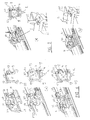
- FIG 8 several views are given on the longitudinal strip 4, wherein a recess 30 is cut on an interior longitudinal side 31 and/or an exterior longitudinal side 32 thereof. These recesses 30 cooperate with corresponding protrusions 33 on the legs 10,19 of the connecting device 6 in order to enhance the retention of the wiper blade 2.
- a recess 30 cooperates with corresponding protrusions 33 on the legs 10,19 of the connecting device 6 in order to enhance the retention of the wiper blade 2.
- one or two recess(es) 34 in said leg(s) 10,19 cooperate(s) with one or two upwardly extending protrusions 35 on the longitudinal strip 4.
- the retention of the wiper blade 2 may also be (whether or not the only) result of friction between legs 10, 19 or the connecting device 6 and the rubber of the wiper blade 2.
- FIG 10 corresponds to figures 4 and 5 , but now relating to a third embodiment, wherein corresponding parts have been designated with the same reference numerals, and wherein figures 10a through 10e chronologically show stepwise the mounting of a wiper blade 2 onto a connecting device 6 having a U-shaped cross-section with a base 11 and legs 10.
- the legs 10 are already in an open position to allow mounting of the wiper blade 2 between said legs 10, that is within the U-shaped cross-section, while leaving a space 18 open between a spoiler 9 of the wiper blade 2, the legs 10 and the base 11 of the connecting device 6 ( figure 10b ).
- said space 18 functions as a water channel as previously described regarding the first and second embodiments shown in figures 4 and 5 , as well as figures 6 and 7 , respectively.
- the legs 10 of the U-shaped cross-section are crimped or crushed in the direction of arrows of figures 10c and 10d .
- said legs 10 are forced to stay in the position of figure 10e , despite of any spring back phenomenon regarding said legs 10 when the crimping or crushing force is released ( figure 10e ).
- a cover (not shown) provided on said U-shaped cross-section can be used to force said legs 10 to stay in the position of figure 10e .
Priority Applications (8)
| Application Number | Priority Date | Filing Date | Title |
|---|---|---|---|
| ES09157195T ES2369052T3 (es) | 2009-04-02 | 2009-04-02 | Dispositivo limpiaparabrisas. |
| AT09157195T ATE514600T1 (de) | 2009-04-02 | 2009-04-02 | Scheibenwischvorrichtung |
| EP09157195A EP2236366B1 (en) | 2009-04-02 | 2009-04-02 | Windscreen wiper device |
| CN201080015182.XA CN102365193B (zh) | 2009-04-02 | 2010-04-01 | 风挡刮雨器装置 |
| JP2012502688A JP5571768B2 (ja) | 2009-04-02 | 2010-04-01 | フロントガラス用ワイパー装置 |
| KR1020117024103A KR101693392B1 (ko) | 2009-04-02 | 2010-04-01 | 유리창용 와이퍼 장치 |
| PCT/EP2010/054399 WO2010112579A1 (en) | 2009-04-02 | 2010-04-01 | Windscreen wiper device |
| US13/262,740 US9555774B2 (en) | 2009-04-02 | 2010-04-01 | Windscreen wiper device |
Applications Claiming Priority (1)
| Application Number | Priority Date | Filing Date | Title |
|---|---|---|---|
| EP09157195A EP2236366B1 (en) | 2009-04-02 | 2009-04-02 | Windscreen wiper device |
Publications (2)
| Publication Number | Publication Date |
|---|---|
| EP2236366A1 EP2236366A1 (en) | 2010-10-06 |
| EP2236366B1 true EP2236366B1 (en) | 2011-06-29 |
Family
ID=40935158
Family Applications (1)
| Application Number | Title | Priority Date | Filing Date |
|---|---|---|---|
| EP09157195A Active EP2236366B1 (en) | 2009-04-02 | 2009-04-02 | Windscreen wiper device |
Country Status (8)
| Country | Link |
|---|---|
| US (1) | US9555774B2 (es) |
| EP (1) | EP2236366B1 (es) |
| JP (1) | JP5571768B2 (es) |
| KR (1) | KR101693392B1 (es) |
| CN (1) | CN102365193B (es) |
| AT (1) | ATE514600T1 (es) |
| ES (1) | ES2369052T3 (es) |
| WO (1) | WO2010112579A1 (es) |
Cited By (6)
| Publication number | Priority date | Publication date | Assignee | Title |
|---|---|---|---|---|
| US8806700B2 (en) | 2011-07-29 | 2014-08-19 | Pylon Manufacturing Corporation | Wiper blade connector |
| CN103998300A (zh) * | 2011-12-16 | 2014-08-20 | 罗伯特·博世有限公司 | 具有至少两个通过收缩配合连接的刮水片单元的刮水装置 |
| US9108595B2 (en) | 2011-07-29 | 2015-08-18 | Pylon Manufacturing Corporation | Windshield wiper connector |
| US9457768B2 (en) | 2011-04-21 | 2016-10-04 | Pylon Manufacturing Corp. | Vortex damping wiper blade |
| US9505380B2 (en) | 2014-03-07 | 2016-11-29 | Pylon Manufacturing Corp. | Windshield wiper connector and assembly |
| USD777079S1 (en) | 2014-10-03 | 2017-01-24 | Pylon Manufacturing Corp. | Wiper blade frame |
Families Citing this family (26)
| Publication number | Priority date | Publication date | Assignee | Title |
|---|---|---|---|---|
| US20130227809A1 (en) | 2012-02-24 | 2013-09-05 | Pylon Manufacturing Corp. | Wiper blade |
| JP5795640B2 (ja) * | 2010-09-30 | 2015-10-14 | フェデラル−モグル エス.エー.Federal−Mogul.S.A. | フロントガラス用ワイパー装置 |
| DE102010062906A1 (de) * | 2010-12-13 | 2012-06-14 | Robert Bosch Gmbh | Wischblattvorrichtung |
| CN103347747B (zh) * | 2011-02-03 | 2017-05-17 | 联邦莫古尔股份有限公司 | 风挡雨刮器装置 |
| BR112013025393A2 (pt) * | 2011-04-07 | 2016-12-13 | Federal Mogul Sa | dispositivo limpador de para-brisa |
| KR101790384B1 (ko) * | 2011-04-13 | 2017-11-20 | 페더랄-모굴 에스.아. | 윈드스크린 와이퍼 장치 |
| JP6031509B2 (ja) * | 2011-04-13 | 2016-11-24 | フェデラル−モグル エス.エー.Federal−Mogul.S.A. | フロントガラス用ワイパー装置 |
| US9174609B2 (en) | 2011-04-21 | 2015-11-03 | Pylon Manufacturing Corp. | Wiper blade with cover |
| CA2843527C (en) | 2011-07-28 | 2018-11-27 | Pylon Manufacturing Corp. | Windshield wiper adapter, connector and assembly |
| CN103906660B (zh) * | 2011-08-31 | 2016-12-28 | 联邦莫古尔股份有限公司 | 挡风玻璃刮水器装置 |
| US9475465B2 (en) * | 2011-12-14 | 2016-10-25 | Federal-Mogul S.A. | Windscreen wiper device |
| US20130219649A1 (en) | 2012-02-24 | 2013-08-29 | Pylon Manufacturing Corp. | Wiper blade |
| US10829092B2 (en) | 2012-09-24 | 2020-11-10 | Pylon Manufacturing Corp. | Wiper blade with modular mounting base |
| US9511748B2 (en) | 2013-03-15 | 2016-12-06 | Illinois Tool Works Inc. | Universal connector for attachment of a windshield wiper blade with multiple types of windshield wiper arms |
| US9555775B2 (en) | 2013-03-15 | 2017-01-31 | Illinois Tool Works Inc. | Connectors and connector kit for attachment of a windshield wiper blade to multiple types of windshield wiper arms |
| US10166951B2 (en) | 2013-03-15 | 2019-01-01 | Pylon Manufacturing Corp. | Windshield wiper connector |
| US9616854B2 (en) * | 2013-04-25 | 2017-04-11 | Trico Products Corporation | Mounting assembly for wiper blade and wiper arm |
| PL3019373T3 (pl) * | 2013-07-09 | 2018-01-31 | Fed Mogul Sa | Wycieraczka szyby przedniej |
| USD727238S1 (en) | 2013-12-13 | 2015-04-21 | Illinois Tool Works Inc. | Cover used for windshield wiper connectors |
| KR101565825B1 (ko) * | 2014-03-11 | 2015-11-05 | 케이씨더블류 주식회사 | 플랫 와이퍼 블레이드 및 그 결합방법 |
| FR3043616B1 (fr) * | 2015-11-13 | 2017-12-15 | Valeo Systemes Dessuyage | Organe pour un systeme de connexion d’un balai d’essuie-glace a un bras d’entrainement |
| WO2017119853A1 (en) | 2016-01-06 | 2017-07-13 | Teklas Kaucuk Sanayi Ticaret A. S. | A connecting device for the vehicle wipers |
| US10150452B2 (en) | 2016-10-14 | 2018-12-11 | Federal-Mogul Motorparts Llc | Windscreen wiper device |
| CN107640129A (zh) * | 2017-10-27 | 2018-01-30 | 博世汽车部件(长春)有限公司 | 刮水器组件及其刮水片 |
| CN108238008B (zh) * | 2018-02-12 | 2024-04-26 | 博世汽车部件(长春)有限公司 | 刮水器及其刮水臂 |
| DE102019110084A1 (de) * | 2019-04-16 | 2020-10-22 | A. Raymond Et Cie | Windabweiser für eine Scheibenwischanlage eines Kraftwagens |
Family Cites Families (27)
| Publication number | Priority date | Publication date | Assignee | Title |
|---|---|---|---|---|
| GB524165A (en) * | 1939-01-23 | 1940-07-31 | William Edward O Shei | Improvements in or relating to windscreen wiper blades |
| IT990917B (it) * | 1972-07-07 | 1975-07-10 | Bosch Gmbh Robert | Impianto tergitore specie per pulire vetri di copertura di proiettori in veicoli a motore |
| DE19835065A1 (de) * | 1998-08-04 | 2000-02-10 | Bosch Gmbh Robert | Wischblatt für Scheiben von Kraftfahrzeugen |
| DE19906288A1 (de) * | 1999-02-15 | 2000-08-17 | Bosch Gmbh Robert | Vorrichtung zum gelenkigen Verbinden eines Wischblatts für Scheiben von Kraftfahrzeugen mit einem Wischerarm |
| DE19924662B4 (de) | 1999-05-28 | 2007-06-28 | Robert Bosch Gmbh | Wischvorrichtung für Scheiben von Kraftfahrzeugen |
| DE10033779A1 (de) * | 2000-07-12 | 2002-05-02 | Valeo Auto Electric Gmbh | Wischvorrichtung,insbesondere für Kraftfahrzeuge |
| DE10038993A1 (de) * | 2000-08-10 | 2002-03-07 | Valeo Auto Electric Gmbh | Wischvorrichtung, insbesondere für Kraftfahrzeuge |
| DE10341275A1 (de) * | 2003-09-08 | 2005-03-31 | Robert Bosch Gmbh | Wischblatt |
| DE10347637A1 (de) * | 2003-10-09 | 2005-05-12 | Bosch Gmbh Robert | Vorrichtung zum Verbinden eines Wischblatts mit einem Wischerarm sowie ein Wischblatt, einen Wischerarm und ein entsprechendes Verbindungsstück |
| DE10349637B4 (de) | 2003-10-24 | 2015-03-05 | Robert Bosch Gmbh | Gelenkverbindung |
| FR2868376B1 (fr) * | 2004-04-06 | 2006-06-02 | Valeo Systemes Dessuyage | Balai d'essuie-glace comportant une monture de support, une vertebre interne et un element de liaison |
| DE102004017941A1 (de) * | 2004-04-14 | 2005-11-03 | Robert Bosch Gmbh | Vorrichtung zum Verbinden eines Wischblatts mit einem Wischerarm |
| DE602004010644T2 (de) * | 2004-08-03 | 2008-11-27 | Federal-Mogul S.A. | Scheibenwischervorrichtung |
| BRMU8402004U (pt) * | 2004-08-17 | 2004-12-28 | Dyna Electromecanica | Disposição introduzida em palheta |
| US20060265830A1 (en) * | 2005-02-14 | 2006-11-30 | Tenneco Automotive Operating Company Inc. | Encapsulated beam with anti-rotation system |
| CN101233026A (zh) * | 2005-07-28 | 2008-07-30 | 坦尼科汽车操作有限公司 | 具有轴向平移阻止系统的挡风玻璃擦拭片组件 |
| US7350259B2 (en) * | 2005-07-28 | 2008-04-01 | Tenneco Automotive Operating Company Inc. | Relative axial translation prevention system for wiper blade assemblies |
| FR2893896B1 (fr) * | 2005-11-30 | 2008-02-01 | Valeo Systemes Dessuyage | Support de montage d'un balai d'essuie-glace sur un bras d'entrainement realise en tole pliee |
| FR2894544B1 (fr) * | 2005-12-14 | 2009-07-03 | Valeo Systemes Dessuyage | Balai d'essuie-glace comportant une monture de support, une vertebre interne et un element de liaison |
| FR2894917B1 (fr) * | 2005-12-21 | 2009-07-03 | Valeo Systemes Dessuyage | Dispositif de fixation et connexion centrale de balai d'essuie-glace. |
| DE102005062463A1 (de) * | 2005-12-27 | 2007-06-28 | Robert Bosch Gmbh | Anschlusselement |
| ES2337172T3 (es) * | 2006-04-21 | 2010-04-21 | Federal-Mogul S.A. | Un dispositivo de limpiaparabrisas. |
| DE602006008767D1 (de) * | 2006-07-04 | 2009-10-08 | Federal Mogul Sa | Scheibenwischervorrichtung |
| DE602006008768D1 (de) * | 2006-07-06 | 2009-10-08 | Federal Mogul Sa | Scheibenwischervorrichtung |
| US7721382B2 (en) * | 2007-04-23 | 2010-05-25 | Malone Randolph W | Frameless, heated wiper assembly and system utilizing same |
| WO2008148265A1 (fr) * | 2007-06-07 | 2008-12-11 | Qinghuai Shen | Nouveau balai d'essuie-glace |
| EP2008891B1 (en) * | 2007-06-27 | 2011-02-16 | Federal-Mogul S.A. | Windscreen wiper device |
-
2009
- 2009-04-02 AT AT09157195T patent/ATE514600T1/de not_active IP Right Cessation
- 2009-04-02 ES ES09157195T patent/ES2369052T3/es active Active
- 2009-04-02 EP EP09157195A patent/EP2236366B1/en active Active
-
2010
- 2010-04-01 KR KR1020117024103A patent/KR101693392B1/ko active IP Right Grant
- 2010-04-01 CN CN201080015182.XA patent/CN102365193B/zh active Active
- 2010-04-01 JP JP2012502688A patent/JP5571768B2/ja not_active Expired - Fee Related
- 2010-04-01 US US13/262,740 patent/US9555774B2/en active Active
- 2010-04-01 WO PCT/EP2010/054399 patent/WO2010112579A1/en active Application Filing
Cited By (6)
| Publication number | Priority date | Publication date | Assignee | Title |
|---|---|---|---|---|
| US9457768B2 (en) | 2011-04-21 | 2016-10-04 | Pylon Manufacturing Corp. | Vortex damping wiper blade |
| US8806700B2 (en) | 2011-07-29 | 2014-08-19 | Pylon Manufacturing Corporation | Wiper blade connector |
| US9108595B2 (en) | 2011-07-29 | 2015-08-18 | Pylon Manufacturing Corporation | Windshield wiper connector |
| CN103998300A (zh) * | 2011-12-16 | 2014-08-20 | 罗伯特·博世有限公司 | 具有至少两个通过收缩配合连接的刮水片单元的刮水装置 |
| US9505380B2 (en) | 2014-03-07 | 2016-11-29 | Pylon Manufacturing Corp. | Windshield wiper connector and assembly |
| USD777079S1 (en) | 2014-10-03 | 2017-01-24 | Pylon Manufacturing Corp. | Wiper blade frame |
Also Published As
| Publication number | Publication date |
|---|---|
| US9555774B2 (en) | 2017-01-31 |
| KR101693392B1 (ko) | 2017-01-17 |
| CN102365193A (zh) | 2012-02-29 |
| JP2012522678A (ja) | 2012-09-27 |
| CN102365193B (zh) | 2014-12-10 |
| JP5571768B2 (ja) | 2014-08-13 |
| EP2236366A1 (en) | 2010-10-06 |
| ES2369052T3 (es) | 2011-11-24 |
| US20120110772A1 (en) | 2012-05-10 |
| ATE514600T1 (de) | 2011-07-15 |
| WO2010112579A1 (en) | 2010-10-07 |
| KR20120009450A (ko) | 2012-01-31 |
Similar Documents
| Publication | Publication Date | Title |
|---|---|---|
| EP2236366B1 (en) | Windscreen wiper device | |
| EP2103490B1 (en) | Windscreen wiper device | |
| EP2697102B1 (en) | Windscreen wiper device | |
| EP2697100B1 (en) | Windscreen wiper device | |
| US10576938B2 (en) | Windscreen wiper device | |
| EP2726331B1 (en) | Method for manufacturing a windscreen wiper device | |
| US9925958B2 (en) | Windscreen wiper device | |
| EP2621772B1 (en) | Windscreen wiper device | |
| EP2864162B1 (en) | Windscreen wiper device | |
| EP2585344B1 (en) | A windscreen wiper device | |
| WO2017097353A1 (en) | Windscreen wiper device |
Legal Events
| Date | Code | Title | Description |
|---|---|---|---|
| PUAI | Public reference made under article 153(3) epc to a published international application that has entered the european phase |
Free format text: ORIGINAL CODE: 0009012 |
|
| 17P | Request for examination filed |
Effective date: 20090916 |
|
| AK | Designated contracting states |
Kind code of ref document: A1 Designated state(s): AT BE BG CH CY CZ DE DK EE ES FI FR GB GR HR HU IE IS IT LI LT LU LV MC MK MT NL NO PL PT RO SE SI SK TR |
|
| AX | Request for extension of the european patent |
Extension state: AL BA RS |
|
| GRAP | Despatch of communication of intention to grant a patent |
Free format text: ORIGINAL CODE: EPIDOSNIGR1 |
|
| GRAS | Grant fee paid |
Free format text: ORIGINAL CODE: EPIDOSNIGR3 |
|
| GRAA | (expected) grant |
Free format text: ORIGINAL CODE: 0009210 |
|
| AK | Designated contracting states |
Kind code of ref document: B1 Designated state(s): AT BE BG CH CY CZ DE DK EE ES FI FR GB GR HR HU IE IS IT LI LT LU LV MC MK MT NL NO PL PT RO SE SI SK TR |
|
| REG | Reference to a national code |
Ref country code: GB Ref legal event code: FG4D |
|
| REG | Reference to a national code |
Ref country code: CH Ref legal event code: EP |
|
| REG | Reference to a national code |
Ref country code: IE Ref legal event code: FG4D |
|
| REG | Reference to a national code |
Ref country code: DE Ref legal event code: R096 Ref document number: 602009001657 Country of ref document: DE Effective date: 20110908 |
|
| REG | Reference to a national code |
Ref country code: NL Ref legal event code: VDEP Effective date: 20110629 |
|
| PG25 | Lapsed in a contracting state [announced via postgrant information from national office to epo] |
Ref country code: NO Free format text: LAPSE BECAUSE OF FAILURE TO SUBMIT A TRANSLATION OF THE DESCRIPTION OR TO PAY THE FEE WITHIN THE PRESCRIBED TIME-LIMIT Effective date: 20110929 Ref country code: SE Free format text: LAPSE BECAUSE OF FAILURE TO SUBMIT A TRANSLATION OF THE DESCRIPTION OR TO PAY THE FEE WITHIN THE PRESCRIBED TIME-LIMIT Effective date: 20110629 Ref country code: LT Free format text: LAPSE BECAUSE OF FAILURE TO SUBMIT A TRANSLATION OF THE DESCRIPTION OR TO PAY THE FEE WITHIN THE PRESCRIBED TIME-LIMIT Effective date: 20110629 Ref country code: HR Free format text: LAPSE BECAUSE OF FAILURE TO SUBMIT A TRANSLATION OF THE DESCRIPTION OR TO PAY THE FEE WITHIN THE PRESCRIBED TIME-LIMIT Effective date: 20110629 |
|
| REG | Reference to a national code |
Ref country code: ES Ref legal event code: FG2A Ref document number: 2369052 Country of ref document: ES Kind code of ref document: T3 Effective date: 20111124 |
|
| PG25 | Lapsed in a contracting state [announced via postgrant information from national office to epo] |
Ref country code: SI Free format text: LAPSE BECAUSE OF FAILURE TO SUBMIT A TRANSLATION OF THE DESCRIPTION OR TO PAY THE FEE WITHIN THE PRESCRIBED TIME-LIMIT Effective date: 20110629 Ref country code: LV Free format text: LAPSE BECAUSE OF FAILURE TO SUBMIT A TRANSLATION OF THE DESCRIPTION OR TO PAY THE FEE WITHIN THE PRESCRIBED TIME-LIMIT Effective date: 20110629 Ref country code: AT Free format text: LAPSE BECAUSE OF FAILURE TO SUBMIT A TRANSLATION OF THE DESCRIPTION OR TO PAY THE FEE WITHIN THE PRESCRIBED TIME-LIMIT Effective date: 20110629 Ref country code: FI Free format text: LAPSE BECAUSE OF FAILURE TO SUBMIT A TRANSLATION OF THE DESCRIPTION OR TO PAY THE FEE WITHIN THE PRESCRIBED TIME-LIMIT Effective date: 20110629 Ref country code: GR Free format text: LAPSE BECAUSE OF FAILURE TO SUBMIT A TRANSLATION OF THE DESCRIPTION OR TO PAY THE FEE WITHIN THE PRESCRIBED TIME-LIMIT Effective date: 20110930 |
|
| PG25 | Lapsed in a contracting state [announced via postgrant information from national office to epo] |
Ref country code: IS Free format text: LAPSE BECAUSE OF FAILURE TO SUBMIT A TRANSLATION OF THE DESCRIPTION OR TO PAY THE FEE WITHIN THE PRESCRIBED TIME-LIMIT Effective date: 20111029 Ref country code: NL Free format text: LAPSE BECAUSE OF FAILURE TO SUBMIT A TRANSLATION OF THE DESCRIPTION OR TO PAY THE FEE WITHIN THE PRESCRIBED TIME-LIMIT Effective date: 20110629 Ref country code: EE Free format text: LAPSE BECAUSE OF FAILURE TO SUBMIT A TRANSLATION OF THE DESCRIPTION OR TO PAY THE FEE WITHIN THE PRESCRIBED TIME-LIMIT Effective date: 20110629 Ref country code: PT Free format text: LAPSE BECAUSE OF FAILURE TO SUBMIT A TRANSLATION OF THE DESCRIPTION OR TO PAY THE FEE WITHIN THE PRESCRIBED TIME-LIMIT Effective date: 20111031 Ref country code: CZ Free format text: LAPSE BECAUSE OF FAILURE TO SUBMIT A TRANSLATION OF THE DESCRIPTION OR TO PAY THE FEE WITHIN THE PRESCRIBED TIME-LIMIT Effective date: 20110629 |
|
| PG25 | Lapsed in a contracting state [announced via postgrant information from national office to epo] |
Ref country code: SK Free format text: LAPSE BECAUSE OF FAILURE TO SUBMIT A TRANSLATION OF THE DESCRIPTION OR TO PAY THE FEE WITHIN THE PRESCRIBED TIME-LIMIT Effective date: 20110629 Ref country code: CY Free format text: LAPSE BECAUSE OF FAILURE TO SUBMIT A TRANSLATION OF THE DESCRIPTION OR TO PAY THE FEE WITHIN THE PRESCRIBED TIME-LIMIT Effective date: 20110629 Ref country code: PL Free format text: LAPSE BECAUSE OF FAILURE TO SUBMIT A TRANSLATION OF THE DESCRIPTION OR TO PAY THE FEE WITHIN THE PRESCRIBED TIME-LIMIT Effective date: 20110629 |
|
| PLBE | No opposition filed within time limit |
Free format text: ORIGINAL CODE: 0009261 |
|
| STAA | Information on the status of an ep patent application or granted ep patent |
Free format text: STATUS: NO OPPOSITION FILED WITHIN TIME LIMIT |
|
| 26N | No opposition filed |
Effective date: 20120330 |
|
| PG25 | Lapsed in a contracting state [announced via postgrant information from national office to epo] |
Ref country code: DK Free format text: LAPSE BECAUSE OF FAILURE TO SUBMIT A TRANSLATION OF THE DESCRIPTION OR TO PAY THE FEE WITHIN THE PRESCRIBED TIME-LIMIT Effective date: 20110629 |
|
| REG | Reference to a national code |
Ref country code: DE Ref legal event code: R097 Ref document number: 602009001657 Country of ref document: DE Effective date: 20120330 |
|
| PG25 | Lapsed in a contracting state [announced via postgrant information from national office to epo] |
Ref country code: MC Free format text: LAPSE BECAUSE OF NON-PAYMENT OF DUE FEES Effective date: 20120430 |
|
| REG | Reference to a national code |
Ref country code: IE Ref legal event code: MM4A |
|
| PG25 | Lapsed in a contracting state [announced via postgrant information from national office to epo] |
Ref country code: IE Free format text: LAPSE BECAUSE OF NON-PAYMENT OF DUE FEES Effective date: 20120402 |
|
| PG25 | Lapsed in a contracting state [announced via postgrant information from national office to epo] |
Ref country code: MK Free format text: LAPSE BECAUSE OF FAILURE TO SUBMIT A TRANSLATION OF THE DESCRIPTION OR TO PAY THE FEE WITHIN THE PRESCRIBED TIME-LIMIT Effective date: 20110629 |
|
| PG25 | Lapsed in a contracting state [announced via postgrant information from national office to epo] |
Ref country code: BG Free format text: LAPSE BECAUSE OF FAILURE TO SUBMIT A TRANSLATION OF THE DESCRIPTION OR TO PAY THE FEE WITHIN THE PRESCRIBED TIME-LIMIT Effective date: 20110929 |
|
| PG25 | Lapsed in a contracting state [announced via postgrant information from national office to epo] |
Ref country code: MT Free format text: LAPSE BECAUSE OF FAILURE TO SUBMIT A TRANSLATION OF THE DESCRIPTION OR TO PAY THE FEE WITHIN THE PRESCRIBED TIME-LIMIT Effective date: 20110629 |
|
| REG | Reference to a national code |
Ref country code: CH Ref legal event code: PL |
|
| GBPC | Gb: european patent ceased through non-payment of renewal fee |
Effective date: 20130402 |
|
| PG25 | Lapsed in a contracting state [announced via postgrant information from national office to epo] |
Ref country code: CH Free format text: LAPSE BECAUSE OF NON-PAYMENT OF DUE FEES Effective date: 20130430 Ref country code: GB Free format text: LAPSE BECAUSE OF NON-PAYMENT OF DUE FEES Effective date: 20130402 Ref country code: LI Free format text: LAPSE BECAUSE OF NON-PAYMENT OF DUE FEES Effective date: 20130430 |
|
| PG25 | Lapsed in a contracting state [announced via postgrant information from national office to epo] |
Ref country code: TR Free format text: LAPSE BECAUSE OF FAILURE TO SUBMIT A TRANSLATION OF THE DESCRIPTION OR TO PAY THE FEE WITHIN THE PRESCRIBED TIME-LIMIT Effective date: 20110629 |
|
| PG25 | Lapsed in a contracting state [announced via postgrant information from national office to epo] |
Ref country code: LU Free format text: LAPSE BECAUSE OF NON-PAYMENT OF DUE FEES Effective date: 20120402 |
|
| PG25 | Lapsed in a contracting state [announced via postgrant information from national office to epo] |
Ref country code: HU Free format text: LAPSE BECAUSE OF FAILURE TO SUBMIT A TRANSLATION OF THE DESCRIPTION OR TO PAY THE FEE WITHIN THE PRESCRIBED TIME-LIMIT Effective date: 20090402 |
|
| REG | Reference to a national code |
Ref country code: FR Ref legal event code: PLFP Year of fee payment: 8 |
|
| PGFP | Annual fee paid to national office [announced via postgrant information from national office to epo] |
Ref country code: ES Payment date: 20160406 Year of fee payment: 8 |
|
| REG | Reference to a national code |
Ref country code: FR Ref legal event code: PLFP Year of fee payment: 9 |
|
| REG | Reference to a national code |
Ref country code: FR Ref legal event code: PLFP Year of fee payment: 10 |
|
| REG | Reference to a national code |
Ref country code: ES Ref legal event code: FD2A Effective date: 20180706 |
|
| PG25 | Lapsed in a contracting state [announced via postgrant information from national office to epo] |
Ref country code: ES Free format text: LAPSE BECAUSE OF NON-PAYMENT OF DUE FEES Effective date: 20170403 |
|
| PGFP | Annual fee paid to national office [announced via postgrant information from national office to epo] |
Ref country code: BE Payment date: 20200316 Year of fee payment: 12 |
|
| PGFP | Annual fee paid to national office [announced via postgrant information from national office to epo] |
Ref country code: FR Payment date: 20200312 Year of fee payment: 12 |
|
| PGFP | Annual fee paid to national office [announced via postgrant information from national office to epo] |
Ref country code: IT Payment date: 20200312 Year of fee payment: 12 |
|
| REG | Reference to a national code |
Ref country code: BE Ref legal event code: MM Effective date: 20210430 |
|
| PG25 | Lapsed in a contracting state [announced via postgrant information from national office to epo] |
Ref country code: FR Free format text: LAPSE BECAUSE OF NON-PAYMENT OF DUE FEES Effective date: 20210430 |
|
| PG25 | Lapsed in a contracting state [announced via postgrant information from national office to epo] |
Ref country code: BE Free format text: LAPSE BECAUSE OF NON-PAYMENT OF DUE FEES Effective date: 20210430 |
|
| PG25 | Lapsed in a contracting state [announced via postgrant information from national office to epo] |
Ref country code: IT Free format text: LAPSE BECAUSE OF NON-PAYMENT OF DUE FEES Effective date: 20200402 |
|
| PGFP | Annual fee paid to national office [announced via postgrant information from national office to epo] |
Ref country code: DE Payment date: 20230427 Year of fee payment: 15 |