EP2236244B1 - Fertige ophthalmische Linsen und entsprechende Verfahren - Google Patents
Fertige ophthalmische Linsen und entsprechende Verfahren Download PDFInfo
- Publication number
- EP2236244B1 EP2236244B1 EP09380092.8A EP09380092A EP2236244B1 EP 2236244 B1 EP2236244 B1 EP 2236244B1 EP 09380092 A EP09380092 A EP 09380092A EP 2236244 B1 EP2236244 B1 EP 2236244B1
- Authority
- EP
- European Patent Office
- Prior art keywords
- lens
- perimeter
- area
- useful
- central
- Prior art date
- Legal status (The legal status is an assumption and is not a legal conclusion. Google has not performed a legal analysis and makes no representation as to the accuracy of the status listed.)
- Active
Links
Images



Classifications
-
- G—PHYSICS
- G02—OPTICS
- G02C—SPECTACLES; SUNGLASSES OR GOGGLES INSOFAR AS THEY HAVE THE SAME FEATURES AS SPECTACLES; CONTACT LENSES
- G02C7/00—Optical parts
- G02C7/02—Lenses; Lens systems ; Methods of designing lenses
-
- B—PERFORMING OPERATIONS; TRANSPORTING
- B24—GRINDING; POLISHING
- B24B—MACHINES, DEVICES, OR PROCESSES FOR GRINDING OR POLISHING; DRESSING OR CONDITIONING OF ABRADING SURFACES; FEEDING OF GRINDING, POLISHING, OR LAPPING AGENTS
- B24B13/00—Machines or devices designed for grinding or polishing optical surfaces on lenses or surfaces of similar shape on other work; Accessories therefor
- B24B13/06—Machines or devices designed for grinding or polishing optical surfaces on lenses or surfaces of similar shape on other work; Accessories therefor grinding of lenses, the tool or work being controlled by information-carrying means, e.g. patterns, punched tapes, magnetic tapes
-
- B—PERFORMING OPERATIONS; TRANSPORTING
- B24—GRINDING; POLISHING
- B24B—MACHINES, DEVICES, OR PROCESSES FOR GRINDING OR POLISHING; DRESSING OR CONDITIONING OF ABRADING SURFACES; FEEDING OF GRINDING, POLISHING, OR LAPPING AGENTS
- B24B49/00—Measuring or gauging equipment for controlling the feed movement of the grinding tool or work; Arrangements of indicating or measuring equipment, e.g. for indicating the start of the grinding operation
-
- B—PERFORMING OPERATIONS; TRANSPORTING
- B24—GRINDING; POLISHING
- B24B—MACHINES, DEVICES, OR PROCESSES FOR GRINDING OR POLISHING; DRESSING OR CONDITIONING OF ABRADING SURFACES; FEEDING OF GRINDING, POLISHING, OR LAPPING AGENTS
- B24B9/00—Machines or devices designed for grinding edges or bevels on work or for removing burrs; Accessories therefor
- B24B9/02—Machines or devices designed for grinding edges or bevels on work or for removing burrs; Accessories therefor characterised by a special design with respect to properties of materials specific to articles to be ground
- B24B9/06—Machines or devices designed for grinding edges or bevels on work or for removing burrs; Accessories therefor characterised by a special design with respect to properties of materials specific to articles to be ground of non-metallic inorganic material, e.g. stone, ceramics, porcelain
- B24B9/08—Machines or devices designed for grinding edges or bevels on work or for removing burrs; Accessories therefor characterised by a special design with respect to properties of materials specific to articles to be ground of non-metallic inorganic material, e.g. stone, ceramics, porcelain of glass
- B24B9/14—Machines or devices designed for grinding edges or bevels on work or for removing burrs; Accessories therefor characterised by a special design with respect to properties of materials specific to articles to be ground of non-metallic inorganic material, e.g. stone, ceramics, porcelain of glass of optical work, e.g. lenses, prisms
Definitions
- the invention relates to a method of machining an ophthalmic lens having one concave face and one convex face and an outer perimeter, where the outer perimeter has a thickness within a pre-established range.
- the invention also relates to a method of manufacturing a bevelled finished ophthalmic lens.
- the invention also relates to a finished ophthalmic lens having one concave face and one convex face and an outer perimeter, where the outer perimeter has a thickness within a pre-established range.
- ophthalmic lenses are made from semifinished lens blanks.
- Semifinished lens blanks usually have a circular outer perimeter and comprise one convex face (away from the user's eye) and one concave face (near the user's eye).
- Semifinished lens blanks are produced by combining particular concave faces and particular convex faces.
- an "approximate" semifinished lens blank is used and one of its faces is machined so that the machined lens, called the finished lens, fulfils the pre-established prescription.
- Finished lenses are usually large enough for most conventional ophthalmic lenses to "fit" inside them. This is done by means of a bevelling operation, where all the excess material from the finished lens is removed, until said bevelled finished lens is obtained.
- the lenses can be grouped into two large families.
- negative lenses are those where the curvature radius of the concave surface is less than the curvature radius of the convex surface. Therefore, negative lenses have a thickness that increases as we move away from the optical axis.
- positive lenses are those where the curvature radius of the concave surface is greater than the curvature radius of the convex surface, or it can even be an opposite sign. In this second case, the thickness of the lens decreases as we move away from the optical eye.
- progressive lenses can have a negative area and a positive area, whereby the thickness of the lens varies in a complex way from one point to another on the same lens.
- the thickness of the outer perimeter of the finished lens By machining the semifinished lens blank so that it fulfils a particular pre-established prescription, there may be problems with the thickness of the outer perimeter of the finished lens. In some cases, this thickness can end up being very big, with the subsequent problem of the lack of material if the thickness of the semifinished lens blank before machining was not sufficient. In other cases, it is possible that the thickness may be excessively fine, and even that it may be null or negative, which means that the perimeter of the finished lens, once it has been machined, is no longer circular, and instead has "recesses". All this hinders the subsequent handling of the finished lens, because conventional methods and machinery have been designed to process finished lenses with a regular outer perimeter.
- a stage known as the pre-calibrating stage is carried out for this purpose, wherein, by knowing beforehand the perimeter of the particular frame for which the lens is intended, the surface to be machined (which is on one of said concave or convex faces) is positioned with respect to the other face, so that the thickness of the ophthalmic lens is minimised.
- this pre-calibration stage is conditioned by the problems mentioned in the paragraph above.
- Document US 5.545.075 discloses a process, as per the preamble of claim 1, for the production of an edged ophthalmic lens wherein an ophthalmic lens which initially is finished on one side and not yet edged according to a prescribed disk shape, i.e. a so-called blank having only one finished effective surface, is produced and the so-called prescription surface is produced in another manufacturing step, if need be, including optimization of the critical thickness.
- the invented process is distinguished by the combination of the following steps: the prescribed disk shape is stored as a set of data, the position of the second surface (prescription surface) is computed, if need be, including the minimization of the critical thickness from the stored set of data of the prescribed disk shape and the contour of the already finished surface of said blank, subsequently the prescription surface is produced with simultaneous or previous preliminary edging of the blank according to the prescribed disk shape, following production of the prescription surface, the lens is edged, facetted and its perimeter polished in a gripping means utilizing the stored set of data.
- US 5.545.075 discloses a lens as per the preamble of claim 7.
- the aim of the invention is to overcome these drawbacks, and propose a new method for pre-calibrating and machining ophthalmic lenses. This purpose is achieved by means of a method as per claim 1.
- the pre-calibration can be performed so as to optimise the thickness of the definitive ophthalmic lens; in other words, the one that will be mounted in the frame after the bevelling operation.
- the pre-calibration should only respect the conditions of the thickness of the lens on its inner point and on the perimeter of the frame, without being influenced by possible conditioning factors arising from the semifinished lens blank, which in the end will not be part of the definitive bevelled lens.
- a new surface extends from the useful perimeter, i.e.: the transition surface, which is intended to be a joining element between the useful perimeter and the outer perimeter so that the necessary thicknesses are respected.
- the new method allows "double optimization”: on the one hand, the thickness of the lens is optimised (i.e. the definitive lens, after bevelling ) and, on the other hand, the thickness and geometry of the finished lens is optimised, so that it is possible to handle and process it adequately, while considering the frame on which the lens is intended to be mounted.
- an outer perimeter is obtained which , apart from maintaining its thickness within the pre-established range, minimises the curvature variation in an angular direction.
- the thickness of the outer perimeter is preferably constant, but this cannot be obtained in every case or, at least it is not advisable to force it because other advantageous surface characteristics are lost. Therefore, the only input noted is a pre-established thickness range, where the maximum value is preferably the thickness value of the ophthalmic lens predetermined before machining, and the minimum value is preferably 0.3 mm. Values below this minimum value cause problems in the subsequent handling and processing of the lens, for example, with polishing cloths. However, as mentioned previously, it is advantageous to minimise the curvature variations in the angular direction; in other words, the thickness variations of the outer perimeter.
- stage [d] specifies the minimum curvature radius of the cutting tools that are used to machine the transition surface, and defines the transition surface so that it has a main minimum curvature radius on all points, which is greater than the minimum curvature radius of the cutting tools.
- the cutting tool Given that it is necessary for the cutting tool to have a smaller curvature radius than the minimum curvature of the surface that is being machined, it is advantageous to already bear this in mind during the design stage of the transition surface.
- the method according to the invention can be used advantageously both when the central area is a positive lens (as the thickness of the central area can be minimised, only making sure that the thickness on the transition perimeter fulfils particular minimum thickness requirements, and without worrying about the outer perimeter of the finished lens) and when the central area is a negative lens (without worrying about the outer perimeter of the finished lens which, in cases of severe short-sightedness, could end up having to be much greater than the outer thickness of the original semifinished lens blank).
- the method is particularly interesting in the case of progressive lens, where positive and negative areas can coexist.
- the invention is also aimed at a method of manufacturing a finished, bevelled ophthalmic lens characterized in that it comprises a method of machining a lens according to the invention and, additionally, it comprises a bevelling stage along the useful perimeter, thus obtaining a bevelled lens, so that the bevelled lens is shaped completely from the central useful area.
- the aim of the invention is also a finished ophthalmic lens having one concave face and one convex face and an outer perimeter, where the outer perimeter has a thickness within a pre-established range, characterized in that : [a] it has a central useful area wherein the concave face and the convex face are such that they fulfil a particular, pre-established ophthalmic prescription and where one of said concave and convex faces defines a machined surface, where the central useful area has a useful perimeter that coincides with the perimeter of a particular, pre-established frame, and [b] it has an outer transition area that joins the useful perimeter of the central useful area to the outer perimeter, where the transition area comprises a transition surface that extends as a continuation of the machined surface as far as the outer perimeter, and where the transition surface is continuous and its derivative is continuous on all points, including the joining line between the transition surface and the machined surface.
- this finished ophthalmic lens has, on the one hand, a central useful area from which an ophthalmic lens with
- the invention is also used advantageously both when the central area is a positive lens and when the central area is a negative lens. Also, as mentioned before, it is also advantageous when the lens is a progressive lens.
- Figure 1 shows a finished ophthalmic lens according to the invention.
- the ophthalmic lens has an outer perimeter 1, normally of a standardised value, such as for example 65 mm in diameter.
- an outer perimeter 3 defined by a useful perimeter 5 that coincides with the perimeter of a particular, pre-established frame; in other words, a frame that has been chosen by the user and in which the lens that is being manufactured has to be housed.
- a transition area 7 which is the area that will be removed during the bevelling operation. Therefore, transition area 7 is a non-useful area from the optical point of view.
- the shape of the frame determines a central useful area 3 of the definitive lens that fulfils the optical properties the lens must have in order to adequately correct the user's vision.
- central useful area 3 fulfils a particular, pre-established ophthalmic prescription
- a progressive lens has an area of far vision, an area of near vision and an intermediate passage that strictly fulfil the user's needs, and a wider area where the appearance of aberrations is inevitable (particularly, astigmatism).
- the lens, overall, fulfils a particular ophthalmic prescription corresponds to said prescription, or is suitable for said prescription.
- the area of the finished lens that remains outside the contour of the frame becomes an optically non-useful area, where a surface will be defined that will not have particular optical properties, but will have geometrical properties, which will make it possible to join the edge of central useful area 3 defined by the frame (in other words, useful perimeter 5) to the edge of the finished lens, that is, outer perimeter 1.
- the semifinished ophthalmic lens blank has one convex face and one concave face (which is the face that remains nearest the user's eye).
- the concave face is the one with the surface to be machined, although the invention could be applied conceptually in the same way if the surface to be machined were the convex face.
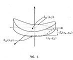
- the lens (see Figure 3 ) is determined by two surfaces, the concave one and the convex one.
- This concave surface is the one that has been called the surface to be machined.
- This thickness does not have to be the thickness of the predefined edge, as it can be modified.
- the transition surface, T T ( x,y ) has to fulfil particular continuity requirements so that the numeric control machine can cut the lens.
- the transition surface fulfils at least one continuity C 1 , in other words, that it is continuous and also that its first derivative is continuous.
- the thickness of the outer perimeter of the finished lens can be fixed in several ways. Preferably it is limited within “absolute" maximum and minimum values for practical reasons. Moreover, it is recommendable that the maximum value is not greater than the thickness value of the original semifinished lens blank because, otherwise, there would be the problem of the lack of material for obtaining the desired thickness. Furthermore, it is recommendable that the lens has a certain thickness so that it can be handled subsequently. This minimum thickness is preferably greater or equivalent to 0.3 mm, because if the thickness is less there tend to be problems with the polishing cloths. Apart from these "absolute" maximum and minimum values, in each case, it may be recommendable to set other maximum and minimum values according to other conditions. So, generally, it is recommendable that the thickness be as constant as possible. Moreover, as will be seen later, the method of calculating the transition surface and the method of machining the transition surface (particularly the radii of the machining tools) can impose other limits.
- Figure 4 shows a cross-section of a lens according to the invention, in particular, a negative lens.
- the two-dimensional profile of the lens can be seen, for a fixed "y" co-ordinate, where the pre-calibrating surfaces can be observed.
- the convex face of the lens corresponds to the surface of the semifinished lens blank.
- the concave face of the lens we can see the surface corresponding to central useful area 3 (in other words, the surface to be machined) up to the limit co-ordinate of the frame and afterwards the transition surface up to the edge of the finished lens.
- Figure 5 is equivalent to Figure 4 , but shows a positive lens.
- Figure 6 shows schematically a semifinished lens blank with useful perimeter 5 and outer perimeter 1, where the dotted line shows the contour of the points of contact 11.
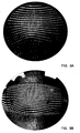
- Figures 8A and 8B show some photographs that feature, respectively, a progressive finished conventional ophthalmic lens and a progressive finished ophthalmic lens according to the invention, arranged on a grid. In the distortion produced on the grid, the differences between both finished lenses can be clearly seen. In particular, in the finished lens according to the invention, the existence of two areas (the central useful area and the transition area) can be seen, and the "thumbprint" of the useful perimeter is shown, that is, of the perimeter of the frame wherein it is envisaged to mount the lens once it is bevelled.
Landscapes
- Engineering & Computer Science (AREA)
- Mechanical Engineering (AREA)
- Physics & Mathematics (AREA)
- Health & Medical Sciences (AREA)
- Ophthalmology & Optometry (AREA)
- Chemical & Material Sciences (AREA)
- Ceramic Engineering (AREA)
- Inorganic Chemistry (AREA)
- General Physics & Mathematics (AREA)
- Optics & Photonics (AREA)
- General Health & Medical Sciences (AREA)
- Eyeglasses (AREA)
- Grinding And Polishing Of Tertiary Curved Surfaces And Surfaces With Complex Shapes (AREA)
Claims (10)
- Verfahren zur Bearbeitung einer ophthalmischen Linse mit einer konkaven Seite und einer konvexen Seite und einem Außenumfang (1), wobei der Außenumfang (1) eine Dicke in einem vorgegebenen Bereich aufweist, wobei das Verfahren die folgenden Schritte umfasst:[a] Definieren eines zentralen nutzbaren Bereichs (3) mit einem nutzbaren Umfang (5), der mit dem Umfang einer vorgegebenen speziellen Fassung zusammenfällt,[b] Definieren einer zu bearbeitenden Oberfläche auf der konvaven oder konvexen Seite so, dass die konkave und die konvexe Seite zusammen derart ausgebildet sind, dass sie eine spezielle vorgeschriebene ophthalmische Vorgabe in dem zentralen nutzbaren Bereich (3) erfüllen,[c] Positionieren der zu bearbeitenden Oberfläche, die auf der konvaven oder konvexen Seite angeordnet ist, zur anderen konvaven oder konvexen Seite so, dass die zu bearbeitende Oberfläche und ihre Position zur anderen konvaven oder konvexen Seite die Dicke der Linse entlang des nutzbaren Umfangs (5) in dem zentralen nutzbaren Bereich (3) bestimmt,[e] Bearbeiten der zu bearbeitenden Oberfläche,
gekennzeichnet durch[d] Definieren eines Übergangsbereichs (7) mit einer Übergangsfläche, die sich zwischen dem nutzbaren Umfang (5) des zentralen nutzbaren Bereichs (3) und dem Außenumfang (1) erstreckt, wobei die Übergangsfläche sich wie eine Fortsetzung der zu bearbeitenden Oberfläche bis zu dem Außenumfang (1) erstreckt, und wobei die Übergangsfläche kontinuierlich ausgebildet ist und ihre Ableitung an allen Punkten kontinuierlich ist, einschließlich der Verbindungslinie zwischen der Übergangsfläche und der zu bearbeitenden Oberfläche, gefolgt von Schritt [e]. - Verfahren nach Anspruch 1, dadurch gekennzeichnet, dass im Schritt [d] ein Außenumfang (1) erhalten wird, der, außer einer Bearbeitung seiner Dicke in dem vorgegebenen Bereich, die Krümmungsabweichung in einer Winkelrichtung minimiert.
- Verfahren nach Anspruch 1 oder 2, dadurch gekennzeichnet, dass im Schritt [d] der minimale Krümmungsradius der Schneidwerkzeuge, die zum Bearbeiten der Übergangsfläche verwendet werden, spezifiziert wird und die Übergangsfläche so definiert wird, dass sie an allen ihren Punkten einen minimalen Hauptkrümmungsradius aufweist, der größer ist als der minimale Krümmungsradius der Schneidwerkzeuge.
- Verfahren nach einem der Ansprüche 1 bis 3, dadurch gekennzeichnet, dass der zentrale Bereich als positive Linse ausgebildet wird.
- Verfahren nach einem der Ansprüche 1 bis 4, dadurch gekennzeichnet, dass der zentrale Bereich als negative Linse ausgebildet wird.
- Verfahren zur Herstellung einer fertigen kantenbearbeiteten ophthalmischen Linse, dadurch gekennzeichnet, dass es ein Verfahren zur Bearbeitung einer Linse nach einem der Ansprüche 1 bis 5 umfasst und außerdem einen Schritt zum Kantenbearbeiten entlang des nutzbaren Umfangs (5) umfasst, wobei eine kantenbearbeitete Linse erhalten wird, und wodurch die kantenbearbeitete Linse vollständig aus dem zentralen nutzbaren Bereich (3) gebildet wird.
- Fertige ophthalmische Linse mit einer konkaven Seite und einer konvexen Seite und einem Außenumfang (1), wobei der Außenumfang (1) eine Dicke in einem vorgegebenen Bereich aufweist, [a] einem zentralen nutzbaren Bereich (3), in dem die konkave Seite und die konvexe Seite derart ausgebildet sind, dass sie eine spezielle vorgeschriebene ophthalmische Vorgabe erfüllen, und wobei die konvave oder konvexe Seite eine bearbeitete Oberfläche definiert, wobei der zentrale nutzbare Bereich (3) einen nutzbaren Umfang (5) aufweist, der mit dem Umfang einer vorgegebenen speziellen Fassung zusammenfällt, und [b] einen äußeren Übergangsbereich aufweist, der den nutzbaren Umfang (5) des zentralen nutzbaren Bereichs (3) an den Außenumfang (1) anfügt, dadurch gekennzeichnet, dass der Übergangsbereich (7) eine Übergangsfläche umfasst, die sich als Fortsetzung der bearbeiteten Oberfläche bis zum Außenumfang (1) erstreckt, und wobei die Übergangsfläche kontinuierlich ausgebildet ist und ihre Ableitung an allen Punkten kontinuierlich ist, einschließlich der Verbindungslinie zwischen der Übergangsfläche und der bearbeiteten Oberfläche.
- Linse nach Anspruch 7, dadurch gekennzeichnet, dass der zentrale Bereich als positive Linse ausgebildet ist.
- Linse nach Anspruch 7, dadurch gekennzeichnet, dass der zentrale Bereich als negative Linse ausgebildet ist.
- Linse nach einem der Ansprüche 7 bis 9, dadurch gekennzeichnet, dass der zentrale Bereich als progressive Linse ausgebildet ist.
Applications Claiming Priority (1)
| Application Number | Priority Date | Filing Date | Title |
|---|---|---|---|
| ES200900849A ES2323935B1 (es) | 2009-03-30 | 2009-03-30 | Lente oftalmica acabada y procedimientos correspondientes. |
Publications (2)
| Publication Number | Publication Date |
|---|---|
| EP2236244A1 EP2236244A1 (de) | 2010-10-06 |
| EP2236244B1 true EP2236244B1 (de) | 2014-01-22 |
Family
ID=40852631
Family Applications (1)
| Application Number | Title | Priority Date | Filing Date |
|---|---|---|---|
| EP09380092.8A Active EP2236244B1 (de) | 2009-03-30 | 2009-04-30 | Fertige ophthalmische Linsen und entsprechende Verfahren |
Country Status (6)
| Country | Link |
|---|---|
| US (1) | US9434043B2 (de) |
| EP (1) | EP2236244B1 (de) |
| JP (2) | JP2012522276A (de) |
| CA (1) | CA2775646C (de) |
| ES (1) | ES2323935B1 (de) |
| WO (1) | WO2010112635A1 (de) |
Cited By (1)
| Publication number | Priority date | Publication date | Assignee | Title |
|---|---|---|---|---|
| US10875140B2 (en) | 2017-11-29 | 2020-12-29 | Carl Zeiss Vision International Gmbh | Manufacturing method for manufacturing a spectacle lens, spectacle lens and lens design method |
Families Citing this family (13)
| Publication number | Priority date | Publication date | Assignee | Title |
|---|---|---|---|---|
| ES2427859B1 (es) * | 2012-12-20 | 2014-11-18 | Indo Internacional S.A. | Procedimiento de diseño y de mecanizado de una lente oftálmica, procedimiento de fabricación de una lente biselada y lentes correspondientes |
| WO2014146620A1 (zh) * | 2013-03-19 | 2014-09-25 | 西安交通大学 | 一种光学元件的磨抛装置及方法 |
| US9864212B2 (en) * | 2014-05-22 | 2018-01-09 | Carl Zeiss Vision International Gmbh | Method for reducing the thickness of a lens shape and uncut lens blank |
| WO2015178916A1 (en) * | 2014-05-22 | 2015-11-26 | Carl Zeiss Vision International Gmbh | Method for reducing the thickness of a lens shape and uncut lens blank |
| JP6364482B2 (ja) * | 2014-06-03 | 2018-07-25 | 株式会社ニコン・エシロール | 眼鏡レンズの製造方法 |
| US10782541B2 (en) | 2015-11-23 | 2020-09-22 | Carl Zeiss Vision International Gmbh | Method for designing a lens shape and spectacle lens |
| ES2604806B1 (es) | 2016-03-03 | 2018-07-25 | Horizons Optical S.L.U. | Procedimiento de pedido de gafas y procedimientos de fabricación y suministro y dispositivo correspondientes |
| EP3690520B1 (de) | 2019-01-30 | 2024-06-12 | Carl Zeiss Vision International GmbH | Fertiges ungeschliffenes brillenglas, halbfertiger glasrohling und verfahren zur herstellung eines brillenglases |
| KR20210124320A (ko) * | 2019-02-08 | 2021-10-14 | 도카이 옵티컬 컴퍼니 리미티드 | 마이너스 강도의 안경용 전구체 렌즈, 안경용 렌즈 및 마이너스 강도의 안경용 전구체 렌즈의 가공방법 |
| CN115087911B (zh) * | 2020-02-07 | 2025-03-14 | 依视路国际公司 | 计算成品镜片的方法 |
| KR20230020395A (ko) * | 2020-06-09 | 2023-02-10 | 에씰로 앙터나시오날 | 둘레 쇼울더를 갖는 웨이퍼를 포함하는 전기변색 렌즈 |
| CN116224620A (zh) * | 2022-12-26 | 2023-06-06 | 江苏圣谱光学技术有限公司 | 一种基于双曲正切函数的镜片边缘减薄设计方法 |
| CN120116082B (zh) * | 2025-05-13 | 2025-08-08 | 南京茂莱光学科技股份有限公司 | 一种半导体镜片加工方法及加工装置 |
Family Cites Families (14)
| Publication number | Priority date | Publication date | Assignee | Title |
|---|---|---|---|---|
| DE3229577A1 (de) * | 1982-08-07 | 1984-02-09 | Fa. Carl Zeiss, 7920 Heidenheim | Brillenlinse fuer stark fehlsichtige |
| JPS5955411A (ja) * | 1982-09-24 | 1984-03-30 | Hoya Corp | 眼鏡レンズの最適肉厚決定方法 |
| US4830481A (en) * | 1988-08-12 | 1989-05-16 | Minnesota Mining And Manufacturing Company | Multifocal diffractive lens |
| JPH07509410A (ja) * | 1991-07-01 | 1995-10-19 | ヴェルニッケ アンド カンパニー | エッジ加工眼鏡レンズの製造方法 |
| EP0865871B1 (de) | 1992-06-24 | 2003-01-15 | Hoya Corporation | Herstellung von Brillenlinsen |
| EP0880046B1 (de) * | 1996-10-14 | 2010-03-17 | Seiko Epson Corporation | Verfahren zur herstellung progressiver multifokaler linsen |
| EP0964285A1 (de) * | 1998-06-10 | 1999-12-15 | Nikon Corporation | Aspherische ophthalmische Linse |
| US6390621B1 (en) * | 2000-05-30 | 2002-05-21 | Vision-Ease Lens, Inc. | Manufacturing of positive power ophthalmic lenses |
| JP4707705B2 (ja) * | 2000-10-27 | 2011-06-22 | Hoya株式会社 | 眼鏡レンズ供給方法 |
| FR2838363B1 (fr) * | 2002-04-12 | 2004-12-24 | Essilor Int | Procede de meulage d'une lentille ophtalmique comportant une etape de releve sans contact |
| JP2005242346A (ja) * | 2004-01-28 | 2005-09-08 | Pentax Corp | 眼鏡レンズの設計方法および眼鏡レンズ |
| WO2006046558A1 (ja) | 2004-10-25 | 2006-05-04 | Hoya Corporation | 眼鏡レンズ測定加工装置、その測定加工方法、眼鏡レンズ製造方法及び眼鏡製造方法 |
| PL1855838T3 (pl) * | 2005-02-14 | 2009-03-31 | Essilor Int | Proces dla wytwarzania soczewek okularowych |
| JP4925441B2 (ja) * | 2007-02-23 | 2012-04-25 | 東海光学株式会社 | 玉型レンズ用前駆体レンズの製造方法 |
-
2009
- 2009-03-30 ES ES200900849A patent/ES2323935B1/es active Active
- 2009-04-30 EP EP09380092.8A patent/EP2236244B1/de active Active
-
2010
- 2010-03-29 JP JP2012502719A patent/JP2012522276A/ja active Pending
- 2010-03-29 WO PCT/ES2010/000128 patent/WO2010112635A1/es not_active Ceased
- 2010-03-29 CA CA2775646A patent/CA2775646C/en active Active
- 2010-03-29 US US13/138,701 patent/US9434043B2/en active Active
-
2015
- 2015-04-27 JP JP2015090096A patent/JP2015163979A/ja active Pending
Cited By (1)
| Publication number | Priority date | Publication date | Assignee | Title |
|---|---|---|---|---|
| US10875140B2 (en) | 2017-11-29 | 2020-12-29 | Carl Zeiss Vision International Gmbh | Manufacturing method for manufacturing a spectacle lens, spectacle lens and lens design method |
Also Published As
| Publication number | Publication date |
|---|---|
| JP2012522276A (ja) | 2012-09-20 |
| US20120013846A1 (en) | 2012-01-19 |
| ES2323935A1 (es) | 2009-07-27 |
| EP2236244A1 (de) | 2010-10-06 |
| WO2010112635A1 (es) | 2010-10-07 |
| JP2015163979A (ja) | 2015-09-10 |
| US9434043B2 (en) | 2016-09-06 |
| CA2775646A1 (en) | 2011-10-07 |
| ES2323935B1 (es) | 2010-07-07 |
| CA2775646C (en) | 2017-01-24 |
Similar Documents
| Publication | Publication Date | Title |
|---|---|---|
| EP2236244B1 (de) | Fertige ophthalmische Linsen und entsprechende Verfahren | |
| US8523633B2 (en) | Method for producing a spectacle lens | |
| US10875140B2 (en) | Manufacturing method for manufacturing a spectacle lens, spectacle lens and lens design method | |
| US7614742B2 (en) | Method for producing ophthalmic lenses and other shaped bodies with optically active surfaces | |
| US6089713A (en) | Spectacle lens with spherical front side and multifocal back side and process for its production | |
| US8641192B2 (en) | System and method for manufacturing a lens, such as an ophthalmic lens | |
| US9459467B2 (en) | Method for designing and machining an ophthalmic lens, method for manufacturing a bevelled lens and corresponding lenses | |
| KR101622419B1 (ko) | 안경테 렌즈용 전구체 렌즈의 제조방법 | |
| US20120140169A1 (en) | Method for the Manufacture of Cost-Optimized Spectacle Lenses | |
| JP2007240553A (ja) | メガネレンズの製造方法 | |
| EP1855838B1 (de) | Verfahren zur herstellung von brillengläsern | |
| CN113330356B (zh) | 用于制造眼镜片的方法、成品未切眼镜片和半成品镜片毛坯 | |
| US20160008942A1 (en) | Creation of microstructured spectacle lenses in prescription lens production | |
| JP5124735B2 (ja) | 玉型レンズ用前駆体レンズの製造方法 | |
| CN115087911B (zh) | 计算成品镜片的方法 | |
| EP4257287A1 (de) | Computer-implementiertes verfahren und herstellungssystem zur herstellung einer ophtalmischen vorrichtung durch maschinelle bearbeitung | |
| AU2019428531A1 (en) | Negative-strength eyeglass lens blank, eyeglass lens, and method of processing negative-strength eyeglass lens blank | |
| JP2012168555A (ja) | 玉型レンズ用前駆体レンズの製造方法 |
Legal Events
| Date | Code | Title | Description |
|---|---|---|---|
| PUAI | Public reference made under article 153(3) epc to a published international application that has entered the european phase |
Free format text: ORIGINAL CODE: 0009012 |
|
| AK | Designated contracting states |
Kind code of ref document: A1 Designated state(s): AT BE BG CH CY CZ DE DK EE ES FI FR GB GR HR HU IE IS IT LI LT LU LV MC MK MT NL NO PL PT RO SE SI SK TR |
|
| AX | Request for extension of the european patent |
Extension state: AL BA RS |
|
| 17P | Request for examination filed |
Effective date: 20110222 |
|
| 17Q | First examination report despatched |
Effective date: 20110413 |
|
| GRAP | Despatch of communication of intention to grant a patent |
Free format text: ORIGINAL CODE: EPIDOSNIGR1 |
|
| INTG | Intention to grant announced |
Effective date: 20131016 |
|
| RIN1 | Information on inventor provided before grant (corrected) |
Inventor name: DUERSTELER, LOPEZ, JUAN CARLOS Inventor name: ESPINOLA ESTEPA, MANUEL Inventor name: VEGAS CABALLERO, JAVIER |
|
| GRAS | Grant fee paid |
Free format text: ORIGINAL CODE: EPIDOSNIGR3 |
|
| GRAA | (expected) grant |
Free format text: ORIGINAL CODE: 0009210 |
|
| AK | Designated contracting states |
Kind code of ref document: B1 Designated state(s): AT BE BG CH CY CZ DE DK EE ES FI FR GB GR HR HU IE IS IT LI LT LU LV MC MK MT NL NO PL PT RO SE SI SK TR |
|
| REG | Reference to a national code |
Ref country code: GB Ref legal event code: FG4D |
|
| REG | Reference to a national code |
Ref country code: CH Ref legal event code: EP |
|
| REG | Reference to a national code |
Ref country code: AT Ref legal event code: REF Ref document number: 650549 Country of ref document: AT Kind code of ref document: T Effective date: 20140215 |
|
| REG | Reference to a national code |
Ref country code: IE Ref legal event code: FG4D |
|
| REG | Reference to a national code |
Ref country code: DE Ref legal event code: R096 Ref document number: 602009021559 Country of ref document: DE Effective date: 20140306 |
|
| REG | Reference to a national code |
Ref country code: NL Ref legal event code: VDEP Effective date: 20140122 |
|
| REG | Reference to a national code |
Ref country code: AT Ref legal event code: MK05 Ref document number: 650549 Country of ref document: AT Kind code of ref document: T Effective date: 20140122 |
|
| REG | Reference to a national code |
Ref country code: LT Ref legal event code: MG4D |
|
| PG25 | Lapsed in a contracting state [announced via postgrant information from national office to epo] |
Ref country code: IS Free format text: LAPSE BECAUSE OF FAILURE TO SUBMIT A TRANSLATION OF THE DESCRIPTION OR TO PAY THE FEE WITHIN THE PRESCRIBED TIME-LIMIT Effective date: 20140522 Ref country code: LT Free format text: LAPSE BECAUSE OF FAILURE TO SUBMIT A TRANSLATION OF THE DESCRIPTION OR TO PAY THE FEE WITHIN THE PRESCRIBED TIME-LIMIT Effective date: 20140122 Ref country code: NO Free format text: LAPSE BECAUSE OF FAILURE TO SUBMIT A TRANSLATION OF THE DESCRIPTION OR TO PAY THE FEE WITHIN THE PRESCRIBED TIME-LIMIT Effective date: 20140422 |
|
| PG25 | Lapsed in a contracting state [announced via postgrant information from national office to epo] |
Ref country code: NL Free format text: LAPSE BECAUSE OF FAILURE TO SUBMIT A TRANSLATION OF THE DESCRIPTION OR TO PAY THE FEE WITHIN THE PRESCRIBED TIME-LIMIT Effective date: 20140122 Ref country code: CY Free format text: LAPSE BECAUSE OF FAILURE TO SUBMIT A TRANSLATION OF THE DESCRIPTION OR TO PAY THE FEE WITHIN THE PRESCRIBED TIME-LIMIT Effective date: 20140122 Ref country code: PT Free format text: LAPSE BECAUSE OF FAILURE TO SUBMIT A TRANSLATION OF THE DESCRIPTION OR TO PAY THE FEE WITHIN THE PRESCRIBED TIME-LIMIT Effective date: 20140522 Ref country code: SE Free format text: LAPSE BECAUSE OF FAILURE TO SUBMIT A TRANSLATION OF THE DESCRIPTION OR TO PAY THE FEE WITHIN THE PRESCRIBED TIME-LIMIT Effective date: 20140122 Ref country code: FI Free format text: LAPSE BECAUSE OF FAILURE TO SUBMIT A TRANSLATION OF THE DESCRIPTION OR TO PAY THE FEE WITHIN THE PRESCRIBED TIME-LIMIT Effective date: 20140122 Ref country code: ES Free format text: LAPSE BECAUSE OF FAILURE TO SUBMIT A TRANSLATION OF THE DESCRIPTION OR TO PAY THE FEE WITHIN THE PRESCRIBED TIME-LIMIT Effective date: 20140122 Ref country code: AT Free format text: LAPSE BECAUSE OF FAILURE TO SUBMIT A TRANSLATION OF THE DESCRIPTION OR TO PAY THE FEE WITHIN THE PRESCRIBED TIME-LIMIT Effective date: 20140122 |
|
| PG25 | Lapsed in a contracting state [announced via postgrant information from national office to epo] |
Ref country code: HR Free format text: LAPSE BECAUSE OF FAILURE TO SUBMIT A TRANSLATION OF THE DESCRIPTION OR TO PAY THE FEE WITHIN THE PRESCRIBED TIME-LIMIT Effective date: 20140122 Ref country code: LV Free format text: LAPSE BECAUSE OF FAILURE TO SUBMIT A TRANSLATION OF THE DESCRIPTION OR TO PAY THE FEE WITHIN THE PRESCRIBED TIME-LIMIT Effective date: 20140122 Ref country code: BE Free format text: LAPSE BECAUSE OF FAILURE TO SUBMIT A TRANSLATION OF THE DESCRIPTION OR TO PAY THE FEE WITHIN THE PRESCRIBED TIME-LIMIT Effective date: 20140122 |
|
| REG | Reference to a national code |
Ref country code: DE Ref legal event code: R026 Ref document number: 602009021559 Country of ref document: DE |
|
| PLBI | Opposition filed |
Free format text: ORIGINAL CODE: 0009260 |
|
| PG25 | Lapsed in a contracting state [announced via postgrant information from national office to epo] |
Ref country code: CZ Free format text: LAPSE BECAUSE OF FAILURE TO SUBMIT A TRANSLATION OF THE DESCRIPTION OR TO PAY THE FEE WITHIN THE PRESCRIBED TIME-LIMIT Effective date: 20140122 Ref country code: DK Free format text: LAPSE BECAUSE OF FAILURE TO SUBMIT A TRANSLATION OF THE DESCRIPTION OR TO PAY THE FEE WITHIN THE PRESCRIBED TIME-LIMIT Effective date: 20140122 Ref country code: RO Free format text: LAPSE BECAUSE OF FAILURE TO SUBMIT A TRANSLATION OF THE DESCRIPTION OR TO PAY THE FEE WITHIN THE PRESCRIBED TIME-LIMIT Effective date: 20140122 Ref country code: EE Free format text: LAPSE BECAUSE OF FAILURE TO SUBMIT A TRANSLATION OF THE DESCRIPTION OR TO PAY THE FEE WITHIN THE PRESCRIBED TIME-LIMIT Effective date: 20140122 |
|
| 26 | Opposition filed |
Opponent name: SCHNEIDER GMBH & CO. KG Effective date: 20140930 |
|
| PLAX | Notice of opposition and request to file observation + time limit sent |
Free format text: ORIGINAL CODE: EPIDOSNOBS2 |
|
| PG25 | Lapsed in a contracting state [announced via postgrant information from national office to epo] |
Ref country code: PL Free format text: LAPSE BECAUSE OF FAILURE TO SUBMIT A TRANSLATION OF THE DESCRIPTION OR TO PAY THE FEE WITHIN THE PRESCRIBED TIME-LIMIT Effective date: 20140122 Ref country code: SK Free format text: LAPSE BECAUSE OF FAILURE TO SUBMIT A TRANSLATION OF THE DESCRIPTION OR TO PAY THE FEE WITHIN THE PRESCRIBED TIME-LIMIT Effective date: 20140122 Ref country code: MC Free format text: LAPSE BECAUSE OF FAILURE TO SUBMIT A TRANSLATION OF THE DESCRIPTION OR TO PAY THE FEE WITHIN THE PRESCRIBED TIME-LIMIT Effective date: 20140122 Ref country code: LU Free format text: LAPSE BECAUSE OF FAILURE TO SUBMIT A TRANSLATION OF THE DESCRIPTION OR TO PAY THE FEE WITHIN THE PRESCRIBED TIME-LIMIT Effective date: 20140430 |
|
| REG | Reference to a national code |
Ref country code: CH Ref legal event code: PL |
|
| REG | Reference to a national code |
Ref country code: DE Ref legal event code: R082 Ref document number: 602009021559 Country of ref document: DE Representative=s name: PATENTANWAELTE RUFF, WILHELM, BEIER, DAUSTER &, DE |
|
| REG | Reference to a national code |
Ref country code: DE Ref legal event code: R026 Ref document number: 602009021559 Country of ref document: DE Effective date: 20140930 |
|
| REG | Reference to a national code |
Ref country code: DE Ref legal event code: R082 Ref document number: 602009021559 Country of ref document: DE Representative=s name: PATENTANWAELTE RUFF, WILHELM, BEIER, DAUSTER &, DE Effective date: 20141209 Ref country code: DE Ref legal event code: R081 Ref document number: 602009021559 Country of ref document: DE Owner name: INDO OPTICAL S.L., ES Free format text: FORMER OWNER: INDO INTERNACIONAL, S.A., SANT CUGAT DEL VALLES, BARCELONA, ES Effective date: 20141209 Ref country code: DE Ref legal event code: R081 Ref document number: 602009021559 Country of ref document: DE Owner name: HORIZONS OPTICAL S.L.U., ES Free format text: FORMER OWNER: INDO INTERNACIONAL, S.A., SANT CUGAT DEL VALLES, BARCELONA, ES Effective date: 20141209 |
|
| REG | Reference to a national code |
Ref country code: IE Ref legal event code: MM4A |
|
| PG25 | Lapsed in a contracting state [announced via postgrant information from national office to epo] |
Ref country code: CH Free format text: LAPSE BECAUSE OF NON-PAYMENT OF DUE FEES Effective date: 20140430 Ref country code: LI Free format text: LAPSE BECAUSE OF NON-PAYMENT OF DUE FEES Effective date: 20140430 |
|
| PLAF | Information modified related to communication of a notice of opposition and request to file observations + time limit |
Free format text: ORIGINAL CODE: EPIDOSCOBS2 |
|
| REG | Reference to a national code |
Ref country code: FR Ref legal event code: TP Owner name: INDO OPTICAL S.L., ES Effective date: 20150311 |
|
| PG25 | Lapsed in a contracting state [announced via postgrant information from national office to epo] |
Ref country code: IE Free format text: LAPSE BECAUSE OF NON-PAYMENT OF DUE FEES Effective date: 20140430 |
|
| PLBB | Reply of patent proprietor to notice(s) of opposition received |
Free format text: ORIGINAL CODE: EPIDOSNOBS3 |
|
| PG25 | Lapsed in a contracting state [announced via postgrant information from national office to epo] |
Ref country code: SI Free format text: LAPSE BECAUSE OF FAILURE TO SUBMIT A TRANSLATION OF THE DESCRIPTION OR TO PAY THE FEE WITHIN THE PRESCRIBED TIME-LIMIT Effective date: 20140122 |
|
| RAP2 | Party data changed (patent owner data changed or rights of a patent transferred) |
Owner name: INDO OPTICAL S.L. |
|
| PLCK | Communication despatched that opposition was rejected |
Free format text: ORIGINAL CODE: EPIDOSNREJ1 |
|
| REG | Reference to a national code |
Ref country code: DE Ref legal event code: R100 Ref document number: 602009021559 Country of ref document: DE |
|
| REG | Reference to a national code |
Ref country code: FR Ref legal event code: PLFP Year of fee payment: 8 |
|
| PG25 | Lapsed in a contracting state [announced via postgrant information from national office to epo] |
Ref country code: MT Free format text: LAPSE BECAUSE OF FAILURE TO SUBMIT A TRANSLATION OF THE DESCRIPTION OR TO PAY THE FEE WITHIN THE PRESCRIBED TIME-LIMIT Effective date: 20140122 |
|
| PLBN | Opposition rejected |
Free format text: ORIGINAL CODE: 0009273 |
|
| STAA | Information on the status of an ep patent application or granted ep patent |
Free format text: STATUS: OPPOSITION REJECTED |
|
| 27O | Opposition rejected |
Effective date: 20160104 |
|
| PG25 | Lapsed in a contracting state [announced via postgrant information from national office to epo] |
Ref country code: GR Free format text: LAPSE BECAUSE OF FAILURE TO SUBMIT A TRANSLATION OF THE DESCRIPTION OR TO PAY THE FEE WITHIN THE PRESCRIBED TIME-LIMIT Effective date: 20140423 Ref country code: BG Free format text: LAPSE BECAUSE OF FAILURE TO SUBMIT A TRANSLATION OF THE DESCRIPTION OR TO PAY THE FEE WITHIN THE PRESCRIBED TIME-LIMIT Effective date: 20140122 |
|
| PG25 | Lapsed in a contracting state [announced via postgrant information from national office to epo] |
Ref country code: HU Free format text: LAPSE BECAUSE OF FAILURE TO SUBMIT A TRANSLATION OF THE DESCRIPTION OR TO PAY THE FEE WITHIN THE PRESCRIBED TIME-LIMIT; INVALID AB INITIO Effective date: 20090430 Ref country code: TR Free format text: LAPSE BECAUSE OF FAILURE TO SUBMIT A TRANSLATION OF THE DESCRIPTION OR TO PAY THE FEE WITHIN THE PRESCRIBED TIME-LIMIT Effective date: 20140122 |
|
| REG | Reference to a national code |
Ref country code: FR Ref legal event code: PLFP Year of fee payment: 9 |
|
| REG | Reference to a national code |
Ref country code: DE Ref legal event code: R082 Ref document number: 602009021559 Country of ref document: DE Representative=s name: PATENTANWAELTE RUFF, WILHELM, BEIER, DAUSTER &, DE Ref country code: DE Ref legal event code: R081 Ref document number: 602009021559 Country of ref document: DE Owner name: HORIZONS OPTICAL S.L.U., ES Free format text: FORMER OWNER: INDO OPTICAL S.L., BARCELONA, ES |
|
| REG | Reference to a national code |
Ref country code: FR Ref legal event code: PLFP Year of fee payment: 10 |
|
| REG | Reference to a national code |
Ref country code: GB Ref legal event code: 732E Free format text: REGISTERED BETWEEN 20180419 AND 20180425 |
|
| PG25 | Lapsed in a contracting state [announced via postgrant information from national office to epo] |
Ref country code: MK Free format text: LAPSE BECAUSE OF FAILURE TO SUBMIT A TRANSLATION OF THE DESCRIPTION OR TO PAY THE FEE WITHIN THE PRESCRIBED TIME-LIMIT Effective date: 20140122 |
|
| REG | Reference to a national code |
Ref country code: FR Ref legal event code: TP Owner name: HORIZONS OPTICAL S.L.U., ES Effective date: 20180914 |
|
| PGFP | Annual fee paid to national office [announced via postgrant information from national office to epo] |
Ref country code: DE Payment date: 20250311 Year of fee payment: 17 |
|
| PGFP | Annual fee paid to national office [announced via postgrant information from national office to epo] |
Ref country code: GB Payment date: 20260310 Year of fee payment: 18 |
|
| PGFP | Annual fee paid to national office [announced via postgrant information from national office to epo] |
Ref country code: IT Payment date: 20260320 Year of fee payment: 18 |
|
| PGFP | Annual fee paid to national office [announced via postgrant information from national office to epo] |
Ref country code: FR Payment date: 20260309 Year of fee payment: 18 |