EP2235694B1 - Vorrichtung zum ansteuern eines aktuators - Google Patents
Vorrichtung zum ansteuern eines aktuators Download PDFInfo
- Publication number
- EP2235694B1 EP2235694B1 EP09702712.2A EP09702712A EP2235694B1 EP 2235694 B1 EP2235694 B1 EP 2235694B1 EP 09702712 A EP09702712 A EP 09702712A EP 2235694 B1 EP2235694 B1 EP 2235694B1
- Authority
- EP
- European Patent Office
- Prior art keywords
- actuator
- charge
- state
- energy storage
- storage device
- Prior art date
- Legal status (The legal status is an assumption and is not a legal conclusion. Google has not performed a legal analysis and makes no representation as to the accuracy of the status listed.)
- Not-in-force
Links
Images


Classifications
-
- G—PHYSICS
- G07—CHECKING-DEVICES
- G07C—TIME OR ATTENDANCE REGISTERS; REGISTERING OR INDICATING THE WORKING OF MACHINES; GENERATING RANDOM NUMBERS; VOTING OR LOTTERY APPARATUS; ARRANGEMENTS, SYSTEMS OR APPARATUS FOR CHECKING NOT PROVIDED FOR ELSEWHERE
- G07C9/00—Individual registration on entry or exit
- G07C9/00174—Electronically operated locks; Circuits therefor; Nonmechanical keys therefor, e.g. passive or active electrical keys or other data carriers without mechanical keys
- G07C9/00309—Electronically operated locks; Circuits therefor; Nonmechanical keys therefor, e.g. passive or active electrical keys or other data carriers without mechanical keys operated with bidirectional data transmission between data carrier and locks
-
- G—PHYSICS
- G07—CHECKING-DEVICES
- G07C—TIME OR ATTENDANCE REGISTERS; REGISTERING OR INDICATING THE WORKING OF MACHINES; GENERATING RANDOM NUMBERS; VOTING OR LOTTERY APPARATUS; ARRANGEMENTS, SYSTEMS OR APPARATUS FOR CHECKING NOT PROVIDED FOR ELSEWHERE
- G07C9/00—Individual registration on entry or exit
- G07C9/00174—Electronically operated locks; Circuits therefor; Nonmechanical keys therefor, e.g. passive or active electrical keys or other data carriers without mechanical keys
- G07C2009/00634—Power supply for the lock
-
- G—PHYSICS
- G07—CHECKING-DEVICES
- G07C—TIME OR ATTENDANCE REGISTERS; REGISTERING OR INDICATING THE WORKING OF MACHINES; GENERATING RANDOM NUMBERS; VOTING OR LOTTERY APPARATUS; ARRANGEMENTS, SYSTEMS OR APPARATUS FOR CHECKING NOT PROVIDED FOR ELSEWHERE
- G07C9/00—Individual registration on entry or exit
- G07C9/00174—Electronically operated locks; Circuits therefor; Nonmechanical keys therefor, e.g. passive or active electrical keys or other data carriers without mechanical keys
- G07C2009/00753—Electronically operated locks; Circuits therefor; Nonmechanical keys therefor, e.g. passive or active electrical keys or other data carriers without mechanical keys operated by active electrical keys
- G07C2009/00769—Electronically operated locks; Circuits therefor; Nonmechanical keys therefor, e.g. passive or active electrical keys or other data carriers without mechanical keys operated by active electrical keys with data transmission performed by wireless means
- G07C2009/00777—Electronically operated locks; Circuits therefor; Nonmechanical keys therefor, e.g. passive or active electrical keys or other data carriers without mechanical keys operated by active electrical keys with data transmission performed by wireless means by induction
Definitions
- the invention relates to a device for driving an actuator. Furthermore, the invention relates to a system of such a device, an actuator and a transmitting device and a transmitting device for use in such a system. Moreover, the invention relates to a method for driving an actuator.
- actuators are used for example in electronic lock cylinders, in which case the actuator may be formed as a closing magnet, which is controlled by an electronic circuit.
- the publication DE 103 48 569 A1 describes a device for driving an actuator based on a contactless communication of a transponder with a transmitting device.
- the transponder shown in this document receives control signals via an antenna device, it being possible for the transponder to trigger the actuation depending on the control signals.
- the energy transmitted via the contactless communication from the transmitting device is supplied to an energy store in the transponder.
- the energy of the energy storage is used to trigger the actuator. In this case, it may be the case that the energy store for triggering the actuator is not yet sufficiently charged when a control signal for triggering the actuator is received. In such a constellation, the actuator is not triggered by the control signal.
- US 2007/0156204 A1 shows a pacemaker to which contactless energy is transmitted.
- US 5,479,799 shows the features of the preamble of the independent claims.
- NFC Near Field Communication
- the object of the invention is to enable a contactless release of an actuator in a simple and reliable manner. This object is achieved by the combination of features of claim 1.
- the device comprises an energy store, for example in the form of a capacitor, for feeding an actuator, an antenna device with which via a contactless communication, in particular based on the NFC technology, energy from a transmitting device for charging the energy store and one or more control signals comprising a trigger command for triggering the actuator can be received, and a control unit for controlling the power supply from the energy storage to the actuator depending on the control signals.
- an energy store for example in the form of a capacitor
- an antenna device with which via a contactless communication, in particular based on the NFC technology, energy from a transmitting device for charging the energy store and one or more control signals comprising a trigger command for triggering the actuator can be received
- a control unit for controlling the power supply from the energy storage to the actuator depending on the control signals.
- the device according to the invention is designed in such a way that the state of charge of the energy store is determined during operation of the device after receipt of the trigger command, wherein a response state of the energy store, which is smaller than a sufficient state of charge threshold for triggering the actuator, a response signal to continue the contactless communication via the antenna device for reception is emitted by the transmitting device, and wherein in a state of charge of the energy storage, which is greater than or equal to the Lade gleichsschwellwert, the control device controls the energy supply from the energy storage to the actuator such that a triggering of the actuator is made possible.
- the invention is based on the idea of maintaining a contactless communication between a drive device and a transmitting device up to a charge state value of the energy store sufficient for triggering the actuated actuator, thereby ensuring triggering of the actuator, even if a sufficient state of charge of the actuator is obtained upon receipt of the trip command Energy storage has not yet reached.
- By maintaining the contactless communication of the receipt of energy to charge the energy storage is continued, so that when reaching a sufficient state of charge finally the actuator can be triggered.
- the device according to the invention has the advantage that a transmitted trip command is always suitably processed without an error message being returned due to an insufficiently charged energy store.
- the charge state threshold value sufficient for triggering the actuator can be set in such a way that it ensures the triggering of the actuator with certainty, ie the state of charge threshold value can also be above the lower limit value below which triggering of the actuator is not possible.
- the state of charge threshold may be at substantially 100% charge of the energy store.
- the state of charge threshold value of the energy store can also be set such that the actuator can not be triggered if the state of charge of the energy store is below this state of charge threshold value.
- the device is designed such that it emits an acknowledgment signal after triggering of the actuator via the antenna device for reception by the transmitting device.
- the response signal is preferably a command for extending or restarting a waiting time, which the transmitting device waits for the acknowledgment signal.
- the command to extend or to restart the waiting time can be a WTX request according to the standard ISO / IEC 14443-4.
- the use of a command to extend or restart a waiting time has the particular advantage that at the level of the transmission protocol, the waiting time and thus the contactless communication can be extended without the transmitting device special codes must be known to continue the contactless communication.
- the response signal is a special repeat command to cause the transmitter to retransmit the trip command.
- the state of charge of the energy store is determined by a state of charge measuring unit for measuring the state of charge, wherein the control unit can interrogate the state of charge of the energy store from the state of charge measurement unit preferably via a measurement data interface.
- a state-of-charge measuring unit has the advantage that information about the state of charge of the energy store can optionally also be transmitted in the response signal.
- a charging current measuring unit for measuring the charging current of the energy store is further provided, wherein information about the charging current can also be transmitted in the response signal to the transmitting device.
- the information about the state of charge or the charging current of the energy storage can be coded particularly easily by the already provided for a power-level indication bits of the WTX request.
- the control unit provided in the device according to the invention is, in a particularly preferred embodiment, an integrated circuit, in particular a chip for chip cards, whereby particularly compact dimensions of the device are achieved.
- the actuator is part of a closing device in a preferred variant, wherein the closing and opening of the closing device is triggered by the actuator.
- the invention further relates to a system comprising a transmitting device, an actuator and the above-described driving device according to the invention, wherein the actuator of the driving device by a contactlessly transmitted trip command of the transmitting device can be triggered.
- This system is preferably designed such that a triggering of the actuator can only take place after a successful authentication between the drive device and the transmitting device, so that the system can also be used for safety-critical applications.
- the system according to the invention is preferably used in combination with a drive device which uses a command to extend or restart a waiting time as a response signal for the continuation of contactless communication.
- the transmitting device sends after receiving this command a confirmation response contactlessly to the control device, which then again determines the state of charge of the energy storage, wherein in a state of charge of the energy storage, the is smaller than the Lade gleichsschwellwert, again a command for extending or restarting the waiting time via the antenna device is sent to the transmitting device, and wherein in a state of charge of the energy storage is greater than or equal to the Lade gleichsschwellwert, the control unit of the drive device for triggering the actuator, the energy supplied from the energy storage device to the actuator.
- the WTX response known from the ISO / IEC 14443-4 standard is used as confirmation response, the WTX response being transmitted by the transmitting device after receipt of the corresponding WTX request.
- the transmitting device is designed such that it emits the trigger command again in the event that a repeat command is sent out as a response signal from the control device.
- the invention further comprises a transmitting device for use in such a system, wherein the transmitting device comprises a contactlessly received response signal processing unit for continuing contactless communication, wherein the processing unit transmits an acknowledgment response in response to the response signal or the trigger command again sending out.
- the transmitting device comprises a contactlessly received response signal processing unit for continuing contactless communication, wherein the processing unit transmits an acknowledgment response in response to the response signal or the trigger command again sending out.
- the processing unit of the transmitting device can preferably process contactlessly received information about the state of charge and / or the charging current of the energy store, provided that this information is transmitted.
- the processing unit preferably comprises a signaling unit for signaling the state of charge and / or the charging current for a user.
- the signaling unit may be a display panel or a display or an acoustic signaling unit be.
- the use of such a signaling unit has the advantage that a user is informed about the current state of charge of the energy store and can read from it, how much time is needed approximately until the release of the actuator.
- a user can initiate appropriate countermeasures when displaying an insufficient charging current, for example, he can arrange the transmitting device closer to the actuator to increase the charging current.
- the processing unit can also automatically increase the transmission power of the transmitting device when the charging current falls below a predetermined value.
- the invention further comprises a method for driving an actuator with a drive device, wherein via a contactless communication from a transmitting device energy for charging an energy storage of the drive device and a trip command for triggering the actuator is transmitted to the drive device, wherein after receiving the trip command in the drive device the state of charge of the energy store is determined and, in the case of a charge state of the energy store which is smaller than a charge state threshold value sufficient for triggering the actuator, a response signal for continuation of the contactless communication is sent from the drive device to the transmission device, whereas in a state of charge of the energy store, the response is greater or equal to the state of charge threshold, the drive device connects the energy store to the actuator and thereby triggers the actuator.
- NFC Near Field Communication
- RFID Radio Frequency Identification
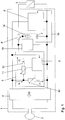
- Fig. 1 shows a schematic diagram of a transponder according to the invention.
- the structure of the transponder according to Fig. 1 corresponds in large part to the transponder in the publication DE 103 48 569 A1 is shown, wherein the entire disclosure content of this document is made by reference to the content of the present application.
- the transponder comprises a circuit arrangement 1 which is connected to an antenna device is connected in the form of an antenna coil 2. Instead of an antenna coil 2, any other suitable antenna device, such as a printed antenna, may be used.
- an actuator 3 is actuated, which is connected to the circuit arrangement 1 for this purpose.
- the actuator 3 may, for example, be a closing magnet or any other optical, acoustic, electrothermal, electrochemical, thermomechanical, electromechanical, electromagnetic, etc. device which, because of its high energy consumption or because of its high inrush current, is not fed directly by the antenna coil 2 can be.
- the circuit arrangement 1 has a rectifier 4 which is connected to the antenna coil 2 on its AC voltage side.
- the rectifier 4 is followed by a charging circuit 5 on its DC side, which can be connected on the output side via a switch 6 to a capacitor 7.
- the capacitor 7 can be connected to the actuator 3 via the switch 6.
- the switching state of the switch 6 is controlled by a transponder circuit 8, which is connected in parallel to the charging circuit.
- the transponder circuit is in particular an integrated circuit in the form of a chip card chip, e.g. a smartcard chip.
- the charging circuit 5 has a control circuit 9, which is connected to the DC side of the rectifier 4 and a first variable resistor 10 and a second variable resistor 11 controls.
- the first variable resistor 10 is connected in parallel with the DC side of the rectifier 4.
- the second variable resistor 11 connects one of the terminals of the DC side of the rectifier 4 via a diode 12 to the switch 6.
- the circuit arrangement 1 further includes a state of charge measuring unit 13, which is connected in parallel with the capacitor 7 and serves to measure the state of charge of the capacitor 7.
- the measuring device 13 is, for example, an AD converter with which the voltage across the capacitor 7 can be measured.
- a measurement data interface 15 is provided between the state of charge measurement unit 13 and the transponder circuit 8, wherein the transponder circuit can interrogate the state of charge measured by the measurement unit 13 via this interface. The measured via the measuring unit 13 state of charge is used to control the triggering of the actuator 3, as will be described in more detail below.
- a charging current measuring unit 14 is connected in series with the capacitor 7, which measures the current flowing through the capacitor charging current, wherein the measured charging current via an interface (not shown) can also be queried by the transponder circuit 8.
- the in Fig. 1 The device 2 is exposed to an alternating magnetic field in a frequency range of 13.56 MHz based on the NFC technology.
- the magnetic alternating field is generated by a transmitting device, for example, from a in Fig. 2 shown reader 21 with connected antenna 22, this reader is integrated in a mobile device 20. Due to the alternating magnetic field, a voltage is induced in the antenna coil 2, which is rectified by the rectifier 4.
- the field strength of the alternating magnetic field varies depending on the distance of the transmitting device from the antenna coil 2. In a corresponding manner also vary the induced voltage and the resulting produced rectified voltage, which serves, inter alia, the supply of the transponder circuit 8.
- the rectified voltage is regulated by the control circuit 9 to a constant preset value.
- the control circuit 9 controls the two variable resistors 10 and 11 so that the rectified voltage assumes the desired default value.
- the current Is is controlled by the control circuit 9 in each case to a value which is required for setting the rectified voltage to the desired default value. Consequently, the current Is is forcibly determined and can not be freely selected. However, the division of the current Is into the partial currents I1 and I2 can be chosen freely.
- the first controllable resistor 10 can initially be set to an infinitely high value and the second variable resistor 11 can be controlled such that the second partial current I2 corresponds to the current Is required for the regulation of the specified value for the rectified voltage.
- the second variable resistor 11 With increasing charging of the capacitor 7, the second variable resistor 11 is set to an ever smaller value. Once the second variable resistor 11 has reached its minimum value, it is also necessary to reduce the value of the first variable resistor 10 in order to keep the rectified voltage constant at the preset value hold.
- the second partial current I2 decreases and the first partial current I1 increases.
- the time required to charge the capacitor 7 can each be reduced to a minimum possible under the given conditions. How long this time actually is, depends decisively on the field strength of the alternating magnetic field in the region of the antenna coil 2, since this determines the induced voltage and thus also the current Is, which is needed to adjust the default value for the rectified voltage.
- the current Is is in turn at most available as a second partial current I2 for charging the capacitor 7. At a high field strength, only a short charging time is needed. With a low field strength, the charging process takes longer.
- a trigger command "activate actuator” is transmitted wirelessly from the transmitting device and received by the antenna device 2.
- This trip command causes the transponder circuit 8 as a rule for switching the switch 6 in a switching position in which the capacitor 7 is discharged via the actuator 3.
- a triggering of the actuator 3 takes place only when the capacitor 7 has a state sufficient for the actuation of the actuator state of charge. According to the invention, it is ensured that a continuation of the charging of the capacitor is effected via a corresponding communication between the transmitting device and the transponder in the presence of a tripping command when the capacitor is insufficiently charged, until the actuator is finally triggered when the charge is sufficient.
- a corresponding flow of such communication will be discussed below with reference to FIG Fig. 3 described.
- Fig. 2 schematically shows the communication of the transponder according to Fig. 1 with a corresponding reader 21, which is an antenna device 22 and is integrated in the mobile device 20. From the transponder is in Fig. 2 schematically reproduced the circuit arrangement 1 and the antenna device 2. Furthermore, the connection of the transponder to the actuator 3 is shown. By the double arrow P1 in Fig. 2 the non-contact NFC communication between the reader and the transponder is indicated, the communication according to the standard ISO / IEC 14443-4. In a preferred variant of the invention described below, in the communication between the transponder and the transmitting device, furthermore, the state of charge and possibly also the charging current of the capacitor 7 are transmitted to the reading device, charging state and charging current passing through the in Fig.
- the mobile device 20 further includes a security element 26 in the form of a security chip, with which a cryptographic authentication between the mobile device and the transponder is ensured, so that only authorized readers can trigger the actuator 3 via the contactless NFC communication.
- the use of the security element 26 is required in particular for safety-critical applications in which the actuator 3 is, for example, part of a locking device which is intended to be opened or closed only by authorized persons.
- Fig. 3 shows the timing of a communication according to the invention for triggering the actuator 3 based on the protocol ISO / IEC 14443-4. It is in Fig. 3 along the horizontal axis t plotted the time, above the axis t of the charge state LZ of the charge storage in the form of the capacitor 7 is reproduced in percent and shown below the time axis t the timing of the signaling between the NFC reader 21 and the transponder according to the invention is.
- the times are reproduced at which the reader emits signals and along the line L2 are reproduced the times at which the transponder emits signals.
- the times along the line L1 and L2 are represented by circles and the transmission of the signals is indicated by corresponding oblique arrows.
- a communication relationship between the transponder and the reader is initially established by the command sequence "Request ⁇ Anticollision ⁇ ATS".
- This structure of the communication relationship is in Fig. 3 schematized by a corresponding rectangle C reproduced.
- a charging current already flows into the charge storage 7, so that the state of charge of the charge storage increases steadily, as by the rising line 40 in the upper part of the Fig. 3 is indicated.
- the security element 25 described above is used. The authentication takes place via a known command sequence based on the command sequence "Get Challenge (time T1) ⁇ Set Random Number (time T2) ⁇ Authentication (time T3) ⁇ Authentication (time T4).
- the reader sends a "activate actuator” to activate the actuator to the transponder.
- This command will be sent out at time T5.
- the actuator can be triggered only when the charge accumulator is charged substantially 100%, but the command "activate actuator” is transmitted at a time at which the charge state of the charge accumulator is only about 50%.
- no activation of the actuator according to the invention in the execution of the tripping command "activate actuator” first checks the state of charge of the charge storage 7. Is the state of charge - as in Fig.
- the first transmission of this WTX request from the transponder takes place according to Fig. 3 at time T6.
- the reader confirms this WTX request with a corresponding WTX response, which is sent out at time T7.
- the Tansponder again checks whether the charge state of the charge storage device 7 is sufficient to trigger the actuator. This is in the scenario of Fig. 3 not yet the case, so that at the time T8 again a WTX request is sent to the reader, which is again answered at the time T9 by a corresponding WTX response.
- the steps of the mutual exchange of WTX requests and WTX responses are repeated until finally a 100% charge of the charge storage in the transponder is detected.
- the 100% Charge is in Fig. 3 indicated by the horizontal line 41. Furthermore, in Fig. 3 the times of mutual sending of WTX requests and WTX responses indicated by corresponding ellipses REQ and RES, which surround the timing of sending the corresponding requests or Responses. With the requests, information about the state of charge is also transmitted in the embodiment described here.
- the requests in the ellipse REQ indicate a charge state of the charge store of 60%, whereas the request sent out at time T6 indicates a charge state of 30%.
- the full charge of the capacitor is according to Fig. 3 at time Tf, whereby the full charge is detected in the transponder at time Te.
- the transponder circuit 8 then closes the switch 6 in order to supply the energy of the capacitor 7 to the actuator 3.
- a corresponding return code (eg "90 00") is sent to the reader for confirmation of the complete execution of the "activate actuator" command.
- the subsequent discharge of the capacitor is in Fig. 3 indicated by the falling edge 42.
- bits 7 and 8 of the WTX request in accordance with standard ISO / IEC 14443-4, which are provided for so-called "power-level indication”.
- a possible coding of the state of charge or charging current is shown in the following table. Bit 8 Bit 7 importance 0 0 Function not supported 0 1 Charge current insufficient; Field energy too low. 1 0 Charge seperator loaded to 30% (0 .. 50%) 1 1 Charge storage 60% charged (50 .. 99%)
- bit assignments are preferably interpreted based on the above table.
- the user of the reader can be signaled that the charging current is insufficient, so that the user as a result, the antenna of the reader the battery-less actuator better aligned, thereby improving the energy transfer between the reader and the transponder.
- a corresponding signaling of an insufficient charging current or the progress of the charge of the capacitor can be carried out on the reading device, for example by an acoustic signal or a display field.
- a variant of the display of the loading progress by a bar has already been described above with reference to FIG Fig. 2 described. In this case, in addition to the progress bar or instead of the progress bar optionally also an optical display of the charging current can be done to allow the user to optimize the orientation of the antenna of the reader with respect to the transponder.
- a special return code can also be sent by the transponder instead of the WTX request.
- the information is encoded that the previously sent trigger command of the reader is not could be executed.
- the reader then sends the command "activate actuator" again, this mechanism is repeated until the charge storage is sufficiently charged and the trip command is finally executed successfully by activating the actuator analogous to the use of WTX requests and WTX responses can.
- the charge state of the charge storage device and the charging current can also be transmitted in the return code.
- the state of charge of the load memory and, where appropriate, the charging current can be signaled on the reader, for example, in turn, on the display of a mobile device in which the reader is integrated.
Description
- Die Erfindung betrifft eine Vorrichtung zum Ansteuern eines Aktuators. Ferner betrifft die Erfindung ein System aus einer derartigen Vorrichtung, einem Aktuator und einer Sendeeinrichtung sowie eine Sendeeinrichtung zur Verwendung in einem solchen System. Darüber hinaus betrifft die Erfindung ein Verfahren zum Ansteuern eines Aktuators.
- Es ist bereits bekannt, einen Aktuator auf kontaktlosem Weg auszulösen. Derartige Aktuatoren werden beispielsweise bei elektronischen Schließzylindern eingesetzt, wobei in einem solchen Anwendungsfall der Aktuator als ein Schließmagnet ausgebildet sein kann, der von einer elektronischen Schaltung angesteuert wird.
- Die Druckschrift
DE 103 48 569 A1 beschreibt eine Vorrichtung zum Ansteuern eines Aktuators basierend auf einer kontaktlosen Kommunikation eines Transponders mit einer Sendeeinrichtung. Der in dieser Druckschrift gezeigte Transponder empfängt über eine Antenneneinrichtung Steuersignale, wobei der Transponder abhängig von den Steuersignalen die Auslösung des Aktuators bewirken kann. Die über die kontaktlose Kommunikation von der Sendeeinrichtung übertragene Energie wird dabei einem Energiespeicher im Transponder zugeführt. Die Energie des Energiespeichers wird zur Auslösung des Aktuators verwendet. Es kann hierbei der Fall auftreten, dass der Energiespeicher zur Auslösung des Aktuators noch nicht ausreichend geladen ist, wenn ein Steuersignal zur Auslösung des Aktuators empfangen wird. In einer solchen Konstellation erfolgt keine Auslösung des Aktuators durch das Steuersignal.
US 2007/0156204 A1 zeigt einen Herzschrittmacher, zu dem kontaktlos Energie übertragen wird.US 5,479,799 zeigt die Merkmale des Oberbegriffs der unabhängigen Ansprüche. - Zur kontaktlosen Kommunikation zwischen einem Lesegerät und einem Transponder wird heutzutage häufig die NFC-Technologie (NFC = Near Field Communication) verwendet. Diesbezüglich wird im Standard ISO/IEC 14443-4 ein Verfahren beschrieben, mit dem ein Transponder dem Lesegerät Informationen über die Stärke des Lesefelds übermitteln kann. Hierzu werden entsprechende Bits des INF-Feldes von sog. WTX-Requests verwendet. Bei den meisten kontaktlosen Anwendungen, wie z.B. der Verwendung von RFID-Chips in Reisepässen oder Kreditkarten, werden Informationen bezüglich der Stärke des Lesefelds jedoch nicht übermittelt und auch nicht benötigt.
- Aufgabe der Erfindung ist es, eine kontaktlose Auslösung eines Aktuators auf einfache und zuverlässige Weise zu ermöglichen. Diese Aufgabe wird durch die Merkmalskombination des Anspruchs 1 gelöst.
- Die erfindungsgemäße Vorrichtung umfasst einen Energiespeicher, beispielsweise in der Form eines Kondensators, zur Speisung eines Aktuators, eine Antenneneinrichtung, mit welcher über eine kontaktlose Kommunikation, insbesondere basierend auf der NFC-Technologie, von einer Sendeeinrichtung Energie zum Laden des Energiespeichers und ein oder mehrere Steuersignale umfassend ein Auslösekommando zum Auslösen des Aktuators empfangbar sind, sowie eine Steuereinheit zur Steuerung der Energiezufuhr vom Energiespeicher zum Aktuator abhängig von den Steuersignalen. Die erfindungsgemäße Vorrichtung ist dabei derart ausgestaltet, dass im Betrieb der Vorrichtung nach Empfang des Auslösekommandos der Ladezustand des Energiespeichers ermittelt wird, wobei bei einem Ladezustand des Energiespeichers, der kleiner als ein zum Auslösen des Aktuators ausreichender Ladezustandsschwellwert ist, ein Antwortsignal zur Fortsetzung der kontaktlosen Kommunikation über die Antenneneinrichtung zum Empfang durch die Sendeeinrichtung ausgesendet wird, und wobei bei einem Ladezustand des Energiespeichers, der größer oder gleich dem Ladezustandsschwellwert ist, die Steuereinrichtung die Energiezufuhr vom Energiespeicher zum Aktuator derart steuert, dass ein Auslösen des Aktuators ermöglicht wird.
- Die Erfindung beruht auf der Idee, eine kontaktlose Kommunikation zwischen einer Ansteuervorrichtung und einer Sendeeinrichtung bis zu einem zur Auslösung des angesteuerten Aktuators ausreichenden Ladezustandswert des Energiespeichers aufrecht zu erhalten, um hierdurch das Auslösen des Aktuators sicherzustellen, selbst wenn bei Empfang des Auslösekommandos ein ausreichender Ladezustand des Energiespeichers noch nicht erreicht ist. Durch das Aufrechterhalten der kontaktlosen Kommunikation wird dabei der Empfang von Energie zum Laden des Energiespeichers fortgesetzt, so dass bei Erreichen eines ausreichenden Ladezustands schließlich der Aktuator ausgelöst werden kann. Die erfindungsgemäße Vorrichtung hat den Vorteil, dass ein übermitteltes Auslösekommando immer geeignet verarbeitet wird, ohne dass eine Fehlermeldung aufgrund eines nicht ausreichend geladenen Energiespeichers zurückgegeben wird. Der zum Auslösen des Aktuators ausreichende Ladezustandsschwellwert kann dabei derart festgelegt sein, dass er mit Sicherheit die Auslösung des Aktuators gewährleistet, d.h. der Ladezustandsschwellwert kann auch über dem unteren Grenzwert liegen, unterhalb dem ein Auslösen des Aktuators nicht möglich ist. Beispielsweise kann der Ladezustandsschwellwert bei im Wesentlichen 100 % Aufladung des Energiespeichers liegen. Der Ladezustandsschwellwert des Energiespeichers kann jedoch auch derart festgelegt, dass der Aktuator nicht auslösbar ist, wenn der Ladezustand des Energiespeichers unterhalb dieses Ladezustandsschwellwerts liegt.
- In einer bevorzugten Ausführungsform ist die Vorrichtung derart ausgestaltet, dass sie ein Bestätigungssignal nach dem Auslösen des Aktuators über die Antenneneinrichtung zum Empfang durch die Sendeeinrichtung aussendet. Vorzugsweise ist das Antwortsignal dabei ein Befehl zur Verlängerung oder zum Neustart einer Wartezeit, welche die Sendeeinrichtung auf das Bestätigungssignal wartet. Der Befehl zur Verlängerung oder zum Neustart der Wartezeit kann insbesondere ein WTX-Request gemäß dem Standard ISO/IEC 14443-4 sein. Die Verwendung eines Befehls zur Verlängerung bzw. zum Neustart einer Wartezeit hat insbesondere den Vorteil, dass auf der Ebene des Übertragungsprotokolls die Wartezeit und somit die kontaktlose Kommunikation verlängert werden kann, ohne dass der Sendeeinrichtung spezielle Codes zur Fortsetzung der kontaktlosen Kommunikation bekannt sein müssen. Es ist jedoch auch möglich, dass das Antwortsignal ein spezieller Wiederholbefehl ist, um die Sendeeinrichtung dazu zu veranlassen, das Auslösekommando erneut auszusenden.
- In einer bevorzugten Variante der erfindungsgemäßen Vorrichtung wird der Ladezustand des Energiespeichers durch eine Ladezustands-Messeinheit zur Messung des Ladezustands ermittelt, wobei die Steuereinheit den Ladezustand des Energiespeichers von der Ladezustands-Messeinheit vorzugsweise über eine Messdatenschnittstelle abfragen kann. Die Verwendung einer derartigen Ladezustands-Messeinheit hat den Vorteil, dass gegebenenfalls auch eine Information über den Ladezustand des Energiespeichers in dem Antwortsignal übertragen werden kann.
- In einer weiteren Variante der erfindungsgemäßen Vorrichtung ist ferner eine Ladestrom-Messeinheit zur Messung des Ladestroms des Energiespeichers vorgesehen, wobei eine Information über den Ladestrom ebenfalls in dem Antwortsignal an die Sendeeinrichtung übertragen werden kann. Bei der Verwendung des ISO/IEC 14443-4 Standards kann die Information über den Ladezustand bzw. den Ladestrom des Energiespeichers besonders einfach durch die bereits für eine Power-Level-Indication vorgesehenen Bits des WTX-Requests codiert werden.
- Die in der erfindungsgemäßen Vorrichtung vorgesehene Steuereinheit ist in einer besonders bevorzugten Ausführungsform ein integrierter Schaltkreis, insbesondere ein Chip für Chipkarten, wodurch besonders kompakte Abmessungen der Vorrichtung erreicht werden. Der Aktuator ist in einer bevorzugten Variante Bestandteil einer Schließeinrichtung, wobei das Schließen und Öffnen der Schließeinrichtung durch den Aktuator ausgelöst wird.
- Neben der soeben beschriebenen Vorrichtung betrifft die Erfindung ferner ein System, umfassend eine Sendeeinrichtung, einen Aktuator und die oben beschriebene erfindungsgemäße Ansteuervorrichtung, wobei der Aktuator von der Ansteuervorrichtung durch ein kontaktlos übertragenes Auslösekommando der Sendeeinrichtung auslösbar ist. Dieses System ist vorzugsweise derart ausgestaltet, dass ein Auslösen des Aktuators nur nach einer erfolgreichen Authentisierung zwischen der Ansteuervorrichtung und der Sendeeinrichtung erfolgen kann, so dass das System auch für sicherheitskritische Anwendungen eingesetzt werden kann.
- Das erfindungsgemäße System wird vorzugsweise in Kombination mit einer Ansteuervorrichtung verwendet, welche als Antwortsignal zur Fortsetzung der kontaktlosen Kommunikation einen Befehl zur Verlängerung bzw. zum Neustart einer Wartezeit einsetzt. Dabei sendet die Sendeeinrichtung nach Empfang dieses Befehls eine Bestätigungsantwort kontaktlos an die Ansteuervorrichtung, welche anschließend erneut den Ladezustand des Energiespeichers ermittelt, wobei bei einem Ladezustand des Energiespeichers, der kleiner als der Ladezustandsschwellwert ist, erneut ein Befehl zur Verlängerung oder zum Neustart der Wartezeit über die Antenneneinrichtung an die Sendeeinrichtung gesendet wird, und wobei bei einem Ladezustand des Energiespeichers der größer oder gleich dem Ladezustandsschwellwert ist, die Steuereinheit der Ansteuervorrichtung zur Auslösung des Aktuators die Energie vom Energiespeicher dem Aktuator zuführt. Vorzugsweise wird hierbei der aus dem Standard ISO/IEC 14443-4 bekannte WTX-Response als Bestätigungsantwort verwendet, wobei der WTX-Response nach Empfang des entsprechenden WTX-Requests von der Sendeinrichtung ausgesendet wird.
- In einer weiteren Ausgestaltung des erfindungsgemäßen Systems ist die Sendeeinrichtung derart ausgestaltet, dass sie im Falle, dass als Antwortsignal ein Wiederholbefehl von der Ansteuereinrichtung ausgesendet wird, das Auslösekommando erneut aussendet.
- Neben dem oben beschriebenen System umfasst die Erfindung ferner eine Sendeeinrichtung zur Verwendung in einem solchen System, wobei die Sendeeinrichtung eine Verarbeitungseinheit für ein kontaktlos empfangenes Antwortsignal zur Fortsetzung der kontaktlosen Kommunikation aufweist, wobei die Verarbeitungseinheit in Antwort auf das Antwortsignal eine Bestätigungsantwort aussendet oder das Auslösekommando erneut aussendet.
- Vorzugsweise kann die Verarbeitungseinheit der Sendeeinrichtung kontaktlos empfangene Informationen über den Ladezustand und/oder den Ladestrom des Energiespeichers verarbeiten, sofern diese Informationen übertragen werden. Die Verarbeitungseinheit umfasst dabei vorzugsweise eine Signalisierungseinheit zur Signalisierung des Ladezustands und/oder des Ladestroms für einen Benutzer. Die Signalisierungseinheit kann dabei ein Anzeigefeld bzw. ein Display oder auch eine akustische Signalisierungseinheit sein. Die Verwendung einer solchen Signalisierungseinheit hat den Vorteil, dass ein Benutzer über den aktuellen Ladezustand des Energiespeichers informiert wird und hieraus ablesen kann, wie viel Zeit in etwa noch bis zur Auslösung des Aktuators benötigt wird. Ebenso kann ein Benutzer bei der Anzeige eines nicht ausreichenden Ladestroms entsprechende Gegenmaßnahmen einleiten, z.B. kann er die Sendeeinrichtung zur Erhöhung des Ladestroms näher an den Aktuator anordnen. Vorzugsweise kann die Verarbeitungseinheit auch automatisiert die Sendeleistung der Sendeeinrichtung erhöhen, wenn der Ladestrom einen vorgegebenen Wert unterschreitet.
- Die Erfindung umfasst ferner ein Verfahren zum Ansteuern eines Aktuators mit einer Ansteuervorrichtung, wobei über eine kontaktlose Kommunikation von einer Sendeeinrichtung Energie zum Laden eines Energiespeichers der Ansteuervorrichtung und ein Auslösekommando zum Auslösen des Aktuators an die Ansteuervorrichtung übertragen wird, wobei nach Empfang des Auslösekommandos in der Ansteuervorrichtung der Ladezustand des Energiespeichers ermittelt wird und bei einem Ladezustand des Energiespeichers, der kleiner als ein zum Auslösen des Aktuators ausreichender Ladezustandsschwellwert ist, ein Antwortsignal zur Fortsetzung der kontaktlosen Kommunikation von der Ansteuervorrichtung an die Sendeeinrichtung gesendet wird, wohingegen bei einem Ladezustand des Energiespeichers, der größer oder gleich dem Ladezustandsschwellwert ist, die Ansteuervorrichtung den Energiespeicher mit dem Aktuator verbindet und dadurch den Aktuator auslöst.
- Ausführungsbeispiele der Erfindung werden nachfolgend anhand der beigefügten Figuren detailliert beschrieben.
- Es zeigen:
- Fig. 1
- eine schematische Darstellung einer Ausführungsform einer erfindungsgemäßen Vorrichtung zum Ansteuern eines Aktuators;
- Fig. 2
- eine schematische Darstellung der kontaktlosen Kommunikation zwischen der Vorrichtung gemäß
Fig. 1 und einer Sendeeinrichtung in einem Mobilfunkgerät; - Fig. 3
- eine schematische Darstellung des zeitlichen Ablaufs einer Kommunikation zwischen einem erfindungsgemäßen Transponder und einer Sendeeinrichtung; und
- Fig. 4
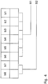
- eine schematische Darstellung des INF-Feldes eines WTX-Requests gemäß dem Standard ISO/IEC 14443-4.
- Nachfolgend wird die Erfindung basierend auf einer sog. NFC-Kommunikation (NFC = Near Field Communication) beschrieben, bei der drahtlos bzw. kontaktlos zwischen einem Transponder umfassend einen RFID-Chip (RFID = Radio Frequency Identification) und einem entsprechenden NFC-Lesegerät Signale ausgetauscht werden. Der Transponder entspricht hierbei der Ansteuervorrichtung und das NFC-Lesegerät der Sendeeinrichtung im Sinne der Ansprüche.
-
Fig. 1 zeigt ein Prinzipschaltbild eines erfindungsgemäßen Transponders. Der Aufbau des Transponders gemäßFig. 1 entspricht dabei in großen Teilen dem Transponder, der in der DruckschriftDE 103 48 569 A1 gezeigt ist, wobei der gesamte Offenbarungsgehalt dieser Druckschrift durch Verweisung zum Inhalt der vorliegenden Anmeldung gemacht wird. Der Transponder umfasst eine Schaltungsanordnung 1, welche an eine Antenneneinrichtung in der Form einer Antennenspule 2 angeschlossen ist. Anstatt einer Antennenspule 2 kann auch jede andere geeignete Antenneneinrichtung, wie z.B. eine gedruckte Antenne, verwendet werden. Mit der inFig. 1 gezeigten Vorrichtung wird ein Aktuator 3 angesteuert, der hierzu mit der Schaltungsanordnung 1 verbunden ist. Bei dem Aktuator 3 kann es sich beispielsweise um einen Schließmagneten oder um eine sonstige optische, akustische, elektrothermische, elektrochemische, thermomechanische, elektromechanische, elektromagnetische usw. Einrichtung handeln, die aufgrund ihres hohen Energieverbrauchs oder aufgrund ihres hohen Einschaltstroms nicht unmittelbar von der Antennenspule 2 gespeist werden kann. - Die Schaltungsanordnung 1 weist einen Gleichrichter 4 auf, der auf seiner Wechselspannungsseite mit der Antennenspule 2 verbunden ist. Dem Gleichrichter 4 ist auf seiner Gleichspannungsseite eine Ladeschaltung 5 nachgeschaltet, die ausgangsseitig über einen Schalter 6 mit einem Kondensator 7 verbunden werden kann. Alternativ zur Ladeschaltung 5 kann der Kondensator 7 über den Schalter 6 mit dem Aktuator 3 verbunden werden. Der Schaltzustand des Schalters 6 wird von einer Transponderschaltung 8 gesteuert, die der Ladeschaltung parallel geschaltet ist. Die Transponderschaltung ist dabei insbesondere eine integrierte Schaltung in der Form eines Chips für Chipkarten, z.B. eines Smartcard-Chips.
- Die Ladeschaltung 5 weist eine Regelschaltung 9 auf, die an der Gleichspannungsseite des Gleichrichters 4 angeschlossen ist und einen ersten regelbaren Widerstand 10 sowie einen zweiten regelbaren Widerstand 11 steuert. Der erste regelbare Widerstand 10 ist der Gleichspannungsseite des Gleichrichters 4 parallel geschaltet. Der zweite regelbare Widerstand 11 verbindet einen der Anschlüsse der Gleichspannungsseite des Gleichrichters 4 über eine Diode 12 mit dem Schalter 6.
- Im Unterschied zu der in der Druckschrift
DE 103 48 569 A1 gezeigten Vorrichtung beinhaltet die Schaltungsanordnung 1 ferner eine Ladezustands-Messeinheit 13, welche zum Kondensator 7 parallel geschaltet ist und zur Messung des Ladezustands des Kondensators 7 dient. Die Messeinrichtung 13 ist beispielsweise ein AD-Wandler, mit dem die Spannung am Kondensator 7 gemessen werden kann. Ferner ist eine Messdatenschnittstelle 15 zwischen der Ladezustands-Messeinheit 13 und der Transponderschaltung 8 vorgesehen, wobei die Transponderschaltung über diese Schnittstelle den von der Messeinheit 13 gemessenen Ladezustand abfragen kann. Der über die Messeinheit 13 gemessene Ladezustand wird dabei zur Steuerung der Auslösung des Aktuators 3 verwendet, wie weiter unten noch näher beschrieben wird. Darüber hinaus ist mit dem Kondensator 7 eine Ladestrom-Messeinheit 14 in Reihe geschaltet, welche den durch den Kondensator fließenden Ladestrom misst, wobei der gemessene Ladestrom über eine (nicht gezeigte) Schnittstelle ebenfalls von der Transponderschaltung 8 abgefragt werden kann. - Der in
Fig. 1 gezeigten Vorrichtung liegt folgende Funktionsweise zu Grunde: die Antennenspule 2 ist einem magnetischen Wechselfeld in einem Frequenzbereich von 13,56 MHz basierend auf der NFC-Technologie ausgesetzt. Das magnetische Wechselfeld wird dabei von einer Sendeeinrichtung erzeugt, beispielsweise von einem inFig. 2 gezeigten Lesegerät 21 mit angeschlossener Antenne 22, wobei dieses Lesegerät in einem Mobilfunkgerät 20 integriert ist. Aufgrund des magnetischen Wechselfeldes wird in der Antennenspule 2 eine Spannung induziert, die von dem Gleichrichter 4 gleichgerichtet wird. Die Feldstärke des magnetischen Wechselfelds variiert abhängig von der Entfernung der Sendeeinrichtung von der Antennenspule 2. In entsprechender Weise variieren auch die induzierte Spannung und die daraus hergestellte gleichgerichtete Spannung, die unter anderem der Versorgung der Transponderschaltung 8 dient. Um eine konstante Versorgungsspannung zu erhalten, wird die gleichgerichtete Spannung von der Regelschaltung 9 auf einen konstanten Vorgabewert geregelt. Hierzu steuert die Regelschaltung 9 die beiden variablen Widerstände 10 und 11 so an, dass die gleichgerichtete Spannung den gewünschten Vorgabewert annimmt. Dabei fließt durch die beiden variablen Widerstände 10 und 11 insgesamt ein Strom Is, der sich bei dem inFig. 1 gezeigten ersten Schaltzustand, bei dem der Schalter 6 die Diode 12 mit dem Kondensator 7 verbindet, aus einem ersten Teilstrom I1 durch den ersten regelbaren Widerstand 10 und einem zweiten Teilstrom I2 durch den zweiten regelbaren Widerstand 11 zusammensetzt. Der Strom Is wird von der Regelschaltung 9 jeweils auf einen Wert geregelt, der zum Einstellen der gleichgerichteten Spannung auf den gewünschten Vorgabewert erforderlich ist. Folglich ist der Strom Is zwangsbestimmt und kann nicht frei gewählt werden. Allerdings kann die Aufteilung des Stroms Is in die Teilströme I1 und I2 frei gewählt werden. - In der Vorrichtung der
Fig. 1 wird die Aufteilung des Stroms Is in die Teilströme I1 und I2 so vorgenommen, dass der zweite Teilstrom I2 möglichst groß ist, um den Kondensator 7 möglichst schnell aufzuladen. Hierzu kann der erste regelbare Widerstand 10 zunächst auf einen unendlich hohen Wert eingestellt werden und der zweite regelbare Widerstand 11 so angesteuert werden, dass der zweite Teilstrom I2 dem für die Einregelung des Vorgabewerts für die gleichgerichtete Spannung erforderlichen Strom Is entspricht. Mit zunehmender Aufladung des Kondensators 7 wird der zweite regelbare Widerstand 11 auf einen immer kleineren Wert eingestellt. Sobald der zweite regelbare Widerstand 11 seinen Minimalwert erreicht hat, ist es erforderlich, auch den Wert des ersten regelbaren Widerstands 10 zu reduzieren, um die gleichgerichtete Spannung auch weiterhin konstant beim Vorgabewert zu halten. Entsprechend nimmt der zweite Teilstrom I2 ab und der erste Teilstrom I1 zu. Auf diese Weise kann die zum Aufladen des Kondensators 7 benötigte Zeit jeweils auf ein unter den gegebenen Bedingungen mögliches Minimum reduziert werden. Wie lange diese Zeit tatsächlich ist, hängt entscheidend von der Feldstärke des magnetischen Wechselfeldes im Bereich der Antennenspule 2 ab, da dadurch die induzierte Spannung und somit auch der Strom Is festgelegt wird, der zur Einregelung des Vorgabewerts für die gleichgerichtete Spannung benötigt wird. Der Strom Is steht wiederum maximal als zweiter Teilstrom I2 zum Laden des Kondensators 7 zur Verfügung. Bei einer hohen Feldstärke wird nur eine kurze Ladezeit benötigt. Bei einer niedrigen Feldstärke dauert der Ladevorgang entsprechend länger. - Um den Aktuator 3 der
Fig. 1 auszulösen, wird von der Sendeeinrichtung ein Auslösekommando "activate actuator" drahtlos ausgesendet und von der Antenneneinrichtung 2 empfangen. Dieses Auslösekommando veranlasst die Transponderschaltung 8 im Regelfall zum Umschalten des Schalters 6 in eine Schaltposition, in welcher der Kondensator 7 über den Aktuator 3 entladen wird. Hierbei ist zu beachten, dass ein Auslösen des Aktuators 3 jedoch nur dann erfolgt, wenn der Kondensator 7 einen zur Betätigung des Aktuators ausreichenden Ladezustand aufweist. Erfindungsgemäß wird sichergestellt, dass über eine entsprechende Kommunikation zwischen der Sendeeinrichtung und dem Transponder bei Vorliegen eines Auslösekommandos bei nicht ausreichender Ladung des Kondensators eine Fortsetzung der Aufladung des Kondensators bewirkt wird, bis schließlich bei ausreichender Ladung der Aktuator ausgelöst wird. Ein entsprechender Ablauf einer solchen Kommunikation wird weiter unten mit Bezug aufFig. 3 beschrieben. -
Fig. 2 zeigt schematisch die Kommunikation des Transponders gemäßFig. 1 mit einem entsprechenden Lesegerät 21, welches eine Antenneneinrichtung 22 aufweist und in dem Mobilfunkgerät 20 integriert ist. Von dem Transponder ist inFig. 2 schematisch die Schaltungsanordnung 1 sowie die Antenneneinrichtung 2 wiedergegeben. Ferner ist die Verbindung des Transponders zum Aktuator 3 gezeigt. Durch den Doppelpfeil P1 inFig. 2 wird die kontaktlose NFC-Kommunikation zwischen dem Lesegerät und dem Transponder angedeutet, wobei die Kommunikation gemäß dem Standard ISO/IEC 14443-4 erfolgt. In einer bevorzugten, weiter unten beschriebenen Variante der Erfindung wird bei der Kommunikation zwischen Transponder und Sendeeinrichtung ferner der Ladezustand und gegebenenfalls auch der Ladestrom des Kondensators 7 an das Lesegerät übertragen, wobei Ladezustand und Ladestrom durch die inFig. 1 gezeigten Messeinrichtungen 13 bzw. 14 gemessen wurden. Diese Messgrößen können in dem Display 23 des Mobilfunkgeräts 20 wiedergegeben werden, wobei inFig. 2 eine vergrößerte Ansicht des Displays 23 gezeigt ist. Man erkennt, dass auf dem Display gerade der Ladezustand des Kondensators in einem horizontalen Anzeigefeld 24 in der Form eines schraffiert gezeigten Fortschrittsbalkens 25 wiedergegeben ist. Füllt der Balken 25 das Anzeigefeld 24 komplett aus, ist der Kondensator zu 100 % aufgeladen. Das Mobilfunkgerät 20 enthält ferner ein Sicherheitselement 26 in der Form eines Sicherheitschips, mit dem eine kryptographische Authentisierung zwischen dem Mobilfunkgerät und dem Transponder sichergestellt ist, so dass nur autorisierte Lesegeräte den Aktuator 3 über die kontaktlose NFC-Kommunikation auslösen können. Die Verwendung des Sicherheitselements 26 ist insbesondere bei sicherheitskritischen Anwendungen erforderlich, bei denen der Aktuator 3 beispielsweise Bestandteil einer Schließeinrichtung ist, die nur von autorisierten Personen geöffnet bzw. geschlossen werden soll. -
Fig. 3 zeigt den zeitlichen Ablauf einer erfindungsgemäßen Kommunikation zur Auslösung des Aktuators 3 basierend auf dem Protokoll ISO/IEC 14443-4. Dabei ist inFig. 3 entlang der horizontalen Achse t die Zeit aufgetragen, wobei oberhalb der Achse t der Ladezustand LZ des Ladungsspeichers in der Form des Kondensators 7 in Prozent wiedergegeben ist und unterhalb der Zeitachse t der zeitliche Ablauf der Signalisierung zwischen dem NFC-Lesegerät 21 und dem erfindungsgemäßen Transponder gezeigt ist. Entlang der Linie L1 sind dabei die Zeitpunkte wiedergegeben, zu denen das Lesegerät Signale aussendet und entlang der Linie L2 sind die Zeitpunkte wiedergegeben, zu denen der Transponder Signale aussendet. Die Zeitpunkte entlang der Linie L1 und L2 sind dabei durch Kreise dargestellt und die Übertragung der Signale ist durch entsprechende schräg verlaufende Pfeile angedeutet. - Gelangt der erfindungsgemäße Transponder in das Ansprechfeld des Lesegeräts 21, wird zunächst eine Kommunikationsbeziehung zwischen dem Transponder und dem Lesegerät durch die Befehlsfolge "Request → Anticollision → ATS" aufgebaut. Dieser Aufbau der Kommunikationsbeziehung ist in
Fig. 3 schematisiert durch ein entsprechendes Rechteck C wiedergegeben. Beim Aufbau der Kommunikationsbeziehung fließt bereits ein Ladestrom in den Ladungsspeicher 7, so dass der Ladezustand des Ladungsspeichers stetig zunimmt, wie durch die ansteigende Linie 40 im oberen Teil derFig. 3 angedeutet ist. Nach Aufbau der Kommunikationsbeziehung beginnt ab dem Zeitpunkt T1 die gegenseitige Authentisierung zwischen dem Lesegerät und dem batterielosen Aktuator. Dabei kommt das oben beschriebene Sicherheitselement 25 zum Einsatz. Die Authentisierung erfolgt über einen bekannten Befehlsablauf basierend auf der Kommandofolge "Get Challenge (Zeitpunkt T1) → Set Random Number (Zeitpunkt T2) → Authentication (Zeitpunkt T3) → Authentication (Zeitpunkt T4). - Das Lesegerät sendet unmittelbar nach dem erfolgreichen Abschluss der Authentisierung ein Auslösekommando ("activate actuator") zum Aktivieren des Aktuators an den Transponder. Dieses Kommando wird zum Zeitpunkt T5 ausgesendet. In dem in
Fig. 3 gezeigten Szenario kann der Aktuator nur bei einer Aufladung des Ladungsspeichers von im Wesentlichen 100 % ausgelöst werden, wobei das Kommando "activate actuator" jedoch zu einem Zeitpunkt übermittelt wird, bei dem der Ladezustand des Ladungsspeichers bei lediglich ca. 50 % liegt. Um zu vermeiden, dass trotz des Auslösekommandos wegen mangelnder Ladung des Kondensators keine Aktivierung des Aktuators erfolgt, wird erfindungsgemäß bei der Abarbeitung des Auslösekommandos "activate actuator" zunächst der Ladezustand des Ladungsspeichers 7 überprüft. Ist der Ladezustand - wie inFig. 3 gezeigt - zu gering, ist es vorgesehen, keine Fehlermeldung zu senden, sondern vor dem Ablaufen der entsprechenden Frame-Waiting-Time des Protokolls ISO/IEC 14443-4 einen WTX-Request (WTX = Waiting Time Extension) zu senden, um die Frame-Waiting-Time neu zu starten bzw. zu verlängern. - Das erstmalige Aussenden dieses WTX-Requests von dem Transponder erfolgt gemäß
Fig. 3 zum Zeitpunkt T6. Das Lesegerät bestätigt diesen WTX-Request mit einem entsprechenden WTX-Response, der zum Zeitpunkt T7 ausgesendet wird. Nach Empfang des WTX-Response überprüft der Tansponder erneut, ob der Ladezustand des Ladungsspeichers 7 zur Auslösung des Aktuators ausreicht. Dies ist im Szenario derFig. 3 noch nicht der Fall, so dass zum Zeitpunkt T8 nochmals ein WTX-Request an das Lesegerät gesendet wird, der zum Zeitpunkt T9 wiederum durch einen entsprechenden WTX-Response beantwortet wird. Wie sich ausFig. 3 ergibt, werden nunmehr die Schritte des gegenseitigen Austauschs von WTX-Requests und WTX-Responses so lange wiederholt, bis schließlich eine 100%-ige Aufladung des Ladungsspeichers im Transponder festgestellt wird. Die 100%-ige Aufladung ist inFig. 3 durch die horizontale Linie 41 angedeutet. Ferner sind inFig. 3 die Zeitpunkte des gegenseitigen Aussendens von WTX-Requests und WTX-Responses durch entsprechende Ellipsen REQ bzw. RES angedeutet, welche die Zeitpunkte des Aussendens der entsprechenden Requests bzw. Responses umranden. Mit den Requests wird in der hier beschriebenen Ausführungsform auch eine Information über den Ladezustand übermittelt. Die Requests in der Ellipse REQ zeigen dabei einen Ladezustand des Ladungsspeichers von 60 % an, wohingegen der zum Zeitpunkt T6 ausgesendete Request einen Ladezustand von 30 % angibt. - Die volle Aufladung des Kondensators liegt gemäß
Fig. 3 zum Zeitpunkt Tf vor, wobei die volle Aufladung in dem Transponder zum Zeitpunkt Te festgestellt wird. Zu diesem Zeitpunkt schließt dann die Transponderschaltung 8 den Schalter 6, um die Energie des Kondensators 7 dem Aktuator 3 zuzuführen. Gleichzeitig wird ein entsprechender Return-Code (z.B. "90 00") an das Lesegerät zur Bestätigung der vollständigen Ausführung des Kommandos "activate actuator" gesendet. Die nachfolgende Entladung des Kondensators ist inFig. 3 durch die abfallende Flanke 42 angedeutet. - In einer bevorzugten Variante der Erfindung ist es vorgesehen, dass mit den von dem Transponder ausgesendeten WTX-Requests auch Informationen über den Ladezustand und den Ladestrom übertragen werden, wobei der Ladezustand bzw. der Ladestrom durch die Messeinrichtungen 13 bzw. 14 der
Fig. 1 gemessen werden können. Zur Übermittlung des Ladezustands bzw. des Ladestroms werden vorzugsweise die Bits 7 und 8 des WTX-Requests gemäß dem Standard ISO/IEC 14443-4 verwendet, welche zur sog. "Power-Level-Indication" vorgesehen sind. Eine mögliche Codierung des Ladezustands bzw. Ladestroms ist in nachfolgender Tabelle wiedergegeben:.Bit 8 Bit 7 Bedeutung 0 0 Funktion nicht unterstützt 0 1 Ladestrom nicht ausreichend; Feldenergie zu gering. 1 0 Ladungssepicher zu 30 % geladen (0 .. 50 %) 1 1 Ladungsspeicher zu 60 % geladen (50 .. 99 %) - Eine Darstellung des Ladezustands von 100 % wird nicht benötigt, da in diesem Zustand der Aktuator sofort ausgelöst wird.
- Der Aufbau eines WTX-Requests gemäß dem Standard ISO/IEC 14443-4 ist in
Fig. 4 dargestellt. Der Bitbereich B1, der die Bits b1 bis b6 umfasst, codiert dabei den sog. WTXM-Wert, der zur Definition einer temporären Frame-Waiting-Time verwendet wird. Der Bitbereich B2 bezeichnet die Bits b7 und b8, welche zur Power-Level-Indication vorgesehen sind. Gemäß dem Standard ISO/IEC 14443-4 ist dabei folgende Codierung für die Bitbelegungen vorgesehen: - b8 = 0, b7 = 0: Gerät unterstützt keine "Power-Level-Indication"
- b8 = 0, b7 = 1: nicht ausreichende Leistung für volle Funktionalität
- b8 = 1, b7 = 0: ausreichende Leistung für volle Funktionalität
- b8 = 1, b7 = 1: mehr als ausreichend Leistung für volle Funktionalität.
- Die Interpretation dieser "Power-Level-Indication" ist dabei für das Lesegerät optional. Erfindungsgemäß werden die Bitbelegungen vorzugsweise basierend auf der obigen Tabelle interpretiert.
- Unter Umständen ist die Feldstärke des von dem Lesegerät ausgesendeten magnetischen Wechselfeldes zu gering, um einen ausreichenden Ladestrom zur Ladung des Ladungsspeichers zu erzeugen. Gemäß der obigen Tabelle kann es deshalb vorgesehen sein, den Zustand eines nicht ausreichenden Ladestroms dem Lesegerät über eine entsprechende Codierung von Bit 7 und Bit 8 im WTX-Request zu signalisieren (siehe Codierung "Bit 8 = 0, Bit 7 = 1"). Das Lesegerät kann daraufhin gegebenenfalls seine Sendeleistung erhöhen. In solchen Fällen, in denen eine Erhöhung der Sendeleistung nicht möglich ist, z.B. wenn das Lesegerät in einem batterieversorgten Mobilfunkgerät vorgesehen ist, kann dem Benutzer des Lesegeräts signalisiert werden, dass der Ladestrom nicht ausreicht, so dass der Benutzer als Folge die Antenne des Lesegeräts gegenüber dem batterielosen Aktuator besser ausrichtet, um dadurch die Energieübertragung zwischen dem Lesegerät und dem Transponder zu verbessern. Eine entsprechende Signalisierung eines nicht ausreichenden Ladestroms bzw. des Fortschritts der Ladung des Kondensators kann am Lesegerät beispielsweise durch ein akustisches Signal oder ein Anzeigefeld erfolgen. Eine Variante der Anzeige des Ladefortschritts durch einen Balken wurde bereits im Vorangegangenen mit Bezug auf
Fig. 2 beschrieben. Dabei kann neben dem Fortschrittsbalken oder anstatt des Fortschrittsbalkens gegebenenfalls auch eine optische Anzeige des Ladestroms erfolgen, um dem Benutzer die Optimierung der Ausrichtung der Antenne des Lesegeräts in Bezug auf den Transponder zu ermöglichen. - Anstatt der oben beschriebenen Verwendung der WTX-Requests bzw. WTX-Responses zur Sicherstellung eines ausreichenden Ladezustands zur Auslösung des Aktuators kann in einer Variante der Erfindung gegebenenfalls auch ein spezieller Return-Code von dem Transponder anstatt des WTX-Requests gesendet werden. In dem Return-Code wird die Information codiert, dass das zuvor gesendete Auslösekommando des Lesegeräts nicht ausgeführt werden konnte. Als Folge sendet das Lesegerät anschließend das Kommando "activate actuator" erneut, wobei dieser Mechanismus analog zur Verwendung der WTX-Requests und WTX-Responses so lange wiederholt wird, bis der Ladungsspeicher ausreichend geladen ist und das Auslösekommando schließlich erfolgreich durch Aktivieren des Aktuators ausgeführt werden kann. In dem Return-Code kann gegebenenfalls auch der Ladezustand des Ladungsspeichers sowie der Ladestrom mit übertragen werden. Auch bei dieser Variante kann der Ladezustand des Ladespeichers und gegebenenfalls der Ladestrom am Lesegerät signalisiert werden, beispielsweise wiederum auf dem Display eines Mobilfunkgeräts, in dem das Lesegerät integriert ist.
Claims (16)
- Vorrichtung zum Ansteuern eines Aktuators (3), mit einem Energiespeicher (7) zur Speisung des Aktuators (3), einer Antenneneinrichtung (2), mit welcher über eine kontaktlose Kommunikation von einer Sendeeinrichtung (21) Energie zum Laden des Energiespeichers (7) und ein oder mehrere Steuersignale umfassend ein Auslösekommando zum Auslösen des Aktuators (3) empfangbar sind, und einer Steuereinheit (8) zur Steuerung der Energiezufuhr vom Energiespeicher (7) zum Aktuator (3) abhängig von den Steuersignalen, dadurch gekennzeichnet, dass die Vorrichtung derart ausgestaltet ist, dass nach Empfang des Auslösekommandos der Ladezustand des Energiespeichers (7) ermittelt wird, wobei bei einem Ladezustand des Energiespeichers (7), der kleiner als ein zum Auslösen des Aktuators (3) ausreichender Ladezustandsschwellwert ist, ein Antwortsignal zur Fortsetzung der kontaktlosen Kommunikation über die Antenneneinrichtung (2) zum Empfang durch die Sendeeinrichtung (21) ausgesendet wird, und wobei bei einem Ladezustand des Energiespeichers (7), der größer oder gleich dem Ladezustandsschwellwert ist, die Steuereinheit (8) die Energiezufuhr vom Energiespeicher (7) zum Aktuator (3) derart steuert, das ein Auslösen des Aktuators ermöglicht wird.
- Vorrichtung nach Anspruch 1, dadurch gekennzeichnet, dass die kontaktlose Kommunikation eine NFC-Kommunikation ist.
- Vorrichtung nach Anspruch 1 oder 2, dadurch gekennzeichnet, dass der Ladezustandsschwellwert des Energiespeichers (7) derart festgelegt ist, dass der Aktuator (3) nicht auslösbar ist, wenn der Ladezustand des Energiespeichers (7) unterhalb des Ladezustandsschwellwerts liegt.
- Vorrichtung nach einem der vorhergehenden Ansprüche, dadurch gekennzeichnet, dass die Vorrichtung derart ausgestaltet ist, dass sie ein Bestätigungssignal nach dem Auslösen des Aktuators (3) über die Antenneneinrichtung (2) zum Empfang durch die Sendeeinrichtung (21) aussendet.
- Vorrichtung nach Anspruch 4, dadurch gekennzeichnet, dass das Antwortsignal ein Befehl zur Verlängerung oder zum Neustart einer Wartezeit ist, welche die Sendeeinrichtung (21) auf das Bestätigungssignal wartet.
- Vorrichtung nach Anspruch 5, dadurch gekennzeichnet, dass der Befehl zur Verlängerung oder zum Neustart der Wartezeit ein WTX-Request gemäß dem Standard ISO/IEC 14443-4 ist.
- Vorrichtung nach einem der vorhergehenden Ansprüche, dadurch gekennzeichnet, dass das Antwortsignal ein Wiederholbefehl ist, um die Sendeeinrichtung (21) dazu zu veranlassen, das Auslösekommando erneut auszusenden.
- Vorrichtung nach einem der vorhergehenden Ansprüche, dadurch gekennzeichnet, dass die Vorrichtung eine Ladezustands-Messeinheit (13) zur Messung des Ladezustands des Energiespeichers (7) enthält.
- Vorrichtung nach Anspruch 8, dadurch gekennzeichnet, dass die Steuereinheit (8) den Ladezustand des Energiespeichers (7) von der Ladezustands-Messeinheit (13) über eine Messdatenschnittstelle (15) abfragen kann.
- Vorrichtung nach Anspruch 8 oder 9, dadurch gekennzeichnet, dass das Antwortsignal eine Information über den Ladezustand des Energiespeichers (7) enthält.
- Vorrichtung nach einem der vorhergehenden Ansprüche, dadurch gekennzeichnet, dass die Vorrichtung eine Ladestrom-Messeinheit (14) zur Messung des Ladestroms des Energiespeichers (7) umfasst.
- Vorrichtung nach Anspruch 11, dadurch gekennzeichnet, dass das Antwortsignal eine Information über den Ladestrom des Energiespeichers (7) enthält.
- Vorrichtung nach einem der vorhergehenden Ansprüche in Kombination mit Anspruch 6 und Anspruch 10 oder 12, dadurch gekennzeichnet, dass die zur Power-Level-Inidication vorgesehenen Bits des WTX-Requests die Information über den Ladezustand des Energiespeichers (7) und/oder den Ladestrom des Energiespeichers (7) enthalten.
- Vorrichtung nach einem der vorhergehenden Ansprüche, dadurch gekennzeichnet, dass der Aktuator (8) Bestandteil einer Schließeinrichtung ist.
- System, umfassend eine Sendeeinrichtung (21), einen Aktuator (3) und eine Ansteuervorrichtung (1, 2) zum Ansteuern des Aktuators (3), wobei der Aktuator (3) von der Ansteuervorrichtung (1, 2) durch ein kontaklos übertragenes Auslösekommando der Sendeeinrichtung (21) auslösbar ist, dadurch gekennzeichnet, dass die Ansteuervorrichtung (1, 2) gemäß einem der vorhergehenden Ansprüche ausgebildet ist.
- Verfahren zum Ansteuern eines Aktuators (3) mit einer Ansteuervorrichtung (1, 2), wobei über eine kontaktlose Kommunikation von einer Sendeeinrichtung (21) Energie zum Laden eines Energiespeichers (7) der Ansteuervorrichtung (1, 2) und ein Auslösekommando zum Auslösen des Aktuators (3) an die Ansteuervorrichtung (1, 2) übertragen wird, dadurch gekennzeichnet, dass nach Empfang des Auslösekommandos in der Ansteuervorrichtung (1, 2) der Ladezustand des Energiespeichers (7) ermittelt wird, wobei bei einem Ladezustand des Energiespeichers (7), der kleiner als ein zum Auslösen des Aktuators (3) ausreichender Ladezustandsschwellwerts ist, ein Antwortsignal zur Fortsetzung der kontaktlosen Kommunikation von der Ansteuervorrichtung (1, 2) zum Empfang durch die Sendeeinrichtung (21) ausgesendet wird, und wobei bei einem Ladezustand des Energiespeichers (7), der größer oder gleich dem Ladezustandsschwellwert ist, die Ansteuervorrichtung (1, 2) den Energiespeicher (7) mit dem Aktuator (3) verbindet und dadurch den Aktuator (3) auslöst.
Applications Claiming Priority (2)
| Application Number | Priority Date | Filing Date | Title |
|---|---|---|---|
| DE102008005059A DE102008005059A1 (de) | 2008-01-18 | 2008-01-18 | Vorrichtung zum Ansteuern eines Aktuators |
| PCT/EP2009/050474 WO2009090235A2 (de) | 2008-01-18 | 2009-01-16 | Vorrichtung zum ansteuern eines aktuators |
Publications (2)
| Publication Number | Publication Date |
|---|---|
| EP2235694A2 EP2235694A2 (de) | 2010-10-06 |
| EP2235694B1 true EP2235694B1 (de) | 2018-05-16 |
Family
ID=40785872
Family Applications (1)
| Application Number | Title | Priority Date | Filing Date |
|---|---|---|---|
| EP09702712.2A Not-in-force EP2235694B1 (de) | 2008-01-18 | 2009-01-16 | Vorrichtung zum ansteuern eines aktuators |
Country Status (4)
| Country | Link |
|---|---|
| US (1) | US8482377B2 (de) |
| EP (1) | EP2235694B1 (de) |
| DE (1) | DE102008005059A1 (de) |
| WO (1) | WO2009090235A2 (de) |
Families Citing this family (9)
| Publication number | Priority date | Publication date | Assignee | Title |
|---|---|---|---|---|
| FR2945162A1 (fr) * | 2009-04-30 | 2010-11-05 | Pascal Metivier | Systeme d'alimentation externe d'une serrure comportant des moyens de communication sans contact de type nfc |
| US20140316612A1 (en) * | 2012-01-05 | 2014-10-23 | Rob Bingle | Vehicle access system |
| FR2987475B1 (fr) * | 2012-02-24 | 2016-07-08 | Stmicroelectronics Rousset | Recharge d'un dispositif nfc |
| GB2501729A (en) * | 2012-05-02 | 2013-11-06 | Itso Ltd | Ticketing system using NFC tags and portable user device |
| WO2014150649A1 (en) * | 2013-03-22 | 2014-09-25 | Utc Fire And Security Americas Corporation, Inc. | Electronic lock with selectable power sources |
| US10291292B2 (en) | 2014-09-02 | 2019-05-14 | Johnson Controls Technology Company | Wireless sensor with near field communication circuit |
| US9732977B2 (en) | 2014-09-02 | 2017-08-15 | Johnson Controls Technology Company | Systems and methods for configuring and communicating with HVAC devices |
| US9500006B2 (en) * | 2014-09-24 | 2016-11-22 | Vemus Endustriyel Elektronik Sanayi Ve Ticaret Limited Sirketi | Easily managed electronic cabinet lock |
| US10326497B2 (en) * | 2017-04-11 | 2019-06-18 | Honeywell International Inc. | Expansion modules with switches and external communication |
Family Cites Families (9)
| Publication number | Priority date | Publication date | Assignee | Title |
|---|---|---|---|---|
| US5479799A (en) * | 1994-10-27 | 1996-01-02 | Kilman Electriloc Company | Key and bolt lock device |
| US5591217A (en) | 1995-01-04 | 1997-01-07 | Plexus, Inc. | Implantable stimulator with replenishable, high value capacitive power source and method therefor |
| EP1011792B1 (de) | 1997-02-26 | 2005-12-07 | Alfred E. Mann Foundation for Scientific Research | Batterie-betriebsgerät zur implantation in einem patienten |
| WO1999042173A1 (en) | 1998-02-23 | 1999-08-26 | Medtronic, Inc. | Rf coupled, implantable medical device with rechargeable back-up power source |
| FI20002493A (fi) | 2000-11-14 | 2002-05-15 | Salcomp Oy | Teholähdejärjestely ja induktiivisesti kytketty akkulaturi, jossa on langattomasti kytketty ohjaus, ja menetelmä teholähdejärjestelyn ja induktiivisesti kytketyn akkulaturin ohjaamiseksi langattomasti |
| DE10348569A1 (de) | 2003-10-20 | 2005-05-25 | Giesecke & Devrient Gmbh | Vorrichtung zum Ansteuern eines Aktuators |
| DE102004036358B4 (de) | 2004-07-27 | 2016-11-03 | Giesecke & Devrient Gmbh | Dosiervorrichtung |
| DE102004039650A1 (de) | 2004-08-16 | 2006-03-09 | Giesecke & Devrient Gmbh | Flexibles kontaktloses Aufladen eines Akkumulators |
| US7720547B2 (en) * | 2006-01-04 | 2010-05-18 | Kenergy, Inc. | Extracorporeal power supply with a wireless feedback system for an implanted medical device |
-
2008
- 2008-01-18 DE DE102008005059A patent/DE102008005059A1/de not_active Withdrawn
-
2009
- 2009-01-16 WO PCT/EP2009/050474 patent/WO2009090235A2/de active Application Filing
- 2009-01-16 US US12/735,437 patent/US8482377B2/en active Active
- 2009-01-16 EP EP09702712.2A patent/EP2235694B1/de not_active Not-in-force
Non-Patent Citations (1)
| Title |
|---|
| None * |
Also Published As
| Publication number | Publication date |
|---|---|
| EP2235694A2 (de) | 2010-10-06 |
| US8482377B2 (en) | 2013-07-09 |
| WO2009090235A2 (de) | 2009-07-23 |
| WO2009090235A3 (de) | 2009-09-17 |
| DE102008005059A1 (de) | 2009-07-23 |
| US20100308957A1 (en) | 2010-12-09 |
Similar Documents
| Publication | Publication Date | Title |
|---|---|---|
| EP2235694B1 (de) | Vorrichtung zum ansteuern eines aktuators | |
| EP2483831B1 (de) | Rfid-lesegerät, rfid-system, verfahren zur regelung der sendeleistung eines rfid-lesegeräts und computerprogrammprodukt | |
| EP1376460B1 (de) | Chipkarte | |
| EP2256662B1 (de) | Verfahren zum Erkennen von Identifikationsmedien | |
| EP1973055B1 (de) | Lese-Einheit und Verfahren zur energiearmen Detektion eines Transponders | |
| EP2132721B1 (de) | Vorrichtung zum ansteuern eines aktuators | |
| EP2446400B1 (de) | Rfid-lesegerät und rfid-system | |
| DE112006002666T5 (de) | Mittel zum Deaktivieren einer kontaktlosen Vorrichtung | |
| DE4329697A1 (de) | Fernsteuerbare Zugangskontrolleinrichtung | |
| DE102005061660A1 (de) | Tragbarer Datenträger mit aktiver Kontaktlosschnittstelle | |
| DE69926286T2 (de) | Kartenleser/-schreiber und Kommunikationsverfahren | |
| EP3061040B1 (de) | Dokument mit einer kontaktlosen chipkartenschnittstelle und elektronisches system | |
| EP1678684B1 (de) | Vorrichtung zum ansteuern eines aktuators | |
| WO2019030334A1 (de) | Mobiler identifikationsgeber | |
| WO2019030340A1 (de) | Mobiler identifikationsgeber | |
| EP1723615B1 (de) | Induktives bauelement für einen elektronischen schlüssel | |
| EP3582148A1 (de) | Dokument mit sensormitteln | |
| DE102014216987B4 (de) | Schlüsselloses System und mobile Vorrichtung | |
| DE10348569A1 (de) | Vorrichtung zum Ansteuern eines Aktuators | |
| WO2005101287A1 (de) | Verfahren zur datenkommunikation zwischen einer basisstation und einem transponder | |
| DE102016218618A1 (de) | Vorrichtung und Verfahren zur Zugangs- und Startverifizierung in einem Fahrzeug | |
| DE19617251C2 (de) | Datenübertragungssystem | |
| DE10208478A1 (de) | Kommunikationsgerät mit induktiver Eingabeeinrichtung | |
| EP3259700B1 (de) | Lesegerät für kontaktlose karten | |
| DE102009007611B4 (de) | Verfahren und Vorrichtung zur kontaktlosen Kommunikation |
Legal Events
| Date | Code | Title | Description |
|---|---|---|---|
| PUAI | Public reference made under article 153(3) epc to a published international application that has entered the european phase |
Free format text: ORIGINAL CODE: 0009012 |
|
| 17P | Request for examination filed |
Effective date: 20100818 |
|
| AK | Designated contracting states |
Kind code of ref document: A2 Designated state(s): AT BE BG CH CY CZ DE DK EE ES FI FR GB GR HR HU IE IS IT LI LT LU LV MC MK MT NL NO PL PT RO SE SI SK TR |
|
| AX | Request for extension of the european patent |
Extension state: AL BA RS |
|
| DAX | Request for extension of the european patent (deleted) | ||
| STAA | Information on the status of an ep patent application or granted ep patent |
Free format text: STATUS: EXAMINATION IS IN PROGRESS |
|
| 17Q | First examination report despatched |
Effective date: 20170130 |
|
| RAP1 | Party data changed (applicant data changed or rights of an application transferred) |
Owner name: GIESECKE+DEVRIENT MOBILE SECURITY GMBH |
|
| GRAP | Despatch of communication of intention to grant a patent |
Free format text: ORIGINAL CODE: EPIDOSNIGR1 |
|
| STAA | Information on the status of an ep patent application or granted ep patent |
Free format text: STATUS: GRANT OF PATENT IS INTENDED |
|
| INTG | Intention to grant announced |
Effective date: 20171206 |
|
| GRAS | Grant fee paid |
Free format text: ORIGINAL CODE: EPIDOSNIGR3 |
|
| GRAA | (expected) grant |
Free format text: ORIGINAL CODE: 0009210 |
|
| STAA | Information on the status of an ep patent application or granted ep patent |
Free format text: STATUS: THE PATENT HAS BEEN GRANTED |
|
| AK | Designated contracting states |
Kind code of ref document: B1 Designated state(s): AT BE BG CH CY CZ DE DK EE ES FI FR GB GR HR HU IE IS IT LI LT LU LV MC MK MT NL NO PL PT RO SE SI SK TR |
|
| REG | Reference to a national code |
Ref country code: GB Ref legal event code: FG4D Free format text: NOT ENGLISH |
|
| REG | Reference to a national code |
Ref country code: CH Ref legal event code: EP |
|
| REG | Reference to a national code |
Ref country code: DE Ref legal event code: R096 Ref document number: 502009014961 Country of ref document: DE |
|
| REG | Reference to a national code |
Ref country code: IE Ref legal event code: FG4D Free format text: LANGUAGE OF EP DOCUMENT: GERMAN |
|
| REG | Reference to a national code |
Ref country code: AT Ref legal event code: REF Ref document number: 1000237 Country of ref document: AT Kind code of ref document: T Effective date: 20180615 |
|
| REG | Reference to a national code |
Ref country code: SE Ref legal event code: TRGR |
|
| REG | Reference to a national code |
Ref country code: NL Ref legal event code: MP Effective date: 20180516 |
|
| REG | Reference to a national code |
Ref country code: LT Ref legal event code: MG4D |
|
| PG25 | Lapsed in a contracting state [announced via postgrant information from national office to epo] |
Ref country code: ES Free format text: LAPSE BECAUSE OF FAILURE TO SUBMIT A TRANSLATION OF THE DESCRIPTION OR TO PAY THE FEE WITHIN THE PRESCRIBED TIME-LIMIT Effective date: 20180516 Ref country code: LT Free format text: LAPSE BECAUSE OF FAILURE TO SUBMIT A TRANSLATION OF THE DESCRIPTION OR TO PAY THE FEE WITHIN THE PRESCRIBED TIME-LIMIT Effective date: 20180516 Ref country code: NO Free format text: LAPSE BECAUSE OF FAILURE TO SUBMIT A TRANSLATION OF THE DESCRIPTION OR TO PAY THE FEE WITHIN THE PRESCRIBED TIME-LIMIT Effective date: 20180816 Ref country code: BG Free format text: LAPSE BECAUSE OF FAILURE TO SUBMIT A TRANSLATION OF THE DESCRIPTION OR TO PAY THE FEE WITHIN THE PRESCRIBED TIME-LIMIT Effective date: 20180816 Ref country code: FI Free format text: LAPSE BECAUSE OF FAILURE TO SUBMIT A TRANSLATION OF THE DESCRIPTION OR TO PAY THE FEE WITHIN THE PRESCRIBED TIME-LIMIT Effective date: 20180516 |
|
| PG25 | Lapsed in a contracting state [announced via postgrant information from national office to epo] |
Ref country code: LV Free format text: LAPSE BECAUSE OF FAILURE TO SUBMIT A TRANSLATION OF THE DESCRIPTION OR TO PAY THE FEE WITHIN THE PRESCRIBED TIME-LIMIT Effective date: 20180516 Ref country code: NL Free format text: LAPSE BECAUSE OF FAILURE TO SUBMIT A TRANSLATION OF THE DESCRIPTION OR TO PAY THE FEE WITHIN THE PRESCRIBED TIME-LIMIT Effective date: 20180516 Ref country code: HR Free format text: LAPSE BECAUSE OF FAILURE TO SUBMIT A TRANSLATION OF THE DESCRIPTION OR TO PAY THE FEE WITHIN THE PRESCRIBED TIME-LIMIT Effective date: 20180516 Ref country code: GR Free format text: LAPSE BECAUSE OF FAILURE TO SUBMIT A TRANSLATION OF THE DESCRIPTION OR TO PAY THE FEE WITHIN THE PRESCRIBED TIME-LIMIT Effective date: 20180817 |
|
| PG25 | Lapsed in a contracting state [announced via postgrant information from national office to epo] |
Ref country code: SK Free format text: LAPSE BECAUSE OF FAILURE TO SUBMIT A TRANSLATION OF THE DESCRIPTION OR TO PAY THE FEE WITHIN THE PRESCRIBED TIME-LIMIT Effective date: 20180516 Ref country code: DK Free format text: LAPSE BECAUSE OF FAILURE TO SUBMIT A TRANSLATION OF THE DESCRIPTION OR TO PAY THE FEE WITHIN THE PRESCRIBED TIME-LIMIT Effective date: 20180516 Ref country code: EE Free format text: LAPSE BECAUSE OF FAILURE TO SUBMIT A TRANSLATION OF THE DESCRIPTION OR TO PAY THE FEE WITHIN THE PRESCRIBED TIME-LIMIT Effective date: 20180516 Ref country code: PL Free format text: LAPSE BECAUSE OF FAILURE TO SUBMIT A TRANSLATION OF THE DESCRIPTION OR TO PAY THE FEE WITHIN THE PRESCRIBED TIME-LIMIT Effective date: 20180516 Ref country code: RO Free format text: LAPSE BECAUSE OF FAILURE TO SUBMIT A TRANSLATION OF THE DESCRIPTION OR TO PAY THE FEE WITHIN THE PRESCRIBED TIME-LIMIT Effective date: 20180516 Ref country code: CZ Free format text: LAPSE BECAUSE OF FAILURE TO SUBMIT A TRANSLATION OF THE DESCRIPTION OR TO PAY THE FEE WITHIN THE PRESCRIBED TIME-LIMIT Effective date: 20180516 |
|
| REG | Reference to a national code |
Ref country code: DE Ref legal event code: R097 Ref document number: 502009014961 Country of ref document: DE |
|
| PG25 | Lapsed in a contracting state [announced via postgrant information from national office to epo] |
Ref country code: IT Free format text: LAPSE BECAUSE OF FAILURE TO SUBMIT A TRANSLATION OF THE DESCRIPTION OR TO PAY THE FEE WITHIN THE PRESCRIBED TIME-LIMIT Effective date: 20180516 |
|
| PLBE | No opposition filed within time limit |
Free format text: ORIGINAL CODE: 0009261 |
|
| STAA | Information on the status of an ep patent application or granted ep patent |
Free format text: STATUS: NO OPPOSITION FILED WITHIN TIME LIMIT |
|
| 26N | No opposition filed |
Effective date: 20190219 |
|
| PG25 | Lapsed in a contracting state [announced via postgrant information from national office to epo] |
Ref country code: SI Free format text: LAPSE BECAUSE OF FAILURE TO SUBMIT A TRANSLATION OF THE DESCRIPTION OR TO PAY THE FEE WITHIN THE PRESCRIBED TIME-LIMIT Effective date: 20180516 |
|
| PG25 | Lapsed in a contracting state [announced via postgrant information from national office to epo] |
Ref country code: MC Free format text: LAPSE BECAUSE OF FAILURE TO SUBMIT A TRANSLATION OF THE DESCRIPTION OR TO PAY THE FEE WITHIN THE PRESCRIBED TIME-LIMIT Effective date: 20180516 |
|
| PG25 | Lapsed in a contracting state [announced via postgrant information from national office to epo] |
Ref country code: LU Free format text: LAPSE BECAUSE OF NON-PAYMENT OF DUE FEES Effective date: 20190116 |
|
| REG | Reference to a national code |
Ref country code: BE Ref legal event code: MM Effective date: 20190131 |
|
| REG | Reference to a national code |
Ref country code: IE Ref legal event code: MM4A |
|
| PG25 | Lapsed in a contracting state [announced via postgrant information from national office to epo] |
Ref country code: BE Free format text: LAPSE BECAUSE OF NON-PAYMENT OF DUE FEES Effective date: 20190131 |
|
| PG25 | Lapsed in a contracting state [announced via postgrant information from national office to epo] |
Ref country code: IE Free format text: LAPSE BECAUSE OF NON-PAYMENT OF DUE FEES Effective date: 20190116 |
|
| PG25 | Lapsed in a contracting state [announced via postgrant information from national office to epo] |
Ref country code: TR Free format text: LAPSE BECAUSE OF FAILURE TO SUBMIT A TRANSLATION OF THE DESCRIPTION OR TO PAY THE FEE WITHIN THE PRESCRIBED TIME-LIMIT Effective date: 20180516 |
|
| PG25 | Lapsed in a contracting state [announced via postgrant information from national office to epo] |
Ref country code: PT Free format text: LAPSE BECAUSE OF FAILURE TO SUBMIT A TRANSLATION OF THE DESCRIPTION OR TO PAY THE FEE WITHIN THE PRESCRIBED TIME-LIMIT Effective date: 20180917 Ref country code: MT Free format text: LAPSE BECAUSE OF FAILURE TO SUBMIT A TRANSLATION OF THE DESCRIPTION OR TO PAY THE FEE WITHIN THE PRESCRIBED TIME-LIMIT Effective date: 20180516 |
|
| PGFP | Annual fee paid to national office [announced via postgrant information from national office to epo] |
Ref country code: FR Payment date: 20210121 Year of fee payment: 13 Ref country code: CH Payment date: 20210122 Year of fee payment: 13 |
|
| PG25 | Lapsed in a contracting state [announced via postgrant information from national office to epo] |
Ref country code: CY Free format text: LAPSE BECAUSE OF FAILURE TO SUBMIT A TRANSLATION OF THE DESCRIPTION OR TO PAY THE FEE WITHIN THE PRESCRIBED TIME-LIMIT Effective date: 20180516 |
|
| PGFP | Annual fee paid to national office [announced via postgrant information from national office to epo] |
Ref country code: AT Payment date: 20210119 Year of fee payment: 13 Ref country code: GB Payment date: 20210122 Year of fee payment: 13 Ref country code: SE Payment date: 20210122 Year of fee payment: 13 Ref country code: DE Payment date: 20210131 Year of fee payment: 13 |
|
| PG25 | Lapsed in a contracting state [announced via postgrant information from national office to epo] |
Ref country code: IS Free format text: LAPSE BECAUSE OF FAILURE TO SUBMIT A TRANSLATION OF THE DESCRIPTION OR TO PAY THE FEE WITHIN THE PRESCRIBED TIME-LIMIT Effective date: 20180916 |
|
| PG25 | Lapsed in a contracting state [announced via postgrant information from national office to epo] |
Ref country code: HU Free format text: LAPSE BECAUSE OF FAILURE TO SUBMIT A TRANSLATION OF THE DESCRIPTION OR TO PAY THE FEE WITHIN THE PRESCRIBED TIME-LIMIT; INVALID AB INITIO Effective date: 20090116 |
|
| PG25 | Lapsed in a contracting state [announced via postgrant information from national office to epo] |
Ref country code: MK Free format text: LAPSE BECAUSE OF FAILURE TO SUBMIT A TRANSLATION OF THE DESCRIPTION OR TO PAY THE FEE WITHIN THE PRESCRIBED TIME-LIMIT Effective date: 20180516 |
|
| REG | Reference to a national code |
Ref country code: DE Ref legal event code: R119 Ref document number: 502009014961 Country of ref document: DE |
|
| REG | Reference to a national code |
Ref country code: SE Ref legal event code: EUG |
|
| REG | Reference to a national code |
Ref country code: CH Ref legal event code: PL |
|
| REG | Reference to a national code |
Ref country code: AT Ref legal event code: MM01 Ref document number: 1000237 Country of ref document: AT Kind code of ref document: T Effective date: 20220116 |
|
| GBPC | Gb: european patent ceased through non-payment of renewal fee |
Effective date: 20220116 |
|
| PG25 | Lapsed in a contracting state [announced via postgrant information from national office to epo] |
Ref country code: SE Free format text: LAPSE BECAUSE OF NON-PAYMENT OF DUE FEES Effective date: 20220117 Ref country code: GB Free format text: LAPSE BECAUSE OF NON-PAYMENT OF DUE FEES Effective date: 20220116 Ref country code: DE Free format text: LAPSE BECAUSE OF NON-PAYMENT OF DUE FEES Effective date: 20220802 Ref country code: AT Free format text: LAPSE BECAUSE OF NON-PAYMENT OF DUE FEES Effective date: 20220116 |
|
| PG25 | Lapsed in a contracting state [announced via postgrant information from national office to epo] |
Ref country code: FR Free format text: LAPSE BECAUSE OF NON-PAYMENT OF DUE FEES Effective date: 20220131 |
|
| PG25 | Lapsed in a contracting state [announced via postgrant information from national office to epo] |
Ref country code: LI Free format text: LAPSE BECAUSE OF NON-PAYMENT OF DUE FEES Effective date: 20220131 Ref country code: CH Free format text: LAPSE BECAUSE OF NON-PAYMENT OF DUE FEES Effective date: 20220131 |