EP2233754A1 - Attachment elements cartridge strip - Google Patents
Attachment elements cartridge strip Download PDFInfo
- Publication number
- EP2233754A1 EP2233754A1 EP20100155751 EP10155751A EP2233754A1 EP 2233754 A1 EP2233754 A1 EP 2233754A1 EP 20100155751 EP20100155751 EP 20100155751 EP 10155751 A EP10155751 A EP 10155751A EP 2233754 A1 EP2233754 A1 EP 2233754A1
- Authority
- EP
- European Patent Office
- Prior art keywords
- projections
- strip
- carrier
- fastening element
- magazine
- Prior art date
- Legal status (The legal status is an assumption and is not a legal conclusion. Google has not performed a legal analysis and makes no representation as to the accuracy of the status listed.)
- Granted
Links
- 239000004033 plastic Substances 0.000 claims abstract description 4
- 229920003023 plastic Polymers 0.000 claims abstract description 4
- 239000004698 Polyethylene Substances 0.000 description 2
- 239000004743 Polypropylene Substances 0.000 description 2
- 238000000034 method Methods 0.000 description 2
- -1 polyethylene Polymers 0.000 description 2
- 229920000573 polyethylene Polymers 0.000 description 2
- 229920001155 polypropylene Polymers 0.000 description 2
- 239000004793 Polystyrene Substances 0.000 description 1
- 230000002349 favourable effect Effects 0.000 description 1
- 238000003780 insertion Methods 0.000 description 1
- 230000037431 insertion Effects 0.000 description 1
- 239000000463 material Substances 0.000 description 1
- 230000002093 peripheral effect Effects 0.000 description 1
Images


Classifications
-
- F—MECHANICAL ENGINEERING; LIGHTING; HEATING; WEAPONS; BLASTING
- F16—ENGINEERING ELEMENTS AND UNITS; GENERAL MEASURES FOR PRODUCING AND MAINTAINING EFFECTIVE FUNCTIONING OF MACHINES OR INSTALLATIONS; THERMAL INSULATION IN GENERAL
- F16B—DEVICES FOR FASTENING OR SECURING CONSTRUCTIONAL ELEMENTS OR MACHINE PARTS TOGETHER, e.g. NAILS, BOLTS, CIRCLIPS, CLAMPS, CLIPS OR WEDGES; JOINTS OR JOINTING
- F16B15/00—Nails; Staples
- F16B15/08—Nails; Staples formed in integral series but easily separable
-
- F—MECHANICAL ENGINEERING; LIGHTING; HEATING; WEAPONS; BLASTING
- F16—ENGINEERING ELEMENTS AND UNITS; GENERAL MEASURES FOR PRODUCING AND MAINTAINING EFFECTIVE FUNCTIONING OF MACHINES OR INSTALLATIONS; THERMAL INSULATION IN GENERAL
- F16B—DEVICES FOR FASTENING OR SECURING CONSTRUCTIONAL ELEMENTS OR MACHINE PARTS TOGETHER, e.g. NAILS, BOLTS, CIRCLIPS, CLAMPS, CLIPS OR WEDGES; JOINTS OR JOINTING
- F16B27/00—Bolts, screws, or nuts formed in integral series but easily separable, particularly for use in automatic machines
Definitions
- the present invention relates to a fastener magazine strip, the type mentioned in the preamble of claim 1.
- Such fastener magazine strips come z.
- a fastener magazine strip in which fasteners are arranged on a carrier strip, which consists of a plurality of interconnected carrier segments.
- a carrier strip On each carrier segment of the carrier strip projections are arranged which protrude perpendicular to a plane defined by the carrier strip plane on both sides of the carrier strip.
- the projections are larger in a first extension direction parallel to a longitudinal axis of the fastening elements than in a second extension direction which runs perpendicular to the longitudinal axis of the fastening elements.
- the projections allow an additional function in which a counter-slide an adjusting device of a setting device can engage the projections, so that the fastener magazine strip can be offset against the force of a transport spring element.
- the object of the present invention is therefore to provide a fastener magazine strip, which allows an additional function and in which the mentioned disadvantages are avoided.
- the projections are bendable in at least one direction transversely to their longitudinal extension, preferably elastically bendable, designed so that the projections in the area of the pin guide of a tacker can fold over during a setting operation or be bent away without hindering the setting process or the strip transport. Separate guide grooves for the projections on the bolt guide are no longer necessary.
- the projections are arranged on the carrier segments, wherein in each case at least one recess is provided on the outer circumference of the carrier segments, in which the projections are hineininklappbar.
- the projections can fold into the recess and do not hinder the movement of the support segment in the bolt guide.
- the length of the projections corresponds to 2 to 8 times their first width, whereby the elastic flexibility, especially in the case of a carrier strip made of plastic, is already caused by the geometry of the projections.
- Elastic hinges are advantageously formed at attachment points of the projections on the carrier strip, which provide elastic flexibility and which are technically easy to create (eg, by material tapering).
- the radial projection of the projections over the guide diameter corresponds to at least 0.15 to 0.7 times the guide diameter, whereby on the one hand a secure guidance on guide surfaces of the magazine is made possible and on the other an additional function, for.
- a radially outer engagement surface for a toothing of a Transportrechens a magazine or a radially outer surface attack surface for a counter-slide to the transport slide a magazine is possible.
- the projections are formed isometrically in cross-section perpendicular to their longitudinal extension, so that they are elastically bendable in at least two directions perpendicular or transversely to its longitudinal extent.
- the isometric design of the cross section does not have to extend over the entire length of the projections, but z. B. also be limited to the hinge or a specific area.
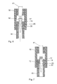
- the fastener magazine strip 10 has a carrier strip 11, which is composed of a plurality of sleeve-shaped carrier segments 12 integrally connected to one another.
- these carrier segments 12 are made of a plastic, such as. As polyethylene (PE), polypropylene (PP) or polystyrene (PS).
- PE polyethylene
- PP polypropylene
- PS polystyrene
- Each of the carrier segments 12 has in each case a receptacle formed as a through-opening 13, in each of which a fastening element 30 is mounted.
- the carrier segments 12 extend along a longitudinal axis A and have at their two axial ends in each case a guide section 20 with a guide diameter D. Between the two guide portions 20, a peripheral recess 17 is provided on the outer circumference of the carrier segments 12.
- wing-like projections 14 protrude from the carrier strip 11 or the carrier segments 12 on both sides of the plane E.
- the projections 14 are arranged approximately centrally between the two guide portions 20 and extend from their attachment point 15 on the carrier segment 12 to its free end 16 over a length L. Perpendicular to the length L and parallel to the plane E, the projections further have a first Width B1 up.
- the projections 14 protrude in the radial direction (with respect to the longitudinal axis A) the guide diameter D by a projection U, which preferably corresponds to 0.15 to 0.7 times the guide diameter D.
- the projections 14 are elastically bendable in at least one direction transversely to their longitudinal extent with the length L, which is achieved in particular by their geometry.
- the length L of the projections 14 preferably corresponds to 2 to 8 times their first width B1. In the example shown, the length L corresponds to approximately 4 times its first width B1.
- a second width B2 extending in a direction perpendicular to the length L and perpendicular to the first width B1 is greater than the first width B1 but smaller than the length L.
- the fastener element magazine strip 10 is arranged in a magazine 50 of a tacker device by means of which the fastener elements (such as nails or bolts) assembled on the fastener element magazine strip 10 can be driven into a workpiece or component. From the tacker are in the FIGS. 4 and 5 only the pin guide 40 and a part of the drive piston 41 reproduced.
- a slide 51 acted upon by a transport spring 52 in the transport direction 61 is provided in the magazine 50.
- About the wing-like projections 14 of the fastener magazine strip 10 is guided on guide rails 54 of the magazine 50 safely and without jamming.
- these serve as points of engagement for a counter-slide 53. If the tacker is no longer used, it is possible to move the counter-slide 53 (for example, when the tacker is lifted off the conveyor 62) in a direction opposite to the transport direction 61 Workpiece or component) of the fastener magazine strips 10 are moved so that the uppermost fastener 30 is moved out of the axial projection of the bolt guide 40 out (see in particular Fig. 5 ).
- FIGS. 6 and 7 the pin guide 40 and a part of the drive piston 41 are reproduced by the tacker.
- a first fastener 30 of the fastener magazine strip 10 is located in Fig. 6 in position ready for setting in the bolt guide 40 or in its axial projection.
- the tacker was actuated, so that the driving piston 41 moves in the setting direction and thus a fastener 30 with carrier segment 12 from the carrier strip 11 shears. Due to their elasticity, the projections 14 can be folded completely into the recess 17. This leaves no disturbing remnants of the projections 14 in the magazine 50 or in the space in front of the bolt guide 40.
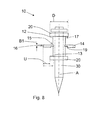
- the in Fig. 8 illustrated fastener magazine strips 10 differs from the previously described only in that the projections 14 in the region of the attachment points 15 each have a hinge 19 in the form of a reduced-thickness region of the projection 14.
- the length L preferably corresponds to 2 to 8 times the first width B1 in the region of the hinge 19. In the example shown corresponds to the Length L about 7.5 times its first width B1.
- the hinge 19 By the hinge 19, the elasticity or flexibility of the projections 14 in the region of the attachment point 15 is increased.
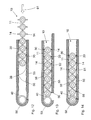
- FIGS. 9 to 14 a further fastener magazine strip 10 is shown, which differs from the previous one in that there are respectively arranged pairs 21 of projections 14 on the support segments 12 on both sides of the plane E.
- the projections 14 have an isometric geometry in cross section, ie the first width B1 is substantially equal to the second width B2.
- the length L of the projections 14 preferably corresponds to 2 to 8 times their first width B1. In the example shown, the length L corresponds to approximately 4.3 times its first width B1.
- one of the projections 14 of a pair 21 is arranged approximately centrally between the two guide portions 20, while the second projection 14 of a pair 21 is closer to a lying in the direction of the guide portion 20.
- the projections 14 in turn extend from their attachment point 15 on the support segment 12 to its free end 16 over a length L.
- Fig. 12 It is shown how the fastener magazine strip 10 is inserted in the direction of transport 61 in a magazine 50.
- a toothing 56 which cooperates with the projections 14 for transporting the fastening element magazine strip 10, is arranged in each case on the inside walls of the magazine 50.
- a wall section of the magazine 50 is designed as a transport rake 55 which is displaceable both in the transport direction 61 and in the exactly opposite direction 62.
- Fig. 13 is the fastener magazine strip 10 directly below the bolt guide 40 and their axial projection.
- the transport rake 55 is moved in a first transport movement in the opposite direction 62, wherein the toothing 56 of the transport rake 55 due to the elasticity of the projections 14 can be moved past them without moving the fastener magazine strip 10.
- the transport rake 55 does not itself have to be elastically supported in the direction perpendicular to the transport direction.
- fastener magazine strips 10 are moved in the transport direction 61 and a first Fastener 30 transported in the bolt guide 40 and at the level of the axial projection.
- the projections 14 can be folded completely into the recess 17 due to their elasticity. There remain no disturbing remnants of the projections 14 in the magazine 50 and in the space in front of the bolt guide 40th
- FIGS. 1 to 7 With regard to reference numerals not mentioned here, reference is made in full to the previous description of the drawings FIGS. 1 to 7 ,
Abstract
Description
Die vorliegende Erfindung betrifft einen Befestigungselemente-Magazinstreifen, der im Oberbegriff von Patentanspruch 1 genannten Art. Derartige Befestigungselemente-Magazinstreifen kommen z. B. in handgeführten Setzgeräten bzw. Eintreibgeräten zum Einsatz, mittels denen die an dem Befestigungselemente-Magazinstreifen magazinierten Befestigungselemente in ein Werkstück eingetrieben werden können.The present invention relates to a fastener magazine strip, the type mentioned in the preamble of claim 1. Such fastener magazine strips come z. As used in hand-held setting tools or tackers, by means of which the magazinierten on the fastener magazine strip fasteners can be driven into a workpiece.
Aus der
Bei diesem bekannten Befestigungselemente-Magazinstreifen müssen zur Führung der mit den Vorsprüngen versehenen Trägersegmente in einer Bolzenführung eines Setzgerätes in der Bolzenführung spezielle Führungsnuten für die Vorsprünge vorgesehen werden.In this known fastener magazine strips must be provided for guiding the carrier segments provided with the projections in a bolt guide of a setting tool in the bolt guide special guide grooves for the projections.
Die Aufgabe der vorliegenden Erfindung liegt daher darin, einen Befestigungselemente-Magazinstreifen bereitzustellen, welcher eine Zusatzfunktion ermöglicht und bei welchem die genannten Nachteile vermieden sind.The object of the present invention is therefore to provide a fastener magazine strip, which allows an additional function and in which the mentioned disadvantages are avoided.
Diese Aufgabe wird erfindungsgemäss durch die in Anspruch 1 genannten Massnahmen gelöst. Demnach sind die Vorsprünge in wenigstens einer Richtung quer zu ihrer Längserstreckung umbiegbar, vorzugsweise elastisch umbiegbar, ausgebildet, so dass die Vorsprünge im Bereich der Bolzenführung eines Eintreibgerätes bei einem Setzvorgang umklappen oder weggebogen werden können, ohne den Setzvorgang oder den Streifentransport zu behindern. Gesonderte Führungsnuten für die Vorsprünge an der Bolzenführung sind nicht mehr nötig.This object is achieved according to the invention by the measures mentioned in claim 1. Accordingly, the projections are bendable in at least one direction transversely to their longitudinal extension, preferably elastically bendable, designed so that the projections in the area of the pin guide of a tacker can fold over during a setting operation or be bent away without hindering the setting process or the strip transport. Separate guide grooves for the projections on the bolt guide are no longer necessary.
Vorteilhaft sind die Vorsprünge an den Trägersegmenten angeordnet, wobei am Aussenumfang der Trägersegmente jeweils wenigstens eine Ausnehmung vorgesehen ist, in welche die Vorsprünge hineinklappbar sind. Wenn ein Trägersegment bei einem Eintreibvorgang vom Befestigungselemente-Magazinstreifen abgeschert wird und durch die Bolzenführung eines Eintreibgerätes geführt wird, können die Vorsprünge in die Ausnehmung einklappen und behindern die Bewegung des Trägersegments in der Bolzenführung nicht.Advantageously, the projections are arranged on the carrier segments, wherein in each case at least one recess is provided on the outer circumference of the carrier segments, in which the projections are hineininklappbar. When a carrier segment is sheared from the fastener magazine strip in a driving operation and guided by the bolt guide of a tacker, the projections can fold into the recess and do not hinder the movement of the support segment in the bolt guide.
Von Vorteil ist es ferner, wenn die Länge der Vorsprünge dem 2- bis 8-fachen ihrer ersten Breite entspricht, wodurch die elastische Biegsamkeit, insbesondere bei einem Trägerstreifen aus Kunststoff, schon durch die Geometrie der Vorsprünge hervorgerufen wird.It is also advantageous if the length of the projections corresponds to 2 to 8 times their first width, whereby the elastic flexibility, especially in the case of a carrier strip made of plastic, is already caused by the geometry of the projections.
Vorteilhaft sind an Ansatzstellen der Vorsprünge am Trägerstreifen elastische Scharniere ausgebildet, die für eine elastische Biegsamkeit sorgen und die technisch einfach (z. B. durch eine Materialverjüngung) zu erstellen sind.Elastic hinges are advantageously formed at attachment points of the projections on the carrier strip, which provide elastic flexibility and which are technically easy to create (eg, by material tapering).
Günstig ist es auch, wenn der radiale Überstand der Vorsprünge über dem Führungsdurchmesser wenigstens dem 0,15- bis 0,7-fachen des Führungsdurchmesser entspricht, wodurch zum einen eine sichere Führung an Führungsflächen des Magazins ermöglicht wird und zum anderen eine Zusatzfunktion, z. B. eine radial aussenliegende Angriffsfläche für eine Zahnung eines Transportrechens eines Magazins oder eine radial aussenliegende Angriffsfläche für einen Gegenschieber zum Transportschieber eines Magazins, ermöglicht wird.It is also favorable if the radial projection of the projections over the guide diameter corresponds to at least 0.15 to 0.7 times the guide diameter, whereby on the one hand a secure guidance on guide surfaces of the magazine is made possible and on the other an additional function, for. B. a radially outer engagement surface for a toothing of a Transportrechens a magazine or a radially outer surface attack surface for a counter-slide to the transport slide a magazine is possible.
Insbesondere für die Verwendung eines Befestigungselemente-Magazinstreifens in einem Magazin mit Rechentransport ist es von Vorteil, wenn die Vorsprünge an jeder Seite des Trägerstreifens jeweils in Paaren angeordnet sind.In particular, for the use of a fastener magazine strip in a magazine with data transfer, it is advantageous if the projections on each side of the carrier strip are arranged in pairs.
Weiter vorteilhaft sind die Vorsprünge im Querschnitt senkrecht zu ihrer Längserstreckung isometrisch ausgebildet, so dass sie in wenigstens zwei Richtungen senkrecht bzw. quer zu ihrer Längserstreckung elastisch biegbar sind. Die isometrische Ausgestaltung des Querschnitts muss sich dabei nicht über die gesamte Länge der Vorsprünge erstrecken, sondern kann z. B. auch auf das Scharnier oder einen bestimmten Bereich beschränkt sein.Further advantageously, the projections are formed isometrically in cross-section perpendicular to their longitudinal extension, so that they are elastically bendable in at least two directions perpendicular or transversely to its longitudinal extent. The isometric design of the cross section does not have to extend over the entire length of the projections, but z. B. also be limited to the hinge or a specific area.
In den Zeichnungen ist die Erfindung in mehreren Ausführungsbeispielen dargestellt.In the drawings, the invention is shown in several embodiments.
- Fig. 1Fig. 1
- einen erfindungsgemässen Befestigungselemente-Magazinstreifen in Seitenansicht,an inventive fastener magazine strip in side view,
- Fig. 2Fig. 2
-
ein Trägersegment mit darin aufgenommenem Befestigungselement in Ansicht in Richtung des Pfeils II aus
Fig. 1 ,a carrier segment with fastener received therein in view in the direction of arrow IIFig. 1 . - Fig. 3Fig. 3
-
ein Trägersegment mit darin aufgenommenem Befestigungselement in Ansicht in Richtung des Pfeils III aus
Fig. 2 ,a carrier segment with fastener received therein in view in the direction of arrow IIIFig. 2 . - Fig. 4Fig. 4
-
ein Magazin mit einem darin befindlichen Befestigungselemente-Magazinstreifen nach den
Figuren 1 bis 3 in einem ersten Zustand,a magazine with a fastener magazine strip located therein after theFIGS. 1 to 3 in a first state, - Fig. 5Fig. 5
-
das Magazin aus
Fig. 4 in einem zweiten Zustand,the magazine offFig. 4 in a second state, - Fig. 6Fig. 6
-
einen Schnitt durch das Magazin entlang der Linie VI - VI aus
Fig. 4 ,a section through the magazine along the line VI - VI offFig. 4 . - Fig. 7Fig. 7
-
einen Schnitt durch das Magazin analog zu
Fig. 6 , während eines Setzvorgangs,a section through the magazine analogous toFig. 6 during a setting process, - Fig. 8Fig. 8
-
einen weiteren Befestigungselemente-Magazinstreifen in einer Ansicht analog zu
Fig. 2 ,another fastener magazine strip in a view analogous toFig. 2 . - Fig. 9Fig. 9
- einen weiteren Befestigungselemente-Magazinstreifen in Seitenansicht,another fastener magazine strip in side view,
- Fig. 10Fig. 10
-
den Befestigungselemente-Magazinstreifen in Ansicht in Richtung des Pfeils X aus
Fig. 9 ,the fastener magazine strip in view in the direction of arrow X fromFig. 9 .
- Fig. 11Fig. 11
-
ein Trägersegment mit darin aufgenommenem Befestigungselement in Ansicht in Richtung des Pfeils XI aus
Fig. 9 ,a carrier segment with therein fastener in view in the direction of arrow XIFig. 9 . - Fig. 12Fig. 12
-
ein Magazin während des Einführens eines Befestigungselemente-Magazinstreifen nach den
Figuren 9 bis 11 in das Magazin,a magazine during insertion of a fastener magazine strip after theFIGS. 9 to 11 in the magazine, - Fig. 13Fig. 13
-
das Magazin aus
Fig. 12 während einer ersten Bewegung eines Transportrechens,the magazine offFig. 12 during a first movement of a transport bill, - Fig. 14Fig. 14
-
das Magazin aus
Fig. 12 während einer Transportbewegung des Transportrechens.the magazine offFig. 12 during a transport movement of the transport bill.
In den
Die Trägersegmente 12 verlaufen entlang einer Längsachse A und weisen an ihren beiden axialen Enden jeweils einen Führungsabschnitt 20 mit einem Führungsdurchmesser D auf. Zwischen den beiden Führungsabschnitten 20 ist am Aussenumfang der Trägersegmente 12 jeweils eine umlaufende Ausnehmung 17 vorgesehen.The
Im Bereich der Ausnehmung 17 ragen zu beiden Seiten der Ebene E flügelartige Vorsprünge 14 von dem Trägerstreifen 11 bzw. den Trägersegmenten 12 ab. Die Vorsprünge 14 sind ungefähr mittig zwischen den beiden Führungsabschnitten 20 angeordnet und erstrecken sich dabei von ihrer Ansatzstelle 15 am Trägersegment 12 bis zu ihrem freien Ende 16 über eine Länge L. Senkrecht zu der Länge L und parallel zur Ebene E weisen die Vorsprünge ferner eine erste Breite B1 auf. Die Vorsprünge 14 überragen in radialer Richtung (bezogen auf die Längsachse A) den Führungsdurchmesser D um einen Überstand U, der vorzugsweise dem 0,15- bis 0,7-fachen des Führungsdurchmesser D entsprichtIn the region of the
Die Vorsprünge 14 sind in wenigstens einer Richtung quer zu ihrer Längserstreckung mit der Länge L elastisch umbiegbar ausgebildet, was insbesondere über ihre Geometrie erreicht wird. Die Länge L der Vorsprünge 14 entspricht vorzugsweise dem 2- bis 8-fachen ihrer ersten Breite B1. Im dargestellten Beispiel entspricht die Länge L dem ca. 4-fachen ihrer ersten Breite B1. Eine zweite Breite B2, die in einer Richtung senkrecht zur Länge L und senkrecht zur ersten Breite B1 verläuft, ist grösser als die erste Breite B1, aber kleiner als die Länge L.The
In den
In den
Der in
In den
In
In
Bei einer Bewegung des Transportrechens 55 in Transportrichtung 61 wird Befestigungselemente-Magazinstreifen 10 in Transportrichtung 61 mitbewegt und ein erstes Befestigungselement 30 in die Bolzenführung 40 bzw. in Höhe deren Axialprojektion transportiert.During a movement of the
Bei einem Eintreibvorgang können die Vorsprünge 14 auf Grund ihrer Elastizität vollständig in die Ausnehmung 17 geklappt werden. Es verbleiben keine störenden Überreste der Vorsprünge 14 im Magazin 50 bzw. in dem Raum vor der Bolzenführung 40.In a driving operation, the
Bezüglich hier nicht erwähnter Bezugszeichen wird vollumfänglich Bezug genommen auf die vorhergehende Beschreibung zu den
Claims (7)
wobei die Trägersegmente (12) wenigstens einen Führungsabschnitt (20) mit einem Führungsdurchmesser (D) sowie Durchführöffnungen (13) aufweisen, in denen jeweils ein Befestigungselement (30) gelagert ist,
wobei von dem Trägerstreifen (11) zu wenigstens einer Seite einer durch den Trägerstreifen (11) definierten Ebene (E) Vorsprünge (14) abragen, welche sich von ihrer Ansatzstelle (15) am Trägerstreifen (11) bis zu ihrem freien Ende (16) über eine Länge (L) erstrecken und senkrecht zu der Länge (L) eine erste Breite (B1) aufweisen,
und wobei die Vorsprünge (14) in, bezogen auf die Längsachse (A), radialer Richtung den Führungsdurchmesser (D) überragen,
dadurch gekennzeichnet,
dass die Vorsprünge (14) in wenigstens einer Richtung quer zu ihrer Längserstreckung umbiegbar ausgebildet sind.Fastening element magazine strip with a carrier strip (11) made of plastic, formed by a plurality of carrier segments (12) connected to one another and extending along a longitudinal axis (A),
wherein the carrier segments (12) have at least one guide section (20) with a guide diameter (D) and through openings (13), in each of which a fastening element (30) is mounted,
wherein protrusions (14) protrude from the carrier strip (11) to at least one side of a plane (E) defined by the carrier strip (11), extending from its attachment point (15) on the carrier strip (11) to its free end (16). extend over a length (L) and have a first width (B1) perpendicular to the length (L),
and wherein the projections (14) project beyond the guide diameter (D) in the radial direction with respect to the longitudinal axis (A),
characterized,
in that the projections (14) are bendable transversely to their longitudinal extent in at least one direction.
Priority Applications (1)
| Application Number | Priority Date | Filing Date | Title |
|---|---|---|---|
| PL10155751T PL2233754T3 (en) | 2009-03-24 | 2010-03-08 | Attachment elements cartridge strip |
Applications Claiming Priority (1)
| Application Number | Priority Date | Filing Date | Title |
|---|---|---|---|
| DE102009001790.9A DE102009001790B4 (en) | 2009-03-24 | 2009-03-24 | Fasteners magazine strip |
Publications (2)
| Publication Number | Publication Date |
|---|---|
| EP2233754A1 true EP2233754A1 (en) | 2010-09-29 |
| EP2233754B1 EP2233754B1 (en) | 2015-11-04 |
Family
ID=42321078
Family Applications (1)
| Application Number | Title | Priority Date | Filing Date |
|---|---|---|---|
| EP10155751.0A Active EP2233754B1 (en) | 2009-03-24 | 2010-03-08 | Attachment elements cartridge strip |
Country Status (11)
| Country | Link |
|---|---|
| US (1) | US8328012B2 (en) |
| EP (1) | EP2233754B1 (en) |
| JP (1) | JP5632174B2 (en) |
| CN (1) | CN101844344B (en) |
| BR (1) | BRPI1002101B1 (en) |
| CA (1) | CA2697575C (en) |
| DE (1) | DE102009001790B4 (en) |
| DK (1) | DK2233754T3 (en) |
| ES (1) | ES2561213T3 (en) |
| HU (1) | HUE028599T2 (en) |
| PL (1) | PL2233754T3 (en) |
Families Citing this family (5)
| Publication number | Priority date | Publication date | Assignee | Title |
|---|---|---|---|---|
| WO2014093986A2 (en) * | 2012-12-14 | 2014-06-19 | Ssp Fittings Corp. | System including cartridge, catridge feed system, pre-swaging assembly, tube bender, cutting and deburring station, and air blower/ vacuum chip collector |
| US9796072B2 (en) * | 2013-08-30 | 2017-10-24 | Illinois Tool Works Inc. | Staple tool |
| EP3335836A1 (en) * | 2016-12-15 | 2018-06-20 | HILTI Aktiengesellschaft | Driving device and fixing element strips |
| CN106985043A (en) * | 2017-03-21 | 2017-07-28 | 平湖福达五金制品有限公司 | A kind of magnet door-inhale hinge grooving apparatus |
| JP7192491B2 (en) * | 2018-12-27 | 2022-12-20 | マックス株式会社 | interlocking fastener |
Citations (4)
| Publication number | Priority date | Publication date | Assignee | Title |
|---|---|---|---|---|
| EP0336089A1 (en) * | 1988-03-02 | 1989-10-11 | HILTI Aktiengesellschaft | Carrier strip |
| US5984096A (en) * | 1996-09-24 | 1999-11-16 | Yugenkaisha Shinjo Seisakusho | Belt for holding and carrying a row of self-drilling ream screws |
| US20040042875A1 (en) * | 2002-09-03 | 2004-03-04 | Shu-Chung Huang | Screw strip with flanges at two sides |
| US20080121678A1 (en) | 2006-11-27 | 2008-05-29 | Robert Spasov | Hand-held drive-in tool |
Family Cites Families (12)
| Publication number | Priority date | Publication date | Assignee | Title |
|---|---|---|---|---|
| FR1600417A (en) * | 1968-08-05 | 1970-07-27 | ||
| JPS57136010U (en) * | 1981-02-20 | 1982-08-25 | ||
| DE3806626C2 (en) * | 1988-03-02 | 1997-04-24 | Hilti Ag | Powder-powered setting tool |
| US5803691A (en) * | 1997-06-09 | 1998-09-08 | Huang; Shih Chang | Strip for supporting nails |
| US5931622A (en) * | 1997-10-07 | 1999-08-03 | Illinois Tool Works Inc. | Fastener assembly with lateral end extension |
| US6679415B1 (en) * | 2002-08-05 | 2004-01-20 | Illinois Tool Works Inc. | Fastener collation strip having magazine rail-engaging members defining point-contact tip regions |
| US7021462B2 (en) * | 2002-12-18 | 2006-04-04 | Powers Fasteners, Inc. | Fastener carrier assembly and method of use |
| FR2850895B1 (en) * | 2003-02-10 | 2006-03-03 | Prospection & Inventions | BAND OF FIXING ELEMENTS FOR SEALING APPARATUS WITH CHARGER FOR RECEIVING THE BAND, THE APPARATUS AND THE CHARGER |
| JP4418200B2 (en) * | 2003-09-19 | 2010-02-17 | 日本パワーファスニング株式会社 | Connecting fastener and fastener holder |
| ATE405752T1 (en) * | 2004-06-24 | 2008-09-15 | Neumatica De Calvado Compania | BAND FOR CONVEYING NAILS OR OTHER FASTENING ELEMENTS |
| US7735577B2 (en) * | 2005-09-20 | 2010-06-15 | Power Products Iii, Llc | Carrier strip system and method for different diameter fasteners |
| DE102007000453A1 (en) * | 2007-08-20 | 2009-02-26 | Hilti Aktiengesellschaft | Changeable tool holder |
-
2009
- 2009-03-24 DE DE102009001790.9A patent/DE102009001790B4/en active Active
-
2010
- 2010-03-08 DK DK10155751.0T patent/DK2233754T3/en active
- 2010-03-08 PL PL10155751T patent/PL2233754T3/en unknown
- 2010-03-08 HU HUE10155751A patent/HUE028599T2/en unknown
- 2010-03-08 ES ES10155751.0T patent/ES2561213T3/en active Active
- 2010-03-08 EP EP10155751.0A patent/EP2233754B1/en active Active
- 2010-03-18 JP JP2010063290A patent/JP5632174B2/en active Active
- 2010-03-23 CA CA2697575A patent/CA2697575C/en active Active
- 2010-03-23 BR BRPI1002101-9 patent/BRPI1002101B1/en active IP Right Grant
- 2010-03-23 CN CN201010150715.7A patent/CN101844344B/en active Active
- 2010-03-23 US US12/730,096 patent/US8328012B2/en active Active
Patent Citations (4)
| Publication number | Priority date | Publication date | Assignee | Title |
|---|---|---|---|---|
| EP0336089A1 (en) * | 1988-03-02 | 1989-10-11 | HILTI Aktiengesellschaft | Carrier strip |
| US5984096A (en) * | 1996-09-24 | 1999-11-16 | Yugenkaisha Shinjo Seisakusho | Belt for holding and carrying a row of self-drilling ream screws |
| US20040042875A1 (en) * | 2002-09-03 | 2004-03-04 | Shu-Chung Huang | Screw strip with flanges at two sides |
| US20080121678A1 (en) | 2006-11-27 | 2008-05-29 | Robert Spasov | Hand-held drive-in tool |
Also Published As
| Publication number | Publication date |
|---|---|
| DK2233754T3 (en) | 2016-02-15 |
| US20100243703A1 (en) | 2010-09-30 |
| PL2233754T3 (en) | 2016-04-29 |
| HUE028599T2 (en) | 2016-12-28 |
| US8328012B2 (en) | 2012-12-11 |
| JP5632174B2 (en) | 2014-11-26 |
| CA2697575A1 (en) | 2010-09-24 |
| DE102009001790B4 (en) | 2014-01-16 |
| CA2697575C (en) | 2019-07-02 |
| ES2561213T3 (en) | 2016-02-25 |
| JP2010223431A (en) | 2010-10-07 |
| CN101844344A (en) | 2010-09-29 |
| DE102009001790A1 (en) | 2010-10-14 |
| BRPI1002101B1 (en) | 2019-11-26 |
| CN101844344B (en) | 2014-12-24 |
| BRPI1002101A2 (en) | 2011-07-26 |
| EP2233754B1 (en) | 2015-11-04 |
Similar Documents
| Publication | Publication Date | Title |
|---|---|---|
| EP1591693B1 (en) | Method and device for the storage of a thrust chain | |
| EP1925866B1 (en) | Plastic clamp | |
| EP2233754B1 (en) | Attachment elements cartridge strip | |
| DE3824894A1 (en) | DEVICE ON HAND MACHINE TOOLS FOR TORQUE TRANSMISSION | |
| DE10107887B4 (en) | setting tool | |
| EP3044475B1 (en) | Synchronous belt with belt fastener | |
| EP0972951B1 (en) | Setting device having nail magazine | |
| EP0274085B1 (en) | Plastic paper clip | |
| DE69735867T2 (en) | Enhanced earless clip with a flat profile | |
| EP2512851B1 (en) | Joining ends of weatherstrip | |
| EP3684715B1 (en) | Chain link, chain, chain conveyor and its use | |
| EP2691030B1 (en) | Surgical clip applicator | |
| DE202006006412U1 (en) | Coupling element for joining segments of cover for moving machine parts, comprising corner areas with elastic effect | |
| EP0972952B1 (en) | Nail magazin | |
| CH605042A5 (en) | Automatic fastener feed magazine | |
| EP0555655B1 (en) | Dust bag with closure device | |
| DE4222175A1 (en) | Rolling cage | |
| DE102010029051A1 (en) | Stop arrangement for attaching rear flap opposite to body part in vehicle, has adjustment element adapted to adjust pretensioning length of stop element in variable lateral layer along stop direction of stop element | |
| DE102008044368B3 (en) | Fastening element-magazine strip for e.g. tacker, has annular section axially lying outside of radial projection of casing-shaped section and comprising ring axis running parallel to cylindrical axis of casing-shaped section | |
| DE3109511A1 (en) | GUIDE RAIL FOR A CHAINSAW | |
| EP1013382B1 (en) | Cartridge magazine | |
| DE3138530C2 (en) | Connecting device | |
| DE10336872B3 (en) | magazine strip | |
| DE102005028603A1 (en) | Magazine soil device for e.g. pistol, has cavity retaining spring platform and parts of magazine spring, where platform is reprocatingly movable inside of magazine floor arrangement in expansion direction of magazine spring | |
| DE202013101787U1 (en) | Slide Rail |
Legal Events
| Date | Code | Title | Description |
|---|---|---|---|
| PUAI | Public reference made under article 153(3) epc to a published international application that has entered the european phase |
Free format text: ORIGINAL CODE: 0009012 |
|
| AK | Designated contracting states |
Kind code of ref document: A1 Designated state(s): AT BE BG CH CY CZ DE DK EE ES FI FR GB GR HR HU IE IS IT LI LT LU LV MC MK MT NL NO PL PT RO SE SI SK SM TR |
|
| AX | Request for extension of the european patent |
Extension state: AL BA ME RS |
|
| 17P | Request for examination filed |
Effective date: 20110329 |
|
| 17Q | First examination report despatched |
Effective date: 20120605 |
|
| GRAJ | Information related to disapproval of communication of intention to grant by the applicant or resumption of examination proceedings by the epo deleted |
Free format text: ORIGINAL CODE: EPIDOSDIGR1 |
|
| GRAP | Despatch of communication of intention to grant a patent |
Free format text: ORIGINAL CODE: EPIDOSNIGR1 |
|
| INTG | Intention to grant announced |
Effective date: 20150601 |
|
| RAP1 | Party data changed (applicant data changed or rights of an application transferred) |
Owner name: HILTI AKTIENGESELLSCHAFT |
|
| GRAS | Grant fee paid |
Free format text: ORIGINAL CODE: EPIDOSNIGR3 |
|
| GRAA | (expected) grant |
Free format text: ORIGINAL CODE: 0009210 |
|
| AK | Designated contracting states |
Kind code of ref document: B1 Designated state(s): AT BE BG CH CY CZ DE DK EE ES FI FR GB GR HR HU IE IS IT LI LT LU LV MC MK MT NL NO PL PT RO SE SI SK SM TR |
|
| REG | Reference to a national code |
Ref country code: GB Ref legal event code: FG4D Free format text: NOT ENGLISH |
|
| REG | Reference to a national code |
Ref country code: CH Ref legal event code: EP |
|
| REG | Reference to a national code |
Ref country code: AT Ref legal event code: REF Ref document number: 759410 Country of ref document: AT Kind code of ref document: T Effective date: 20151115 |
|
| REG | Reference to a national code |
Ref country code: IE Ref legal event code: FG4D Free format text: LANGUAGE OF EP DOCUMENT: GERMAN |
|
| REG | Reference to a national code |
Ref country code: DE Ref legal event code: R096 Ref document number: 502010010571 Country of ref document: DE |
|
| REG | Reference to a national code |
Ref country code: DK Ref legal event code: T3 Effective date: 20160208 |
|
| REG | Reference to a national code |
Ref country code: SE Ref legal event code: TRGR Ref country code: FR Ref legal event code: PLFP Year of fee payment: 7 |
|
| REG | Reference to a national code |
Ref country code: ES Ref legal event code: FG2A Ref document number: 2561213 Country of ref document: ES Kind code of ref document: T3 Effective date: 20160225 |
|
| REG | Reference to a national code |
Ref country code: LT Ref legal event code: MG4D |
|
| REG | Reference to a national code |
Ref country code: NO Ref legal event code: T2 Effective date: 20151104 |
|
| REG | Reference to a national code |
Ref country code: NL Ref legal event code: FP |
|
| PG25 | Lapsed in a contracting state [announced via postgrant information from national office to epo] |
Ref country code: HR Free format text: LAPSE BECAUSE OF FAILURE TO SUBMIT A TRANSLATION OF THE DESCRIPTION OR TO PAY THE FEE WITHIN THE PRESCRIBED TIME-LIMIT Effective date: 20151104 Ref country code: IS Free format text: LAPSE BECAUSE OF FAILURE TO SUBMIT A TRANSLATION OF THE DESCRIPTION OR TO PAY THE FEE WITHIN THE PRESCRIBED TIME-LIMIT Effective date: 20160304 Ref country code: LT Free format text: LAPSE BECAUSE OF FAILURE TO SUBMIT A TRANSLATION OF THE DESCRIPTION OR TO PAY THE FEE WITHIN THE PRESCRIBED TIME-LIMIT Effective date: 20151104 |
|
| PG25 | Lapsed in a contracting state [announced via postgrant information from national office to epo] |
Ref country code: LV Free format text: LAPSE BECAUSE OF FAILURE TO SUBMIT A TRANSLATION OF THE DESCRIPTION OR TO PAY THE FEE WITHIN THE PRESCRIBED TIME-LIMIT Effective date: 20151104 Ref country code: GR Free format text: LAPSE BECAUSE OF FAILURE TO SUBMIT A TRANSLATION OF THE DESCRIPTION OR TO PAY THE FEE WITHIN THE PRESCRIBED TIME-LIMIT Effective date: 20160205 Ref country code: PT Free format text: LAPSE BECAUSE OF FAILURE TO SUBMIT A TRANSLATION OF THE DESCRIPTION OR TO PAY THE FEE WITHIN THE PRESCRIBED TIME-LIMIT Effective date: 20160304 |
|
| REG | Reference to a national code |
Ref country code: DE Ref legal event code: R097 Ref document number: 502010010571 Country of ref document: DE |
|
| PG25 | Lapsed in a contracting state [announced via postgrant information from national office to epo] |
Ref country code: RO Free format text: LAPSE BECAUSE OF FAILURE TO SUBMIT A TRANSLATION OF THE DESCRIPTION OR TO PAY THE FEE WITHIN THE PRESCRIBED TIME-LIMIT Effective date: 20151104 Ref country code: EE Free format text: LAPSE BECAUSE OF FAILURE TO SUBMIT A TRANSLATION OF THE DESCRIPTION OR TO PAY THE FEE WITHIN THE PRESCRIBED TIME-LIMIT Effective date: 20151104 Ref country code: SM Free format text: LAPSE BECAUSE OF FAILURE TO SUBMIT A TRANSLATION OF THE DESCRIPTION OR TO PAY THE FEE WITHIN THE PRESCRIBED TIME-LIMIT Effective date: 20151104 |
|
| REG | Reference to a national code |
Ref country code: SK Ref legal event code: T3 Ref document number: E 21010 Country of ref document: SK |
|
| PLBE | No opposition filed within time limit |
Free format text: ORIGINAL CODE: 0009261 |
|
| STAA | Information on the status of an ep patent application or granted ep patent |
Free format text: STATUS: NO OPPOSITION FILED WITHIN TIME LIMIT |
|
| 26N | No opposition filed |
Effective date: 20160805 |
|
| PG25 | Lapsed in a contracting state [announced via postgrant information from national office to epo] |
Ref country code: LU Free format text: LAPSE BECAUSE OF FAILURE TO SUBMIT A TRANSLATION OF THE DESCRIPTION OR TO PAY THE FEE WITHIN THE PRESCRIBED TIME-LIMIT Effective date: 20160308 Ref country code: MC Free format text: LAPSE BECAUSE OF FAILURE TO SUBMIT A TRANSLATION OF THE DESCRIPTION OR TO PAY THE FEE WITHIN THE PRESCRIBED TIME-LIMIT Effective date: 20151104 |
|
| PG25 | Lapsed in a contracting state [announced via postgrant information from national office to epo] |
Ref country code: SI Free format text: LAPSE BECAUSE OF FAILURE TO SUBMIT A TRANSLATION OF THE DESCRIPTION OR TO PAY THE FEE WITHIN THE PRESCRIBED TIME-LIMIT Effective date: 20151104 |
|
| REG | Reference to a national code |
Ref country code: HU Ref legal event code: AG4A Ref document number: E028599 Country of ref document: HU |
|
| REG | Reference to a national code |
Ref country code: FR Ref legal event code: PLFP Year of fee payment: 8 |
|
| PG25 | Lapsed in a contracting state [announced via postgrant information from national office to epo] |
Ref country code: MT Free format text: LAPSE BECAUSE OF FAILURE TO SUBMIT A TRANSLATION OF THE DESCRIPTION OR TO PAY THE FEE WITHIN THE PRESCRIBED TIME-LIMIT Effective date: 20151104 |
|
| REG | Reference to a national code |
Ref country code: FR Ref legal event code: PLFP Year of fee payment: 9 |
|
| PG25 | Lapsed in a contracting state [announced via postgrant information from national office to epo] |
Ref country code: CY Free format text: LAPSE BECAUSE OF FAILURE TO SUBMIT A TRANSLATION OF THE DESCRIPTION OR TO PAY THE FEE WITHIN THE PRESCRIBED TIME-LIMIT Effective date: 20151104 |
|
| PG25 | Lapsed in a contracting state [announced via postgrant information from national office to epo] |
Ref country code: MK Free format text: LAPSE BECAUSE OF FAILURE TO SUBMIT A TRANSLATION OF THE DESCRIPTION OR TO PAY THE FEE WITHIN THE PRESCRIBED TIME-LIMIT Effective date: 20151104 |
|
| PG25 | Lapsed in a contracting state [announced via postgrant information from national office to epo] |
Ref country code: BG Free format text: LAPSE BECAUSE OF FAILURE TO SUBMIT A TRANSLATION OF THE DESCRIPTION OR TO PAY THE FEE WITHIN THE PRESCRIBED TIME-LIMIT Effective date: 20151104 |
|
| PGFP | Annual fee paid to national office [announced via postgrant information from national office to epo] |
Ref country code: NO Payment date: 20230324 Year of fee payment: 14 Ref country code: IE Payment date: 20230323 Year of fee payment: 14 Ref country code: FR Payment date: 20230322 Year of fee payment: 14 Ref country code: FI Payment date: 20230321 Year of fee payment: 14 Ref country code: DK Payment date: 20230323 Year of fee payment: 14 Ref country code: CZ Payment date: 20230228 Year of fee payment: 14 Ref country code: AT Payment date: 20230322 Year of fee payment: 14 |
|
| PGFP | Annual fee paid to national office [announced via postgrant information from national office to epo] |
Ref country code: TR Payment date: 20230306 Year of fee payment: 14 Ref country code: SK Payment date: 20230303 Year of fee payment: 14 Ref country code: SE Payment date: 20230314 Year of fee payment: 14 Ref country code: PL Payment date: 20230224 Year of fee payment: 14 Ref country code: HU Payment date: 20230323 Year of fee payment: 14 Ref country code: GB Payment date: 20230321 Year of fee payment: 14 Ref country code: DE Payment date: 20230321 Year of fee payment: 14 Ref country code: BE Payment date: 20230321 Year of fee payment: 14 |
|
| PGFP | Annual fee paid to national office [announced via postgrant information from national office to epo] |
Ref country code: NL Payment date: 20230321 Year of fee payment: 14 |
|
| PGFP | Annual fee paid to national office [announced via postgrant information from national office to epo] |
Ref country code: IT Payment date: 20230328 Year of fee payment: 14 Ref country code: ES Payment date: 20230529 Year of fee payment: 14 Ref country code: CH Payment date: 20230402 Year of fee payment: 14 |
|
| PGFP | Annual fee paid to national office [announced via postgrant information from national office to epo] |
Ref country code: IE Payment date: 20240321 Year of fee payment: 15 Ref country code: NL Payment date: 20240320 Year of fee payment: 15 |