EP2233211A1 - Push button for a pressurised liquid distribution system - Google Patents
Push button for a pressurised liquid distribution system Download PDFInfo
- Publication number
- EP2233211A1 EP2233211A1 EP10290139A EP10290139A EP2233211A1 EP 2233211 A1 EP2233211 A1 EP 2233211A1 EP 10290139 A EP10290139 A EP 10290139A EP 10290139 A EP10290139 A EP 10290139A EP 2233211 A1 EP2233211 A1 EP 2233211A1
- Authority
- EP
- European Patent Office
- Prior art keywords
- channels
- downstream
- upstream
- push button
- distribution
- Prior art date
- Legal status (The legal status is an assumption and is not a legal conclusion. Google has not performed a legal analysis and makes no representation as to the accuracy of the status listed.)
- Granted
Links
Images


Classifications
-
- B—PERFORMING OPERATIONS; TRANSPORTING
- B05—SPRAYING OR ATOMISING IN GENERAL; APPLYING FLUENT MATERIALS TO SURFACES, IN GENERAL
- B05B—SPRAYING APPARATUS; ATOMISING APPARATUS; NOZZLES
- B05B1/00—Nozzles, spray heads or other outlets, with or without auxiliary devices such as valves, heating means
- B05B1/26—Nozzles, spray heads or other outlets, with or without auxiliary devices such as valves, heating means with means for mechanically breaking-up or deflecting the jet after discharge, e.g. with fixed deflectors; Breaking-up the discharged liquid or other fluent material by impinging jets
-
- B—PERFORMING OPERATIONS; TRANSPORTING
- B05—SPRAYING OR ATOMISING IN GENERAL; APPLYING FLUENT MATERIALS TO SURFACES, IN GENERAL
- B05B—SPRAYING APPARATUS; ATOMISING APPARATUS; NOZZLES
- B05B11/00—Single-unit hand-held apparatus in which flow of contents is produced by the muscular force of the operator at the moment of use
- B05B11/01—Single-unit hand-held apparatus in which flow of contents is produced by the muscular force of the operator at the moment of use characterised by the means producing the flow
- B05B11/10—Pump arrangements for transferring the contents from the container to a pump chamber by a sucking effect and forcing the contents out through the dispensing nozzle
-
- B—PERFORMING OPERATIONS; TRANSPORTING
- B65—CONVEYING; PACKING; STORING; HANDLING THIN OR FILAMENTARY MATERIAL
- B65D—CONTAINERS FOR STORAGE OR TRANSPORT OF ARTICLES OR MATERIALS, e.g. BAGS, BARRELS, BOTTLES, BOXES, CANS, CARTONS, CRATES, DRUMS, JARS, TANKS, HOPPERS, FORWARDING CONTAINERS; ACCESSORIES, CLOSURES, OR FITTINGS THEREFOR; PACKAGING ELEMENTS; PACKAGES
- B65D83/00—Containers or packages with special means for dispensing contents
- B65D83/14—Containers or packages with special means for dispensing contents for delivery of liquid or semi-liquid contents by internal gaseous pressure, i.e. aerosol containers comprising propellant for a product delivered by a propellant
- B65D83/16—Containers or packages with special means for dispensing contents for delivery of liquid or semi-liquid contents by internal gaseous pressure, i.e. aerosol containers comprising propellant for a product delivered by a propellant characterised by the actuating means
- B65D83/20—Containers or packages with special means for dispensing contents for delivery of liquid or semi-liquid contents by internal gaseous pressure, i.e. aerosol containers comprising propellant for a product delivered by a propellant characterised by the actuating means operated by manual action, e.g. button-type actuator or actuator caps
Definitions
- the dispensing system is intended to equip bottles used in perfumery, in cosmetics or for pharmaceutical treatments.
- this type of bottle contains a liquid which is returned under pressure by a pump or a manually operated valve by means of a push button which is arranged to allow the spraying of the liquid.
- Such push buttons are conventionally made in two parts: an actuating body and a liquid spray nozzle which are associated with each other to form the push button.
- the spray nozzle may be arranged to form an aerosol with the liquid, in particular by defining a so-called vortex chamber.
- the vortex chamber is arranged to rotate very quickly the liquid to give it speed.
- the swirl chamber is extended at its center by a dispensing orifice, the liquid can escape at high speed by splitting into fine droplets forming the aerosol.
- the aerosol is composed of droplets of very different sizes.
- the aerosol is commonly constituted by droplets of diameter between 5 ⁇ m and 300 ⁇ m.
- the large droplets are heavier than the smaller ones and follow a different distribution path, which can cause indelible stains in the case of perfumes.
- the small droplets are the lightest and can be inhaled, which can be the goal sought in the case of drugs, but this can be an adverse effect in the case of toxic products.
- the place of application for example within the respiratory system, depends on the size of the droplets, and the large disparity in size distorts the treatment.
- the size of the droplets from a vortex chamber depends in part on the force and speed with which the user actuates the pump pressing the push button with his finger, because the induced pressure depends on it.
- the aerosol tends to be hollow with a substantially conical envelope which consists of the majority of the droplets while there is little to inside the cone.
- this distribution of droplets can be harmful for dermal applications.
- the document FR-2 903 328 proposes to use a non-swirling nozzle which is equipped with a micro-grid to ensure the calibration and the spatial distribution of the droplets.
- this embodiment requires sections of passages through the micro-grid which are extremely small, in particular of the order of 6 microns in diameter, which imposes a fine filtration of the liquid to avoid clogging problems.
- the difficulty of making and assembling in the body of these micro-grids remains high.
- a pushbutton comprising a distribution chamber which is provided with channels converging each towards an outlet orifice, said convergent channels being arranged to allow impaction of the liquid jets distributed by said orifices.
- the prior art proposes to equip the distribution chamber with an annular channel from which said convergent channels extend. This solution makes it possible to distribute the flows of liquid introduced into each channel but poses a certain number of problems.
- the liquid introduced under pressure into the annular duct becomes turbulent, which does not make it possible to stabilize the liquid flows introduced into the convergent channels.
- the speed of the flow of liquid introduced remains reduced, which, by limiting the impaction energy of the liquid jets distributed, does not allow the realization of an aerosol of optimum quality, particularly with regard to fineness, the calibration and the spatial distribution of the droplets composing it.
- the supply of the convergent conduits according to the prior art does not allow fractionation of the dose of liquid to be dispensed, that is to say, to restore only a portion of the dose provided by the pump.
- the support stroke of the push button is performed too rapidly, in particular of the order of 0.2 seconds per 100 .mu.l, to be interrupted by the user.
- the invention aims to solve the problems of the prior art by proposing in particular a push button for the distribution of an aerosol formed droplets having improved calibration and spatial distribution, and this by increasing the production time of said aerosol.
- the invention proposes a push button for a system for dispensing a liquid under pressure, said push button comprising a body on which a tip is mounted around an insert so as to form a distribution chamber between said tip and said insert, said distribution chamber being in communication with a conduit supply unit intended to be mounted on a pipe for supplying the pressurized liquid, said distribution chamber having, successively in communication, upstream channels, downstream channels and distribution channels, said distribution channels each converging towards an orifice output being arranged to allow the impingement of the liquid jets distributed by said orifices, the upstream and downstream channels extending longitudinally, forming a section respectively upstream and downstream of the circulation of the fluid in the distribution chamber, said downstream section having an average transverse area that is smaller than the average cross-sectional area of the upstream section.
- the invention proposes a system for dispensing a liquid under pressure, comprising a device for sampling under pressure of the liquid on which such a push button is mounted, the dispensing chamber being in communication with the tube of supplying the pressurized liquid from said sampling device so as to allow the liquid to be sprayed by impinging the jets from the distribution channels.
- a push button 1 is described below for a system for dispensing a pressurized liquid, said liquid being of any kind, especially used in perfumery, in cosmetics or for pharmaceutical treatments.
- the dispensing system also comprises a liquid-pressure sampling device 2 which is manually actuated by means of the push-button 1.
- the sampling device 2 may comprise a pump or a valve in the case where the liquid is conditioned under pressure.
- the push button 1 is mounted on a tube for supplying the pressurized liquid from the sampling device 2, the dispensing system being mounted on the neck of a bottle 3 containing the liquid so as to supply the push button 1 with said liquid under pressure.
- the push button 1 comprises a body having an annular skirt 4 which surrounds a housing 5 mounting on the tube for supplying the liquid under pressure.
- the push button 1 includes a zone upper 6 allowing the user to exert a digital support on said push button in order to move axially to actuate the sampling device 2.
- the push button 1 also comprises a tip 7 which is mounted around an insert 8 so as to form a distribution chamber between said tip and said insert.
- the body of the push button 1 has a housing 9 in which the insert 8 is arranged to allow lateral spraying of the liquid relative to the body of said push button.
- the insert 8 may be integral with the body of the pushbutton 1 ( figure 3a ) or be returned in slot 9 ( figures 3b , 8 ). Furthermore, the outer wall of the nozzle 7 has an anchoring rod 7a in the wall of the housing 9 so as to allow the association of said tip in said housing.
- the distribution chamber is in communication with a supply duct 10 whose upstream portion 10a opens into the mounting housing 5 on the tube for supplying the liquid under pressure.
- the upstream portion 10a is coaxial with the housing 5 and the supply duct 10 has a downstream portion 10b which is perpendicular to said housing.
- the downstream portion 10b may be of axis parallel to that of the upstream portion 10a.
- the distribution chamber presents, successively in communication, upstream channels 11, downstream channels 12 and distribution channels 13.
- the distribution channels 13 converge each towards an outlet orifice 14 being arranged to allow the impaction of the liquid jets distributed by said orifices.
- the distribution channels 13 can converge at a point C at an angle of the order of 70 °, so as to produce the aerosol A in the immediate vicinity of the outlet orifices 14.
- the upstream and downstream channels 11 and 12 are formed in the free space which is formed at the interface between an inner wall of the endpiece 7 and an outer wall of the insert 8, a recess being formed on at least one of said walls so as to be closed by the other wall delimiting said channels.
- the impression may be made hollow on one wall, the other wall has a complementary surface which radially closes said recesses so as to form the channels 11, 12 along said recesses.
- the recesses are formed on the outer wall of the insert 8 and the inner wall of the nozzle 7 is of revolution, however the reverse configuration is possible.
- the insert 8 has a base 15 on which extends a rod 16, the outer wall of said insert then comprising an upstream bearing 15a formed around said base and a downstream bearing 16a formed around said rod.
- the outside diameter of the upstream bearing surface 15a of the base 15 is greater than the outside diameter of the downstream bearing surface 16a of the rod 16.
- the inner wall of the nozzle 7 has an upstream surface 17 and a downstream surface 18 which are arranged opposite that of the insert 8 to form the respective upstream channels 11 and downstream 12 between them.
- the inside diameter of the upstream bearing surface 17 is greater than the inside diameter of the downstream bearing surface 18.
- upstream channels 11 extend longitudinally on the spans 15a, 16a forming respectively a section upstream and downstream of circulation of the fluid in the distribution chamber, said sections having a mean transverse surface which corresponds to the average of the transverse surfaces through which the fluid flows in the channels 11, 12.
- the transversal surface of upstream and downstream sections correspond to the sum of the transverse surfaces of the respectively upstream and downstream channels 11 and 12 respectively.
- the invention provides that the average cross-sectional area of the downstream section is smaller than the average cross-sectional area of the upstream section.
- the duration of distribution of a dose of liquid over the operating stroke of the push button 1 is increased.
- the duration of distribution for a dose of 100 ⁇ l can be between 0.5 and 2 seconds so as to allow the user to interrupt the dispensing of aerosol A during actuation.
- the upstream range 15a of the base 15 has flutes 19 which extend longitudinally in relief on the cylindrical surface of revolution of said span, an upstream channel 11 being formed between two flanks 19 adjacent.
- Each godron 19 has a central zone 19a whose outer diameter substantially corresponds to that of the upstream bearing 17 of the nozzle 7 so as to allow the centering and fitting of said tip on said gadroons.
- the base Upstream of the gadroons 19, the base has a cylindrical ring 20 around which an annular duct 21 of the distribution chamber is formed by being interposed between the downstream portion 10b of the supply duct 10 and the upstream channels 11. from the feed tube, the pressurized liquid passes into the supply conduit 10 to fill the annular conduit 21. Due to changes of direction, the flow of liquid is then turbulent and then passes into the upstream channels 11 within which it stabilizes and then accelerates in the downstream channels 12 before supplying the distribution channels 13.
- the downstream bearing surface 16a of the rod 16 has longitudinal grooves in which respectively a downstream channel 12 is formed, said grooves being in communication with the upstream channels 11.
- the gadroons 19 have a frustoconical downstream zone 19b which extends to the radial surface of junction between the base 15 and the rod 16, the complementary zone of the nozzle 7 being arranged to form an intermediate conduit 22 which is interposed between the upstream and downstream channels 11 and 12.
- the junction zone is annular so as to form an annular intermediate channel 22 into which the upstream and downstream channels 11 and 12 open.
- the tip 7 has material bridges 23 which are arranged to interrupt the annular channel so as to form a plurality of intermediate channels 22 of communication between the upstream channels 11 and downstream 12.
- the number of upstream channels 11 is different from that of downstream channels 12 since four upstream channels 11 communicate with three downstream channels 11. According to the first embodiment, the difference in cross-sectional area between the upstream and downstream sections is thus obtained. by providing more upstream channels 11 than downstream channels 12. As a variant of this embodiment, an identical number of upstream and downstream channels 11 and 11 can be formed and, as shown, the width of the upstream channels 11 is greater than that of the downstream channels. 12 so as to increase the speed of the liquid from upstream to downstream of the distribution chamber.
- the number of upstream channels 11 is equal to the number of downstream channels 12, each upstream channel 11 being in the longitudinal alignment of a downstream channel 12 so as to limit the pressure drop at the junction between these channels 11, 12 .
- the grooves of the rod 16 extend between the gadroons 19 and the difference in cross-sectional area between the section of the upstream and downstream channels 11 is obtained by a greater depth of the upstream channels 11.
- each downstream channel 12 has a frustoconical geometry which is arranged to form a distribution channel 13.
- the distribution channels 13, for example three in number, are very small, for example width about 60 microns and depth 70 microns for a device for sampling a dose of 100 .mu.l under a pressure of 5 bar.
- the endpiece 7 has a seat 24 pierced with an orifice 25 on which the end 26 of the rod 16 is mounted in abutment, said seat and said end each having a frustoconical geometry so as to form the distribution channels 13 and the outlets 14 between said geometries.
- the distribution channels 13 have a section whose transverse surface is decreasing from upstream to downstream.
- the upstream and downstream channels 11 and 12 are hollowed out on a cylindrical bearing surface of the tip 8, said bearing surface having an outer diameter corresponding substantially to that of an inner bearing 31 of the nozzle 7 so as to allow centering and forming the channels 11, 12 between said staves.
- the difference in average cross-sectional area between the section of the upstream and downstream channels 11 is obtained by providing that the downstream channels 12 have a variable width.
- the cross-sectional area of the downstream section is decreasing from the cross-sectional area of the section of the upstream channels 11 towards the cross-sectional area of the distribution channel section 13.
- the depth upstream channels 11 may also be greater than that of downstream channels 12 so as to further increase the difference in average cross-sectional area between the fluid flow section in said channels.
- span 30 has a cylindrical ring 20 around which the annular conduit 21 of the distribution chamber is formed.
- the tip 7 has a seat 24 pierced with an orifice 25 on which the end of the insert 8 mounted in abutment, said seat and said end each having a frustoconical geometry so as to form the distribution channels 13 and the outlets 14 between said geometries.
Landscapes
- Containers And Packaging Bodies Having A Special Means To Remove Contents (AREA)
Abstract
Description
Dans une application particulière, le système de distribution est destiné à équiper des flacons utilisés en parfumerie, en cosmétique ou pour des traitements pharmaceutiques. En effet, ce type de flacon contient un liquide qui est restitué sous pression par une pompe ou une valve à actionnement manuel au moyen d'un bouton poussoir qui est agencé pour permettre la pulvérisation du liquide.In a particular application, the dispensing system is intended to equip bottles used in perfumery, in cosmetics or for pharmaceutical treatments. Indeed, this type of bottle contains a liquid which is returned under pressure by a pump or a manually operated valve by means of a push button which is arranged to allow the spraying of the liquid.
De tels boutons poussoirs sont classiquement réalisés en deux parties : un corps d'actionnement et une buse de pulvérisation du liquide qui sont associés entre eux pour former le bouton poussoir. En particulier, la buse de pulvérisation peut être agencée pour former un aérosol avec le liquide, notamment en délimitant une chambre dite tourbillonnaire.Such push buttons are conventionally made in two parts: an actuating body and a liquid spray nozzle which are associated with each other to form the push button. In particular, the spray nozzle may be arranged to form an aerosol with the liquid, in particular by defining a so-called vortex chamber.
Pour ce faire, la chambre tourbillonnaire est agencée pour faire tourner très rapidement le liquide afin de lui donner de la vitesse. Ainsi, en prévoyant que la chambre tourbillonnaire soit prolongée en son centre par un orifice de distribution, le liquide peut s'échapper à forte vitesse en se fractionnant en fines gouttelettes formant l'aérosol.To do this, the vortex chamber is arranged to rotate very quickly the liquid to give it speed. Thus, by providing that the swirl chamber is extended at its center by a dispensing orifice, the liquid can escape at high speed by splitting into fine droplets forming the aerosol.
Toutefois, ce fractionnement se faisant de façon non maîtrisée, l'aérosol se trouve constitué de gouttelettes de tailles très variées. Par exemple, pour une pompe ou une valve alimentant un bouton poussoir par un flot d'alcool sous une pression de 5 bars, et un orifice de sortie de 0,3 mm, l'aérosol se trouve couramment constitué de gouttelettes de diamètre compris entre 5 µm et 300 µm.However, this fractionation being uncontrolled, the aerosol is composed of droplets of very different sizes. For example, for a pump or a valve supplying a push button with a flow of alcohol at a pressure of 5 bars, and an outlet orifice of 0.3 mm, the aerosol is commonly constituted by droplets of diameter between 5 μm and 300 μm.
Or, les grosses gouttelettes sont plus lourdes que les plus petites et suivent une trajectoire de distribution différente, pouvant provoquer des taches indélébiles dans le cas des parfums. Aussi, les petites gouttelettes sont les plus légères et peuvent être inhalées, ce qui peut être l'objectif recherché dans le cas de médicaments, mais ce qui peut être un effet indésirable dans le cas de produits toxiques. En outre, dans le cas des médicaments qui doivent être dispensés selon une posologie précise, le lieu d'application, par exemple à l'intérieur du système respiratoire, dépend de la taille des gouttelettes, et la grande disparité de tailles fausse le traitement.However, the large droplets are heavier than the smaller ones and follow a different distribution path, which can cause indelible stains in the case of perfumes. Also, the small droplets are the lightest and can be inhaled, which can be the goal sought in the case of drugs, but this can be an adverse effect in the case of toxic products. In addition, in the case of drugs that must be dispensed at a specific dosage, the place of application, for example within the respiratory system, depends on the size of the droplets, and the large disparity in size distorts the treatment.
Par ailleurs, la taille des gouttelettes issues d'une chambre tourbillonnaire dépend en partie de la force et de la vitesse avec laquelle l'utilisateur actionne la pompe en appuyant sur le bouton poussoir avec son doigt, car la pression induite en dépend.Furthermore, the size of the droplets from a vortex chamber depends in part on the force and speed with which the user actuates the pump pressing the push button with his finger, because the induced pressure depends on it.
En outre, notamment à cause des effets de la force centrifuge en sortie de la chambre tourbillonnaire, l'aérosol à tendance à être creux avec une enveloppe sensiblement conique qui est constituée de la majorité des gouttelettes alors qu'il y en a peu à l'intérieur du cône. En particulier, cette répartition des gouttelettes peut être dommageable pour les applications dermiques.In addition, particularly because of the effects of the centrifugal force at the outlet of the vortex chamber, the aerosol tends to be hollow with a substantially conical envelope which consists of the majority of the droplets while there is little to inside the cone. In particular, this distribution of droplets can be harmful for dermal applications.
Pour résoudre les problèmes mentionnés ci-dessus, notamment le document
Toutefois, cette réalisation nécessite des sections de passages à travers la micro-grille qui sont extrêmement petites, notamment de l'ordre de 6 µm de diamètre, ce qui impose une filtration fine du liquide afin d'éviter les problèmes de colmatage. En outre, la difficulté de réalisation et d'assemblage dans le corps de ces micro-grilles demeure élevée.However, this embodiment requires sections of passages through the micro-grid which are extremely small, in particular of the order of 6 microns in diameter, which imposes a fine filtration of the liquid to avoid clogging problems. In addition, the difficulty of making and assembling in the body of these micro-grids remains high.
On connaît par ailleurs, notamment du document
Pour alimenter en liquide les canaux convergents, l'art antérieur propose d'équiper la chambre de distribution d'un canal annulaire à partir duquel lesdits canaux convergents s'étendent. Cette solution permet de répartir les flux de liquide introduit dans chaque canal mais pose un certain nombre de problème.To supply liquid convergent channels, the prior art proposes to equip the distribution chamber with an annular channel from which said convergent channels extend. This solution makes it possible to distribute the flows of liquid introduced into each channel but poses a certain number of problems.
En particulier, le liquide introduit sous pression dans le conduit annulaire devient turbulent, ce qui ne permet pas de stabiliser les flux de liquide introduits dans les canaux convergents. En outre, la vitesse du flux de liquide introduit reste réduite, ce qui, en limitant l'énergie d'impaction des jets de liquide distribués, ne permet pas la réalisation d'un aérosol de qualité optimale, notamment relativement à la finesse, à la calibration et à la répartition spatiale des gouttelettes le composant.In particular, the liquid introduced under pressure into the annular duct becomes turbulent, which does not make it possible to stabilize the liquid flows introduced into the convergent channels. In addition, the speed of the flow of liquid introduced remains reduced, which, by limiting the impaction energy of the liquid jets distributed, does not allow the realization of an aerosol of optimum quality, particularly with regard to fineness, the calibration and the spatial distribution of the droplets composing it.
Par ailleurs, l'alimentation des conduits convergents selon l'art antérieur ne permet pas un fractionnement de la dose de liquide à distribuer, c'est-à-dire de ne restituer qu'une partie de la dose prévue par la pompe. En effet, la course d'appui du bouton poussoir est réalisée de façon trop rapide, notamment de l'ordre de 0,2 seconde pour 100 µl, pour pouvoir être interrompue par l'utilisateur.Furthermore, the supply of the convergent conduits according to the prior art does not allow fractionation of the dose of liquid to be dispensed, that is to say, to restore only a portion of the dose provided by the pump. Indeed, the support stroke of the push button is performed too rapidly, in particular of the order of 0.2 seconds per 100 .mu.l, to be interrupted by the user.
L'invention vise à résoudre les problèmes de l'art antérieur en proposant notamment un bouton poussoir permettant la distribution d'un aérosol formé de gouttelettes présentant une calibration et une répartition spatiale améliorées, et ce en augmentant la durée de production dudit aérosol.The invention aims to solve the problems of the prior art by proposing in particular a push button for the distribution of an aerosol formed droplets having improved calibration and spatial distribution, and this by increasing the production time of said aerosol.
A cet effet, et selon un premier aspect, l'invention propose un bouton poussoir pour un système de distribution d'un liquide sous pression, ledit bouton poussoir comprenant un corps sur lequel un embout est monté autour d'un insert de sorte à former une chambre de distribution entre ledit embout et ledit insert, ladite chambre de distribution étant en communication avec un conduit d'alimentation destiné à être monté sur un tube d'amenée du liquide sous pression, ladite chambre de distribution présentant, successivement en communication, des canaux amont, des canaux aval et des canaux de distribution, lesdits canaux de distribution convergeant chacun vers un orifice de sortie en étant agencés pour permettre l'impaction des jets de liquide distribués par lesdits orifices, les canaux amont et aval s'étendant longitudinalement en formant une section respectivement amont et aval de circulation du fluide dans la chambre de distribution, ladite section aval présentant une surface transversale moyenne qui est inférieure à la surface transversale moyenne de la section amont.For this purpose, and according to a first aspect, the invention proposes a push button for a system for dispensing a liquid under pressure, said push button comprising a body on which a tip is mounted around an insert so as to form a distribution chamber between said tip and said insert, said distribution chamber being in communication with a conduit supply unit intended to be mounted on a pipe for supplying the pressurized liquid, said distribution chamber having, successively in communication, upstream channels, downstream channels and distribution channels, said distribution channels each converging towards an orifice output being arranged to allow the impingement of the liquid jets distributed by said orifices, the upstream and downstream channels extending longitudinally, forming a section respectively upstream and downstream of the circulation of the fluid in the distribution chamber, said downstream section having an average transverse area that is smaller than the average cross-sectional area of the upstream section.
Selon un deuxième aspect, l'invention propose un système de distribution d'un liquide sous pression, comprenant un dispositif de prélèvement sous pression du liquide sur lequel un tel bouton poussoir est monté, la chambre de distribution étant en communication avec le tube d'amenée du liquide sous pression provenant dudit dispositif de prélèvement de sorte à permettre la pulvérisation du liquide par impaction des jets provenant des canaux de distribution.According to a second aspect, the invention proposes a system for dispensing a liquid under pressure, comprising a device for sampling under pressure of the liquid on which such a push button is mounted, the dispensing chamber being in communication with the tube of supplying the pressurized liquid from said sampling device so as to allow the liquid to be sprayed by impinging the jets from the distribution channels.
D'autres objets et avantages de l'invention apparaîtront dans la description qui suit, faite en référence aux figures annexées dans lesquelles :
- la
figure 1 est une vue partielle en perspective d'un système de distribution selon l'invention, ledit système étant monté sur le col d'un flacon ; - la
figure 2 est une vue agrandie de lafigure 1 montrant l'extrémité de distribution du bouton poussoir ; - les
figures 3 sont des vues en coupe longitudinale d'un bouton poussoir selon respectivement un mode de réalisation de l'invention, sur lesquelles est schématisée l'enveloppe du liquide distribué ; - la
figure 4 est une vue en perspective d'un insert selon un premier mode de réalisation de l'invention ; - les
figures 5 sont des vues d'un embout destiné à être monté autour de l'insert selon lafigure 4 , respectivement en coupe longitudinale (figure 5a ) et de dessous (figure 5b ) ; - la
figure 6 est une vue en perspective d'un insert selon un deuxième mode de réalisation de l'invention ; - les
figures 7 sont des vues d'un embout destiné à être monté autour de l'insert selon lafigure 6 , respectivement en coupe longitudinale (figure 7a ) et en coupe un quart (figure 7b ) ; - la
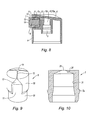
figure 8 est une vue en coupe longitudinale d'un bouton poussoir selon un autre mode de réalisation de l'invention ; - la
figure 9 est une vue en perspective de l'insert du bouton poussoir selon lafigure 8 ; - la
figure 10 est une vue en coupe longitudinale de l'embout destiné à être monté autour de l'insert selon lafigure 9 .
- the
figure 1 is a partial perspective view of a dispensing system according to the invention, said system being mounted on the neck of a bottle; - the
figure 2 is an enlarged view of thefigure 1 showing the dispensing end of the push button; - the
figures 3 are views in longitudinal section of a push button according to one embodiment of the invention, on which is schematized the envelope of the dispensed liquid; - the
figure 4 is a perspective view of an insert according to a first embodiment of the invention; - the
figures 5 are views of a tip intended to be mounted around the insert according to thefigure 4 , respectively in longitudinal section (figure 5a ) and from below (figure 5b ); - the
figure 6 is a perspective view of an insert according to a second embodiment of the invention; - the
figures 7 are views of a tip intended to be mounted around the insert according to thefigure 6 , respectively in longitudinal section (figure 7a ) and in quarter section (figure 7b ); - the
figure 8 is a longitudinal sectional view of a push button according to another embodiment of the invention; - the
figure 9 is a perspective view of the insert of the push button according to thefigure 8 ; - the
figure 10 is a longitudinal sectional view of the tip intended to be mounted around the insert according to thefigure 9 .
En relation avec les figures, on décrit ci-dessous un bouton poussoir 1 pour un système de distribution d'un liquide sous pression, ledit liquide pouvant être de toute nature, notamment utilisé en parfumerie, en cosmétique ou pour des traitements pharmaceutiques.In relation to the figures, a push button 1 is described below for a system for dispensing a pressurized liquid, said liquid being of any kind, especially used in perfumery, in cosmetics or for pharmaceutical treatments.
Le système de distribution comprend également un dispositif de prélèvement 2 sous pression du liquide qui est actionné manuellement au moyen du bouton poussoir 1. En particulier, le dispositif de prélèvement 2 peut comprendre une pompe ou une valve dans le cas où le liquide est conditionné sous pression.The dispensing system also comprises a liquid-
En relation avec la
Le bouton poussoir 1 comprend un corps présentant une jupe annulaire d'aspect 4 qui entoure un logement 5 de montage sur le tube d'amenée du liquide sous pression. Par ailleurs, le bouton poussoir 1 comprend une zone supérieure 6 permettant à l'utilisateur d'exercer un appui digital sur ledit bouton poussoir afin de pouvoir le déplacer axialement pour actionner le dispositif de prélèvement 2.The push button 1 comprises a body having an annular skirt 4 which surrounds a
Le bouton poussoir 1 comprend également un embout 7 qui est monté autour d'un insert 8 de sorte à former une chambre de distribution entre ledit embout et ledit insert. Dans les modes de réalisation représentés, le corps du bouton poussoir 1 présente un logement 9 dans lequel l'insert 8 est disposé pour permettre une pulvérisation latérale du liquide relativement au corps dudit bouton poussoir.The push button 1 also comprises a
L'insert 8 peut être venu de matière avec le corps du bouton poussoir 1 (
La chambre de distribution est en communication avec un conduit d'alimentation 10 dont la partie amont 10a débouche dans le logement 5 de montage sur le tube d'amenée du liquide sous pression. Dans les modes de réalisation représentés, la partie amont 10a est coaxiale au logement 5 et le conduit d'alimentation 10 présente une partie aval 10b qui est perpendiculaire audit logement. Selon une autre réalisation, par exemple pour un embout nasal, la partie aval 10b peut être d'axe parallèle à celui de la partie amont 10a.The distribution chamber is in communication with a supply duct 10 whose upstream portion 10a opens into the mounting
La chambre de distribution présente, successivement en communication, des canaux amont 11, des canaux aval 12 et des canaux de distribution 13. Pour permettre la pulvérisation du liquide en formant un aérosol, les canaux de distribution 13 convergent chacun vers un orifice de sortie 14 en étant agencés pour permettre l'impaction des jets de liquide distribués par lesdits orifices. En particulier, les canaux de distribution 13 peuvent converger en un point C suivant un angle de l'ordre de 70°, de sorte à produire l'aérosol A à proximité immédiate des orifices de sortie 14.The distribution chamber presents, successively in communication,
Sur les figures, les canaux amont 11 et aval 12 sont formés dans l'espace libre qui est formé à l'interface entre une paroi intérieure de l'embout 7 et une paroi extérieure de l'insert 8, une empreinte en creux étant formée sur au moins une desdites parois de sorte à être fermée par l'autre paroi en délimitant lesdits canaux.In the figures, the upstream and
En particulier, l'empreinte peut être réalisée en creux sur une paroi, l'autre paroi présente une surface complémentaire qui vient fermer radialement lesdits creux de sorte à former les canaux 11, 12 le long desdits creux. Dans les modes de réalisation représentés, les creux sont réalisés sur la paroi extérieure de l'insert 8 et la paroi intérieure de l'embout 7 est de révolution, toutefois la configuration inverse est envisageable.In particular, the impression may be made hollow on one wall, the other wall has a complementary surface which radially closes said recesses so as to form the
Sur les
De même, la paroi intérieure de l'embout 7 présente une portée amont 17 et une portée aval 18 qui sont disposées en regard de celle de l'insert 8 pour former les canaux respectivement amont 11 et aval 12 entre elles. En particulier, le diamètre intérieur de la portée amont 17 est supérieur au diamètre intérieur de la portée aval 18.Similarly, the inner wall of the
En relation avec les
L'invention prévoit que la surface transversale moyenne de la section aval soit inférieure à la surface transversale moyenne de la section amont. Ainsi, la vitesse du liquide augmente depuis l'amont vers l'aval de sorte à pouvoir alimenter les canaux convergents 13 avec un flux de liquide dont la vitesse est importante. Il en résulte une énergie d'impaction importante qui permet la réalisation d'un aérosol A formé d'une répartition spatiale uniforme de gouttelettes en suspension dans l'air, la taille desdites gouttelettes étant petite et uniforme. En particulier, l'aérosol A peut présenter alors l'aspect d'un panache de fumée.The invention provides that the average cross-sectional area of the downstream section is smaller than the average cross-sectional area of the upstream section. Thus, the speed of the liquid increases from upstream to downstream so as to feed the
En outre, du fait du passage du liquide dans une section aval qui est de surface transversale réduite par rapport à celle de la section amont, on augmente la durée de distribution d'une dose de liquide sur la course d'actionnement du bouton poussoir 1. En particulier, la durée de distribution pour une dose de 100 µl peut être comprise entre 0,5 et 2 secondes de sorte à laisser la possibilité à l'utilisateur d'interrompre la distribution de l'aérosol A en cours d'actionnement.In addition, because of the passage of the liquid in a downstream section which is of reduced transverse surface area compared to that of the upstream section, the duration of distribution of a dose of liquid over the operating stroke of the push button 1 is increased. In particular, the duration of distribution for a dose of 100 μl can be between 0.5 and 2 seconds so as to allow the user to interrupt the dispensing of aerosol A during actuation.
La portée amont 15a de la base 15 présente des godrons 19 qui s'étendent longitudinalement en relief sur la surface cylindrique de révolution de ladite portée, un canal amont 11 étant formé entre deux godrons 19 adjacents. Chaque godron 19 présente une zone centrale 19a dont le diamètre extérieur correspond sensiblement à celui de la portée amont 17 de l'embout 7 de sorte à permettre le centrage et l'emmanchement dudit embout sur lesdits godrons.The
En amont des godrons 19, la base présente une couronne cylindrique 20 autour de laquelle un conduit annulaire 21 de la chambre de distribution est formé en étant interposé entre la partie aval 10b du conduit d'alimentation 10 et les canaux amont 11. Ainsi, en provenant du tube d'amené, le liquide sous pression passe dans le conduit d'alimentation 10 pour remplir le conduit annulaire 21. A cause des changements de direction, le flot de liquide est alors turbulent et passe ensuite dans les canaux amont 11 à l'intérieur desquels il se stabilise puis s'accélère dans les canaux aval 12 avant d'alimenter les canaux de distribution 13.Upstream of the gadroons 19, the base has a
Par ailleurs, dans les modes de réalisation représentés, la portée aval 16a de la tige 16 présente des rainures longitudinales dans lesquelles respectivement un canal aval 12 est formé, lesdites rainures étant en communication avec les canaux amont 11.Moreover, in the embodiments shown, the
Dans le premier mode de réalisation (
En particulier, la zone de jonction est annulaire de sorte à pouvoir former un canal intermédiaire 22 annulaire dans lequel débouchent les canaux amont 11 et aval 12. Sur les
En outre, le nombre de canaux amont 11 est différent de celui des canaux aval 12 puisque quatre canaux amont 11 communiquent avec trois canaux aval 11. Selon le premier mode de réalisation, la différence de surface transversale entre les sections amont et aval est donc obtenue en prévoyant plus de canaux amont 11 que de canaux aval 12. En variante de cette réalisation, un nombre identique de canaux amont 11 et aval 12 peut être formé et, comme représenté, la largeur des canaux amont 11 est supérieure à celle des canaux aval 12 de sorte à augmenter la vitesse du liquide depuis l'amont vers l'aval de la chambre de distribution.In addition, the number of
Dans le deuxième mode de réalisation (
Pour ce faire, les rainures de la tige 16 s'étendent entre les godrons 19 et la différence de surface transversale entre la section des canaux amont 11 et aval 12 est obtenue par une profondeur plus importante des canaux amont 11.To do this, the grooves of the
Dans les modes de réalisation représentés, l'extrémité de chaque canal aval 12 présente une géométrie tronconique qui est agencée pour former un canal de distribution 13. Les canaux de distribution 13, par exemple au nombre de trois, sont très petits, par exemple de largeur environ 60 µm et de profondeur 70 µm pour un dispositif de prélèvement d'une dose de 100 µl sous une pression de 5 bars.In the embodiments shown, the end of each
Plus précisément, l'embout 7 présente un siège 24 percé d'un orifice 25 sur lequel l'extrémité 26 de la tige 16 est montée en appui, ledit siège et ladite extrémité présentant chacun une géométrie tronconique de sorte à former les canaux de distribution 13 et les orifices de sortie 14 entre lesdites géométries.More specifically, the
En outre, pour augmenter encore la vitesse des jets de liquide distribués par les orifices de sortie 14, on peut prévoir que les canaux de distribution 13 présentent une section dont la surface transversale est décroissante d'amont en aval.In addition, to further increase the speed of the liquid jets distributed by the outlet orifices 14, it can be provided that the
En relation avec les
Dans ce mode de réalisation, la différence de surface transversale moyenne entre la section des canaux amont 11 et aval 12 est obtenue en prévoyant que les canaux aval 12 présentent une largeur variable. En particulier, dans le mode de réalisation représenté, la surface transversale de la section aval est décroissante depuis la surface transversale de la section des canaux amont 11 vers la surface transversale de la section des canaux de distribution 13. En variante non représentée, la profondeur des canaux amont 11 peut en outre être supérieure à celle des canaux aval 12 de sorte à augmenter encore la différence de surface transversale moyenne entre la section de circulation du fluide dans lesdits canaux .In this embodiment, the difference in average cross-sectional area between the section of the upstream and
Par ailleurs, comme dans les modes de réalisation des
Claims (17)
Applications Claiming Priority (1)
| Application Number | Priority Date | Filing Date | Title |
|---|---|---|---|
| FR0901358A FR2943323B1 (en) | 2009-03-23 | 2009-03-23 | PUSH BUTTON FOR A PRESSURIZED LIQUID DISTRIBUTION SYSTEM |
Publications (2)
| Publication Number | Publication Date |
|---|---|
| EP2233211A1 true EP2233211A1 (en) | 2010-09-29 |
| EP2233211B1 EP2233211B1 (en) | 2014-11-26 |
Family
ID=40943667
Family Applications (1)
| Application Number | Title | Priority Date | Filing Date |
|---|---|---|---|
| EP10290139.4A Not-in-force EP2233211B1 (en) | 2009-03-23 | 2010-03-16 | Push button for a pressurised liquid distribution system |
Country Status (4)
| Country | Link |
|---|---|
| US (1) | US8528838B2 (en) |
| EP (1) | EP2233211B1 (en) |
| ES (1) | ES2530045T3 (en) |
| FR (1) | FR2943323B1 (en) |
Cited By (1)
| Publication number | Priority date | Publication date | Assignee | Title |
|---|---|---|---|---|
| WO2018041594A1 (en) * | 2016-09-02 | 2018-03-08 | Albea Le Treport | Pressurised fluid dispensing head and aerosol can or manual pump comprising such a dispensing head |
Families Citing this family (2)
| Publication number | Priority date | Publication date | Assignee | Title |
|---|---|---|---|---|
| WO2015138241A1 (en) * | 2014-03-10 | 2015-09-17 | Plastek Industries, Inc. | Modular spray cap |
| US20220361649A1 (en) * | 2021-05-13 | 2022-11-17 | RiViv, LLC | Drink container with sprayer and related methods |
Citations (4)
| Publication number | Priority date | Publication date | Assignee | Title |
|---|---|---|---|---|
| US20030230641A1 (en) * | 2002-06-12 | 2003-12-18 | Foster Donald D. | High viscosity liquid sprayer nozzle assembly |
| US20070051831A1 (en) * | 2005-09-02 | 2007-03-08 | Roy Kuo | Pump-dispensing atomizer |
| FR2903328A1 (en) | 2006-07-10 | 2008-01-11 | Rexam Dispensing Systems Sas | Manual spraying device for spraying e.g. pharmaceutical product, has set of calibrated holes, where diameter of each hole ranges between specific micrometers and does not differ from mean of diameters of other holes by specific percentage |
| FR2915470A1 (en) | 2007-04-24 | 2008-10-31 | Rexam Dispensing Systems Sas | Push button for use in e.g. liquid, distributor, has distribution interface defined by inner surface of female element and outer surface of male element, where passages are placed in interface and surfaces are in contact between passages |
Family Cites Families (4)
| Publication number | Priority date | Publication date | Assignee | Title |
|---|---|---|---|---|
| US4109869A (en) * | 1977-06-16 | 1978-08-29 | Dutton-Lainson Company | Oiler with adjustable spray nozzle |
| US4187985A (en) * | 1978-12-08 | 1980-02-12 | The Continental Group, Inc. | Aerosol valve for barrier type packages |
| US4991778A (en) * | 1989-11-16 | 1991-02-12 | Afa Products, Inc. | Adjustable nozzle assembly |
| US5779156A (en) * | 1995-11-13 | 1998-07-14 | Par-Way Group | Spray dispenser and system for spraying viscous liquids |
-
2009
- 2009-03-23 FR FR0901358A patent/FR2943323B1/en not_active Expired - Fee Related
-
2010
- 2010-03-16 EP EP10290139.4A patent/EP2233211B1/en not_active Not-in-force
- 2010-03-16 ES ES10290139.4T patent/ES2530045T3/en active Active
- 2010-03-22 US US12/728,731 patent/US8528838B2/en not_active Expired - Fee Related
Patent Citations (4)
| Publication number | Priority date | Publication date | Assignee | Title |
|---|---|---|---|---|
| US20030230641A1 (en) * | 2002-06-12 | 2003-12-18 | Foster Donald D. | High viscosity liquid sprayer nozzle assembly |
| US20070051831A1 (en) * | 2005-09-02 | 2007-03-08 | Roy Kuo | Pump-dispensing atomizer |
| FR2903328A1 (en) | 2006-07-10 | 2008-01-11 | Rexam Dispensing Systems Sas | Manual spraying device for spraying e.g. pharmaceutical product, has set of calibrated holes, where diameter of each hole ranges between specific micrometers and does not differ from mean of diameters of other holes by specific percentage |
| FR2915470A1 (en) | 2007-04-24 | 2008-10-31 | Rexam Dispensing Systems Sas | Push button for use in e.g. liquid, distributor, has distribution interface defined by inner surface of female element and outer surface of male element, where passages are placed in interface and surfaces are in contact between passages |
Cited By (2)
| Publication number | Priority date | Publication date | Assignee | Title |
|---|---|---|---|---|
| WO2018041594A1 (en) * | 2016-09-02 | 2018-03-08 | Albea Le Treport | Pressurised fluid dispensing head and aerosol can or manual pump comprising such a dispensing head |
| FR3055560A1 (en) * | 2016-09-02 | 2018-03-09 | Albea Le Treport | HEAD FOR DISPENSING A PRESSURIZED FLUID AND AEROSOL BOMB OR A MANUALLY ACTUATED PUMP COMPRISING SUCH A DISPENSING HEAD |
Also Published As
| Publication number | Publication date |
|---|---|
| US20100237172A1 (en) | 2010-09-23 |
| EP2233211B1 (en) | 2014-11-26 |
| ES2530045T3 (en) | 2015-02-26 |
| US8528838B2 (en) | 2013-09-10 |
| FR2943323A1 (en) | 2010-09-24 |
| FR2943323B1 (en) | 2011-06-10 |
Similar Documents
| Publication | Publication Date | Title |
|---|---|---|
| EP2496361B2 (en) | Pushbutton for a system for dispensing a pressurized substance | |
| EP0802827B1 (en) | Spray nozzle | |
| EP3231516B1 (en) | Spray nozzle, in particular for a system for dispensing a pressurized fluid provided with a pushbutton, and dispensing system comprising such a nozzle | |
| FR2903328A1 (en) | Manual spraying device for spraying e.g. pharmaceutical product, has set of calibrated holes, where diameter of each hole ranges between specific micrometers and does not differ from mean of diameters of other holes by specific percentage | |
| EP2606980B1 (en) | Push button for a system for pressurised product distribution | |
| FR2903329A1 (en) | SPRAY NOZZLE, SPRAY DEVICE AND USE THEREOF. | |
| FR2985202A1 (en) | HEAD OF DISTRIBUTION | |
| EP2006025A1 (en) | Spray nozzle comprising balanced axial intake grooves for the whirl chamber | |
| EP2119508B1 (en) | Push button for convergent distribution channels | |
| CA2048313C (en) | Integrated valve nozzle | |
| EP2233211B1 (en) | Push button for a pressurised liquid distribution system | |
| EP3479906A1 (en) | Spray nozzle with pre-atomisation narrowing, and spray head and spraying device comprising such a nozzle | |
| EP2258484B1 (en) | Push-button for a pressurised liquid distribution system | |
| WO2003061839A1 (en) | Atomisation nozzle with reduced diameter | |
| EP2353726B1 (en) | Push button for a system for pressurised product distribution | |
| EP2279795B1 (en) | System for dispensing a fluid product | |
| FR2927551A1 (en) | Fluid product e.g. perfume, spraying nozzle for dispenser, has supply conduit defined by internal and external edges in plane perpendicular to rotational axis, where external edge is not tangential to lateral surface of outlet channel | |
| EP3530355A1 (en) | Dispensing head with stepped whirl chamber for a dispensing system | |
| EP3261779B1 (en) | Pushbutton for a system for dispensing a product under pressure | |
| WO2023111470A1 (en) | Spraying head | |
| FR2990931A1 (en) | Delivery system for being mounted on container of bottle for distribution of lacquer utilized in e.g. pharmaceutical treatments, has air supply path including downstream end that emerges directly to spraying zone | |
| WO2018041594A1 (en) | Pressurised fluid dispensing head and aerosol can or manual pump comprising such a dispensing head | |
| FR3047235A1 (en) | PRESSURIZED CONTAINER WITH HOLLOW HEAD AND ADDITIONAL GAS VALVE | |
| FR2933883A1 (en) | Fluid product spraying device for use in e.g. perfumery field, has distribution wall comprising inner surface that is curved so as to define curvature direction, and spraying hole defining inner orifice extending in direction |
Legal Events
| Date | Code | Title | Description |
|---|---|---|---|
| PUAI | Public reference made under article 153(3) epc to a published international application that has entered the european phase |
Free format text: ORIGINAL CODE: 0009012 |
|
| AK | Designated contracting states |
Kind code of ref document: A1 Designated state(s): AT BE BG CH CY CZ DE DK EE ES FI FR GB GR HR HU IE IS IT LI LT LU LV MC MK MT NL NO PL PT RO SE SI SK SM TR |
|
| AX | Request for extension of the european patent |
Extension state: AL BA ME RS |
|
| 17P | Request for examination filed |
Effective date: 20110328 |
|
| 17Q | First examination report despatched |
Effective date: 20120813 |
|
| RAP1 | Party data changed (applicant data changed or rights of an application transferred) |
Owner name: ALBEA LE TREPORT |
|
| REG | Reference to a national code |
Ref country code: DE Ref legal event code: R079 Ref document number: 602010020502 Country of ref document: DE Free format text: PREVIOUS MAIN CLASS: B05B0001340000 Ipc: B05B0001260000 |
|
| RIC1 | Information provided on ipc code assigned before grant |
Ipc: B05B 1/26 20060101AFI20140602BHEP |
|
| GRAP | Despatch of communication of intention to grant a patent |
Free format text: ORIGINAL CODE: EPIDOSNIGR1 |
|
| INTG | Intention to grant announced |
Effective date: 20140807 |
|
| GRAS | Grant fee paid |
Free format text: ORIGINAL CODE: EPIDOSNIGR3 |
|
| GRAA | (expected) grant |
Free format text: ORIGINAL CODE: 0009210 |
|
| AK | Designated contracting states |
Kind code of ref document: B1 Designated state(s): AT BE BG CH CY CZ DE DK EE ES FI FR GB GR HR HU IE IS IT LI LT LU LV MC MK MT NL NO PL PT RO SE SI SK SM TR |
|
| REG | Reference to a national code |
Ref country code: GB Ref legal event code: FG4D Free format text: NOT ENGLISH |
|
| REG | Reference to a national code |
Ref country code: CH Ref legal event code: EP |
|
| REG | Reference to a national code |
Ref country code: AT Ref legal event code: REF Ref document number: 697864 Country of ref document: AT Kind code of ref document: T Effective date: 20141215 |
|
| REG | Reference to a national code |
Ref country code: IE Ref legal event code: FG4D Free format text: LANGUAGE OF EP DOCUMENT: FRENCH |
|
| REG | Reference to a national code |
Ref country code: DE Ref legal event code: R096 Ref document number: 602010020502 Country of ref document: DE Effective date: 20150108 |
|
| REG | Reference to a national code |
Ref country code: ES Ref legal event code: FG2A Ref document number: 2530045 Country of ref document: ES Kind code of ref document: T3 Effective date: 20150226 |
|
| REG | Reference to a national code |
Ref country code: FR Ref legal event code: PLFP Year of fee payment: 6 |
|
| REG | Reference to a national code |
Ref country code: NL Ref legal event code: VDEP Effective date: 20141126 |
|
| REG | Reference to a national code |
Ref country code: AT Ref legal event code: MK05 Ref document number: 697864 Country of ref document: AT Kind code of ref document: T Effective date: 20141126 |
|
| REG | Reference to a national code |
Ref country code: LT Ref legal event code: MG4D |
|
| PG25 | Lapsed in a contracting state [announced via postgrant information from national office to epo] |
Ref country code: IS Free format text: LAPSE BECAUSE OF FAILURE TO SUBMIT A TRANSLATION OF THE DESCRIPTION OR TO PAY THE FEE WITHIN THE PRESCRIBED TIME-LIMIT Effective date: 20150326 Ref country code: NO Free format text: LAPSE BECAUSE OF FAILURE TO SUBMIT A TRANSLATION OF THE DESCRIPTION OR TO PAY THE FEE WITHIN THE PRESCRIBED TIME-LIMIT Effective date: 20150226 Ref country code: FI Free format text: LAPSE BECAUSE OF FAILURE TO SUBMIT A TRANSLATION OF THE DESCRIPTION OR TO PAY THE FEE WITHIN THE PRESCRIBED TIME-LIMIT Effective date: 20141126 Ref country code: NL Free format text: LAPSE BECAUSE OF FAILURE TO SUBMIT A TRANSLATION OF THE DESCRIPTION OR TO PAY THE FEE WITHIN THE PRESCRIBED TIME-LIMIT Effective date: 20141126 Ref country code: LT Free format text: LAPSE BECAUSE OF FAILURE TO SUBMIT A TRANSLATION OF THE DESCRIPTION OR TO PAY THE FEE WITHIN THE PRESCRIBED TIME-LIMIT Effective date: 20141126 Ref country code: PT Free format text: LAPSE BECAUSE OF FAILURE TO SUBMIT A TRANSLATION OF THE DESCRIPTION OR TO PAY THE FEE WITHIN THE PRESCRIBED TIME-LIMIT Effective date: 20150326 |
|
| PG25 | Lapsed in a contracting state [announced via postgrant information from national office to epo] |
Ref country code: SE Free format text: LAPSE BECAUSE OF FAILURE TO SUBMIT A TRANSLATION OF THE DESCRIPTION OR TO PAY THE FEE WITHIN THE PRESCRIBED TIME-LIMIT Effective date: 20141126 Ref country code: LV Free format text: LAPSE BECAUSE OF FAILURE TO SUBMIT A TRANSLATION OF THE DESCRIPTION OR TO PAY THE FEE WITHIN THE PRESCRIBED TIME-LIMIT Effective date: 20141126 Ref country code: HR Free format text: LAPSE BECAUSE OF FAILURE TO SUBMIT A TRANSLATION OF THE DESCRIPTION OR TO PAY THE FEE WITHIN THE PRESCRIBED TIME-LIMIT Effective date: 20141126 Ref country code: GR Free format text: LAPSE BECAUSE OF FAILURE TO SUBMIT A TRANSLATION OF THE DESCRIPTION OR TO PAY THE FEE WITHIN THE PRESCRIBED TIME-LIMIT Effective date: 20150227 Ref country code: AT Free format text: LAPSE BECAUSE OF FAILURE TO SUBMIT A TRANSLATION OF THE DESCRIPTION OR TO PAY THE FEE WITHIN THE PRESCRIBED TIME-LIMIT Effective date: 20141126 Ref country code: CY Free format text: LAPSE BECAUSE OF FAILURE TO SUBMIT A TRANSLATION OF THE DESCRIPTION OR TO PAY THE FEE WITHIN THE PRESCRIBED TIME-LIMIT Effective date: 20141126 |
|
| PG25 | Lapsed in a contracting state [announced via postgrant information from national office to epo] |
Ref country code: SK Free format text: LAPSE BECAUSE OF FAILURE TO SUBMIT A TRANSLATION OF THE DESCRIPTION OR TO PAY THE FEE WITHIN THE PRESCRIBED TIME-LIMIT Effective date: 20141126 Ref country code: EE Free format text: LAPSE BECAUSE OF FAILURE TO SUBMIT A TRANSLATION OF THE DESCRIPTION OR TO PAY THE FEE WITHIN THE PRESCRIBED TIME-LIMIT Effective date: 20141126 Ref country code: CZ Free format text: LAPSE BECAUSE OF FAILURE TO SUBMIT A TRANSLATION OF THE DESCRIPTION OR TO PAY THE FEE WITHIN THE PRESCRIBED TIME-LIMIT Effective date: 20141126 Ref country code: DK Free format text: LAPSE BECAUSE OF FAILURE TO SUBMIT A TRANSLATION OF THE DESCRIPTION OR TO PAY THE FEE WITHIN THE PRESCRIBED TIME-LIMIT Effective date: 20141126 Ref country code: RO Free format text: LAPSE BECAUSE OF FAILURE TO SUBMIT A TRANSLATION OF THE DESCRIPTION OR TO PAY THE FEE WITHIN THE PRESCRIBED TIME-LIMIT Effective date: 20141126 |
|
| REG | Reference to a national code |
Ref country code: DE Ref legal event code: R097 Ref document number: 602010020502 Country of ref document: DE |
|
| PG25 | Lapsed in a contracting state [announced via postgrant information from national office to epo] |
Ref country code: PL Free format text: LAPSE BECAUSE OF FAILURE TO SUBMIT A TRANSLATION OF THE DESCRIPTION OR TO PAY THE FEE WITHIN THE PRESCRIBED TIME-LIMIT Effective date: 20141126 |
|
| PLBE | No opposition filed within time limit |
Free format text: ORIGINAL CODE: 0009261 |
|
| STAA | Information on the status of an ep patent application or granted ep patent |
Free format text: STATUS: NO OPPOSITION FILED WITHIN TIME LIMIT |
|
| PG25 | Lapsed in a contracting state [announced via postgrant information from national office to epo] |
Ref country code: LU Free format text: LAPSE BECAUSE OF FAILURE TO SUBMIT A TRANSLATION OF THE DESCRIPTION OR TO PAY THE FEE WITHIN THE PRESCRIBED TIME-LIMIT Effective date: 20150316 Ref country code: MC Free format text: LAPSE BECAUSE OF FAILURE TO SUBMIT A TRANSLATION OF THE DESCRIPTION OR TO PAY THE FEE WITHIN THE PRESCRIBED TIME-LIMIT Effective date: 20141126 |
|
| REG | Reference to a national code |
Ref country code: CH Ref legal event code: PL |
|
| 26N | No opposition filed |
Effective date: 20150827 |
|
| GBPC | Gb: european patent ceased through non-payment of renewal fee |
Effective date: 20150316 |
|
| PG25 | Lapsed in a contracting state [announced via postgrant information from national office to epo] |
Ref country code: IT Free format text: LAPSE BECAUSE OF FAILURE TO SUBMIT A TRANSLATION OF THE DESCRIPTION OR TO PAY THE FEE WITHIN THE PRESCRIBED TIME-LIMIT Effective date: 20141126 |
|
| REG | Reference to a national code |
Ref country code: IE Ref legal event code: MM4A |
|
| PG25 | Lapsed in a contracting state [announced via postgrant information from national office to epo] |
Ref country code: IE Free format text: LAPSE BECAUSE OF NON-PAYMENT OF DUE FEES Effective date: 20150316 Ref country code: GB Free format text: LAPSE BECAUSE OF NON-PAYMENT OF DUE FEES Effective date: 20150316 Ref country code: CH Free format text: LAPSE BECAUSE OF NON-PAYMENT OF DUE FEES Effective date: 20150331 Ref country code: LI Free format text: LAPSE BECAUSE OF NON-PAYMENT OF DUE FEES Effective date: 20150331 |
|
| PG25 | Lapsed in a contracting state [announced via postgrant information from national office to epo] |
Ref country code: SI Free format text: LAPSE BECAUSE OF FAILURE TO SUBMIT A TRANSLATION OF THE DESCRIPTION OR TO PAY THE FEE WITHIN THE PRESCRIBED TIME-LIMIT Effective date: 20141126 |
|
| REG | Reference to a national code |
Ref country code: FR Ref legal event code: PLFP Year of fee payment: 7 |
|
| PG25 | Lapsed in a contracting state [announced via postgrant information from national office to epo] |
Ref country code: MT Free format text: LAPSE BECAUSE OF FAILURE TO SUBMIT A TRANSLATION OF THE DESCRIPTION OR TO PAY THE FEE WITHIN THE PRESCRIBED TIME-LIMIT Effective date: 20141126 |
|
| REG | Reference to a national code |
Ref country code: FR Ref legal event code: PLFP Year of fee payment: 8 |
|
| PG25 | Lapsed in a contracting state [announced via postgrant information from national office to epo] |
Ref country code: SM Free format text: LAPSE BECAUSE OF FAILURE TO SUBMIT A TRANSLATION OF THE DESCRIPTION OR TO PAY THE FEE WITHIN THE PRESCRIBED TIME-LIMIT Effective date: 20141126 Ref country code: BG Free format text: LAPSE BECAUSE OF FAILURE TO SUBMIT A TRANSLATION OF THE DESCRIPTION OR TO PAY THE FEE WITHIN THE PRESCRIBED TIME-LIMIT Effective date: 20141126 Ref country code: HU Free format text: LAPSE BECAUSE OF FAILURE TO SUBMIT A TRANSLATION OF THE DESCRIPTION OR TO PAY THE FEE WITHIN THE PRESCRIBED TIME-LIMIT; INVALID AB INITIO Effective date: 20100316 |
|
| PG25 | Lapsed in a contracting state [announced via postgrant information from national office to epo] |
Ref country code: BE Free format text: LAPSE BECAUSE OF NON-PAYMENT OF DUE FEES Effective date: 20150331 |
|
| PG25 | Lapsed in a contracting state [announced via postgrant information from national office to epo] |
Ref country code: TR Free format text: LAPSE BECAUSE OF FAILURE TO SUBMIT A TRANSLATION OF THE DESCRIPTION OR TO PAY THE FEE WITHIN THE PRESCRIBED TIME-LIMIT Effective date: 20141126 |
|
| REG | Reference to a national code |
Ref country code: FR Ref legal event code: PLFP Year of fee payment: 9 |
|
| PGFP | Annual fee paid to national office [announced via postgrant information from national office to epo] |
Ref country code: FR Payment date: 20180326 Year of fee payment: 9 |
|
| PG25 | Lapsed in a contracting state [announced via postgrant information from national office to epo] |
Ref country code: MK Free format text: LAPSE BECAUSE OF FAILURE TO SUBMIT A TRANSLATION OF THE DESCRIPTION OR TO PAY THE FEE WITHIN THE PRESCRIBED TIME-LIMIT Effective date: 20141126 |
|
| PGFP | Annual fee paid to national office [announced via postgrant information from national office to epo] |
Ref country code: DE Payment date: 20180328 Year of fee payment: 9 Ref country code: ES Payment date: 20180402 Year of fee payment: 9 |
|
| REG | Reference to a national code |
Ref country code: DE Ref legal event code: R119 Ref document number: 602010020502 Country of ref document: DE |
|
| PG25 | Lapsed in a contracting state [announced via postgrant information from national office to epo] |
Ref country code: DE Free format text: LAPSE BECAUSE OF NON-PAYMENT OF DUE FEES Effective date: 20191001 |
|
| PG25 | Lapsed in a contracting state [announced via postgrant information from national office to epo] |
Ref country code: FR Free format text: LAPSE BECAUSE OF NON-PAYMENT OF DUE FEES Effective date: 20190331 |
|
| REG | Reference to a national code |
Ref country code: ES Ref legal event code: FD2A Effective date: 20200727 |
|
| PG25 | Lapsed in a contracting state [announced via postgrant information from national office to epo] |
Ref country code: ES Free format text: LAPSE BECAUSE OF NON-PAYMENT OF DUE FEES Effective date: 20190317 |