EP2232973B1 - Stabilisateur pour une barre inférieure d'un dispositif d'attelage à trois points d'un tracteur - Google Patents
Stabilisateur pour une barre inférieure d'un dispositif d'attelage à trois points d'un tracteur Download PDFInfo
- Publication number
- EP2232973B1 EP2232973B1 EP10155642A EP10155642A EP2232973B1 EP 2232973 B1 EP2232973 B1 EP 2232973B1 EP 10155642 A EP10155642 A EP 10155642A EP 10155642 A EP10155642 A EP 10155642A EP 2232973 B1 EP2232973 B1 EP 2232973B1
- Authority
- EP
- European Patent Office
- Prior art keywords
- stabilizer
- blocking
- stabilizer element
- limiting
- flap
- Prior art date
- Legal status (The legal status is an assumption and is not a legal conclusion. Google has not performed a legal analysis and makes no representation as to the accuracy of the status listed.)
- Active
Links
- 239000003381 stabilizer Substances 0.000 title claims description 184
- 230000000903 blocking effect Effects 0.000 claims description 65
- 230000006835 compression Effects 0.000 description 7
- 238000007906 compression Methods 0.000 description 7
- 239000000725 suspension Substances 0.000 description 3
- 229910000851 Alloy steel Inorganic materials 0.000 description 2
- 230000004888 barrier function Effects 0.000 description 2
- 238000010276 construction Methods 0.000 description 2
- 239000000356 contaminant Substances 0.000 description 2
- 238000011109 contamination Methods 0.000 description 2
- 230000006735 deficit Effects 0.000 description 2
- 230000008021 deposition Effects 0.000 description 2
- 230000001419 dependent effect Effects 0.000 description 1
- 238000004519 manufacturing process Methods 0.000 description 1
Images


Classifications
-
- A—HUMAN NECESSITIES
- A01—AGRICULTURE; FORESTRY; ANIMAL HUSBANDRY; HUNTING; TRAPPING; FISHING
- A01B—SOIL WORKING IN AGRICULTURE OR FORESTRY; PARTS, DETAILS, OR ACCESSORIES OF AGRICULTURAL MACHINES OR IMPLEMENTS, IN GENERAL
- A01B59/00—Devices specially adapted for connection between animals or tractors and agricultural machines or implements
- A01B59/04—Devices specially adapted for connection between animals or tractors and agricultural machines or implements for machines pulled or pushed by a tractor
- A01B59/041—Devices specially adapted for connection between animals or tractors and agricultural machines or implements for machines pulled or pushed by a tractor preventing or limiting side-play of implements
Definitions
- the invention relates to a stabilizer for a lower link of a three-point attachment of a tractor, comprising a first stabilizer member and a second stabilizer member resiliently mounted with respect to the first stabilizer member, wherein a locking means connected to the first stabilizer member is provided for limiting a spring movement of the first stabilizer member relative to the second Stabilizer member can be brought into a predetermined blocking position.
- Such a stabilizer for a lower link of a three-point attachment to a tractor is from the DE 602 00 422 T2 and US 5,462,303 known.
- the articulated between the tractor and lower link stabilizer comprises a first and a second stabilizer member, wherein the two stabilizer members are connected together so that they can move against each other resiliently.
- a blocking means pivotably hinged to the first stabilizer member serves to lock the two stabilizer members against each other, for which purpose a recess provided in the blocking means can be engaged with a projection formed on the second stabilizer member.
- the stabilizer for a lower link of a three-point attachment of a tractor comprises a first stabilizer member and a second stabilizer member resiliently mounted relative to the first stabilizer member, wherein a locking means connected to the first stabilizer member is provided for limiting a spring movement of the first stabilizer member relative to the second stabilizer member in a predetermined Lock position can be brought.
- the locking means connected to the first stabilizer member in the predetermined locking position forms a one-sided stop cooperating with a limiting means with respect to a compression movement of the second stabilizer member relative to the first stabilizer member.
- the first stabilizer member is, in particular, a substantially cylindrical stabilizer housing, within which the second stabilizer member designed as a spring piston is longitudinally movably guided.
- a arranged between an inner side of the stabilizer housing and the spring piston suspension in the form of one or more coil springs urges the spring piston in a predetermined rest position and causes a self-centering of the lower link.
- the blocking means is designed as a blocking flap, wherein the blocking flap is connected by means of a transverse to the longitudinal direction of the stabilizer axis of rotation pivotally connected to the first stabilizer member.
- the blocking flap can be connected to the tractor via a pull tab by means of a pull rope or a pull chain in such a way that it is automatically pivoted into the predetermined blocking position when the lower link is lifted.
- the blocking flap can at least partially enclose the first stabilizer member in the predetermined blocking position, so that additional protection against soiling is provided.
- the locking flap manufactured as a cast or forged part has in particular the shape of a half shell which at least partially surrounds or overlaps the first stabilizer member, the half shell terminating in two opposite hinge straps by means of which a pivotable connection with the first stabilizer member can be produced.
- the one-sided stop is formed, in particular, by a flattening provided on the blocking flap on the front side.
- the flattening can be brought in the predetermined blocking position of the blocking flap with the limiting means to the plant in such a way that a compression movement of the second stabilizer member relative to the first stabilizer member is prevented.
- the blocking flap has a projection which limits an extent of a pivoting movement.
- the projection is preferably arranged on the blocking flap in such a way that, when the blocking flap is pivoted outwards, it is guided out of the predetermined blocking position in the direction of the first stabilizer member and brought into abutment therewith for limiting the pivoting movement.
- the projection is preferably an integral part of the blocking flap.
- the first stabilizer member may comprise a ball eye.
- the ball eye consists of a formed in an end region of the first stabilizer member mounting lug and a rotatably mounted therein mounting ball, which allows a spatial movement of the stabilizer relative to the tractor.
- the second stabilizer member may comprise a mounting leg for producing a hinge connection with a lower link of a three-point attachment.
- the attachment leg has an attachment fork which can be attached to the lower link, wherein the articulated connection which can be produced by means of the attachment fork with the lower link is articulated perpendicular to the tractor-side articulated connection such that the stabilizer can follow both horizontal and vertical deflections of the lower link.
- the limiting means is designed in particular as provided on the second stabilizer member limiting collar.
- the limiting collar can be an integral part of the second stabilizer member and project circumferentially in the form of a flattened in the direction of the locking flap ram.
- the second stabilizer member is rotatably mounted relative to the first stabilizer member, wherein an internal thread formed within the second stabilizer member engages an external thread formed on the mounting leg such that the stabilizer is adjustable relative to the first stabilizer member with respect to its overall length by rotation of the second stabilizer member.
- the position of the lower link can be adapted to the dimensions of different attachment interfaces.
- the limiting means may comprise a handle or be formed as such.
- the handle is rotatably connected to the second stabilizer member.
- the handle can be provided with a suitable surface structure.
- the diameter of the handle is preferably dimensioned such that a one-hand operation is possible.
- the handle is formed in particular by a tapering in the direction of the mounting leg extension of the Begrenzungskkragens.
- the extension can have an easily manufactured conical shape.
- the limiting collar and the handle may be integral with the second stabilizer member.
- the second stabilizer member - as well as the first stabilizer member - may be a cast or forged part made of a suitable steel alloy.
- the blocking flap is tapered in the direction of the limiting collar.
- the taper is shaped such that in the predetermined blocking position of the blocking flap in the region of the limiting collar, a largely smooth course of the stabilizer outer contour is created. An undesirable deposition of contaminants, which may possibly lead to impairment of the function of the stabilizer, can be reduced in this way.
- a rotation of the second stabilizer member relative to the first stabilizer member by means of a locking means can be locked.
- the locking means may comprise a spring clip, which engages in a recess provided on the periphery of the limiting means or pressed.
- the spring clip can be pivoted against the restoring spring force by hand from the recess, so that rotation of the limiting means is released.
- this comprises at its free end a loop-shaped widened grip area.
- the restoring spring force is dimensioned such that on the one hand a reliable locking of the rotatable limiting means is ensured, on the other hand, a tool-free operation of the spring clip is possible.
- the spring clip is made for example of a stainless or similarly surface-treated round wire.
- the recess has, in particular, the shape of a slot-shaped recess which is oriented in the direction of a spring movement occurring between the first stabilizer member and the second stabilizer member.
- the slot-shaped depression is designed such that it completely accommodates a locking segment provided on the spring clip. Since the spring clip is able to slide along the slot-shaped depression, a spring movement occurring between the two stabilizer elements is not hindered.
- a plurality of recesses is arranged distributed uniformly along the circumference of the limiting means, so that the total length of the stabilizer can be adjusted in stages and locked.
- the number and thus the spacing of the recesses can be dimensioned such that they form a grooved friction surface, which allows a quasi-continuous adjustment and locking of the limiting means.
- the locking flap is recessed in the region of the spring clip such that a pivoting out of the spring clip is also possible in the predetermined blocking position befindaji locking flap.
- the recess has, for example, the shape of a slit oriented in the longitudinal direction of the stabilizer.
- the spring clip is provided on a side facing away from the barrier flap of the stabilizer. A recess in the area of the blocking flap is unnecessary in this case.
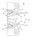
- Fig. 1 to Fig. 3 show various perspective views of an embodiment of the stabilizer according to the invention for a lower link of a three-point attachment of a tractor. With regard to structural details, in particular, the exploded view according to Fig. 4 directed.
- the stabilizer 10 comprises a first stabilizer member 12 and a second stabilizer member 14 mounted resiliently relative to the first stabilizer member 12.
- the first stabilizer member 12 is a substantially cylindrical stabilizer housing 16 within which the spring piston 18 trained second stabilizer member 14 guided longitudinally movable and by means of a spring ring 20 which engages in a circumferentially formed on the spring piston 18 groove 22, is secured.
- first stabilizer member 12 as a substantially cylindrical stabilizer housing 16 is merely exemplary in nature. Rather, a variety of other housing forms is conceivable.
- the suspension 24 urges the spring piston 18 in a predetermined rest position and causes a self-centering of a connectable to the stabilizer 10 lower link.
- the suspension 24 consists of two coil springs 26 which are mounted on opposite inner sides of the stabilizer housing 16 in associated housing recesses 28 and are positively and frictionally engaged by a recess 30 provided on the first stabilizer member 12 circumferentially.
- the housing recesses 28 may differ from the illustration in Fig. 1 to Fig. 4 be closed to the outside.
- a blocking means 32 connected to the first stabilizer member 12 is provided.
- the blocking means 32 is designed as a blocking flap 34, wherein the blocking flap 34 is pivotably connected to the first stabilizer member 12 by means of a rotational axis 36 extending transversely to the longitudinal direction of the stabilizer 10.
- the produced as a cast or forged locking flap 34 has the shape of a first stabilizer member 12 in a in Fig. 1 respectively.
- Fig. 2 shown predetermined locking position at least partially encompassing or cantilevered half shell, wherein the half-shell terminates in two opposing hinge plates 38 in which aligned bores 40 for receiving the axis of rotation 36 and thus for the production of pivotable connection with the first stabilizer member 12 are formed.
- the blocking flap 34 has a projection 42 limiting the extent of a pivoting movement.
- the projection 42 is arranged on the blocking flap 34 in such a way that, when the blocking flap 34 is pivoted outwards, it is guided out of the predetermined blocking position in the direction of the first stabilizer member 12 and brought into abutment with the pivoting movement to limit it.
- the projection 42 is an integral part of the blocking flap 34 and comprises a nose 44 aligned in the pivoting direction of the blocking flap 34.
- the blocking flap 34 also has a one-sided stop formed by a flattening 46 provided on the front side.
- the flattening 46 can be brought into abutment in the predetermined blocking position of the blocking flap 34 with a limiting means 48 such that a compression movement of the second stabilizer member 14 with respect to the first stabilizer member 12 is prevented.
- An arranged on the blocking flap 34 pull tab 50 allows a in Fig. 3 indicated pivoting out of the blocking flap 34 from the predetermined blocking position and thus a release of a compression occurring between the two stabilizer members 12 and 14.
- the limiting means 48 is designed, for example, as a limiting collar 52 provided on the second stabilizer member 14.
- the limiting collar 52 is an integral part of the second stabilizer member 14 and surrounds the second stabilizer member 14 circumferentially in the form of a flattened in the direction of the locking flap 34 ram.
- the blocking means 34 formed by the blocking means 32 in the predetermined blocking position with the limiting means 48 cooperating one-sided stop with respect to a compression movement of the second stabilizer member 14 relative to the first stabilizer member 12 is.
- the first stabilizer member 12 comprises a ball eye 54.
- the ball eye 54 consists of a formed in an end portion of the first stabilizer member 12 Befest Trentsinate 56 and a rotatably mounted therein mounting ball 58, which allows a spatial movement of the stabilizer 10 relative to the tractor.
- the second stabilizer member 14 includes a mounting leg 60 for producing a hinge connection with a lower link of a three-point implement mounting, wherein the mounting leg 60 has an attachable fork 62 attachable to the lower link.
- the second stabilizer member 14 is rotatably supported relative to the first stabilizer member 12, wherein an internal thread 64 formed within the second stabilizer member 14 engages an external thread 66 formed on the mounting leg 60 such that the stabilizer 10 is rotated by rotation of the second stabilizer member 14 relative to the first stabilizer member 12 is adjustable with respect to its overall length.
- the limiting means 48 on a handle 68 For manual rotational actuation of the second stabilizer member 14, the limiting means 48 on a handle 68.
- the handle 68 is rotatably connected to the second stabilizer member 14.
- the diameter of the handle 68 is sized so that a one-hand operation is possible.
- the handle 68 is formed by a tapering in the direction of the mounting leg 60 extension of the Begrenzungskragens 52.
- the extension has a conical shape.
- the limiting collar 52 and the handle 68 are integral with the second stabilizer member 14.
- the second stabilizer member 14, as well as the first stabilizer member 12, is a cast or forged part made of a suitable steel alloy.
- the blocking flap 34 is tapered in the direction of the limiting collar 52.
- the taper 70 is formed such that in the region of the limiting collar 52, a largely smooth course of the stabilizer outer contour is created. An undesirable deposition of contaminants, which may possibly lead to an impairment of the function of the stabilizer 10, can be reduced in this way.
- a rotation of the second stabilizer member 14 relative to the first stabilizer member 12 by means of a locking means 72 can be locked.
- the locking means 72 comprises a spring clip 74, which engages or is pressed into a recess 76 provided on the circumference of the limiting means 48.
- the spring clip 74 can be pivoted against the restoring spring force by hand from the recess 76, so that rotation of the limiting means 48 is released.
- a fastening tab 78 arranged on the first stabilizer member 12 serves to hold the spring clip 74.
- the fastening tab 78 has two transverse bores 80 and 82 spaced apart in the longitudinal direction of the stabilizer 10, wherein each of the two transverse bores 80 and 82 has an open end 84 and 86, respectively Spring clip 74 receives.
- the restoring spring force is dimensioned such that on the one hand ensures a reliable locking of the rotatable limiting means 48 On the other hand, a tool-free operation of the spring clip 74 is possible.
- the spring clip 74 is made of a stainless or similarly surface-treated round wire.
- the recess 76 has the shape of a slot-shaped depression which is oriented in the direction of a spring movement occurring between the first stabilizer member 12 and the second stabilizer member 14.
- the slot-shaped depression is designed such that it completely accommodates a locking segment 90 provided on the spring clip 74. Since the spring clip 74 is able to slide along the slot-shaped depression, a spring movement occurring between the two stabilizer elements 12 and 14 is not hindered.
- a plurality of recesses 76 are arranged evenly distributed along the circumference of the limiting means 48, so that the total length of the stabilizer 10 can be adjusted and locked in stages.
- the recesses 76 are extended in the direction of the handle 68, so that they form a grip-increasing surface structure.
- the blocking flap 34 is recessed in the region of the spring clip 74 in such a manner that pivoting out of the spring clip 74 is possible even when the blocking flap 34 is in the predetermined blocking position.
- the recess 92 has the shape of a slot oriented in the longitudinal direction of the stabilizer 10.
- Fig. 5 shows a view of a three-point implement cultivation 100 on a tractor rear 102 with mounted in the region lower link 104 stabilizers according to the invention 10.
- the illustrated upper link 106 is of conventional design, so that will not be discussed in detail.
- first stabilizer member 12 of each stabilizer 10 by means of its ball eye 54 with a on a Body part of the tractor trained first attachment point 108 and the second stabilizer member 14 by means of its mounting fork 62 with a formed on the lower link 104 second attachment point 110 articulated.
- the articulated connection produced by means of the attachment fork 62 with the lower link 104 is articulated vertically relative to the tractor-side articulated connection such that the stabilizer 10 can follow both horizontal and vertical deflections of the lower link 104.
- each of the two stabilizers 10 is connected via its respective pull tab 50 by means of a spring-loaded pull chain 112 to the tractor so that the locking flap 34 is pivoted when lifting the lower link 104 in the predetermined blocking position and a between the two stabilizer members 12 and 14 occurring compression movement is prevented.
- This is particularly advantageous in carrying out a road trip with mounted on three-point implement attachment 100 working equipment, as in this case, an undesirable swinging back and forth of the implement can be avoided.
Landscapes
- Life Sciences & Earth Sciences (AREA)
- Zoology (AREA)
- Engineering & Computer Science (AREA)
- Mechanical Engineering (AREA)
- Soil Sciences (AREA)
- Environmental Sciences (AREA)
- Soil Working Implements (AREA)
- Agricultural Machines (AREA)
- Lifting Devices For Agricultural Implements (AREA)
Claims (17)
- Stabilisateur pour une barre inférieure d'un dispositif d'attelage à trois points d'un tracteur, comprenant un premier organe stabilisateur (12) et un deuxième organe stabilisateur (14) monté sur ressort par rapport au premier organe stabilisateur (12), un moyen de blocage (32) connecté au premier organe stabilisateur (12) étant prévu, lequel, pour limiter une course de ressort du premier organe stabilisateur (12) par rapport au deuxième organe stabilisateur (14), peut être amené dans une position de blocage prédéfinie, le moyen de blocage (32) connecté au premier organe stabilisateur (12) et réalisé sous forme de clapet de blocage (34) formant, dans la position de blocage prédéfinie, une butée d'un côté coopérant avec un moyen de limitation (48) par rapport à un mouvement de compression du ressort du deuxième organe stabilisateur (14) par rapport au premier organe stabilisateur (12), caractérisé en ce que la butée est formée par un méplat (46) prévu du côté frontal sur le clapet de blocage (34).
- Stabilisateur selon la revendication 1, caractérisé en ce que le clapet de blocage (34) est connecté au moyen d'un axe pivotant (36) s'étendant transversalement à la direction longitudinale du stabilisateur (10) de manière pivotante au premier organe stabilisateur (12).
- Stabilisateur selon la revendication 1 ou 2, caractérisé en ce que le clapet de blocage (34) entoure au moins en partie le premier organe stabilisateur (12) dans la position de blocage prédéfinie.
- Stabilisateur selon l'une quelconque des revendications 1 à 3, caractérisé en ce que le clapet de blocage (34) présente une saillie (42) limitant l'ampleur d'un mouvement de pivotement.
- Stabilisateur selon l'une quelconque des revendications 1 à 4, caractérisé en ce que le premier organe stabilisateur (12) comprend un oeillet sphérique (54) pour créer une liaison articulée du côté du tracteur.
- Stabilisateur selon l'une quelconque des revendications 1 à 5, caractérisé en ce que le deuxième organe stabilisateur (14) comprend une branche de fixation (60) pour créer une liaison articulée avec une barre inférieure (104) d'un dispositif d'attelage à trois points (100).
- Stabilisateur selon la revendication 6, caractérisé en ce que le deuxième organe stabilisateur (14) est monté à rotation par rapport au premier organe stabilisateur (12), un filetage interne (64) réalisé à l'intérieur du deuxième organe stabilisateur (14) s'engageant sur un filetage externe (66) réalisé sur la branche de fixation (60) de telle sorte que le stabilisateur (10) puisse être réglé en termes de sa longueur totale par rotation du deuxième organe stabilisateur (14) par rapport au premier organe stabilisateur (12).
- Stabilisateur selon la revendication 7, caractérisé en ce que le moyen de limitation (48) est réalisé sous forme de collet de limitation (52) prévu sur le deuxième organe stabilisateur (14).
- Stabilisateur selon la revendication 8, caractérisé en ce que le moyen de limitation (48) présente une pièce de préhension (68) pour la rotation manuelle du deuxième organe stabilisateur (14).
- Stabilisateur selon la revendication 9, caractérisé en ce que la pièce de préhension (68) est formée par une saillie du collet de limitation (52) se rétrécissant dans la direction de la branche de fixation (60).
- Stabilisateur selon la revendication 9 ou 10, caractérisé en ce que le collet de limitation (52) et la pièce de préhension (68) font partie intégrante du deuxième organe stabilisateur (14).
- Stabilisateur selon les revendications 8 à 11, caractérisé en ce que le clapet de blocage (34) est rétréci dans la direction du collet de limitation (52).
- Stabilisateur selon l'une quelconque des revendications 1 à 12, caractérisé en ce qu'un réglage accidentel de la longueur totale du stabilisateur (10) peut être bloqué par le biais d'un moyen de verrouillage (72).
- Stabilisateur selon la revendication 13, caractérisé en ce que le moyen de verrouillage (72) comprend un étrier de ressort (74) qui vient en prise dans un évidement (76) prévu sur la périphérie du moyen de limitation (48).
- Stabilisateur selon la revendication 14, caractérisé en ce que l'évidement (76) présente la forme d'un renfoncement en forme de fente, qui est orienté dans la direction d'un mouvement du ressort se produisant entre le premier organe stabilisateur (12) et le deuxième organe stabilisateur (14).
- Stabilisateur selon la revendication 14 ou 15, caractérisé en ce qu'une pluralité d'évidements (76) est disposée de manière répartie uniformément le long de la périphérie du moyen de limitation (48).
- Stabilisateur selon les revendications 14 à 16, caractérisé en ce que le clapet de blocage (34) est évidé dans la région de l'étrier de ressort (74) de telle sorte qu'une sortie par pivotement de l'étrier de ressort (74) soit possible lorsque le clapet de blocage (34) se trouve dans la position de blocage prédéfinie.
Priority Applications (2)
| Application Number | Priority Date | Filing Date | Title |
|---|---|---|---|
| PL12156907T PL2457427T3 (pl) | 2009-03-26 | 2010-03-05 | Stabilizator dla dolnego sprzęgu trójpunktowego układu zawieszenia narzędzi ciągnika rolniczego |
| EP12156907.3A EP2457427B1 (fr) | 2009-03-26 | 2010-03-05 | Stabilisateur pour les avant-bras d'un attelage tracteur à trois points |
Applications Claiming Priority (1)
| Application Number | Priority Date | Filing Date | Title |
|---|---|---|---|
| DE102009001907A DE102009001907A1 (de) | 2009-03-26 | 2009-03-26 | Stabilisator für einen Unterlenker eines Dreipunktgeräteanbaus eines Traktors |
Related Child Applications (2)
| Application Number | Title | Priority Date | Filing Date |
|---|---|---|---|
| EP12156907.3A Division EP2457427B1 (fr) | 2009-03-26 | 2010-03-05 | Stabilisateur pour les avant-bras d'un attelage tracteur à trois points |
| EP12156907.3 Division-Into | 2012-02-24 |
Publications (3)
| Publication Number | Publication Date |
|---|---|
| EP2232973A2 EP2232973A2 (fr) | 2010-09-29 |
| EP2232973A3 EP2232973A3 (fr) | 2011-05-18 |
| EP2232973B1 true EP2232973B1 (fr) | 2013-02-20 |
Family
ID=42341330
Family Applications (2)
| Application Number | Title | Priority Date | Filing Date |
|---|---|---|---|
| EP10155642A Active EP2232973B1 (fr) | 2009-03-26 | 2010-03-05 | Stabilisateur pour une barre inférieure d'un dispositif d'attelage à trois points d'un tracteur |
| EP12156907.3A Active EP2457427B1 (fr) | 2009-03-26 | 2010-03-05 | Stabilisateur pour les avant-bras d'un attelage tracteur à trois points |
Family Applications After (1)
| Application Number | Title | Priority Date | Filing Date |
|---|---|---|---|
| EP12156907.3A Active EP2457427B1 (fr) | 2009-03-26 | 2010-03-05 | Stabilisateur pour les avant-bras d'un attelage tracteur à trois points |
Country Status (3)
| Country | Link |
|---|---|
| EP (2) | EP2232973B1 (fr) |
| DE (2) | DE102009001907A1 (fr) |
| PL (1) | PL2457427T3 (fr) |
Families Citing this family (5)
| Publication number | Priority date | Publication date | Assignee | Title |
|---|---|---|---|---|
| DE202011002815U1 (de) * | 2010-12-21 | 2012-01-24 | Hans Sauermann | Stabilisator für einen Unter- und/oder Oberlenker eines Ackerschleppers |
| DE102011081274A1 (de) * | 2011-08-19 | 2013-02-21 | Deere & Company | Stabilisator für einen Unterlenker eines Dreipunktgeräteanbaus eines Traktors |
| DE102011081272A1 (de) | 2011-08-19 | 2013-02-21 | Deere & Company | Stabilisator für einen Unterlenker eines Dreipunktgeräteanbaus eines Traktors |
| DE102014205281A1 (de) | 2014-03-21 | 2015-09-24 | Deere & Company | Stabilisator für einen Unterlenker eines Dreipunktgeräteanbaus eines Traktors |
| DE202014003944U1 (de) * | 2014-05-13 | 2015-08-17 | Jrs Gmbh & Co. Kg | Vorrichtung mit einer Arretiervorrichtung |
Family Cites Families (4)
| Publication number | Priority date | Publication date | Assignee | Title |
|---|---|---|---|---|
| DE8810247U1 (de) * | 1988-08-12 | 1988-09-29 | Georg Schmitt Inh. Heinz Schmitt Kraftfahrzeuge-Landtechnik, 8704 Uffenheim | Vorrichtung zur Seitenstabilisierung einer Dreipunkt-Kupplung |
| DE4310027C1 (de) * | 1993-03-27 | 1994-07-21 | Walterscheid Gmbh Gkn | Seitenstrebe für einen Unterlenker eines Traktors |
| FI970496A0 (fi) * | 1997-02-06 | 1997-02-06 | Avant Tecno Oy | Sidobegraensare |
| ES2218513T3 (es) * | 2002-03-04 | 2004-11-16 | Cbm S.P.A. | Estabilizador lateral para los brazos inferiores de enganches de tres puntos. |
-
2009
- 2009-03-26 DE DE102009001907A patent/DE102009001907A1/de not_active Withdrawn
-
2010
- 2010-03-05 PL PL12156907T patent/PL2457427T3/pl unknown
- 2010-03-05 EP EP10155642A patent/EP2232973B1/fr active Active
- 2010-03-05 EP EP12156907.3A patent/EP2457427B1/fr active Active
- 2010-03-05 DE DE202010017641U patent/DE202010017641U1/de not_active Expired - Lifetime
Also Published As
| Publication number | Publication date |
|---|---|
| EP2232973A2 (fr) | 2010-09-29 |
| EP2457427B1 (fr) | 2014-03-26 |
| EP2457427A3 (fr) | 2012-10-31 |
| PL2457427T3 (pl) | 2014-08-29 |
| EP2457427A2 (fr) | 2012-05-30 |
| DE202010017641U1 (de) | 2012-03-22 |
| EP2232973A3 (fr) | 2011-05-18 |
| DE102009001907A1 (de) | 2010-09-30 |
Similar Documents
| Publication | Publication Date | Title |
|---|---|---|
| EP2744320B1 (fr) | Stabilisateur pour barre d'attelage inférieure d'un attelage trois points de tracteur | |
| EP2656708B1 (fr) | Herse à pointes | |
| EP2926638B1 (fr) | Stabilisateur pour une barre inférieure d'une prise de force à trois points d'un tracteur | |
| EP2594473B1 (fr) | Dispositif à dérailleur pour un agencement de vitesses de vélo, notamment dispositif à dérailleur arrière | |
| AT404779B (de) | Seitenstrebe für den unterlenker eines traktors | |
| AT398149B (de) | Seitenstrebe für die unterlenker einer dreipunktanbauvorrichtung | |
| EP2232973B1 (fr) | Stabilisateur pour une barre inférieure d'un dispositif d'attelage à trois points d'un tracteur | |
| AT510436B1 (de) | Karabinerhaken | |
| EP1880590B1 (fr) | Dispositif d'une machine agricole | |
| EP3228165B1 (fr) | Stabilisateur pour une barre inférieure d'une prise de force à trois points d'un tracteur | |
| EP2556736B1 (fr) | Colonne de levage modifiable en longueur | |
| EP3708869B1 (fr) | Crochet de raccourcissement pourvu de raccord à la coupole | |
| WO2011069179A1 (fr) | Charnière de meuble | |
| DE60200422T2 (de) | Unterlenkerstabilisator für Dreipunktaufhängung | |
| DE202011103255U1 (de) | Karabinerhaken | |
| DE102008007299A1 (de) | Unterlenkerzusammenbau für eine Anbaueinrichtung eines Traktors | |
| EP2992747B1 (fr) | Dispositif de fixation pour une barre inférieure d'un attelage trois point d'un tracteur agricole | |
| EP2946646B1 (fr) | Dispositif doté d'un dispositif d'arrêt | |
| EP3395743A1 (fr) | Dispositif de raccourcissement pour une chaîne à maillons | |
| DE9110358U1 (de) | Karabinerhaken | |
| EP2770154B1 (fr) | Élément de regroupement pour le regroupement d'au moins deux cordons d'actionnement pour une installation d'ombrage | |
| EP4014704B1 (fr) | Stabilisateur | |
| EP4445706A1 (fr) | Entretoise latérale pour stabiliser un bras inférieur d'un attelage trois points d'un tracteur | |
| DE2456971C2 (de) | Kupplungshaken, insbesondere für ein Dreipunktgestänge eines Schleppers | |
| DE2648070C2 (de) | Längenveränderbarer, eine Schraubenfeder aufweisender elastischer Distanzhalter für die Unterlenker von Dreipunk tanhängevorrichtungen |
Legal Events
| Date | Code | Title | Description |
|---|---|---|---|
| PUAI | Public reference made under article 153(3) epc to a published international application that has entered the european phase |
Free format text: ORIGINAL CODE: 0009012 |
|
| AK | Designated contracting states |
Kind code of ref document: A2 Designated state(s): AT BE BG CH CY CZ DE DK EE ES FI FR GB GR HR HU IE IS IT LI LT LU LV MC MK MT NL NO PL PT RO SE SI SK SM TR |
|
| AX | Request for extension of the european patent |
Extension state: AL BA ME RS |
|
| PUAL | Search report despatched |
Free format text: ORIGINAL CODE: 0009013 |
|
| AK | Designated contracting states |
Kind code of ref document: A3 Designated state(s): AT BE BG CH CY CZ DE DK EE ES FI FR GB GR HR HU IE IS IT LI LT LU LV MC MK MT NL NO PL PT RO SE SI SK SM TR |
|
| AX | Request for extension of the european patent |
Extension state: AL BA ME RS |
|
| 17P | Request for examination filed |
Effective date: 20111118 |
|
| GRAP | Despatch of communication of intention to grant a patent |
Free format text: ORIGINAL CODE: EPIDOSNIGR1 |
|
| GRAS | Grant fee paid |
Free format text: ORIGINAL CODE: EPIDOSNIGR3 |
|
| GRAA | (expected) grant |
Free format text: ORIGINAL CODE: 0009210 |
|
| AK | Designated contracting states |
Kind code of ref document: B1 Designated state(s): AT BE BG CH CY CZ DE DK EE ES FI FR GB GR HR HU IE IS IT LI LT LU LV MC MK MT NL NO PL PT RO SE SI SK SM TR |
|
| REG | Reference to a national code |
Ref country code: GB Ref legal event code: FG4D Free format text: NOT ENGLISH |
|
| REG | Reference to a national code |
Ref country code: CH Ref legal event code: EP |
|
| REG | Reference to a national code |
Ref country code: AT Ref legal event code: REF Ref document number: 597091 Country of ref document: AT Kind code of ref document: T Effective date: 20130315 |
|
| REG | Reference to a national code |
Ref country code: IE Ref legal event code: FG4D Free format text: LANGUAGE OF EP DOCUMENT: GERMAN |
|
| REG | Reference to a national code |
Ref country code: DE Ref legal event code: R096 Ref document number: 502010002345 Country of ref document: DE Effective date: 20130418 |
|
| REG | Reference to a national code |
Ref country code: NL Ref legal event code: VDEP Effective date: 20130220 |
|
| REG | Reference to a national code |
Ref country code: LT Ref legal event code: MG4D |
|
| PG25 | Lapsed in a contracting state [announced via postgrant information from national office to epo] |
Ref country code: ES Free format text: LAPSE BECAUSE OF FAILURE TO SUBMIT A TRANSLATION OF THE DESCRIPTION OR TO PAY THE FEE WITHIN THE PRESCRIBED TIME-LIMIT Effective date: 20130531 Ref country code: IS Free format text: LAPSE BECAUSE OF FAILURE TO SUBMIT A TRANSLATION OF THE DESCRIPTION OR TO PAY THE FEE WITHIN THE PRESCRIBED TIME-LIMIT Effective date: 20130620 Ref country code: LT Free format text: LAPSE BECAUSE OF FAILURE TO SUBMIT A TRANSLATION OF THE DESCRIPTION OR TO PAY THE FEE WITHIN THE PRESCRIBED TIME-LIMIT Effective date: 20130220 Ref country code: SE Free format text: LAPSE BECAUSE OF FAILURE TO SUBMIT A TRANSLATION OF THE DESCRIPTION OR TO PAY THE FEE WITHIN THE PRESCRIBED TIME-LIMIT Effective date: 20130220 Ref country code: BG Free format text: LAPSE BECAUSE OF FAILURE TO SUBMIT A TRANSLATION OF THE DESCRIPTION OR TO PAY THE FEE WITHIN THE PRESCRIBED TIME-LIMIT Effective date: 20130520 Ref country code: NO Free format text: LAPSE BECAUSE OF FAILURE TO SUBMIT A TRANSLATION OF THE DESCRIPTION OR TO PAY THE FEE WITHIN THE PRESCRIBED TIME-LIMIT Effective date: 20130520 |
|
| PG25 | Lapsed in a contracting state [announced via postgrant information from national office to epo] |
Ref country code: LV Free format text: LAPSE BECAUSE OF FAILURE TO SUBMIT A TRANSLATION OF THE DESCRIPTION OR TO PAY THE FEE WITHIN THE PRESCRIBED TIME-LIMIT Effective date: 20130220 Ref country code: SI Free format text: LAPSE BECAUSE OF FAILURE TO SUBMIT A TRANSLATION OF THE DESCRIPTION OR TO PAY THE FEE WITHIN THE PRESCRIBED TIME-LIMIT Effective date: 20130220 Ref country code: PL Free format text: LAPSE BECAUSE OF FAILURE TO SUBMIT A TRANSLATION OF THE DESCRIPTION OR TO PAY THE FEE WITHIN THE PRESCRIBED TIME-LIMIT Effective date: 20130220 Ref country code: PT Free format text: LAPSE BECAUSE OF FAILURE TO SUBMIT A TRANSLATION OF THE DESCRIPTION OR TO PAY THE FEE WITHIN THE PRESCRIBED TIME-LIMIT Effective date: 20130620 Ref country code: GR Free format text: LAPSE BECAUSE OF FAILURE TO SUBMIT A TRANSLATION OF THE DESCRIPTION OR TO PAY THE FEE WITHIN THE PRESCRIBED TIME-LIMIT Effective date: 20130521 |
|
| BERE | Be: lapsed |
Owner name: DEERE & CY Effective date: 20130331 |
|
| PG25 | Lapsed in a contracting state [announced via postgrant information from national office to epo] |
Ref country code: HR Free format text: LAPSE BECAUSE OF FAILURE TO SUBMIT A TRANSLATION OF THE DESCRIPTION OR TO PAY THE FEE WITHIN THE PRESCRIBED TIME-LIMIT Effective date: 20130220 |
|
| PG25 | Lapsed in a contracting state [announced via postgrant information from national office to epo] |
Ref country code: NL Free format text: LAPSE BECAUSE OF FAILURE TO SUBMIT A TRANSLATION OF THE DESCRIPTION OR TO PAY THE FEE WITHIN THE PRESCRIBED TIME-LIMIT Effective date: 20130220 Ref country code: DK Free format text: LAPSE BECAUSE OF FAILURE TO SUBMIT A TRANSLATION OF THE DESCRIPTION OR TO PAY THE FEE WITHIN THE PRESCRIBED TIME-LIMIT Effective date: 20130220 Ref country code: MC Free format text: LAPSE BECAUSE OF NON-PAYMENT OF DUE FEES Effective date: 20130331 Ref country code: SK Free format text: LAPSE BECAUSE OF FAILURE TO SUBMIT A TRANSLATION OF THE DESCRIPTION OR TO PAY THE FEE WITHIN THE PRESCRIBED TIME-LIMIT Effective date: 20130220 Ref country code: RO Free format text: LAPSE BECAUSE OF FAILURE TO SUBMIT A TRANSLATION OF THE DESCRIPTION OR TO PAY THE FEE WITHIN THE PRESCRIBED TIME-LIMIT Effective date: 20130220 Ref country code: EE Free format text: LAPSE BECAUSE OF FAILURE TO SUBMIT A TRANSLATION OF THE DESCRIPTION OR TO PAY THE FEE WITHIN THE PRESCRIBED TIME-LIMIT Effective date: 20130220 Ref country code: CZ Free format text: LAPSE BECAUSE OF FAILURE TO SUBMIT A TRANSLATION OF THE DESCRIPTION OR TO PAY THE FEE WITHIN THE PRESCRIBED TIME-LIMIT Effective date: 20130220 |
|
| PLBE | No opposition filed within time limit |
Free format text: ORIGINAL CODE: 0009261 |
|
| STAA | Information on the status of an ep patent application or granted ep patent |
Free format text: STATUS: NO OPPOSITION FILED WITHIN TIME LIMIT |
|
| REG | Reference to a national code |
Ref country code: IE Ref legal event code: MM4A |
|
| 26N | No opposition filed |
Effective date: 20131121 |
|
| PG25 | Lapsed in a contracting state [announced via postgrant information from national office to epo] |
Ref country code: BE Free format text: LAPSE BECAUSE OF NON-PAYMENT OF DUE FEES Effective date: 20130331 Ref country code: IE Free format text: LAPSE BECAUSE OF NON-PAYMENT OF DUE FEES Effective date: 20130305 |
|
| REG | Reference to a national code |
Ref country code: DE Ref legal event code: R097 Ref document number: 502010002345 Country of ref document: DE Effective date: 20131121 |
|
| PGFP | Annual fee paid to national office [announced via postgrant information from national office to epo] |
Ref country code: DE Payment date: 20140219 Year of fee payment: 5 Ref country code: FI Payment date: 20140327 Year of fee payment: 5 |
|
| PGFP | Annual fee paid to national office [announced via postgrant information from national office to epo] |
Ref country code: IT Payment date: 20140320 Year of fee payment: 5 |
|
| PG25 | Lapsed in a contracting state [announced via postgrant information from national office to epo] |
Ref country code: MT Free format text: LAPSE BECAUSE OF FAILURE TO SUBMIT A TRANSLATION OF THE DESCRIPTION OR TO PAY THE FEE WITHIN THE PRESCRIBED TIME-LIMIT Effective date: 20130220 |
|
| REG | Reference to a national code |
Ref country code: CH Ref legal event code: PL |
|
| PG25 | Lapsed in a contracting state [announced via postgrant information from national office to epo] |
Ref country code: CH Free format text: LAPSE BECAUSE OF NON-PAYMENT OF DUE FEES Effective date: 20140331 Ref country code: LI Free format text: LAPSE BECAUSE OF NON-PAYMENT OF DUE FEES Effective date: 20140331 |
|
| PG25 | Lapsed in a contracting state [announced via postgrant information from national office to epo] |
Ref country code: SM Free format text: LAPSE BECAUSE OF FAILURE TO SUBMIT A TRANSLATION OF THE DESCRIPTION OR TO PAY THE FEE WITHIN THE PRESCRIBED TIME-LIMIT Effective date: 20130220 |
|
| PG25 | Lapsed in a contracting state [announced via postgrant information from national office to epo] |
Ref country code: TR Free format text: LAPSE BECAUSE OF FAILURE TO SUBMIT A TRANSLATION OF THE DESCRIPTION OR TO PAY THE FEE WITHIN THE PRESCRIBED TIME-LIMIT Effective date: 20130220 Ref country code: CY Free format text: LAPSE BECAUSE OF FAILURE TO SUBMIT A TRANSLATION OF THE DESCRIPTION OR TO PAY THE FEE WITHIN THE PRESCRIBED TIME-LIMIT Effective date: 20130220 |
|
| PG25 | Lapsed in a contracting state [announced via postgrant information from national office to epo] |
Ref country code: MK Free format text: LAPSE BECAUSE OF FAILURE TO SUBMIT A TRANSLATION OF THE DESCRIPTION OR TO PAY THE FEE WITHIN THE PRESCRIBED TIME-LIMIT Effective date: 20130220 Ref country code: LU Free format text: LAPSE BECAUSE OF NON-PAYMENT OF DUE FEES Effective date: 20130305 Ref country code: HU Free format text: LAPSE BECAUSE OF FAILURE TO SUBMIT A TRANSLATION OF THE DESCRIPTION OR TO PAY THE FEE WITHIN THE PRESCRIBED TIME-LIMIT; INVALID AB INITIO Effective date: 20100305 |
|
| REG | Reference to a national code |
Ref country code: DE Ref legal event code: R119 Ref document number: 502010002345 Country of ref document: DE |
|
| PG25 | Lapsed in a contracting state [announced via postgrant information from national office to epo] |
Ref country code: FI Free format text: LAPSE BECAUSE OF NON-PAYMENT OF DUE FEES Effective date: 20150305 |
|
| PG25 | Lapsed in a contracting state [announced via postgrant information from national office to epo] |
Ref country code: IT Free format text: LAPSE BECAUSE OF NON-PAYMENT OF DUE FEES Effective date: 20150305 |
|
| PG25 | Lapsed in a contracting state [announced via postgrant information from national office to epo] |
Ref country code: DE Free format text: LAPSE BECAUSE OF NON-PAYMENT OF DUE FEES Effective date: 20151001 |
|
| REG | Reference to a national code |
Ref country code: FR Ref legal event code: PLFP Year of fee payment: 7 |
|
| REG | Reference to a national code |
Ref country code: AT Ref legal event code: MM01 Ref document number: 597091 Country of ref document: AT Kind code of ref document: T Effective date: 20150305 |
|
| PG25 | Lapsed in a contracting state [announced via postgrant information from national office to epo] |
Ref country code: AT Free format text: LAPSE BECAUSE OF NON-PAYMENT OF DUE FEES Effective date: 20150305 |
|
| REG | Reference to a national code |
Ref country code: FR Ref legal event code: PLFP Year of fee payment: 8 |
|
| REG | Reference to a national code |
Ref country code: FR Ref legal event code: PLFP Year of fee payment: 9 |
|
| PGFP | Annual fee paid to national office [announced via postgrant information from national office to epo] |
Ref country code: GB Payment date: 20240327 Year of fee payment: 15 |
|
| PGFP | Annual fee paid to national office [announced via postgrant information from national office to epo] |
Ref country code: FR Payment date: 20240325 Year of fee payment: 15 |