EP2232973B1 - Stabiliser for a lower link of a three-point hitch of a tractor - Google Patents
Stabiliser for a lower link of a three-point hitch of a tractor Download PDFInfo
- Publication number
- EP2232973B1 EP2232973B1 EP10155642A EP10155642A EP2232973B1 EP 2232973 B1 EP2232973 B1 EP 2232973B1 EP 10155642 A EP10155642 A EP 10155642A EP 10155642 A EP10155642 A EP 10155642A EP 2232973 B1 EP2232973 B1 EP 2232973B1
- Authority
- EP
- European Patent Office
- Prior art keywords
- stabilizer
- blocking
- stabilizer element
- limiting
- flap
- Prior art date
- Legal status (The legal status is an assumption and is not a legal conclusion. Google has not performed a legal analysis and makes no representation as to the accuracy of the status listed.)
- Active
Links
- 239000003381 stabilizer Substances 0.000 title claims description 184
- 230000000903 blocking effect Effects 0.000 claims description 65
- 230000006835 compression Effects 0.000 description 7
- 238000007906 compression Methods 0.000 description 7
- 239000000725 suspension Substances 0.000 description 3
- 229910000851 Alloy steel Inorganic materials 0.000 description 2
- 230000004888 barrier function Effects 0.000 description 2
- 238000010276 construction Methods 0.000 description 2
- 239000000356 contaminant Substances 0.000 description 2
- 238000011109 contamination Methods 0.000 description 2
- 230000006735 deficit Effects 0.000 description 2
- 230000008021 deposition Effects 0.000 description 2
- 230000001419 dependent effect Effects 0.000 description 1
- 238000004519 manufacturing process Methods 0.000 description 1
Images


Classifications
-
- A—HUMAN NECESSITIES
- A01—AGRICULTURE; FORESTRY; ANIMAL HUSBANDRY; HUNTING; TRAPPING; FISHING
- A01B—SOIL WORKING IN AGRICULTURE OR FORESTRY; PARTS, DETAILS, OR ACCESSORIES OF AGRICULTURAL MACHINES OR IMPLEMENTS, IN GENERAL
- A01B59/00—Devices specially adapted for connection between animals or tractors and agricultural machines or implements
- A01B59/04—Devices specially adapted for connection between animals or tractors and agricultural machines or implements for machines pulled or pushed by a tractor
- A01B59/041—Devices specially adapted for connection between animals or tractors and agricultural machines or implements for machines pulled or pushed by a tractor preventing or limiting side-play of implements
Definitions
- the invention relates to a stabilizer for a lower link of a three-point attachment of a tractor, comprising a first stabilizer member and a second stabilizer member resiliently mounted with respect to the first stabilizer member, wherein a locking means connected to the first stabilizer member is provided for limiting a spring movement of the first stabilizer member relative to the second Stabilizer member can be brought into a predetermined blocking position.
- Such a stabilizer for a lower link of a three-point attachment to a tractor is from the DE 602 00 422 T2 and US 5,462,303 known.
- the articulated between the tractor and lower link stabilizer comprises a first and a second stabilizer member, wherein the two stabilizer members are connected together so that they can move against each other resiliently.
- a blocking means pivotably hinged to the first stabilizer member serves to lock the two stabilizer members against each other, for which purpose a recess provided in the blocking means can be engaged with a projection formed on the second stabilizer member.
- the stabilizer for a lower link of a three-point attachment of a tractor comprises a first stabilizer member and a second stabilizer member resiliently mounted relative to the first stabilizer member, wherein a locking means connected to the first stabilizer member is provided for limiting a spring movement of the first stabilizer member relative to the second stabilizer member in a predetermined Lock position can be brought.
- the locking means connected to the first stabilizer member in the predetermined locking position forms a one-sided stop cooperating with a limiting means with respect to a compression movement of the second stabilizer member relative to the first stabilizer member.
- the first stabilizer member is, in particular, a substantially cylindrical stabilizer housing, within which the second stabilizer member designed as a spring piston is longitudinally movably guided.
- a arranged between an inner side of the stabilizer housing and the spring piston suspension in the form of one or more coil springs urges the spring piston in a predetermined rest position and causes a self-centering of the lower link.
- the blocking means is designed as a blocking flap, wherein the blocking flap is connected by means of a transverse to the longitudinal direction of the stabilizer axis of rotation pivotally connected to the first stabilizer member.
- the blocking flap can be connected to the tractor via a pull tab by means of a pull rope or a pull chain in such a way that it is automatically pivoted into the predetermined blocking position when the lower link is lifted.
- the blocking flap can at least partially enclose the first stabilizer member in the predetermined blocking position, so that additional protection against soiling is provided.
- the locking flap manufactured as a cast or forged part has in particular the shape of a half shell which at least partially surrounds or overlaps the first stabilizer member, the half shell terminating in two opposite hinge straps by means of which a pivotable connection with the first stabilizer member can be produced.
- the one-sided stop is formed, in particular, by a flattening provided on the blocking flap on the front side.
- the flattening can be brought in the predetermined blocking position of the blocking flap with the limiting means to the plant in such a way that a compression movement of the second stabilizer member relative to the first stabilizer member is prevented.
- the blocking flap has a projection which limits an extent of a pivoting movement.
- the projection is preferably arranged on the blocking flap in such a way that, when the blocking flap is pivoted outwards, it is guided out of the predetermined blocking position in the direction of the first stabilizer member and brought into abutment therewith for limiting the pivoting movement.
- the projection is preferably an integral part of the blocking flap.
- the first stabilizer member may comprise a ball eye.
- the ball eye consists of a formed in an end region of the first stabilizer member mounting lug and a rotatably mounted therein mounting ball, which allows a spatial movement of the stabilizer relative to the tractor.
- the second stabilizer member may comprise a mounting leg for producing a hinge connection with a lower link of a three-point attachment.
- the attachment leg has an attachment fork which can be attached to the lower link, wherein the articulated connection which can be produced by means of the attachment fork with the lower link is articulated perpendicular to the tractor-side articulated connection such that the stabilizer can follow both horizontal and vertical deflections of the lower link.
- the limiting means is designed in particular as provided on the second stabilizer member limiting collar.
- the limiting collar can be an integral part of the second stabilizer member and project circumferentially in the form of a flattened in the direction of the locking flap ram.
- the second stabilizer member is rotatably mounted relative to the first stabilizer member, wherein an internal thread formed within the second stabilizer member engages an external thread formed on the mounting leg such that the stabilizer is adjustable relative to the first stabilizer member with respect to its overall length by rotation of the second stabilizer member.
- the position of the lower link can be adapted to the dimensions of different attachment interfaces.
- the limiting means may comprise a handle or be formed as such.
- the handle is rotatably connected to the second stabilizer member.
- the handle can be provided with a suitable surface structure.
- the diameter of the handle is preferably dimensioned such that a one-hand operation is possible.
- the handle is formed in particular by a tapering in the direction of the mounting leg extension of the Begrenzungskkragens.
- the extension can have an easily manufactured conical shape.
- the limiting collar and the handle may be integral with the second stabilizer member.
- the second stabilizer member - as well as the first stabilizer member - may be a cast or forged part made of a suitable steel alloy.
- the blocking flap is tapered in the direction of the limiting collar.
- the taper is shaped such that in the predetermined blocking position of the blocking flap in the region of the limiting collar, a largely smooth course of the stabilizer outer contour is created. An undesirable deposition of contaminants, which may possibly lead to impairment of the function of the stabilizer, can be reduced in this way.
- a rotation of the second stabilizer member relative to the first stabilizer member by means of a locking means can be locked.
- the locking means may comprise a spring clip, which engages in a recess provided on the periphery of the limiting means or pressed.
- the spring clip can be pivoted against the restoring spring force by hand from the recess, so that rotation of the limiting means is released.
- this comprises at its free end a loop-shaped widened grip area.
- the restoring spring force is dimensioned such that on the one hand a reliable locking of the rotatable limiting means is ensured, on the other hand, a tool-free operation of the spring clip is possible.
- the spring clip is made for example of a stainless or similarly surface-treated round wire.
- the recess has, in particular, the shape of a slot-shaped recess which is oriented in the direction of a spring movement occurring between the first stabilizer member and the second stabilizer member.
- the slot-shaped depression is designed such that it completely accommodates a locking segment provided on the spring clip. Since the spring clip is able to slide along the slot-shaped depression, a spring movement occurring between the two stabilizer elements is not hindered.
- a plurality of recesses is arranged distributed uniformly along the circumference of the limiting means, so that the total length of the stabilizer can be adjusted in stages and locked.
- the number and thus the spacing of the recesses can be dimensioned such that they form a grooved friction surface, which allows a quasi-continuous adjustment and locking of the limiting means.
- the locking flap is recessed in the region of the spring clip such that a pivoting out of the spring clip is also possible in the predetermined blocking position befindaji locking flap.
- the recess has, for example, the shape of a slit oriented in the longitudinal direction of the stabilizer.
- the spring clip is provided on a side facing away from the barrier flap of the stabilizer. A recess in the area of the blocking flap is unnecessary in this case.
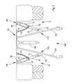
- Fig. 1 to Fig. 3 show various perspective views of an embodiment of the stabilizer according to the invention for a lower link of a three-point attachment of a tractor. With regard to structural details, in particular, the exploded view according to Fig. 4 directed.
- the stabilizer 10 comprises a first stabilizer member 12 and a second stabilizer member 14 mounted resiliently relative to the first stabilizer member 12.
- the first stabilizer member 12 is a substantially cylindrical stabilizer housing 16 within which the spring piston 18 trained second stabilizer member 14 guided longitudinally movable and by means of a spring ring 20 which engages in a circumferentially formed on the spring piston 18 groove 22, is secured.
- first stabilizer member 12 as a substantially cylindrical stabilizer housing 16 is merely exemplary in nature. Rather, a variety of other housing forms is conceivable.
- the suspension 24 urges the spring piston 18 in a predetermined rest position and causes a self-centering of a connectable to the stabilizer 10 lower link.
- the suspension 24 consists of two coil springs 26 which are mounted on opposite inner sides of the stabilizer housing 16 in associated housing recesses 28 and are positively and frictionally engaged by a recess 30 provided on the first stabilizer member 12 circumferentially.
- the housing recesses 28 may differ from the illustration in Fig. 1 to Fig. 4 be closed to the outside.
- a blocking means 32 connected to the first stabilizer member 12 is provided.
- the blocking means 32 is designed as a blocking flap 34, wherein the blocking flap 34 is pivotably connected to the first stabilizer member 12 by means of a rotational axis 36 extending transversely to the longitudinal direction of the stabilizer 10.
- the produced as a cast or forged locking flap 34 has the shape of a first stabilizer member 12 in a in Fig. 1 respectively.
- Fig. 2 shown predetermined locking position at least partially encompassing or cantilevered half shell, wherein the half-shell terminates in two opposing hinge plates 38 in which aligned bores 40 for receiving the axis of rotation 36 and thus for the production of pivotable connection with the first stabilizer member 12 are formed.
- the blocking flap 34 has a projection 42 limiting the extent of a pivoting movement.
- the projection 42 is arranged on the blocking flap 34 in such a way that, when the blocking flap 34 is pivoted outwards, it is guided out of the predetermined blocking position in the direction of the first stabilizer member 12 and brought into abutment with the pivoting movement to limit it.
- the projection 42 is an integral part of the blocking flap 34 and comprises a nose 44 aligned in the pivoting direction of the blocking flap 34.
- the blocking flap 34 also has a one-sided stop formed by a flattening 46 provided on the front side.
- the flattening 46 can be brought into abutment in the predetermined blocking position of the blocking flap 34 with a limiting means 48 such that a compression movement of the second stabilizer member 14 with respect to the first stabilizer member 12 is prevented.
- An arranged on the blocking flap 34 pull tab 50 allows a in Fig. 3 indicated pivoting out of the blocking flap 34 from the predetermined blocking position and thus a release of a compression occurring between the two stabilizer members 12 and 14.
- the limiting means 48 is designed, for example, as a limiting collar 52 provided on the second stabilizer member 14.
- the limiting collar 52 is an integral part of the second stabilizer member 14 and surrounds the second stabilizer member 14 circumferentially in the form of a flattened in the direction of the locking flap 34 ram.
- the blocking means 34 formed by the blocking means 32 in the predetermined blocking position with the limiting means 48 cooperating one-sided stop with respect to a compression movement of the second stabilizer member 14 relative to the first stabilizer member 12 is.
- the first stabilizer member 12 comprises a ball eye 54.
- the ball eye 54 consists of a formed in an end portion of the first stabilizer member 12 Befest Trentsinate 56 and a rotatably mounted therein mounting ball 58, which allows a spatial movement of the stabilizer 10 relative to the tractor.
- the second stabilizer member 14 includes a mounting leg 60 for producing a hinge connection with a lower link of a three-point implement mounting, wherein the mounting leg 60 has an attachable fork 62 attachable to the lower link.
- the second stabilizer member 14 is rotatably supported relative to the first stabilizer member 12, wherein an internal thread 64 formed within the second stabilizer member 14 engages an external thread 66 formed on the mounting leg 60 such that the stabilizer 10 is rotated by rotation of the second stabilizer member 14 relative to the first stabilizer member 12 is adjustable with respect to its overall length.
- the limiting means 48 on a handle 68 For manual rotational actuation of the second stabilizer member 14, the limiting means 48 on a handle 68.
- the handle 68 is rotatably connected to the second stabilizer member 14.
- the diameter of the handle 68 is sized so that a one-hand operation is possible.
- the handle 68 is formed by a tapering in the direction of the mounting leg 60 extension of the Begrenzungskragens 52.
- the extension has a conical shape.
- the limiting collar 52 and the handle 68 are integral with the second stabilizer member 14.
- the second stabilizer member 14, as well as the first stabilizer member 12, is a cast or forged part made of a suitable steel alloy.
- the blocking flap 34 is tapered in the direction of the limiting collar 52.
- the taper 70 is formed such that in the region of the limiting collar 52, a largely smooth course of the stabilizer outer contour is created. An undesirable deposition of contaminants, which may possibly lead to an impairment of the function of the stabilizer 10, can be reduced in this way.
- a rotation of the second stabilizer member 14 relative to the first stabilizer member 12 by means of a locking means 72 can be locked.
- the locking means 72 comprises a spring clip 74, which engages or is pressed into a recess 76 provided on the circumference of the limiting means 48.
- the spring clip 74 can be pivoted against the restoring spring force by hand from the recess 76, so that rotation of the limiting means 48 is released.
- a fastening tab 78 arranged on the first stabilizer member 12 serves to hold the spring clip 74.
- the fastening tab 78 has two transverse bores 80 and 82 spaced apart in the longitudinal direction of the stabilizer 10, wherein each of the two transverse bores 80 and 82 has an open end 84 and 86, respectively Spring clip 74 receives.
- the restoring spring force is dimensioned such that on the one hand ensures a reliable locking of the rotatable limiting means 48 On the other hand, a tool-free operation of the spring clip 74 is possible.
- the spring clip 74 is made of a stainless or similarly surface-treated round wire.
- the recess 76 has the shape of a slot-shaped depression which is oriented in the direction of a spring movement occurring between the first stabilizer member 12 and the second stabilizer member 14.
- the slot-shaped depression is designed such that it completely accommodates a locking segment 90 provided on the spring clip 74. Since the spring clip 74 is able to slide along the slot-shaped depression, a spring movement occurring between the two stabilizer elements 12 and 14 is not hindered.
- a plurality of recesses 76 are arranged evenly distributed along the circumference of the limiting means 48, so that the total length of the stabilizer 10 can be adjusted and locked in stages.
- the recesses 76 are extended in the direction of the handle 68, so that they form a grip-increasing surface structure.
- the blocking flap 34 is recessed in the region of the spring clip 74 in such a manner that pivoting out of the spring clip 74 is possible even when the blocking flap 34 is in the predetermined blocking position.
- the recess 92 has the shape of a slot oriented in the longitudinal direction of the stabilizer 10.
- Fig. 5 shows a view of a three-point implement cultivation 100 on a tractor rear 102 with mounted in the region lower link 104 stabilizers according to the invention 10.
- the illustrated upper link 106 is of conventional design, so that will not be discussed in detail.
- first stabilizer member 12 of each stabilizer 10 by means of its ball eye 54 with a on a Body part of the tractor trained first attachment point 108 and the second stabilizer member 14 by means of its mounting fork 62 with a formed on the lower link 104 second attachment point 110 articulated.
- the articulated connection produced by means of the attachment fork 62 with the lower link 104 is articulated vertically relative to the tractor-side articulated connection such that the stabilizer 10 can follow both horizontal and vertical deflections of the lower link 104.
- each of the two stabilizers 10 is connected via its respective pull tab 50 by means of a spring-loaded pull chain 112 to the tractor so that the locking flap 34 is pivoted when lifting the lower link 104 in the predetermined blocking position and a between the two stabilizer members 12 and 14 occurring compression movement is prevented.
- This is particularly advantageous in carrying out a road trip with mounted on three-point implement attachment 100 working equipment, as in this case, an undesirable swinging back and forth of the implement can be avoided.
Description
Die Erfindung betrifft einen Stabilisator für einen Unterlenker eines Dreipunktgeräteanbaus eines Traktors, mit einem ersten Stabilisatorglied und einem gegenüber dem ersten Stabilisatorglied federnd gelagerten zweiten Stabilisatorglied, wobei ein mit dem ersten Stabilisatorglied verbundenes Sperrmittel vorgesehen ist, das zur Einschränkung einer Federbewegung des ersten Stabilisatorglieds gegenüber dem zweiten Stabilisatorglied in eine vorgegebene Sperrstellung verbringbar ist.The invention relates to a stabilizer for a lower link of a three-point attachment of a tractor, comprising a first stabilizer member and a second stabilizer member resiliently mounted with respect to the first stabilizer member, wherein a locking means connected to the first stabilizer member is provided for limiting a spring movement of the first stabilizer member relative to the second Stabilizer member can be brought into a predetermined blocking position.
Ein derartiger Stabilisator für einen Unterlenker eines Dreipunktgeräteanbaus an einem Traktor ist aus der
Es ist daher Aufgabe der vorliegenden Erfindung, einen Stabilisator mit einem gegenüber Verschmutzungen unempfindlichen Sperrmittel anzugeben.It is therefore an object of the present invention to provide a stabilizer with a pollution-insensitive barrier means.
Diese Aufgabe wird gemäß den Merkmalen des Patentanspruchs 1 gelöst.This object is achieved according to the features of patent claim 1.
Der Stabilisator für einen Unterlenker eines Dreipunktgeräteanbaus eines Traktors umfasst ein erstes Stabilisatorglied und ein gegenüber dem ersten Stabilisatorglied federnd gelagertes zweites Stabilisatorglied, wobei ein mit dem ersten Stabilisatorglied verbundenes Sperrmittel vorgesehen ist, das zur Einschränkung einer Federbewegung des ersten Stabilisatorglieds gegenüber dem zweiten Stabilisatorglied in eine vorgegebene Sperrstellung verbringbar ist. Erfindungsgemäß bildet das mit dem ersten Stabilisatorglied verbundene Sperrmittel in der vorgegebenen Sperrstellung einen mit einem Begrenzungsmittel zusammenwirkenden einseitigen Anschlag in Bezug auf eine Einfederbewegung des zweiten Stabilisatorglieds gegenüber dem ersten Stabilisatorglied.The stabilizer for a lower link of a three-point attachment of a tractor comprises a first stabilizer member and a second stabilizer member resiliently mounted relative to the first stabilizer member, wherein a locking means connected to the first stabilizer member is provided for limiting a spring movement of the first stabilizer member relative to the second stabilizer member in a predetermined Lock position can be brought. According to the invention, the locking means connected to the first stabilizer member in the predetermined locking position forms a one-sided stop cooperating with a limiting means with respect to a compression movement of the second stabilizer member relative to the first stabilizer member.
Aufgrund der Verwendung eines einseitigen Anschlags und der dadurch ermöglichten offenen Bauweise des Sperrmittels ist dieses vergleichsweise unempfindlich gegenüber Verschmutzungen. Da von dem Sperrmittel ausschließlich eine am Stabilisator auftretende Einfederbewegung blockiert wird, nicht jedoch eine in entgegengesetzter Richtung auftretende Ausfederbewegung, ist - beispielsweise zur Vermeidung eines unerwünschten Hin- und Herschwingens der während einer Straßenfahrt des Traktors angehobenen Unterlenker - jedem der beiden Unterlenker des Dreipunktgeräteanbaus ein separater Stabilisator zugeordnet.Due to the use of a one-sided stopper and the resulting open construction of the blocking means, it is comparatively insensitive to contamination. Since only one occurring on the stabilizer compression movement is blocked by the blocking means, but not occurring in the opposite direction rebound, is - for example, to avoid unwanted swinging back and forth during a road trip of the tractor lower link - each of the two lower links of the three-point implement cultivation a separate Stabilizer assigned.
Bei dem ersten Stabilisatorglied handelt es sich insbesondere um ein im Wesentlichen zylindrisches Stabilisatorgehäuse, innerhalb dessen das als Federkolben ausgebildete zweite Stabilisatorglied längsbeweglich geführt ist. Eine zwischen einer Innenseite des Stabilisatorgehäuses und dem Federkolben angeordnete Federung in Gestalt einer oder mehrerer Schraubenfedern drängt den Federkolben in eine vorgegebene Ruhestellung und bewirkt eine Selbstzentrierung der Unterlenker. Vorteilhafte Ausführungen des erfindungsgemäßen Stabilisators gehen aus den Unteransprüchen hervor.The first stabilizer member is, in particular, a substantially cylindrical stabilizer housing, within which the second stabilizer member designed as a spring piston is longitudinally movably guided. A arranged between an inner side of the stabilizer housing and the spring piston suspension in the form of one or more coil springs urges the spring piston in a predetermined rest position and causes a self-centering of the lower link. Advantageous embodiments of the stabilizer according to the invention will become apparent from the dependent claims.
Vorzugsweise ist das Sperrmittel als Sperrklappe ausgebildet, wobei die Sperrklappe mittels einer quer zur Längsrichtung des Stabilisators verlaufenden Drehachse schwenkbar mit dem ersten Stabilisatorglied verbunden ist. Die Sperrklappe ist über eine Zuglasche mittels eines Zugseils oder einer Zugkette derart mit dem Traktor verbindbar, dass diese beim Anheben der Unterlenker selbsttätig in die vorgegebene Sperrstellung geschwenkt wird.Preferably, the blocking means is designed as a blocking flap, wherein the blocking flap is connected by means of a transverse to the longitudinal direction of the stabilizer axis of rotation pivotally connected to the first stabilizer member. The blocking flap can be connected to the tractor via a pull tab by means of a pull rope or a pull chain in such a way that it is automatically pivoted into the predetermined blocking position when the lower link is lifted.
Die Sperrklappe kann das erste Stabilisatorglied in der vorgegebenen Sperrstellung zumindest teilweise umschließen, sodass ein zusätzlicher Schutz vor Verschmutzungen gegeben ist. Die als Guss- oder Schmiedeteil gefertigte Sperrklappe weist insbesondere die Form einer das erste Stabilisatorglied zumindest teilweise umgreifenden bzw. umkragenden Halbschale auf, wobei die Halbschale in zwei gegenüberliegende Scharnierlaschen ausläuft, mittels derer eine schwenkbare Verbindung mit dem ersten Stabilisatorglied herstellbar ist.The blocking flap can at least partially enclose the first stabilizer member in the predetermined blocking position, so that additional protection against soiling is provided. The locking flap manufactured as a cast or forged part has in particular the shape of a half shell which at least partially surrounds or overlaps the first stabilizer member, the half shell terminating in two opposite hinge straps by means of which a pivotable connection with the first stabilizer member can be produced.
Der einseitige Anschlag ist insbesondere durch eine an der Sperrklappe stirnseitig vorgesehene Abflachung gebildet. Die Abflachung kann in der vorgegebenen Sperrstellung der Sperrklappe derart mit dem Begrenzungsmittel zur Anlage gebracht werden, dass eine Einfederbewegung des zweiten Stabilisatorglieds gegenüber dem ersten Stabilisatorglied unterbunden wird.The one-sided stop is formed, in particular, by a flattening provided on the blocking flap on the front side. The flattening can be brought in the predetermined blocking position of the blocking flap with the limiting means to the plant in such a way that a compression movement of the second stabilizer member relative to the first stabilizer member is prevented.
Zur Erzielung eines definierten Schwenkbereichs ist es von Vorteil, wenn die Sperrklappe einen ein Ausmaß einer Schwenkbewegung begrenzenden Vorsprung aufweist. Der Vorsprung ist vorzugsweise derart an der Sperrklappe angeordnet, dass dieser beim Herausschwenken der Sperrklappe aus der vorgegebenen Sperrstellung in Richtung des ersten Stabilisatorglieds geführt und zur Begrenzung der Schwenkbewegung mit diesem zur Anlage gebracht wird. Der Vorsprung ist vorzugsweise einstückiger Bestandteil der Sperrklappe.In order to achieve a defined pivoting range, it is advantageous if the blocking flap has a projection which limits an extent of a pivoting movement. The projection is preferably arranged on the blocking flap in such a way that, when the blocking flap is pivoted outwards, it is guided out of the predetermined blocking position in the direction of the first stabilizer member and brought into abutment therewith for limiting the pivoting movement. The projection is preferably an integral part of the blocking flap.
Zur Herstellung einer traktorseitigen Gelenkverbindung kann das erste Stabilisatorglied ein Kugelauge umfassen. Das Kugelauge besteht aus einer in einem Endbereich des ersten Stabilisatorglieds ausgeformten Befestigungsöse sowie einer darin drehbar gelagerten Befestigungskugel, die eine räumliche Bewegung des Stabilisators gegenüber dem Traktor erlaubt.To produce a tractor-side articulated connection, the first stabilizer member may comprise a ball eye. The ball eye consists of a formed in an end region of the first stabilizer member mounting lug and a rotatably mounted therein mounting ball, which allows a spatial movement of the stabilizer relative to the tractor.
Weiterhin kann das zweite Stabilisatorglied einen Befestigungsschenkel zur Herstellung einer Gelenkverbindung mit einem Unterlenker eines Dreipunktgeräteanbaus umfassen. Der Befestigungsschenkel weist eine an dem Unterlenker anbringbare Befestigungsgabel auf, wobei die mittels der Befestigungsgabel mit dem Unterlenker herstellbare Gelenkverbindung gegenüber der traktorseitigen Gelenkverbindung derart senkrecht angelenkt ist, dass der Stabilisator sowohl horizontalen als auch vertikalen Auslenkungen des Unterlenkers folgen kann.Furthermore, the second stabilizer member may comprise a mounting leg for producing a hinge connection with a lower link of a three-point attachment. The attachment leg has an attachment fork which can be attached to the lower link, wherein the articulated connection which can be produced by means of the attachment fork with the lower link is articulated perpendicular to the tractor-side articulated connection such that the stabilizer can follow both horizontal and vertical deflections of the lower link.
Das Begrenzungsmittel ist insbesondere als am zweiten Stabilisatorglied vorgesehener Begrenzungskragen ausgebildet. Der Begrenzungskragen kann einstückiger Bestandteil des zweiten Stabilisatorglieds sein und dieses umfangsmäßig in Gestalt eines in Richtung der Sperrklappe abgeflachten Stößels umragen.The limiting means is designed in particular as provided on the second stabilizer member limiting collar. The limiting collar can be an integral part of the second stabilizer member and project circumferentially in the form of a flattened in the direction of the locking flap ram.
Vorzugsweise ist das zweite Stabilisatorglied gegenüber dem ersten Stabilisatorglied drehbar gelagert, wobei ein innerhalb des zweiten Stabilisatorglieds ausgebildetes Innengewinde an einem an dem Befestigungsschenkel ausgebildeten Außengewinde derart eingreift, dass der Stabilisator durch Drehung des zweiten Stabilisatorglieds gegenüber dem ersten Stabilisatorglied bezüglich seiner Gesamtlänge verstellbar ist. Auf diese Weise lässt sich die Stellung der Unterlenker an die Abmessungen unterschiedlicher Anbaugeräteschnittstellen anpassen.Preferably, the second stabilizer member is rotatably mounted relative to the first stabilizer member, wherein an internal thread formed within the second stabilizer member engages an external thread formed on the mounting leg such that the stabilizer is adjustable relative to the first stabilizer member with respect to its overall length by rotation of the second stabilizer member. In this way, the position of the lower link can be adapted to the dimensions of different attachment interfaces.
Zur manuellen Drehbetätigung des zweiten Stabilisatorglieds kann das Begrenzungsmittel ein Griffstück aufweisen bzw. als solches ausgebildet sein. Das Griffstück ist drehfest mit dem zweiten Stabilisatorglied verbunden. Zur Erhöhung der Griffigkeit kann das Griffstück mit einer geeigneten Oberflächenstruktur versehen sein. Der Durchmesser des Griffstücks ist vorzugsweise derart bemessen, dass eine Einhandbetätigung möglich ist.For manual rotary actuation of the second stabilizer member, the limiting means may comprise a handle or be formed as such. The handle is rotatably connected to the second stabilizer member. To increase the grip the handle can be provided with a suitable surface structure. The diameter of the handle is preferably dimensioned such that a one-hand operation is possible.
Das Griffstück ist insbesondere durch einen sich in Richtung des Befestigungsschenkels verjüngenden Fortsatz des Begrenzungskragens gebildet. Der Fortsatz kann eine einfach zu fertigende konische Form aufweisen.The handle is formed in particular by a tapering in the direction of the mounting leg extension of the Begrenzungskkragens. The extension can have an easily manufactured conical shape.
Der Begrenzungskragen und das Griffstück können einstückiger Bestandteil des zweiten Stabilisatorglieds sein. Bei dem zweiten Stabilisatorglied kann es sich in diesem Fall - ebenso wie auch bei dem ersten Stabilisatorglied - um ein aus einer geeigneten Stahllegierung gefertigtes Guss- oder Schmiedeteil handeln.The limiting collar and the handle may be integral with the second stabilizer member. In this case, the second stabilizer member - as well as the first stabilizer member - may be a cast or forged part made of a suitable steel alloy.
Des Weiteren ist es möglich, dass die Sperrklappe in Richtung des Begrenzungskragens verjüngt ist. Die Verjüngung ist derart ausgeformt, dass in der vorgegebenen Sperrstellung der Sperrklappe im Bereich des Begrenzungskragens ein weitgehend glatter Verlauf der Stabilisatoraußenkontur geschaffen wird. Eine unerwünschte Ablagerung von Verschmutzungen, die gegebenenfalls zu einer Beeinträchtigung der Funktion des Stabilisators führen können, lässt sich auf diese Weise verringern.
Um einer unbeabsichtigten Verstellung der Gesamtlänge des Stabilisators vorzubeugen, kann eine Drehung des zweiten Stabilisatorglieds gegenüber dem ersten Stabilisatorglied mittels eines Verriegelungsmittels arretierbar sein.Furthermore, it is possible that the blocking flap is tapered in the direction of the limiting collar. The taper is shaped such that in the predetermined blocking position of the blocking flap in the region of the limiting collar, a largely smooth course of the stabilizer outer contour is created. An undesirable deposition of contaminants, which may possibly lead to impairment of the function of the stabilizer, can be reduced in this way.
In order to prevent inadvertent adjustment of the overall length of the stabilizer, a rotation of the second stabilizer member relative to the first stabilizer member by means of a locking means can be locked.
Das Verriegelungsmittel kann einen Federbügel umfassen, der in eine am Umfang des Begrenzungsmittels vorgesehene Ausnehmung eingreift bzw. gepresst wird. Der Federbügel lässt sich entgegen einer rückstellenden Federkraft von Hand aus der Ausnehmung herausschwenken, sodass eine Drehung des Begrenzungsmittels freigegeben wird.The locking means may comprise a spring clip, which engages in a recess provided on the periphery of the limiting means or pressed. The spring clip can be pivoted against the restoring spring force by hand from the recess, so that rotation of the limiting means is released.
Zur Erleichterung einer manuellen Betätigung des Federbügels umfasst dieser an seinem freien Ende einen ösenförmig aufgeweiteten Griffbereich. Die rückstellende Federkraft ist derart bemessen, dass einerseits eine zuverlässige Arretierung des drehbaren Begrenzungsmittels gewährleistet wird, andererseits eine werkzeuglose Betätigung des Federbügels möglich ist. Der Federbügel ist beispielsweise aus einem rostfreien oder in entsprechender Weise oberflächenbehandelten Runddraht gefertigt.To facilitate manual actuation of the spring clip, this comprises at its free end a loop-shaped widened grip area. The restoring spring force is dimensioned such that on the one hand a reliable locking of the rotatable limiting means is ensured, on the other hand, a tool-free operation of the spring clip is possible. The spring clip is made for example of a stainless or similarly surface-treated round wire.
Die Ausnehmung weist insbesondere die Gestalt einer schlitzförmigen Vertiefung auf, die in Richtung einer zwischen dem ersten Stabilisatorglied und dem zweiten Stabilisatorglied auftretenden Federbewegung orientiert ist. Die schlitzförmige Vertiefung ist derart ausgebildet, dass diese ein an dem Federbügel vorgesehenes Arretiersegment vollständig aufnimmt. Da der Federbügel entlang der schlitzförmigen Vertiefung zu gleiten vermag, wird eine zwischen den beiden Stabilisatorgliedern auftretende Federbewegung nicht behindert.The recess has, in particular, the shape of a slot-shaped recess which is oriented in the direction of a spring movement occurring between the first stabilizer member and the second stabilizer member. The slot-shaped depression is designed such that it completely accommodates a locking segment provided on the spring clip. Since the spring clip is able to slide along the slot-shaped depression, a spring movement occurring between the two stabilizer elements is not hindered.
Vorzugsweise ist eine Vielzahl von Ausnehmungen entlang des Umfangs des Begrenzungsmittels gleichmäßig verteilt angeordnet, sodass sich die Gesamtlänge des Stabilisators stufenweise verstellen und arretieren lässt. Die Anzahl und damit der Abstand der Ausnehmungen kann derart bemessen sein, dass diese eine gerillte Reibfläche bilden, die eine quasi stufenlose Verstellung und Arretierung des Begrenzungsmittels ermöglicht.Preferably, a plurality of recesses is arranged distributed uniformly along the circumference of the limiting means, so that the total length of the stabilizer can be adjusted in stages and locked. The number and thus the spacing of the recesses can be dimensioned such that they form a grooved friction surface, which allows a quasi-continuous adjustment and locking of the limiting means.
Ferner ist es von Vorteil, wenn die Sperrklappe im Bereich des Federbügels derart ausgespart ist, dass ein Herausschwenken des Federbügels auch bei in der vorgegebenen Sperrstellung befindlicher Sperrklappe möglich ist. Die Aussparung weist beispielsweise die Gestalt eines in Längsrichtung des Stabilisators orientierten Schlitzes auf. Alternativ besteht die Möglichkeit, dass der Federbügel an einer der Sperrklappe abgewandten Seite des Stabilisators vorgesehen ist. Eine Aussparung im Bereich der Sperrklappe erübrigt sich in diesem Fall.Further, it is advantageous if the locking flap is recessed in the region of the spring clip such that a pivoting out of the spring clip is also possible in the predetermined blocking position befindlicher locking flap. The recess has, for example, the shape of a slit oriented in the longitudinal direction of the stabilizer. Alternatively, there is the possibility that the spring clip is provided on a side facing away from the barrier flap of the stabilizer. A recess in the area of the blocking flap is unnecessary in this case.
Der erfindungsgemäße Stabilisator wird im Folgenden anhand der beigefügten Zeichnungen näher erläutert. Dabei sind hinsichtlich ihrer Funktion übereinstimmende bzw. vergleichbare Bauteile mit denselben Bezugszeichen gekennzeichnet. Es zeigen:
- Fig. 1
- eine erste perspektivische Ansicht eines Ausführungsbeispiels des erfindungsgemäßen Stabilisators für einen Unterlenker eines Dreipunktgeräteanbaus,
- Fig. 2
- eine zweite perspektivische Ansicht des in
Fig. 1 wiedergegebenen Ausführungsbeispiels des erfindungsgemäßen Stabilisators, - Fig. 3
- eine dritte perspektivische Ansicht des in
Fig. 1 wiedergegebenen Ausführungsbeispiels des erfindungsgemäßen Stabilisators, - Fig. 4
- eine Explosionsdarstellung des in
Fig. 1 wiedergegebenen Ausführungsbeispiels des erfindungsgemäßen Stabilisators, und - Fig. 5
- eine Ansicht eines Dreipunktgeräteanbaus an einem Traktorheck mit im Bereich zugehöriger Unterlenker montierten erfindungsgemäßen Stabilisatoren.
- Fig. 1
- a first perspective view of an embodiment of the stabilizer according to the invention for a lower link of a three-point implement cultivation,
- Fig. 2
- a second perspective view of the in
Fig. 1 reproduced embodiment of the stabilizer according to the invention, - Fig. 3
- a third perspective view of the in
Fig. 1 reproduced embodiment of the stabilizer according to the invention, - Fig. 4
- an exploded view of the in
Fig. 1 reproduced embodiment of the stabilizer according to the invention, and - Fig. 5
- a view of a three-point attachment cultivation on a tractor rear with in the range associated lower link mounted stabilizers according to the invention.
Der Stabilisator 10 umfasst ein erstes Stabilisatorglied 12 und ein gegenüber dem ersten Stabilisatorglied 12 federnd gelagertes zweites Stabilisatorglied 14. Bei dem ersten Stabilisatorglied 12 handelt es sich um ein im Wesentlichen zylindrisches Stabilisatorgehäuse 16, innerhalb dessen das als Federkolben 18 ausgebildete zweite Stabilisatorglied 14 längsbeweglich geführt und mittels eines Federrings 20, der in eine am Federkolben 18 umfangsmäßig ausgebildete Nut 22 eingreift, gesichert ist.The
Es sei angemerkt, dass die Darstellung des ersten Stabilisatorglieds 12 als im Wesentlichen zylindrisches Stabilisatorgehäuse 16 lediglich beispielhaften Charakter hat. Vielmehr ist auch eine Vielzahl anderer Gehäuseformen denkbar.It should be appreciated that the representation of the
Eine zwischen einer Innenseite des Stabilisatorgehäuses 16 und dem Federkolben 18 angeordnete Federung 24 drängt den Federkolben 18 in eine vorgegebene Ruhestellung und bewirkt eine Selbstzentrierung eines mit dem Stabilisator 10 verbindbaren Unterlenkers. Beispielsgemäß besteht die Federung 24 aus zwei Schraubenfedern 26, die auf gegenüberliegenden Innenseiten des Stabilisatorgehäuses 16 in zugehörigen Gehäuseaussparungen 28 gelagert sind und von einer am ersten Stabilisatorglied 12 umfangsmäßig vorgesehenen Ausnehmung 30 form- und kraftschlüssig in Eingriff genommen werden. Die Gehäuseaussparungen 28 können hierbei abweichend von der Darstellung in
Ferner ist ein mit dem ersten Stabilisatorglied 12 verbundenes Sperrmittel 32 vorgesehen. Das Sperrmittel 32 ist als Sperrklappe 34 ausgebildet, wobei die Sperrklappe 34 mittels einer quer zur Längsrichtung des Stabilisators 10 verlaufenden Drehachse 36 schwenkbar mit dem ersten Stabilisatorglied 12 verbunden ist.Further, a blocking means 32 connected to the
Die als Guss- oder Schmiedeteil gefertigte Sperrklappe 34 weist die Form einer das erste Stabilisatorglied 12 in einer in
Zur Erzielung eines definierten Schwenkbereichs weist die Sperrklappe 34 einen das Ausmaß einer Schwenkbewegung begrenzenden Vorsprung 42 auf. Der Vorsprung 42 ist derart an der Sperrklappe 34 angeordnet, dass dieser beim Herausschwenken der Sperrklappe 34 aus der vorgegebenen Sperrstellung in Richtung des ersten Stabilisatorglieds 12 geführt und zur Begrenzung der Schwenkbewegung mit diesem zur Anlage gebracht wird. Im vorliegenden Fall ist der Vorsprung 42 einstückiger Bestandteil der Sperrklappe 34 und umfasst eine in Schwenkrichtung der Sperrklappe 34 ausgerichtete Nase 44.To achieve a defined pivoting range, the blocking
Die Sperrklappe 34 weist ferner einen durch eine stirnseitig vorgesehene Abflachung 46 gebildeten einseitigen Anschlag auf. Die Abflachung 46 lässt sich in der vorgegebenen Sperrstellung der Sperrklappe 34 derart mit einem Begrenzungsmittel 48 zur Anlage bringen, dass eine Einfederbewegung des zweiten Stabilisatorglieds 14 gegenüber dem ersten Stabilisatorglied 12 unterbunden wird.The blocking
Eine an der Sperrklappe 34 angeordnete Zuglasche 50 ermöglicht ein in
Das Begrenzungsmittel 48 ist beispielsgemäß als am zweiten Stabilisatorglied 14 vorgesehener Begrenzungskragen 52 ausgebildet. Der Begrenzungskragen 52 ist einstückiger Bestandteil des zweiten Stabilisatorglieds 14 und umragt das zweite Stabilisatorglied 14 umfangsmäßig in Gestalt eines in Richtung der Sperrklappe 34 abgeflachten Stößels.The limiting means 48 is designed, for example, as a limiting
Somit stellt das durch die Sperrklappe 34 gebildete Sperrmittel 32 in der vorgegebenen Sperrstellung einen mit dem Begrenzungsmittel 48 zusammenwirkenden einseitigen Anschlag in Bezug auf eine Einfederbewegung des zweiten Stabilisatorglieds 14 gegenüber dem ersten Stabilisatorglied 12 dar.Thus, the blocking means 34 formed by the blocking means 32 in the predetermined blocking position with the limiting means 48 cooperating one-sided stop with respect to a compression movement of the
Zur Herstellung einer traktorseitigen Gelenkverbindung umfasst das erste Stabilisatorglied 12 ein Kugelauge 54. Das Kugelauge 54 besteht aus einer in einem Endbereich des ersten Stabilisatorglieds 12 ausgeformten Befestigungsöse 56 sowie einer darin drehbar gelagerten Befestigungskugel 58, die eine räumliche Bewegung des Stabilisators 10 gegenüber dem Traktor erlaubt.To produce a tractor-side articulated connection, the
Weiterhin umfasst das zweite Stabilisatorglied 14 einen Befestigungsschenkel 60 zur Herstellung einer Gelenkverbindung mit einem Unterlenker eines Dreipunktgeräteanbaus, wobei der Befestigungsschenkel 60 eine an dem Unterlenker anbringbare Befestigungsgabel 62 aufweist.Furthermore, the
Beispielsgemäß ist das zweite Stabilisatorglied 14 gegenüber dem ersten Stabilisatorglied 12 drehbar gelagert, wobei ein innerhalb des zweiten Stabilisatorglieds 14 ausgebildetes Innengewinde 64 an einem an dem Befestigungsschenkel 60 ausgebildeten Außengewinde 66 derart eingreift, dass der Stabilisator 10 durch Drehung des zweiten Stabilisatorglieds 14 gegenüber dem ersten Stabilisatorglied 12 bezüglich seiner Gesamtlänge verstellbar ist.By way of example, the
Zur manuellen Drehbetätigung des zweiten Stabilisatorglieds 14 weist das Begrenzungsmittel 48 ein Griffstück 68 auf. Das Griffstück 68 ist drehfest mit dem zweiten Stabilisatorglied 14 verbunden. Der Durchmesser des Griffstücks 68 ist derart bemessen, dass eine Einhandbetätigung möglich ist.For manual rotational actuation of the
Im vorliegenden Fall ist das Griffstück 68 durch einen sich in Richtung des Befestigungsschenkels 60 verjüngenden Fortsatz des Begrenzungskragens 52 gebildet. Der Fortsatz weist eine konische Form auf.In the present case, the
Der Begrenzungskragen 52 und das Griffstück 68 sind einstückiger Bestandteil des zweiten Stabilisatorglieds 14. Bei dem zweiten Stabilisatorglied 14 handelt es sich - ebenso wie auch bei dem ersten Stabilisatorglied 12 - um ein aus einer geeigneten Stahllegierung gefertigtes Guss- oder Schmiedeteil.The limiting
Des Weiteren ist die Sperrklappe 34 in Richtung des Begrenzungskragens 52 verjüngt. Die Verjüngung 70 ist derart ausgeformt, dass im Bereich des Begrenzungskragens 52 ein weitgehend glatter Verlauf der Stabilisatoraußenkontur geschaffen wird. Eine unerwünschte Ablagerung von Verschmutzungen, die gegebenenfalls zu einer Beeinträchtigung der Funktion des Stabilisators 10 führen können, lässt sich auf diese Weise verringern.Furthermore, the blocking
Um einer unbeabsichtigten Verstellung der Gesamtlänge des Stabilisators 10 vorzubeugen, ist eine Drehung des zweiten Stabilisatorglieds 14 gegenüber dem ersten Stabilisatorglied 12 mittels eines Verriegelungsmittels 72 arretierbar.In order to prevent an unintentional adjustment of the overall length of the
Das Verriegelungsmittel 72 umfasst einen Federbügel 74, der in eine am Umfang des Begrenzungsmittels 48 vorgesehene Ausnehmung 76 eingreift bzw. gepresst wird. Der Federbügel 74 lässt sich entgegen einer rückstellenden Federkraft von Hand aus der Ausnehmung 76 herausschwenken, sodass eine Drehung des Begrenzungsmittels 48 freigegeben wird. Eine am ersten Stabilisatorglied 12 angeordnete Befestigungslasche 78 dient der Halterung des Federbügels 74. Die Befestigungslasche 78 weist zwei in Längsrichtung des Stabilisators 10 beabstandete Querbohrungen 80 bzw. 82 auf, wobei jede der beiden Querbohrungen 80 bzw. 82 ein offenes Ende 84 bzw. 86 des Federbügels 74 aufnimmt.The locking means 72 comprises a
Zur Erleichterung einer manuellen Betätigung des Federbügels 74 umfasst dieser ferner an seinem freien Ende einen ösenförmig aufgeweiteten Griffbereich 88. Die rückstellende Federkraft ist derart bemessen, dass einerseits eine zuverlässige Arretierung des drehbaren Begrenzungsmittels 48 gewährleistet wird, andererseits eine werkzeuglose Betätigung des Federbügels 74 möglich ist. Der Federbügel 74 ist aus einem rostfreien oder in entsprechender Weise oberflächenbehandelten Runddraht gefertigt.To facilitate a manual actuation of the
Die Ausnehmung 76 weist die Gestalt einer schlitzförmigen Vertiefung auf, die in Richtung einer zwischen dem ersten Stabilisatorglied 12 und dem zweiten Stabilisatorglied 14 auftretenden Federbewegung orientiert ist. Die schlitzförmige Vertiefung ist derart ausgebildet, dass diese ein an dem Federbügel 74 vorgesehenes Arretiersegment 90 vollständig aufnimmt. Da der Federbügel 74 entlang der schlitzförmigen Vertiefung zu gleiten vermag, wird eine zwischen den beiden Stabilisatorgliedern 12 und 14 auftretende Federbewegung nicht behindert.The
Beispielsgemäß ist eine Vielzahl von Ausnehmungen 76 entlang des Umfangs des Begrenzungsmittels 48 gleichmäßig verteilt angeordnet, sodass sich die Gesamtlänge des Stabilisators 10 stufenweise verstellen und arretieren lässt. Die Ausnehmungen 76 sind in Richtung des Griffstücks 68 verlängert, sodass diese eine die Griffigkeit erhöhende Oberflächenstruktur bilden.By way of example, a plurality of
Die Sperrklappe 34 ist im Bereich des Federbügels 74 derart ausgespart, dass ein Herausschwenken des Federbügels 74 auch bei in der vorgegebenen Sperrstellung befindlicher Sperrklappe 34 möglich ist. Die Aussparung 92 weist hierzu die Gestalt eines in Längsrichtung des Stabilisators 10 orientierten Schlitzes auf.The blocking
Beispielsgemäß ist das erste Stabilisatorglied 12 eines jeden Stabilisators 10 mittels seines Kugelauges 54 mit einer an einem Karosserieteil des Traktors ausgebildeten ersten Anbindungsstelle 108 und das zweite Stabilisatorglied 14 mittels seiner Befestigungsgabel 62 mit einer am Unterlenker 104 ausgebildeten zweiten Anbindungsstelle 110 gelenkig verbunden. Die mittels der Befestigungsgabel 62 mit dem Unterlenker 104 hergestellte Gelenkverbindung ist gegenüber der traktorseitigen Gelenkverbindung derart senkrecht angelenkt, dass der Stabilisator 10 sowohl horizontalen als auch vertikalen Auslenkungen des Unterlenkers 104 folgen kann.By way of example, the
Die beiden Stabilisatoren 10 sind bezüglich ihres Aufbaus identisch, wobei jeder der beiden Stabilisatoren 10 über seine jeweilige Zuglasche 50 mittels einer federnd aufgehängten Zugkette 112 derart mit dem Traktor verbunden ist, dass die Sperrklappe 34 beim Anheben des Unterlenkers 104 in die vorgegebene Sperrstellung geschwenkt und eine zwischen den beiden Stabilisatorgliedern 12 und 14 auftretende Einfederbewegung unterbunden wird. Dies ist vor allem bei der Durchführung einer Straßenfahrt mit am Dreipunktgeräteanbau 100 angebrachtem Arbeitsgerät von Vorteil, da in diesem Fall ein unerwünschtes Hin- und Herschwingen des Arbeitsgeräts vermieden werden kann.The two
Claims (17)
- Stabilizer for a lower link of a three-point hitch of a tractor, with a first stabilizer element (12) and a second stabilizer element (14) mounted resiliently in relation to the first stabilizer element (12), wherein a blocking means (32) is provided, the blocking means being connected to the first stabilizer element (12) and being bringable into a predetermined blocking position in order to restrict a spring movement of the first stabilizer element (12) in relation to the second stabilizer element (14), wherein, in the predetermined blocking position, the blocking means (32) which is connected to the first stabilizer element (12) and is designed as a blocking flap (34) forms a stop on one side and interacting with a limiting means (48) with respect to a spring deflection movement of the second stabilizer element (14) in relation to the first stabilizer element (12), characterized in that the stop is formed by a flattened portion (46) provided on the end side of the blocking flap (34).
- Stabilizer according to Claim 1, characterized in that the blocking flap (34) is connected pivotably to the first stabilizer element (12) by means of a rotary pin (36) running transversely with respect to the longitudinal direction of the stabilizer (10).
- Stabilizer according to Claim 1 or 2, characterized in that the blocking flap (34) at least partially encloses the first stabilizer element (12) in the predetermined blocking position.
- Stabilizer according to one of Claims 1 to 3, characterized in that the blocking flap (34) has a projection (42) limiting the extent of a pivoting movement.
- Stabilizer according to one of Claims 1 to 4, characterized in that the first stabilizer element (12) comprises a spherical eye (54) for producing an articulated connection on the tractor side.
- Stabilizer according to one of Claims 1 to 5, characterized in that the second stabilizer element (14) comprises a fastening limb (60) for producing an articulated connection to a lower link (104) of a three-point hitch (100).
- Stabilizer according to Claim 6, characterized in that the second stabilizer element (14) is mounted rotatably in relation to the first stabilizer element (12), wherein an internal thread (64) formed within the second stabilizer element (14) acts on an external thread (66), which is formed on the fastening limb (60), in such a manner that the stabilizer (10) is adjustable in respect of the overall length thereof by rotation of the second stabilizer element (14) in relation to the first stabilizer element (12).
- Stabilizer according to Claim 7, characterized in that the limiting means (48) is designed as a limiting collar (52) provided on the second stabilizer element (14).
- Stabilizer according to Claim 8, characterized in that the limiting means (48) has a handle component (68) for the manual rotation of the second stabilizer element (14).
- Stabilizer according to Claim 9, characterized in that the handle component (68) is formed by an extension of the limiting collar (52), the extension tapering in the direction of the fastening limb (60).
- Stabilizer according to Claim 9 or 10, characterized in that the limiting collar (52) and the handle component (68) are an integral part of the second stabilizer element (14).
- Stabilizer according to Claims 8 to 11, characterized in that the blocking flap (34) is tapered in the direction of the limiting collar (52).
- Stabilizer according to one of Claims 1 to 12, characterized in that an unintentional adjustment of the overall length of the stabilizer (10) can be stopped by means of a locking means (72).
- Stabilizer according to Claim 13, characterized in that the locking means (72) comprises a spring clip (74) which engages in a recess (76) provided on the circumference of the limiting means (48).
- Stabilizer according to Claim 14, characterized in that the recess (76) is in the form of a slot-shaped depression which is oriented in the direction of a spring movement occurring between the first stabilizer element (12) and the second stabilizer element (14).
- Stabilizer according to Claim 14 or 15, characterized in that a multiplicity of recesses (76) are distributed uniformly along the circumference of the limiting means (48).
- Stabilizer according to Claims 14 to 16, characterized in that the blocking flap (34) is recessed in the region of the spring clip (74) in such a manner that the spring clip (74) can be pivoted out when the blocking flap (34) is in the predetermined blocking position.
Priority Applications (2)
| Application Number | Priority Date | Filing Date | Title |
|---|---|---|---|
| PL12156907T PL2457427T3 (en) | 2009-03-26 | 2010-03-05 | Stabilizer for the lower arms of a tractor three point hitch |
| EP12156907.3A EP2457427B1 (en) | 2009-03-26 | 2010-03-05 | Stabilizer for the lower arms of a tractor three point hitch |
Applications Claiming Priority (1)
| Application Number | Priority Date | Filing Date | Title |
|---|---|---|---|
| DE102009001907A DE102009001907A1 (en) | 2009-03-26 | 2009-03-26 | Stabilizer for a lower link of a three-point attachment of a tractor |
Related Child Applications (2)
| Application Number | Title | Priority Date | Filing Date |
|---|---|---|---|
| EP12156907.3A Division EP2457427B1 (en) | 2009-03-26 | 2010-03-05 | Stabilizer for the lower arms of a tractor three point hitch |
| EP12156907.3 Division-Into | 2012-02-24 |
Publications (3)
| Publication Number | Publication Date |
|---|---|
| EP2232973A2 EP2232973A2 (en) | 2010-09-29 |
| EP2232973A3 EP2232973A3 (en) | 2011-05-18 |
| EP2232973B1 true EP2232973B1 (en) | 2013-02-20 |
Family
ID=42341330
Family Applications (2)
| Application Number | Title | Priority Date | Filing Date |
|---|---|---|---|
| EP12156907.3A Active EP2457427B1 (en) | 2009-03-26 | 2010-03-05 | Stabilizer for the lower arms of a tractor three point hitch |
| EP10155642A Active EP2232973B1 (en) | 2009-03-26 | 2010-03-05 | Stabiliser for a lower link of a three-point hitch of a tractor |
Family Applications Before (1)
| Application Number | Title | Priority Date | Filing Date |
|---|---|---|---|
| EP12156907.3A Active EP2457427B1 (en) | 2009-03-26 | 2010-03-05 | Stabilizer for the lower arms of a tractor three point hitch |
Country Status (3)
| Country | Link |
|---|---|
| EP (2) | EP2457427B1 (en) |
| DE (2) | DE102009001907A1 (en) |
| PL (1) | PL2457427T3 (en) |
Families Citing this family (5)
| Publication number | Priority date | Publication date | Assignee | Title |
|---|---|---|---|---|
| DE202011002815U1 (en) * | 2010-12-21 | 2012-01-24 | Hans Sauermann | Stabilizer for a lower and / or upper link of a tractor |
| DE102011081274A1 (en) * | 2011-08-19 | 2013-02-21 | Deere & Company | Stabilizer for a lower link of a three-point attachment of a tractor |
| DE102011081272A1 (en) | 2011-08-19 | 2013-02-21 | Deere & Company | Stabilizer for a lower link of a three-point attachment of a tractor |
| DE102014205281A1 (en) | 2014-03-21 | 2015-09-24 | Deere & Company | Stabilizer for a lower link of a three-point attachment of a tractor |
| DE202014003944U1 (en) * | 2014-05-13 | 2015-08-17 | Jrs Gmbh & Co. Kg | Device with a locking device |
Family Cites Families (4)
| Publication number | Priority date | Publication date | Assignee | Title |
|---|---|---|---|---|
| DE8810247U1 (en) * | 1988-08-12 | 1988-09-29 | Georg Schmitt Inh. Heinz Schmitt Kraftfahrzeuge-Landtechnik, 8704 Uffenheim, De | |
| DE4310027C1 (en) * | 1993-03-27 | 1994-07-21 | Walterscheid Gmbh Gkn | Side strut for a lower link of a tractor |
| FI970496A0 (en) * | 1997-02-06 | 1997-02-06 | Avant Tecno Oy | Sidobegraensare |
| ES2218513T3 (en) | 2002-03-04 | 2004-11-16 | Cbm S.P.A. | SIDE STABILIZER FOR LOWER ARMS OF THREE-POINT HITCHES. |
-
2009
- 2009-03-26 DE DE102009001907A patent/DE102009001907A1/en not_active Withdrawn
-
2010
- 2010-03-05 EP EP12156907.3A patent/EP2457427B1/en active Active
- 2010-03-05 DE DE202010017641U patent/DE202010017641U1/en not_active Expired - Lifetime
- 2010-03-05 EP EP10155642A patent/EP2232973B1/en active Active
- 2010-03-05 PL PL12156907T patent/PL2457427T3/en unknown
Also Published As
| Publication number | Publication date |
|---|---|
| PL2457427T3 (en) | 2014-08-29 |
| EP2232973A2 (en) | 2010-09-29 |
| DE102009001907A1 (en) | 2010-09-30 |
| EP2457427A2 (en) | 2012-05-30 |
| EP2457427A3 (en) | 2012-10-31 |
| EP2457427B1 (en) | 2014-03-26 |
| EP2232973A3 (en) | 2011-05-18 |
| DE202010017641U1 (en) | 2012-03-22 |
Similar Documents
| Publication | Publication Date | Title |
|---|---|---|
| EP2744320B1 (en) | Stabilizer for a lower link of a three-point hitch of a tractor | |
| EP2656708B1 (en) | Harrow | |
| EP2232973B1 (en) | Stabiliser for a lower link of a three-point hitch of a tractor | |
| AT404779B (en) | Lateral strut for the lower link of a tractor | |
| DE4118683C1 (en) | ||
| EP1880590B1 (en) | Device of an agricultural machine | |
| AT510436B1 (en) | SNAP HOOK | |
| EP2556736B1 (en) | Lifting strut which can be adjusted in length | |
| EP2594473A1 (en) | Derailleur device for a bicycle gear system, in particular rear derailleur device | |
| EP3228165B1 (en) | Stabilizer for a lower link of a three-point hitch of a tractor | |
| EP2926638B1 (en) | Stabiliser for a lower link of a three-point device extension of a tractor | |
| WO2011069179A1 (en) | Furniture hinge | |
| DE60200422T2 (en) | Lower link stabilizer for three-point suspension | |
| EP3708869B1 (en) | Shortening hook with coupling connection | |
| DE202011103255U1 (en) | carabiner | |
| DE102008007299A1 (en) | Lower link assembly for an attachment of a tractor | |
| EP1656512B1 (en) | Link plate for an energy transmission chain, and corresponding energy transmission chain | |
| EP2992747B1 (en) | Holding device for a lower link of a three-point device of an agricultural tractor | |
| EP2946646B1 (en) | Device with a locking device | |
| EP3996637B1 (en) | Closure for an orthosis | |
| EP3395743A1 (en) | Contraction device for a link chain | |
| EP2770154B1 (en) | Bundling element for forming bundles of at least two actuating cords for a shading device | |
| EP4014704B1 (en) | Stabilizer | |
| EP2997804B1 (en) | Lifting strut for a three point device attachment of an agricultural tractor | |
| DE2456971C2 (en) | Coupling hook, especially for a three-point linkage of a tractor |
Legal Events
| Date | Code | Title | Description |
|---|---|---|---|
| PUAI | Public reference made under article 153(3) epc to a published international application that has entered the european phase |
Free format text: ORIGINAL CODE: 0009012 |
|
| AK | Designated contracting states |
Kind code of ref document: A2 Designated state(s): AT BE BG CH CY CZ DE DK EE ES FI FR GB GR HR HU IE IS IT LI LT LU LV MC MK MT NL NO PL PT RO SE SI SK SM TR |
|
| AX | Request for extension of the european patent |
Extension state: AL BA ME RS |
|
| PUAL | Search report despatched |
Free format text: ORIGINAL CODE: 0009013 |
|
| AK | Designated contracting states |
Kind code of ref document: A3 Designated state(s): AT BE BG CH CY CZ DE DK EE ES FI FR GB GR HR HU IE IS IT LI LT LU LV MC MK MT NL NO PL PT RO SE SI SK SM TR |
|
| AX | Request for extension of the european patent |
Extension state: AL BA ME RS |
|
| 17P | Request for examination filed |
Effective date: 20111118 |
|
| GRAP | Despatch of communication of intention to grant a patent |
Free format text: ORIGINAL CODE: EPIDOSNIGR1 |
|
| GRAS | Grant fee paid |
Free format text: ORIGINAL CODE: EPIDOSNIGR3 |
|
| GRAA | (expected) grant |
Free format text: ORIGINAL CODE: 0009210 |
|
| AK | Designated contracting states |
Kind code of ref document: B1 Designated state(s): AT BE BG CH CY CZ DE DK EE ES FI FR GB GR HR HU IE IS IT LI LT LU LV MC MK MT NL NO PL PT RO SE SI SK SM TR |
|
| REG | Reference to a national code |
Ref country code: GB Ref legal event code: FG4D Free format text: NOT ENGLISH |
|
| REG | Reference to a national code |
Ref country code: CH Ref legal event code: EP |
|
| REG | Reference to a national code |
Ref country code: AT Ref legal event code: REF Ref document number: 597091 Country of ref document: AT Kind code of ref document: T Effective date: 20130315 |
|
| REG | Reference to a national code |
Ref country code: IE Ref legal event code: FG4D Free format text: LANGUAGE OF EP DOCUMENT: GERMAN |
|
| REG | Reference to a national code |
Ref country code: DE Ref legal event code: R096 Ref document number: 502010002345 Country of ref document: DE Effective date: 20130418 |
|
| REG | Reference to a national code |
Ref country code: NL Ref legal event code: VDEP Effective date: 20130220 |
|
| REG | Reference to a national code |
Ref country code: LT Ref legal event code: MG4D |
|
| PG25 | Lapsed in a contracting state [announced via postgrant information from national office to epo] |
Ref country code: ES Free format text: LAPSE BECAUSE OF FAILURE TO SUBMIT A TRANSLATION OF THE DESCRIPTION OR TO PAY THE FEE WITHIN THE PRESCRIBED TIME-LIMIT Effective date: 20130531 Ref country code: IS Free format text: LAPSE BECAUSE OF FAILURE TO SUBMIT A TRANSLATION OF THE DESCRIPTION OR TO PAY THE FEE WITHIN THE PRESCRIBED TIME-LIMIT Effective date: 20130620 Ref country code: LT Free format text: LAPSE BECAUSE OF FAILURE TO SUBMIT A TRANSLATION OF THE DESCRIPTION OR TO PAY THE FEE WITHIN THE PRESCRIBED TIME-LIMIT Effective date: 20130220 Ref country code: SE Free format text: LAPSE BECAUSE OF FAILURE TO SUBMIT A TRANSLATION OF THE DESCRIPTION OR TO PAY THE FEE WITHIN THE PRESCRIBED TIME-LIMIT Effective date: 20130220 Ref country code: BG Free format text: LAPSE BECAUSE OF FAILURE TO SUBMIT A TRANSLATION OF THE DESCRIPTION OR TO PAY THE FEE WITHIN THE PRESCRIBED TIME-LIMIT Effective date: 20130520 Ref country code: NO Free format text: LAPSE BECAUSE OF FAILURE TO SUBMIT A TRANSLATION OF THE DESCRIPTION OR TO PAY THE FEE WITHIN THE PRESCRIBED TIME-LIMIT Effective date: 20130520 |
|
| PG25 | Lapsed in a contracting state [announced via postgrant information from national office to epo] |
Ref country code: LV Free format text: LAPSE BECAUSE OF FAILURE TO SUBMIT A TRANSLATION OF THE DESCRIPTION OR TO PAY THE FEE WITHIN THE PRESCRIBED TIME-LIMIT Effective date: 20130220 Ref country code: SI Free format text: LAPSE BECAUSE OF FAILURE TO SUBMIT A TRANSLATION OF THE DESCRIPTION OR TO PAY THE FEE WITHIN THE PRESCRIBED TIME-LIMIT Effective date: 20130220 Ref country code: PL Free format text: LAPSE BECAUSE OF FAILURE TO SUBMIT A TRANSLATION OF THE DESCRIPTION OR TO PAY THE FEE WITHIN THE PRESCRIBED TIME-LIMIT Effective date: 20130220 Ref country code: PT Free format text: LAPSE BECAUSE OF FAILURE TO SUBMIT A TRANSLATION OF THE DESCRIPTION OR TO PAY THE FEE WITHIN THE PRESCRIBED TIME-LIMIT Effective date: 20130620 Ref country code: GR Free format text: LAPSE BECAUSE OF FAILURE TO SUBMIT A TRANSLATION OF THE DESCRIPTION OR TO PAY THE FEE WITHIN THE PRESCRIBED TIME-LIMIT Effective date: 20130521 |
|
| BERE | Be: lapsed |
Owner name: DEERE & CY Effective date: 20130331 |
|
| PG25 | Lapsed in a contracting state [announced via postgrant information from national office to epo] |
Ref country code: HR Free format text: LAPSE BECAUSE OF FAILURE TO SUBMIT A TRANSLATION OF THE DESCRIPTION OR TO PAY THE FEE WITHIN THE PRESCRIBED TIME-LIMIT Effective date: 20130220 |
|
| PG25 | Lapsed in a contracting state [announced via postgrant information from national office to epo] |
Ref country code: NL Free format text: LAPSE BECAUSE OF FAILURE TO SUBMIT A TRANSLATION OF THE DESCRIPTION OR TO PAY THE FEE WITHIN THE PRESCRIBED TIME-LIMIT Effective date: 20130220 Ref country code: DK Free format text: LAPSE BECAUSE OF FAILURE TO SUBMIT A TRANSLATION OF THE DESCRIPTION OR TO PAY THE FEE WITHIN THE PRESCRIBED TIME-LIMIT Effective date: 20130220 Ref country code: MC Free format text: LAPSE BECAUSE OF NON-PAYMENT OF DUE FEES Effective date: 20130331 Ref country code: SK Free format text: LAPSE BECAUSE OF FAILURE TO SUBMIT A TRANSLATION OF THE DESCRIPTION OR TO PAY THE FEE WITHIN THE PRESCRIBED TIME-LIMIT Effective date: 20130220 Ref country code: RO Free format text: LAPSE BECAUSE OF FAILURE TO SUBMIT A TRANSLATION OF THE DESCRIPTION OR TO PAY THE FEE WITHIN THE PRESCRIBED TIME-LIMIT Effective date: 20130220 Ref country code: EE Free format text: LAPSE BECAUSE OF FAILURE TO SUBMIT A TRANSLATION OF THE DESCRIPTION OR TO PAY THE FEE WITHIN THE PRESCRIBED TIME-LIMIT Effective date: 20130220 Ref country code: CZ Free format text: LAPSE BECAUSE OF FAILURE TO SUBMIT A TRANSLATION OF THE DESCRIPTION OR TO PAY THE FEE WITHIN THE PRESCRIBED TIME-LIMIT Effective date: 20130220 |
|
| PLBE | No opposition filed within time limit |
Free format text: ORIGINAL CODE: 0009261 |
|
| STAA | Information on the status of an ep patent application or granted ep patent |
Free format text: STATUS: NO OPPOSITION FILED WITHIN TIME LIMIT |
|
| REG | Reference to a national code |
Ref country code: IE Ref legal event code: MM4A |
|
| 26N | No opposition filed |
Effective date: 20131121 |
|
| PG25 | Lapsed in a contracting state [announced via postgrant information from national office to epo] |
Ref country code: BE Free format text: LAPSE BECAUSE OF NON-PAYMENT OF DUE FEES Effective date: 20130331 Ref country code: IE Free format text: LAPSE BECAUSE OF NON-PAYMENT OF DUE FEES Effective date: 20130305 |
|
| REG | Reference to a national code |
Ref country code: DE Ref legal event code: R097 Ref document number: 502010002345 Country of ref document: DE Effective date: 20131121 |
|
| PGFP | Annual fee paid to national office [announced via postgrant information from national office to epo] |
Ref country code: DE Payment date: 20140219 Year of fee payment: 5 Ref country code: FI Payment date: 20140327 Year of fee payment: 5 |
|
| PGFP | Annual fee paid to national office [announced via postgrant information from national office to epo] |
Ref country code: IT Payment date: 20140320 Year of fee payment: 5 |
|
| PG25 | Lapsed in a contracting state [announced via postgrant information from national office to epo] |
Ref country code: MT Free format text: LAPSE BECAUSE OF FAILURE TO SUBMIT A TRANSLATION OF THE DESCRIPTION OR TO PAY THE FEE WITHIN THE PRESCRIBED TIME-LIMIT Effective date: 20130220 |
|
| REG | Reference to a national code |
Ref country code: CH Ref legal event code: PL |
|
| PG25 | Lapsed in a contracting state [announced via postgrant information from national office to epo] |
Ref country code: CH Free format text: LAPSE BECAUSE OF NON-PAYMENT OF DUE FEES Effective date: 20140331 Ref country code: LI Free format text: LAPSE BECAUSE OF NON-PAYMENT OF DUE FEES Effective date: 20140331 |
|
| PG25 | Lapsed in a contracting state [announced via postgrant information from national office to epo] |
Ref country code: SM Free format text: LAPSE BECAUSE OF FAILURE TO SUBMIT A TRANSLATION OF THE DESCRIPTION OR TO PAY THE FEE WITHIN THE PRESCRIBED TIME-LIMIT Effective date: 20130220 |
|
| PG25 | Lapsed in a contracting state [announced via postgrant information from national office to epo] |
Ref country code: TR Free format text: LAPSE BECAUSE OF FAILURE TO SUBMIT A TRANSLATION OF THE DESCRIPTION OR TO PAY THE FEE WITHIN THE PRESCRIBED TIME-LIMIT Effective date: 20130220 Ref country code: CY Free format text: LAPSE BECAUSE OF FAILURE TO SUBMIT A TRANSLATION OF THE DESCRIPTION OR TO PAY THE FEE WITHIN THE PRESCRIBED TIME-LIMIT Effective date: 20130220 |
|
| PG25 | Lapsed in a contracting state [announced via postgrant information from national office to epo] |
Ref country code: MK Free format text: LAPSE BECAUSE OF FAILURE TO SUBMIT A TRANSLATION OF THE DESCRIPTION OR TO PAY THE FEE WITHIN THE PRESCRIBED TIME-LIMIT Effective date: 20130220 Ref country code: LU Free format text: LAPSE BECAUSE OF NON-PAYMENT OF DUE FEES Effective date: 20130305 Ref country code: HU Free format text: LAPSE BECAUSE OF FAILURE TO SUBMIT A TRANSLATION OF THE DESCRIPTION OR TO PAY THE FEE WITHIN THE PRESCRIBED TIME-LIMIT; INVALID AB INITIO Effective date: 20100305 |
|
| REG | Reference to a national code |
Ref country code: DE Ref legal event code: R119 Ref document number: 502010002345 Country of ref document: DE |
|
| PG25 | Lapsed in a contracting state [announced via postgrant information from national office to epo] |
Ref country code: FI Free format text: LAPSE BECAUSE OF NON-PAYMENT OF DUE FEES Effective date: 20150305 |
|
| PG25 | Lapsed in a contracting state [announced via postgrant information from national office to epo] |
Ref country code: IT Free format text: LAPSE BECAUSE OF NON-PAYMENT OF DUE FEES Effective date: 20150305 |
|
| PG25 | Lapsed in a contracting state [announced via postgrant information from national office to epo] |
Ref country code: DE Free format text: LAPSE BECAUSE OF NON-PAYMENT OF DUE FEES Effective date: 20151001 |
|
| REG | Reference to a national code |
Ref country code: FR Ref legal event code: PLFP Year of fee payment: 7 |
|
| REG | Reference to a national code |
Ref country code: AT Ref legal event code: MM01 Ref document number: 597091 Country of ref document: AT Kind code of ref document: T Effective date: 20150305 |
|
| PG25 | Lapsed in a contracting state [announced via postgrant information from national office to epo] |
Ref country code: AT Free format text: LAPSE BECAUSE OF NON-PAYMENT OF DUE FEES Effective date: 20150305 |
|
| REG | Reference to a national code |
Ref country code: FR Ref legal event code: PLFP Year of fee payment: 8 |
|
| REG | Reference to a national code |
Ref country code: FR Ref legal event code: PLFP Year of fee payment: 9 |
|
| PGFP | Annual fee paid to national office [announced via postgrant information from national office to epo] |
Ref country code: FR Payment date: 20230328 Year of fee payment: 14 |
|
| PGFP | Annual fee paid to national office [announced via postgrant information from national office to epo] |
Ref country code: GB Payment date: 20240327 Year of fee payment: 15 |