EP2230692A1 - Organic light emitting diode display - Google Patents
Organic light emitting diode display Download PDFInfo
- Publication number
- EP2230692A1 EP2230692A1 EP10156910A EP10156910A EP2230692A1 EP 2230692 A1 EP2230692 A1 EP 2230692A1 EP 10156910 A EP10156910 A EP 10156910A EP 10156910 A EP10156910 A EP 10156910A EP 2230692 A1 EP2230692 A1 EP 2230692A1
- Authority
- EP
- European Patent Office
- Prior art keywords
- anode
- pixel
- sub
- width
- organic emission
- Prior art date
- Legal status (The legal status is an assumption and is not a legal conclusion. Google has not performed a legal analysis and makes no representation as to the accuracy of the status listed.)
- Granted
Links
Images


Classifications
-
- H—ELECTRICITY
- H10—SEMICONDUCTOR DEVICES; ELECTRIC SOLID-STATE DEVICES NOT OTHERWISE PROVIDED FOR
- H10K—ORGANIC ELECTRIC SOLID-STATE DEVICES
- H10K59/00—Integrated devices, or assemblies of multiple devices, comprising at least one organic light-emitting element covered by group H10K50/00
- H10K59/30—Devices specially adapted for multicolour light emission
- H10K59/35—Devices specially adapted for multicolour light emission comprising red-green-blue [RGB] subpixels
- H10K59/352—Devices specially adapted for multicolour light emission comprising red-green-blue [RGB] subpixels the areas of the RGB subpixels being different
-
- H—ELECTRICITY
- H10—SEMICONDUCTOR DEVICES; ELECTRIC SOLID-STATE DEVICES NOT OTHERWISE PROVIDED FOR
- H10K—ORGANIC ELECTRIC SOLID-STATE DEVICES
- H10K59/00—Integrated devices, or assemblies of multiple devices, comprising at least one organic light-emitting element covered by group H10K50/00
- H10K59/30—Devices specially adapted for multicolour light emission
- H10K59/35—Devices specially adapted for multicolour light emission comprising red-green-blue [RGB] subpixels
-
- H—ELECTRICITY
- H10—SEMICONDUCTOR DEVICES; ELECTRIC SOLID-STATE DEVICES NOT OTHERWISE PROVIDED FOR
- H10K—ORGANIC ELECTRIC SOLID-STATE DEVICES
- H10K50/00—Organic light-emitting devices
- H10K50/80—Constructional details
- H10K50/85—Arrangements for extracting light from the devices
- H10K50/856—Arrangements for extracting light from the devices comprising reflective means
-
- H—ELECTRICITY
- H10—SEMICONDUCTOR DEVICES; ELECTRIC SOLID-STATE DEVICES NOT OTHERWISE PROVIDED FOR
- H10K—ORGANIC ELECTRIC SOLID-STATE DEVICES
- H10K59/00—Integrated devices, or assemblies of multiple devices, comprising at least one organic light-emitting element covered by group H10K50/00
- H10K59/10—OLED displays
- H10K59/12—Active-matrix OLED [AMOLED] displays
- H10K59/123—Connection of the pixel electrodes to the thin film transistors [TFT]
-
- H—ELECTRICITY
- H10—SEMICONDUCTOR DEVICES; ELECTRIC SOLID-STATE DEVICES NOT OTHERWISE PROVIDED FOR
- H10K—ORGANIC ELECTRIC SOLID-STATE DEVICES
- H10K59/00—Integrated devices, or assemblies of multiple devices, comprising at least one organic light-emitting element covered by group H10K50/00
- H10K59/30—Devices specially adapted for multicolour light emission
- H10K59/35—Devices specially adapted for multicolour light emission comprising red-green-blue [RGB] subpixels
- H10K59/353—Devices specially adapted for multicolour light emission comprising red-green-blue [RGB] subpixels characterised by the geometrical arrangement of the RGB subpixels
Definitions
- OLED organic light emitting diode
- Display quality of an OLED display is greatly influenced by external light. That is, when external light is transmitted into the OLED display that includes an OLED and a thin film transistor, reflection of the external light occurs in layers that form the OLED and the thin film transistor. For example, a metal layer used as an electrode of the OLED has high light reflectivity so that most of the external light can be reflected. The reflected external light is mixed with light emitted from an organic emission layer so that display visibility of the OLED display is deteriorated.
- An aspect of an embodiment of the present invention is directed toward an organic light emitting diode (OLED) display capable of reducing or minimizing reflection of external light to improve display visibility of the OLED display.
- OLED organic light emitting diode
- An OLED display includes a pixel having first, second and third sub-pixels.
- the first sub-pixel has a first anode and a first organic emission layer
- the second sub-pixel has a second anode and a second organic emission layer
- the third sub-pixel has a third anode and a third organic emission layer.
- the first, second, and third anodes satisfy the following condition: W ⁇ 1 + W ⁇ 2 ⁇ 2 ⁇ W ⁇ 3 ⁇ 2 3 ⁇ P
- W1, W2, and W3 respectively denote a width of the first anode, a width of the second anode, and a width of the third anode measured along a direction traversing the first sub-pixel, the second sub-pixel, and the third sub-pixel and where P denotes a width of the pixel measured along the direction traversing the first sub-pixel, the second sub-pixel, and the third sub-pixel.
- the OLED display may further include a pixel defining layer disposed on edge portions of the first, second, and third anodes.
- the pixel defining layer may form a first opening exposing a portion of the first anode, a second opening exposing a portion of the second anode, and a third opening exposing a portion of the third anode.
- the first anode, the second anode, the third anode, and the pixel defining layer may satisfy the following condition: w ⁇ 1 + w ⁇ 2 ⁇ 12 ⁇ ⁇ m ⁇ W ⁇ 1 + W ⁇ 2 where w1 and w2 respectively denote a width of the first opening and a width of the second opening measured along the direction traversing the first, second, and third sub-pixels.
- the widths of the first, second, and third anodes may be gradually decreased in the order of the third anode, the first anode, and the second anode.
- the widths of the first, second, and third openings may be gradually decreased in the order of the third opening, the first opening, and the second opening.
- the widths of the first, second, and third openings may be respectively smaller than those of the first, second, and third anodes.
- the edge portions of the first, second, and third anodes that are overlapped with the pixel defining layer may have a constant width.
- the constant width of each of the edge portions of the first, second, and third anodes that are overlapped with the pixel defining layer may be greater than 3 ⁇ m.
- the second anode may include an externally extended via hole region, and the second organic emission layer may be formed on the second anode, excluding the via hole region.
- the OLED display may further include a black-colored planarization layer disposed in a lower portion of the first, second, and third anodes.
- the first, second, and third anodes is between the black-colored planarization layer and the first, second, and third organic emission layers.
- the first organic emission layer may be an organic emission layer for a red color.
- the second organic emission layer may be an organic emission layer for a green color.
- the third organic emission layer may be an organic emission layer for a blue color.
- FIG. 1 is a perspective schematic view of an OLED display according to a first exemplary embodiment of the present invention.
- FIG. 2 is a cross-sectional schematic view of the OLED display according to the first exemplary embodiment of the present invention.
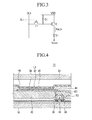
- FIG. 3 is a circuit schematic diagram of a sub-pixel of a panel assembly of FIG. 1 .
- FIG. 4 and FIG. 5 show partially exploded cross-sectional schematic views of the panel assembly of FIG. 1 .
- FIG. 6 is a top plan schematic view of an anode and a pixel defining layer in a configuration of the panel assembly of F1G. 5.
- FIG. 7 is a top plan schematic view of the anode and an organic emission layer in the configuration of the panel assembly of FIG. 5 .
- FIG. 8 is a partially exploded cross-sectional schematic view of a panel assembly in a configuration of a light emitting device according to a second exemplary embodiment of the present invention.
- FIG. 1 and FIG. 2 respectively show a perspective schematic view and a cross-sectional schematic view of an organic light emitting diode (OLED) display according to a first exemplary embodiment of the present invention.
- OLED organic light emitting diode
- an OLED display 100 includes a panel assembly 12, a flexible circuit board 14, and a printed circuit board 16.
- the panel assembly 12 includes a display area A10 and a pad area A20, and displays an image in the display area A10.
- the flexible circuit board 14 is fixed to the pad area A20, and the printed circuit board 16 is electrically connected with the panel assembly 12 through the flexible circuit board 14.
- the panel assembly 12 includes a first substrate 18 and a second substrate 22.
- the second substrate 22 is smaller than the first substrate 18 and of which an edge portion is attached to the first substrate 18 by a sealant 20 ( FIG. 2 ).
- the display area A10 is located in an area where the first and second substrates 18 and 22 are overlapped at a region defined by an interior side or sides of the sealant 20, and the pad area A20 is located on the first substrate 18 at an external side (i.e., a side facing away or oppositely away from the interior side) of the sealant 20.
- a plurality of sub-pixels are disposed in a matrix pattern in a display region on the display area A10 of the first substrate 18, and a scan driver and a data driver are located between the display area A10 and the sealant 20 or at the external side of the sealant 20 for driving the sub-pixels.
- a scan driver and a data driver are located between the display area A10 and the sealant 20 or at the external side of the sealant 20 for driving the sub-pixels.
- pad electrodes for transmitting electrical signals to the scan and data drivers are located in the pad area A20 of the first substrate 18.
- An integrated circuit chip 24 and the flexible circuit board 14 are mounted on the pad area A20 of the first substrate 18.
- a protective layer 26 is formed around the integrated circuit chip 24 and the flexible circuit board 14 to protect pad electrodes formed in the pad area A20 by covering them.
- Surface Mounted Devices are mounted on the printed circuit board 16 for passing driving signals, and a connector 28 is installed on the printed circuit board 16 for transmitting an external signal thereto.
- a bezel for increasing bending strength of the panel assembly 12 or a buffering tape for increasing impact resistance of the panel assembly 12 may be formed.
- the flexible circuit board 14 fixed to the pad area A20 is bent toward the rear side of the panel assembly 12 to make the printed circuit board 16 face the rear side of the panel assembly 12 as shown in FIG. 2 .
- F1G. 3 is a circuit schematic diagram of a sub-pixel of the panel assembly of FIG. 1
- FIG. 4 is a cross-sectional schematic view of the panel assembly of FIG. 1 .
- a sub-pixel of the panel assembly 12 is formed of an OLED L1 and a driving circuit unit.
- the OLED L1 includes an anode (hole injection electrode) 30, an organic emission layer 32, and a cathode (electron injection electrode) 34.
- the driving circuit unit includes at least two thin film transistors T1 and T2 and at least one storage capacitor C1.
- the at least two thin film transistors include a switching transistor T1, and a driving transistor T2.
- the switching transistor T1 is connected to a scan line SL1 and a data line DL1, and transmits a data voltage from the data line DL1 according to a switching voltage from the scan line SL1 to the driving transistor T2.
- the storage capacitor C1 is connected to the switching transistor T1 and a power source line VDD, and stores a voltage that corresponds to a difference of a voltage transmitted from the switching transistor T1 and a voltage supplied to the power source line VDD.
- the driving transistor T2 is connected to the power source line VDD and the storage capacitor C1 and supplies an output current I OLED that is proportional to a square of a difference between the voltage stored in the storage capacitor C1 and a threshold voltage to the OLED L1, and the OLED L1 emits light in accordance with the output current IDLED.
- the driving transistor T2 includes a source electrode 36, a drain electrode 38, and a gate electrode 40, and the anode 30 of the OLED L1 may be connected to the drain electrode 38 of the driving transistor T2.
- a planarization layer 42 is disposed on the source electrode 36 and the drain electrode 38 of the driving transistor T2, and the anode 30 is formed on the planarization layer 42.
- a via hole 421 is formed in the planarization layer 42, and the anode 30 is connected to the drain electrode 38 through the via hole 421.
- a pixel defining layer 44 is formed on the anode 30 and the planarization layer 42. The pixel defining layer 44 forms an opening 46 in a portion that overlaps the anode 30 in each sub-pixel to expose the anode 30.
- the organic emission layer 32 is filled in the opening of the pixel defining layer 44 and thus contacts the anode 30.
- the organic emission layer 32 may be formed to be the same size as or larger than the opening 46 of the pixel defining layer 44. That is, if the size (e.g., a surface area) of the organic emission layer 32 is larger than that of the opening 46 of the pixel defining layer 44, the organic emission layer 32 may be formed over a side wall of the fixed defining layer 44 at where the opening 46 is formed and an upper surface of the pixel defining layer 44. In FIG. 4 , as an example, the size of the organic emission layer 32 is substantially the same as that of the opening 46 of the pixel defining layer 44.
- the configuration of the sub-pixel is not limited thereto, and may be suitably modified.
- the anode 30 is formed as a metal layer having a light reflection characteristic, and the cathode 34 is formed as a transparent conductive layer. Therefore, light emitted from the organic emission layer 32 is emitted out of the panel assembly 12 through the cathode 34 and the second substrate 22, and the anode 30 reflects light emitted toward the first substrate 18 among the light emitted from the organic emission layer 32 to increase luminous efficiency. In this case, the anode 30 reflects not only light emitted from the organic emission layer 32, but also light transmitted from the outside (e.g., sunlight) and into the panel assembly 12.
- the outside e.g., sunlight
- the OLED display 100 of an exemplary embodiment can provide luminous efficiency while reducing or minimizing reflection of external light due to the anode 30.
- FIG. 5 is a partially enlarged cross-sectional schematic view of the panel assembly of FIG. 1
- FIG. 6 is a top plan schematic view of the anode and the pixel defining layer of FIG. 5
- FIG. 7 is a top plan schematic view of the anode and the organic emission layer of FIG. 5 .
- a pixel of the OLED display 100 includes a first sub-pixel SP1 including a first anode 301 and a first organic emission layer 321, a second sub-pixel SP2 including a second anode 302 and a second organic emission layer 322, and a third sub-pixel SP3 including a third anode 303 and a third organic emission layer 323.
- the cathode 34 is formed over the first to third sub-pixels SP1, SP2, and SP3 rather than being divided for each sub-pixel.
- the OLED display 100 has the first sub-pixel SP1 corresponding to a red color, the second sub-pixel SP2 corresponding to a green color, and the third sub-pixel SP3 corresponding to a blue color in order to realize a full-colored image.
- the first organic emission layer 321 is formed as an emission layer for the red color
- the second organic emission layer 322 is formed as an emission layer for the green color
- the third organic emission layer 323 is formed as an emission layer for the blue color.
- each color realized by each of the plurality of organic emission layers is not limited thereto, and it may be appropriately modified according to the realization purpose or configuration of the OLED display and a choice of a person having ordinary skill in the art.
- the pixel defining layer 44 includes a first opening 461 disposed in the first sub-pixel SP1, a second opening 462 disposed in the second sub-pixel SP2, and a third opening 463 disposed in the third sub-pixel SP3.
- the first to third anodes 301, 302, and 303 respectively have different widths, and the first to third openings 461, 462, and 463 also have different widths.
- the widths of the first to third anodes 301, 302, and 303 disposed along a direction (the y-axis in the drawing) traversing the first to third sub-pixels SP1, SP2, and SP3 are respectively denoted as W1, W2, and W3.
- the widths of the first to third openings 461, 462, and 462 disposed along a direction that is the same as that of the first to third anodes 301, 302, and 303 are respectively denoted as w1, w2, and w3.
- the widths of the first to third anodes 301, 302, and 303 and the widths of the first to third openings 461, 462, and 463 may be inversely proportional to luminance efficiency of the first to third organic emission layers 321, 322, and 323 respectively disposed in the corresponding sub-pixels. That is, an organic emission layer having the lowest luminous efficiency among the first to third organic emission layers 321, 322, and 323 may have a larger area in the pixel by increasing the width of the anode and the width of the opening than the widths of the corresponding anode and opening of organic emission layers having relatively higher luminous efficiency.
- the widths of the first to third anodes 301, 302, and 303 may be gradually decreased in the order of the third anode 303, the first anode 301, and the second anode 302, and the widths of the openings 461, 462, and 463 may also be gradually decreased in the order of the third opening 463, the first opening 461, and the second opening 462.
- the width W3 of the third anode 303 is larger than the width W1 of the first anode 301
- the width W1 of the first anode 301 is larger than the width W2 of the second anode 302.
- the width w3 of the third opening 463 is larger that the width w1 of the first opening 461, and the width w1 of the first opening 461 is larger than the width w2 of the second opening 462. Therefore, the size of the first, second, and third organic emission layers 321, 322, and 323 in one pixel may be gradually decreased in the order of the third organic emission layer 323, the first organic emission layer 321, and the second organic emission layer 322.
- the first to third anodes 301, 302, and 303 are formed wider than the openings 461, 462, and 463 of the pixel defining layer 44 of the corresponding sub-pixel so that the edge portions of the first to third anodes 301, 302, and 303 partially overlap the pixel defining layer 44.
- the edges of the openings 461, 462, and 463 of the pixel defining layer 44 are separated by a set or predetermined distance from the edges of the anodes 301, 302, and 303. Therefore, excluding a portion where the via hole 421 is formed, the overlapped portions w4 (refer to FIG. 6 ) of the first to third anodes 301, 302, and 303 and the pixel defining layer 44 may have a constant width.
- the first, second, and third organic emission layers 321, 322, and 323 may be formed to have the same or a greater width than the openings 461, 462, and 463 of a pixel defining layer 44 of the corresponding sub-pixel.
- the first to third organic emission layers 321, 322, and 323 are formed to be the same (or substantially the same) in size as the openings 461, 462, and 463 of the pixel defining layer of the corresponding sub-pixel.
- the first to third anodes 301, 302, and 303 satisfy the following condition 1.
- P denotes the width of a pixel.
- the first to third anodes 301, 302, and 303 and the pixel defining layer 44 satisfy the following condition 2. w ⁇ 1 + w ⁇ 2 + 12 ⁇ ⁇ m ⁇ W ⁇ 1 + W ⁇ 2
- Condition 2 implies that the width w4 of the overlapped portion of the first to third anodes 301, 302, and 303 and the pixel defining layer 44 is greater than 3 ⁇ m.
- condition 2 If condition 2 is not satisfied, the pattern quality of the pixel defining layer 44 is deteriorated when the openings 401, 462, and 463 of the pixel defining layer 44 are formed through the photolithography process so that the pixel defining layer 44 at the edge portions of the anodes 301, 302, and 303 may be damaged.
- the anodes 301, 302, and 303 may contact the cathode 34 at the edge portions of the anode 301, 302, and 303 such that an electrical short circuit may occur, thereby causing damage to the organic emission layers 321, 322, and 323.
- the width of each of the anodes 301, 302, and 303 is set to be different from each other for each sub-pixel according to efficiency of the organic emission layers 321, 322, and 323 while reducing or minimizing the width w4 of the overlapped portion of the anodes 301, 302, and 303 with the pixel defining layer 44.
Abstract

where W1, W2, and W3 respectively denote the width of the first anode (301), the width of the second anode (302), and the width of the third anode (303) measured along a direction traversing the first sub-pixel (SP1), the second sub-pixel (SP2), and the third sub-pixel (SP3) and where P denotes a width of the pixel measure along the direction traversing the first sub-pixel (SP1), the second sub-pixel (SP2), and the third sub-pixel (SP3).
Description
- The following description relates to an organic light emitting diode (OLED) display.
- Display quality of an OLED display is greatly influenced by external light. That is, when external light is transmitted into the OLED display that includes an OLED and a thin film transistor, reflection of the external light occurs in layers that form the OLED and the thin film transistor. For example, a metal layer used as an electrode of the OLED has high light reflectivity so that most of the external light can be reflected. The reflected external light is mixed with light emitted from an organic emission layer so that display visibility of the OLED display is deteriorated.
- An aspect of an embodiment of the present invention is directed toward an organic light emitting diode (OLED) display capable of reducing or minimizing reflection of external light to improve display visibility of the OLED display.
- An OLED display according to an exemplary embodiment of the present invention includes a pixel having first, second and third sub-pixels. The first sub-pixel has a first anode and a first organic emission layer, the second sub-pixel has a second anode and a second organic emission layer, and the third sub-pixel has a third anode and a third organic emission layer. The first, second, and third anodes satisfy the following condition:

where W1, W2, and W3 respectively denote a width of the first anode, a width of the second anode, and a width of the third anode measured along a direction traversing the first sub-pixel, the second sub-pixel, and the third sub-pixel and where P denotes a width of the pixel measured along the direction traversing the first sub-pixel, the second sub-pixel, and the third sub-pixel. - The OLED display may further include a pixel defining layer disposed on edge portions of the first, second, and third anodes. The pixel defining layer may form a first opening exposing a portion of the first anode, a second opening exposing a portion of the second anode, and a third opening exposing a portion of the third anode.
- The first anode, the second anode, the third anode, and the pixel defining layer may satisfy the following condition:

where w1 and w2 respectively denote a width of the first opening and a width of the second opening measured along the direction traversing the first, second, and third sub-pixels. - The widths of the first, second, and third anodes may be gradually decreased in the order of the third anode, the first anode, and the second anode. The widths of the first, second, and third openings may be gradually decreased in the order of the third opening, the first opening, and the second opening.
- The widths of the first, second, and third openings may be respectively smaller than those of the first, second, and third anodes. The edge portions of the first, second, and third anodes that are overlapped with the pixel defining layer may have a constant width. The constant width of each of the edge portions of the first, second, and third anodes that are overlapped with the pixel defining layer may be greater than 3µm.
- The second anode may include an externally extended via hole region, and the second organic emission layer may be formed on the second anode, excluding the via hole region.
- The OLED display may further include a black-colored planarization layer disposed in a lower portion of the first, second, and third anodes. In one embodiment, the first, second, and third anodes is between the black-colored planarization layer and the first, second, and third organic emission layers.
- The first organic emission layer may be an organic emission layer for a red color. The second organic emission layer may be an organic emission layer for a green color. The third organic emission layer may be an organic emission layer for a blue color.
-
FIG. 1 is a perspective schematic view of an OLED display according to a first exemplary embodiment of the present invention. -
FIG. 2 is a cross-sectional schematic view of the OLED display according to the first exemplary embodiment of the present invention. -
FIG. 3 is a circuit schematic diagram of a sub-pixel of a panel assembly ofFIG. 1 . -
FIG. 4 andFIG. 5 show partially exploded cross-sectional schematic views of the panel assembly ofFIG. 1 . -
FIG. 6 is a top plan schematic view of an anode and a pixel defining layer in a configuration of the panel assembly of F1G. 5. -
FIG. 7 is a top plan schematic view of the anode and an organic emission layer in the configuration of the panel assembly ofFIG. 5 . -
FIG. 8 is a partially exploded cross-sectional schematic view of a panel assembly in a configuration of a light emitting device according to a second exemplary embodiment of the present invention. - The present invention will be described more fully hereinafter with reference to the accompanying drawings, in which exemplary embodiments of the invention are shown.
-
FIG. 1 and FIG. 2 respectively show a perspective schematic view and a cross-sectional schematic view of an organic light emitting diode (OLED) display according to a first exemplary embodiment of the present invention. - Referring to
FIG. 1 and FIG. 2 , anOLED display 100 according to the present exemplary embodiment includes apanel assembly 12, aflexible circuit board 14, and a printedcircuit board 16. Thepanel assembly 12 includes a display area A10 and a pad area A20, and displays an image in the display area A10. Theflexible circuit board 14 is fixed to the pad area A20, and the printedcircuit board 16 is electrically connected with thepanel assembly 12 through theflexible circuit board 14. - The
panel assembly 12 includes afirst substrate 18 and asecond substrate 22. Thesecond substrate 22 is smaller than thefirst substrate 18 and of which an edge portion is attached to thefirst substrate 18 by a sealant 20 (FIG. 2 ). The display area A10 is located in an area where the first andsecond substrates sealant 20, and the pad area A20 is located on thefirst substrate 18 at an external side (i.e., a side facing away or oppositely away from the interior side) of thesealant 20. - A plurality of sub-pixels are disposed in a matrix pattern in a display region on the display area A10 of the
first substrate 18, and a scan driver and a data driver are located between the display area A10 and thesealant 20 or at the external side of thesealant 20 for driving the sub-pixels. In the pad area A20 of thefirst substrate 18, pad electrodes for transmitting electrical signals to the scan and data drivers are located. - An
integrated circuit chip 24 and theflexible circuit board 14 are mounted on the pad area A20 of thefirst substrate 18. Aprotective layer 26 is formed around the integratedcircuit chip 24 and theflexible circuit board 14 to protect pad electrodes formed in the pad area A20 by covering them. Surface Mounted Devices are mounted on the printedcircuit board 16 for passing driving signals, and aconnector 28 is installed on the printedcircuit board 16 for transmitting an external signal thereto. - In a rear side of the
panel assembly 12, a bezel for increasing bending strength of thepanel assembly 12 or a buffering tape for increasing impact resistance of thepanel assembly 12 may be formed. Theflexible circuit board 14 fixed to the pad area A20 is bent toward the rear side of thepanel assembly 12 to make the printedcircuit board 16 face the rear side of thepanel assembly 12 as shown inFIG. 2 . - F1G. 3 is a circuit schematic diagram of a sub-pixel of the panel assembly of
FIG. 1 , andFIG. 4 is a cross-sectional schematic view of the panel assembly ofFIG. 1 . - Referring to
FIG. 3 and FIG. 4 , a sub-pixel of thepanel assembly 12 is formed of an OLED L1 and a driving circuit unit. The OLED L1 includes an anode (hole injection electrode) 30, anorganic emission layer 32, and a cathode (electron injection electrode) 34. Here, the driving circuit unit includes at least two thin film transistors T1 and T2 and at least one storage capacitor C1. Here, in one embodiment, the at least two thin film transistors include a switching transistor T1, and a driving transistor T2. - The switching transistor T1 is connected to a scan line SL1 and a data line DL1, and transmits a data voltage from the data line DL1 according to a switching voltage from the scan line SL1 to the driving transistor T2. The storage capacitor C1 is connected to the switching transistor T1 and a power source line VDD, and stores a voltage that corresponds to a difference of a voltage transmitted from the switching transistor T1 and a voltage supplied to the power source line VDD.
- The driving transistor T2 is connected to the power source line VDD and the storage capacitor C1 and supplies an output current IOLED that is proportional to a square of a difference between the voltage stored in the storage capacitor C1 and a threshold voltage to the OLED L1, and the OLED L1 emits light in accordance with the output current IDLED. As shown in
FIG. 4 , the driving transistor T2 includes asource electrode 36, adrain electrode 38, and agate electrode 40, and theanode 30 of the OLED L1 may be connected to thedrain electrode 38 of the driving transistor T2. - A
planarization layer 42 is disposed on thesource electrode 36 and thedrain electrode 38 of the driving transistor T2, and theanode 30 is formed on theplanarization layer 42. Avia hole 421 is formed in theplanarization layer 42, and theanode 30 is connected to thedrain electrode 38 through thevia hole 421. Apixel defining layer 44 is formed on theanode 30 and theplanarization layer 42. Thepixel defining layer 44 forms anopening 46 in a portion that overlaps theanode 30 in each sub-pixel to expose theanode 30. In addition, theorganic emission layer 32 is filled in the opening of thepixel defining layer 44 and thus contacts theanode 30. - The
organic emission layer 32 may be formed to be the same size as or larger than theopening 46 of thepixel defining layer 44. That is, if the size (e.g., a surface area) of theorganic emission layer 32 is larger than that of theopening 46 of thepixel defining layer 44, theorganic emission layer 32 may be formed over a side wall of the fixed defininglayer 44 at where theopening 46 is formed and an upper surface of thepixel defining layer 44. InFIG. 4 , as an example, the size of theorganic emission layer 32 is substantially the same as that of theopening 46 of thepixel defining layer 44. The configuration of the sub-pixel is not limited thereto, and may be suitably modified. - In the previously described OLED L1, the
anode 30 is formed as a metal layer having a light reflection characteristic, and thecathode 34 is formed as a transparent conductive layer. Therefore, light emitted from theorganic emission layer 32 is emitted out of thepanel assembly 12 through thecathode 34 and thesecond substrate 22, and theanode 30 reflects light emitted toward thefirst substrate 18 among the light emitted from theorganic emission layer 32 to increase luminous efficiency. In this case, theanode 30 reflects not only light emitted from theorganic emission layer 32, but also light transmitted from the outside (e.g., sunlight) and into thepanel assembly 12. - According to the following configuration of the
anode 30, theOLED display 100 of an exemplary embodiment can provide luminous efficiency while reducing or minimizing reflection of external light due to theanode 30. -
FIG. 5 is a partially enlarged cross-sectional schematic view of the panel assembly ofFIG. 1 ,FIG. 6 is a top plan schematic view of the anode and the pixel defining layer ofFIG. 5 , andFIG. 7 is a top plan schematic view of the anode and the organic emission layer ofFIG. 5 . - Referring to
FIG. 5 to FIG. 7 , a pixel of theOLED display 100 includes a first sub-pixel SP1 including afirst anode 301 and a firstorganic emission layer 321, a second sub-pixel SP2 including asecond anode 302 and a secondorganic emission layer 322, and a third sub-pixel SP3 including athird anode 303 and a thirdorganic emission layer 323. Thecathode 34 is formed over the first to third sub-pixels SP1, SP2, and SP3 rather than being divided for each sub-pixel. - In the first exemplary embodiment, the
OLED display 100 has the first sub-pixel SP1 corresponding to a red color, the second sub-pixel SP2 corresponding to a green color, and the third sub-pixel SP3 corresponding to a blue color in order to realize a full-colored image. Accordingly, the firstorganic emission layer 321 is formed as an emission layer for the red color, the secondorganic emission layer 322 is formed as an emission layer for the green color, and the thirdorganic emission layer 323 is formed as an emission layer for the blue color. However, each color realized by each of the plurality of organic emission layers is not limited thereto, and it may be appropriately modified according to the realization purpose or configuration of the OLED display and a choice of a person having ordinary skill in the art. - The
pixel defining layer 44 includes afirst opening 461 disposed in the first sub-pixel SP1, asecond opening 462 disposed in the second sub-pixel SP2, and athird opening 463 disposed in the third sub-pixel SP3. The first tothird anodes third openings - In
FIG. 6 , the widths of the first tothird anodes third openings third anodes - The widths of the first to
third anodes third openings - The widths of the first to
third anodes third anode 303, thefirst anode 301, and thesecond anode 302, and the widths of theopenings third opening 463, thefirst opening 461, and thesecond opening 462. To put it another way, the width W3 of thethird anode 303 is larger than the width W1 of thefirst anode 301, and the width W1 of thefirst anode 301 is larger than the width W2 of thesecond anode 302. In addition, the width w3 of thethird opening 463 is larger that the width w1 of thefirst opening 461, and the width w1 of thefirst opening 461 is larger than the width w2 of thesecond opening 462. Therefore, the size of the first, second, and third organic emission layers 321, 322, and 323 in one pixel may be gradually decreased in the order of the thirdorganic emission layer 323, the firstorganic emission layer 321, and the secondorganic emission layer 322. - In addition, the first to
third anodes openings pixel defining layer 44 of the corresponding sub-pixel so that the edge portions of the first tothird anodes pixel defining layer 44. In this case, excluding a portion where the viahole 421 is formed, the edges of theopenings pixel defining layer 44 are separated by a set or predetermined distance from the edges of theanodes hole 421 is formed, the overlapped portions w4 (refer toFIG. 6 ) of the first tothird anodes pixel defining layer 44 may have a constant width. - The first, second, and third organic emission layers 321, 322, and 323 may be formed to have the same or a greater width than the
openings pixel defining layer 44 of the corresponding sub-pixel. InFIG. 7 , the first to third organic emission layers 321, 322, and 323 are formed to be the same (or substantially the same) in size as theopenings - In the
OLED display 100 according to the present exemplary embodiment, the first tothird anodes 
- Here, P denotes the width of a pixel.
- In condition 1, if the sum of W1 and W2 is more than two times W3, the
third anode 303 and the thirdorganic emission layer 323 does not have sufficient areas in the pixel so that luminance efficiency of the thirdorganic emission layer 323 cannot be increased. In addition, if twice W3 is more than two thirds the pixel width P in condition 1, the areas of the first andsecond anodes organic emission layers organic emission layers - In addition, in the
OLED display 100 according to the present exemplary embodiment, the first tothird anodes pixel defining layer 44 satisfy thefollowing condition 2.
-
Condition 2 implies that the width w4 of the overlapped portion of the first tothird anodes pixel defining layer 44 is greater than 3µm. - If
condition 2 is not satisfied, the pattern quality of thepixel defining layer 44 is deteriorated when theopenings pixel defining layer 44 are formed through the photolithography process so that thepixel defining layer 44 at the edge portions of theanodes anodes cathode 34 at the edge portions of theanode - Since the
OLED display 100 according to the present exemplary embodiment satisfiescondition 2, the electrical short circuit between theanodes cathode 34 and the damage to the organic emission layers 321, 322, and 323 can be suppressed. - As described, in the
OLED display 100 according to the present exemplary embodiment, the width of each of theanodes anodes pixel defining layer 44. - Therefore, when light is emitted from the organic emission layers 321, 322, and 323 of the corresponding sub-pixel, the first to
third anodes pixel defining layer 44 while increasing efficiency of reflection toward thesecond substrate 22. Accordingly, theOLED display 100 according to the present exemplary embodiment can improve visibility by decreasing reflection of external light (by decreasing or minimizing width w4). - In the above-described sub-pixel configuration, the first to third organic emission layers 321, 322, and 323 may be formed in such a configuration that one or more of these
layers holes 421 by being patterned so that the planarity of the organic emission layers 321, 322, and 323 and thecathode 34 can be increased. - For example, the first and
third anodes third anodes hole 421 may be formed inside thereof. In addition, the first and thirdorganic emission layers holes 421. - On the other hand, the
second anode 302 having the smallest width and area among the first tothird anodes FIG. 7 ). The viahole 421 here is disposed in the viahole region 50, and the secondorganic emission layer 322 may be formed in a rectangular shape on thesecond anode electrode 302, excluding the viahole region 50. Therefore, sufficient patterning space can be easily obtained in the second sub-pixel having the smallest width and area. To put it another way, in the embodiment as shown, each of the first andthird anodes second anode 302 has a polygonal shape region and the externally extended via hole region extending out of the polygonal shape region, and the secondorganic emission layer 322 is formed only on the polygonal shape region of thesecond anode 302. -
FIG. 8 is a partially enlarged cross-sectional view of a panel assembly in a configuration of a light emitting device according to a second exemplary embodiment of the present invention. - Referring to
FIG. 8 , anOLED display 101 according to the present exemplary embodiment is the same as the OLED display of the first exemplary embodiment, excluding that a planarization layer 42' is formed of a black-colored material that absorbs light. Like reference numerals are used for like elements of the first exemplary embodiment. - The planarization layer 42' may be formed as a black-colored acryl-based material. The black planarization layer 42' absorbs external light transmitted to portions between
anodes OLED display 101 of the second exemplary embodiment can further decrease reflection of external light compared to theOLED 100 of the first exemplary embodiment so that outdoor display visibility can be improved. - The following Table 1 shows reflectance of external light of an OLED display of a comparative example, the OLED display of the first exemplary embodiment, and the OLED display of the second exemplary embodiment, measured through computer simulation. The OLED display of the comparative example includes anodes each having the same width measured along the direction traversing the first to third sub-pixels, and is the same (or substantially the same) as the OLED display of the first exemplary embodiment, excluding the shape of the anodes.
(Table 1) Reflectance of external light Comparative example 40.8% First exemplary embodiment 37.2% Second exemplary embodiment 36.4% - Simulation measurement of the reflectance of external light is performed through a comparative experiment of reflectance of external light of a standard reflection plate and reflectance of external light of the experiment subject under a condition of using the same standard light source. The reflectance of external light in the table is a calculated value of a comparative value to the reflectance of external light of the standard reflection plate under an assumption that the reflectance of external light of the standard reflection plate is 100.
- As shown in the table, the reflectance of the external light can be decreased more in the OLED display of the first and second exemplary embodiments where the widths of the anodes is varied than in the OLED display of the comparative example where the widths of the anodes are the same in first to third sub-pixels, and particularly, the reflectance of the external light is decreased by a maximum of 4.4% in the OLED display of the second exemplary embodiment where the black planarization layer is formed.
- As such and in view of the foregoing, the OLED display according to an embodiment of the present invention can improve outdoor visibility by reducing or minimizing reflection of external light due to anodes. In addition, the planarization layer according to an embodiment of the present invention is formed as a black-colored material so that external light transmitted to portions between the anodes can be absorbed by the black planarization layer, thereby further improving the outdoor visibility.
Claims (14)
- An organic light emitting diode (OLED) display comprising a pixel having first, second and third sub-pixels,
the first sub-pixel comprising a first anode and a first organic emission layer, the second sub-pixel comprising a second anode and a second organic emission layer and the third sub-pixel comprising a third anode and a third organic emission layer, characterized in that the first anode, the second anode, and the third anode satisfy the following condition:
wherein W1, W2, and W3 respectively denote a width of the first anode, a width of the second anode, and a width of the third anode measured along a direction traversing the first sub-pixel, the second sub-pixel, and the third sub-pixel, and wherein P denotes a width of the pixel measured along the direction traversing the first sub-pixel, the second sub-pixel, and the third sub-pixel. - The OLED display of claim 1, further comprising a pixel defining layer disposed on edge portions of the first, second, and third anodes and having a first opening exposing a portion of the first anode, a second opening exposing a portion of the second anode, and a third opening exposing a portion of the third anode.
- The OLED display of claim 2, wherein the first anode, the second anode, the third anode, and the pixel defining layer satisfy the following condition:

wherein w1 and w2 respectively denote a width of the first opening and a width of the second opening measured along the direction traversing the first, second, third sub-pixels. - The OLED display of one of the preceding claims, wherein the width of the third anode is larger than the width of the first anode, and the width of the first anode is larger than the width of the second anode.
- The OLED display of claim 3 or of claim 4 as dependent on claim 3, wherein the width of the third opening is larger that the width of the first opening, and the width of the first opening is larger than the width of the second opening.
- The OLED display of claim 5, wherein the widths of the first, second, and third openings are respectively smaller than those of the first, second, and third anodes, and the edge portions of the first, second, and third anodes that are overlapped with the pixel defining layer have a constant width.
- The OLED display of claim 6, wherein the constant width of each of the edge portions of the first, second, and third anodes that are overlapped with the pixel defining layer is greater than 3µm.
- The OLED display of claim 6, wherein the second anode comprises an externally extended via hole region, and the second organic emission layer is on the second anode, excluding the via hole region.
- The OLED display of claim 6, wherein each of the first and third anodes has a polygonal shape region and a via hole region therein, and each of the first and third organic emission layers has a partially concave portion at the via hole region.
- The OLED display of claim 9, wherein the second anode has a polygonal shape region and an externally extended via hole region extending out of the polygonal shape region, and the second organic emission layer is only on the polygonal shape region of the second anode.
- The OLED display of one of the preceding claims, further comprising a black-colored planarization layer, wherein the first, second, and third anodes are arranged between the black-colored planarization layer and the first, second, and third organic emission layers.
- The OLED display of one of the preceding claims, wherein the first organic emission layer is an organic emission layer for a red color.
- The OLED display of one of the preceding claims, wherein the second organic emission layer is an organic emission layer for a green color.
- The OLED display of one of the preceding claims, wherein the third organic emission layer is an organic emission layer for a blue color.
Applications Claiming Priority (1)
| Application Number | Priority Date | Filing Date | Title |
|---|---|---|---|
| KR1020090023646A KR101023133B1 (en) | 2009-03-19 | 2009-03-19 | Organic light emitting diode display |
Publications (2)
| Publication Number | Publication Date |
|---|---|
| EP2230692A1 true EP2230692A1 (en) | 2010-09-22 |
| EP2230692B1 EP2230692B1 (en) | 2013-05-15 |
Family
ID=42269627
Family Applications (1)
| Application Number | Title | Priority Date | Filing Date |
|---|---|---|---|
| EP10156910.1A Active EP2230692B1 (en) | 2009-03-19 | 2010-03-18 | Organic light emitting diode display |
Country Status (5)
| Country | Link |
|---|---|
| US (1) | US8569947B2 (en) |
| EP (1) | EP2230692B1 (en) |
| JP (1) | JP2010225587A (en) |
| KR (1) | KR101023133B1 (en) |
| CN (1) | CN101840930B (en) |
Cited By (1)
| Publication number | Priority date | Publication date | Assignee | Title |
|---|---|---|---|---|
| US20120176025A1 (en) * | 2011-01-10 | 2012-07-12 | Samsung Mobile Display Co., Ltd. | Organic Light Emitting Display Apparatus and Method of Manufacturing the Same |
Families Citing this family (22)
| Publication number | Priority date | Publication date | Assignee | Title |
|---|---|---|---|---|
| KR101632298B1 (en) * | 2012-07-16 | 2016-06-22 | 삼성디스플레이 주식회사 | Flat panel display device and manufacturing method thereof |
| US9170665B2 (en) * | 2012-09-14 | 2015-10-27 | Universal Display Corporation | Lifetime OLED display |
| US9257665B2 (en) | 2012-09-14 | 2016-02-09 | Universal Display Corporation | Lifetime OLED display |
| TWI559064B (en) | 2012-10-19 | 2016-11-21 | Japan Display Inc | Display device |
| JP6116241B2 (en) * | 2012-12-28 | 2017-04-19 | ユニ・チャーム株式会社 | Stretchable sheet manufacturing apparatus and manufacturing method |
| CN103219359A (en) * | 2013-03-29 | 2013-07-24 | 京东方科技集团股份有限公司 | Organic electroluminescent array substrate and manufacturing method thereof, display device |
| KR102047006B1 (en) * | 2013-06-07 | 2019-12-03 | 삼성디스플레이 주식회사 | Organic luminescence emitting display device |
| KR102083985B1 (en) * | 2013-07-01 | 2020-03-04 | 삼성디스플레이 주식회사 | Organic light emitting diode and method for preparing the same |
| KR102150080B1 (en) * | 2013-09-12 | 2020-09-01 | 삼성디스플레이 주식회사 | Display panel and display device having the same |
| US20170069697A1 (en) * | 2014-05-23 | 2017-03-09 | Joled Inc. | Organic el display panel and organic el display device |
| KR102141208B1 (en) * | 2014-06-30 | 2020-08-05 | 삼성디스플레이 주식회사 | Portable electronic apparatus |
| KR20160130048A (en) * | 2015-04-30 | 2016-11-10 | 삼성디스플레이 주식회사 | Organic light-emitting display apparatus |
| JP6768394B2 (en) * | 2016-07-29 | 2020-10-14 | 株式会社ジャパンディスプレイ | Electronics |
| KR20180021286A (en) * | 2016-08-18 | 2018-03-02 | 삼성디스플레이 주식회사 | Display device and manufacturing method thereof |
| JP2018049805A (en) * | 2016-09-23 | 2018-03-29 | 東京エレクトロン株式会社 | Coating device, coating method, and organic el display |
| CN106953025B (en) * | 2017-02-22 | 2018-10-12 | 信利(惠州)智能显示有限公司 | The manufacturing method of organic light-emitting display device |
| KR102439873B1 (en) * | 2017-03-10 | 2022-09-05 | 삼성디스플레이 주식회사 | Organic light-emitting apparatus and the method for manufacturing of the organic light-emitting display apparatus |
| KR102411145B1 (en) * | 2017-04-19 | 2022-06-20 | 삼성디스플레이 주식회사 | Head mounted display device |
| CN108364983A (en) * | 2018-02-01 | 2018-08-03 | 武汉华星光电半导体显示技术有限公司 | Pixel arrangement structure |
| KR102619291B1 (en) | 2018-11-28 | 2023-12-28 | 엘지디스플레이 주식회사 | Display device |
| KR20200089379A (en) * | 2019-01-16 | 2020-07-27 | 삼성디스플레이 주식회사 | Organic light emitting display apparatus |
| CN113097417B (en) * | 2021-03-30 | 2023-04-18 | 云南创视界光电科技有限公司 | OLED display substrate and display device |
Citations (6)
| Publication number | Priority date | Publication date | Assignee | Title |
|---|---|---|---|---|
| EP1032045A2 (en) * | 1999-02-26 | 2000-08-30 | SANYO ELECTRIC Co., Ltd. | Electroluminescence display apparatus |
| JP2003076301A (en) * | 2001-09-07 | 2003-03-14 | Matsushita Electric Ind Co Ltd | Light emitting element and display device using the element |
| EP1381095A2 (en) * | 2002-07-10 | 2004-01-14 | Kabushiki Kaisha Toyota Jidoshokki | Color display |
| US20050218792A1 (en) * | 2004-03-31 | 2005-10-06 | Samsung Electronics Co., Ltd. | Display device and method of manufacturing the same |
| US20060022587A1 (en) * | 2004-06-04 | 2006-02-02 | Chang-Yong Jeong | Electroluminescent display device and method of fabricating the same |
| US20080299496A1 (en) * | 2007-06-01 | 2008-12-04 | Semiconductor Energy Laboratory Co., Ltd. | Manufacturing Apparatus and Manufacturing Method of Light-Emitting Device |
Family Cites Families (19)
| Publication number | Priority date | Publication date | Assignee | Title |
|---|---|---|---|---|
| JP3670923B2 (en) * | 1999-02-26 | 2005-07-13 | 三洋電機株式会社 | Color organic EL display device |
| JP2002208485A (en) | 2001-01-09 | 2002-07-26 | Hitachi Ltd | Organic el display |
| TW589922B (en) * | 2001-09-19 | 2004-06-01 | Toshiba Corp | Self-emitting display apparatus |
| JP2003168561A (en) * | 2001-09-19 | 2003-06-13 | Toshiba Corp | Self-light emitting display device |
| KR100467553B1 (en) * | 2002-05-21 | 2005-01-24 | 엘지.필립스 엘시디 주식회사 | electroluminescent display device and fabrication method of the same |
| TW594637B (en) * | 2002-09-13 | 2004-06-21 | Sanyo Electric Co | Electroluminescence display device and method of pattern layout for the electroluminescence display device |
| JP4502661B2 (en) * | 2003-02-20 | 2010-07-14 | 三洋電機株式会社 | Color light emitting display device |
| US6919681B2 (en) * | 2003-04-30 | 2005-07-19 | Eastman Kodak Company | Color OLED display with improved power efficiency |
| JP2006019233A (en) * | 2003-07-30 | 2006-01-19 | Asahi Glass Co Ltd | Organic el display element and its manufacturing method |
| KR100626284B1 (en) * | 2003-11-19 | 2006-09-21 | 엘지.필립스 엘시디 주식회사 | Organic Electro Luminescence Device And Fabricating Method Thereof |
| JP2005222928A (en) * | 2004-01-07 | 2005-08-18 | Seiko Epson Corp | Electro-optical device |
| JP4731970B2 (en) * | 2004-04-07 | 2011-07-27 | 株式会社半導体エネルギー研究所 | Light emitting device and manufacturing method thereof |
| KR20060104531A (en) * | 2005-03-30 | 2006-10-09 | 삼성에스디아이 주식회사 | The manufacturing method of light emission device |
| KR101219036B1 (en) * | 2005-05-02 | 2013-01-07 | 삼성디스플레이 주식회사 | Organic light emitting diode display |
| JP2007042443A (en) * | 2005-08-03 | 2007-02-15 | Toshiba Matsushita Display Technology Co Ltd | Indicating device |
| JP2007095609A (en) * | 2005-09-30 | 2007-04-12 | Seiko Epson Corp | Light emitting device and electronic apparatus |
| US8130177B2 (en) * | 2008-03-13 | 2012-03-06 | Panasonic Corporation | Organic EL display panel and manufacturing method thereof |
| JP4428458B2 (en) * | 2008-08-29 | 2010-03-10 | セイコーエプソン株式会社 | Display device |
| JP5195593B2 (en) * | 2009-04-01 | 2013-05-08 | セイコーエプソン株式会社 | ORGANIC EL DEVICE, METHOD FOR MANUFACTURING ORGANIC EL DEVICE, AND ELECTRONIC DEVICE |
-
2009
- 2009-03-19 KR KR1020090023646A patent/KR101023133B1/en active IP Right Grant
-
2010
- 2010-03-10 JP JP2010053007A patent/JP2010225587A/en active Pending
- 2010-03-16 US US12/725,306 patent/US8569947B2/en active Active
- 2010-03-18 EP EP10156910.1A patent/EP2230692B1/en active Active
- 2010-03-18 CN CN2010101425782A patent/CN101840930B/en active Active
Patent Citations (6)
| Publication number | Priority date | Publication date | Assignee | Title |
|---|---|---|---|---|
| EP1032045A2 (en) * | 1999-02-26 | 2000-08-30 | SANYO ELECTRIC Co., Ltd. | Electroluminescence display apparatus |
| JP2003076301A (en) * | 2001-09-07 | 2003-03-14 | Matsushita Electric Ind Co Ltd | Light emitting element and display device using the element |
| EP1381095A2 (en) * | 2002-07-10 | 2004-01-14 | Kabushiki Kaisha Toyota Jidoshokki | Color display |
| US20050218792A1 (en) * | 2004-03-31 | 2005-10-06 | Samsung Electronics Co., Ltd. | Display device and method of manufacturing the same |
| US20060022587A1 (en) * | 2004-06-04 | 2006-02-02 | Chang-Yong Jeong | Electroluminescent display device and method of fabricating the same |
| US20080299496A1 (en) * | 2007-06-01 | 2008-12-04 | Semiconductor Energy Laboratory Co., Ltd. | Manufacturing Apparatus and Manufacturing Method of Light-Emitting Device |
Cited By (2)
| Publication number | Priority date | Publication date | Assignee | Title |
|---|---|---|---|---|
| US20120176025A1 (en) * | 2011-01-10 | 2012-07-12 | Samsung Mobile Display Co., Ltd. | Organic Light Emitting Display Apparatus and Method of Manufacturing the Same |
| US8258691B2 (en) * | 2011-01-10 | 2012-09-04 | Samsung Mobile Display Co., Ltd. | Organic light emitting display apparatus and method of manufacturing the same |
Also Published As
| Publication number | Publication date |
|---|---|
| US20100238096A1 (en) | 2010-09-23 |
| CN101840930A (en) | 2010-09-22 |
| KR20100104921A (en) | 2010-09-29 |
| JP2010225587A (en) | 2010-10-07 |
| CN101840930B (en) | 2012-05-09 |
| US8569947B2 (en) | 2013-10-29 |
| KR101023133B1 (en) | 2011-03-18 |
| EP2230692B1 (en) | 2013-05-15 |
Similar Documents
| Publication | Publication Date | Title |
|---|---|---|
| EP2230692B1 (en) | Organic light emitting diode display | |
| CN111710707B (en) | Display panel and display device | |
| KR101288427B1 (en) | Display substrate and method for manufacturing thereof | |
| KR100741968B1 (en) | Organic light emitting display device and fabricating method of the same | |
| US7946897B2 (en) | Dual panel type organic electroluminescent display device and method of fabricating the same | |
| KR20170023300A (en) | Transparent display pannel transparent display device including the same | |
| KR100653265B1 (en) | Dual Panel Type Organic Electroluminescent Device and Method for Fabricating the same | |
| US11309379B2 (en) | Organic light emitting diode display device including a power supply wire | |
| US20210399081A1 (en) | Transparent display device | |
| KR20150057407A (en) | Organic Light Emitting Display Device | |
| KR20170012664A (en) | Thin Film Transistor Array Substrate And Organic Light Emitting Diode Display Device Including The Same | |
| US7446741B2 (en) | Active matrix organic electroluminescent display device and method of fabricating the same | |
| KR20200119581A (en) | Display panel and method of manufacturing thereof | |
| US20220181355A1 (en) | Array substrate, display panel, and display device | |
| KR20150125207A (en) | Organic light emitting display and method of manufacturing the same | |
| CN114664895A (en) | Transparent display device | |
| JP2005128310A (en) | Display arrangement and electronic device | |
| KR101227134B1 (en) | Organic electroluminescent device | |
| CN111403460A (en) | O L ED display panel and display device | |
| KR101132183B1 (en) | Organic electroluminescent display device | |
| JP2007188853A (en) | Display device | |
| US20230207318A1 (en) | Display panel, tiled display device including the same, and method of manufacturing display panel | |
| US20240114737A1 (en) | Display panel and display device | |
| KR100579550B1 (en) | Dual Plate Type Organic Electroluminescent Display Device | |
| US20220190059A1 (en) | Transparent display device |
Legal Events
| Date | Code | Title | Description |
|---|---|---|---|
| PUAI | Public reference made under article 153(3) epc to a published international application that has entered the european phase |
Free format text: ORIGINAL CODE: 0009012 |
|
| 17P | Request for examination filed |
Effective date: 20100318 |
|
| AK | Designated contracting states |
Kind code of ref document: A1 Designated state(s): AT BE BG CH CY CZ DE DK EE ES FI FR GB GR HR HU IE IS IT LI LT LU LV MC MK MT NL NO PL PT RO SE SI SK SM TR |
|
| AX | Request for extension of the european patent |
Extension state: AL BA ME RS |
|
| 17Q | First examination report despatched |
Effective date: 20120625 |
|
| RAP1 | Party data changed (applicant data changed or rights of an application transferred) |
Owner name: SAMSUNG DISPLAY CO., LTD. |
|
| GRAP | Despatch of communication of intention to grant a patent |
Free format text: ORIGINAL CODE: EPIDOSNIGR1 |
|
| GRAS | Grant fee paid |
Free format text: ORIGINAL CODE: EPIDOSNIGR3 |
|
| GRAA | (expected) grant |
Free format text: ORIGINAL CODE: 0009210 |
|
| AK | Designated contracting states |
Kind code of ref document: B1 Designated state(s): AT BE BG CH CY CZ DE DK EE ES FI FR GB GR HR HU IE IS IT LI LT LU LV MC MK MT NL NO PL PT RO SE SI SK SM TR |
|
| REG | Reference to a national code |
Ref country code: CH Ref legal event code: EP Ref country code: GB Ref legal event code: FG4D |
|
| RIN1 | Information on inventor provided before grant (corrected) |
Inventor name: JEONG, HEE-SEONG Inventor name: JUNG, WOO-SUK Inventor name: LEE, JOO-HWA Inventor name: KIM, EUN-AH Inventor name: KWAK, NOH-MIN Inventor name: PARK, SOON-RYONG Inventor name: JEONG, CHUL-WOO Inventor name: JEON, HEE-CHUL |
|
| REG | Reference to a national code |
Ref country code: AT Ref legal event code: REF Ref document number: 612520 Country of ref document: AT Kind code of ref document: T Effective date: 20130615 |
|
| REG | Reference to a national code |
Ref country code: IE Ref legal event code: FG4D |
|
| REG | Reference to a national code |
Ref country code: DE Ref legal event code: R096 Ref document number: 602010007034 Country of ref document: DE Effective date: 20130711 |
|
| REG | Reference to a national code |
Ref country code: AT Ref legal event code: MK05 Ref document number: 612520 Country of ref document: AT Kind code of ref document: T Effective date: 20130515 |
|
| REG | Reference to a national code |
Ref country code: LT Ref legal event code: MG4D |
|
| REG | Reference to a national code |
Ref country code: NL Ref legal event code: VDEP Effective date: 20130515 |
|
| PG25 | Lapsed in a contracting state [announced via postgrant information from national office to epo] |
Ref country code: SE Free format text: LAPSE BECAUSE OF FAILURE TO SUBMIT A TRANSLATION OF THE DESCRIPTION OR TO PAY THE FEE WITHIN THE PRESCRIBED TIME-LIMIT Effective date: 20130515 Ref country code: PT Free format text: LAPSE BECAUSE OF FAILURE TO SUBMIT A TRANSLATION OF THE DESCRIPTION OR TO PAY THE FEE WITHIN THE PRESCRIBED TIME-LIMIT Effective date: 20130916 Ref country code: FI Free format text: LAPSE BECAUSE OF FAILURE TO SUBMIT A TRANSLATION OF THE DESCRIPTION OR TO PAY THE FEE WITHIN THE PRESCRIBED TIME-LIMIT Effective date: 20130515 Ref country code: NO Free format text: LAPSE BECAUSE OF FAILURE TO SUBMIT A TRANSLATION OF THE DESCRIPTION OR TO PAY THE FEE WITHIN THE PRESCRIBED TIME-LIMIT Effective date: 20130815 Ref country code: GR Free format text: LAPSE BECAUSE OF FAILURE TO SUBMIT A TRANSLATION OF THE DESCRIPTION OR TO PAY THE FEE WITHIN THE PRESCRIBED TIME-LIMIT Effective date: 20130816 Ref country code: ES Free format text: LAPSE BECAUSE OF FAILURE TO SUBMIT A TRANSLATION OF THE DESCRIPTION OR TO PAY THE FEE WITHIN THE PRESCRIBED TIME-LIMIT Effective date: 20130826 Ref country code: IS Free format text: LAPSE BECAUSE OF FAILURE TO SUBMIT A TRANSLATION OF THE DESCRIPTION OR TO PAY THE FEE WITHIN THE PRESCRIBED TIME-LIMIT Effective date: 20130915 Ref country code: AT Free format text: LAPSE BECAUSE OF FAILURE TO SUBMIT A TRANSLATION OF THE DESCRIPTION OR TO PAY THE FEE WITHIN THE PRESCRIBED TIME-LIMIT Effective date: 20130515 Ref country code: SI Free format text: LAPSE BECAUSE OF FAILURE TO SUBMIT A TRANSLATION OF THE DESCRIPTION OR TO PAY THE FEE WITHIN THE PRESCRIBED TIME-LIMIT Effective date: 20130515 Ref country code: LT Free format text: LAPSE BECAUSE OF FAILURE TO SUBMIT A TRANSLATION OF THE DESCRIPTION OR TO PAY THE FEE WITHIN THE PRESCRIBED TIME-LIMIT Effective date: 20130515 |
|
| PG25 | Lapsed in a contracting state [announced via postgrant information from national office to epo] |
Ref country code: HR Free format text: LAPSE BECAUSE OF FAILURE TO SUBMIT A TRANSLATION OF THE DESCRIPTION OR TO PAY THE FEE WITHIN THE PRESCRIBED TIME-LIMIT Effective date: 20130515 Ref country code: PL Free format text: LAPSE BECAUSE OF FAILURE TO SUBMIT A TRANSLATION OF THE DESCRIPTION OR TO PAY THE FEE WITHIN THE PRESCRIBED TIME-LIMIT Effective date: 20130515 Ref country code: BG Free format text: LAPSE BECAUSE OF FAILURE TO SUBMIT A TRANSLATION OF THE DESCRIPTION OR TO PAY THE FEE WITHIN THE PRESCRIBED TIME-LIMIT Effective date: 20130815 |
|
| PG25 | Lapsed in a contracting state [announced via postgrant information from national office to epo] |
Ref country code: LV Free format text: LAPSE BECAUSE OF FAILURE TO SUBMIT A TRANSLATION OF THE DESCRIPTION OR TO PAY THE FEE WITHIN THE PRESCRIBED TIME-LIMIT Effective date: 20130515 |
|
| PG25 | Lapsed in a contracting state [announced via postgrant information from national office to epo] |
Ref country code: DK Free format text: LAPSE BECAUSE OF FAILURE TO SUBMIT A TRANSLATION OF THE DESCRIPTION OR TO PAY THE FEE WITHIN THE PRESCRIBED TIME-LIMIT Effective date: 20130515 Ref country code: BE Free format text: LAPSE BECAUSE OF FAILURE TO SUBMIT A TRANSLATION OF THE DESCRIPTION OR TO PAY THE FEE WITHIN THE PRESCRIBED TIME-LIMIT Effective date: 20130515 Ref country code: EE Free format text: LAPSE BECAUSE OF FAILURE TO SUBMIT A TRANSLATION OF THE DESCRIPTION OR TO PAY THE FEE WITHIN THE PRESCRIBED TIME-LIMIT Effective date: 20130515 Ref country code: CZ Free format text: LAPSE BECAUSE OF FAILURE TO SUBMIT A TRANSLATION OF THE DESCRIPTION OR TO PAY THE FEE WITHIN THE PRESCRIBED TIME-LIMIT Effective date: 20130515 Ref country code: SK Free format text: LAPSE BECAUSE OF FAILURE TO SUBMIT A TRANSLATION OF THE DESCRIPTION OR TO PAY THE FEE WITHIN THE PRESCRIBED TIME-LIMIT Effective date: 20130515 |
|
| PG25 | Lapsed in a contracting state [announced via postgrant information from national office to epo] |
Ref country code: IT Free format text: LAPSE BECAUSE OF FAILURE TO SUBMIT A TRANSLATION OF THE DESCRIPTION OR TO PAY THE FEE WITHIN THE PRESCRIBED TIME-LIMIT Effective date: 20130515 Ref country code: NL Free format text: LAPSE BECAUSE OF FAILURE TO SUBMIT A TRANSLATION OF THE DESCRIPTION OR TO PAY THE FEE WITHIN THE PRESCRIBED TIME-LIMIT Effective date: 20130515 Ref country code: RO Free format text: LAPSE BECAUSE OF FAILURE TO SUBMIT A TRANSLATION OF THE DESCRIPTION OR TO PAY THE FEE WITHIN THE PRESCRIBED TIME-LIMIT Effective date: 20130515 |
|
| PLBE | No opposition filed within time limit |
Free format text: ORIGINAL CODE: 0009261 |
|
| STAA | Information on the status of an ep patent application or granted ep patent |
Free format text: STATUS: NO OPPOSITION FILED WITHIN TIME LIMIT |
|
| 26N | No opposition filed |
Effective date: 20140218 |
|
| REG | Reference to a national code |
Ref country code: DE Ref legal event code: R097 Ref document number: 602010007034 Country of ref document: DE Effective date: 20140218 |
|
| PG25 | Lapsed in a contracting state [announced via postgrant information from national office to epo] |
Ref country code: LU Free format text: LAPSE BECAUSE OF FAILURE TO SUBMIT A TRANSLATION OF THE DESCRIPTION OR TO PAY THE FEE WITHIN THE PRESCRIBED TIME-LIMIT Effective date: 20140318 |
|
| REG | Reference to a national code |
Ref country code: CH Ref legal event code: PL |
|
| REG | Reference to a national code |
Ref country code: IE Ref legal event code: MM4A |
|
| PG25 | Lapsed in a contracting state [announced via postgrant information from national office to epo] |
Ref country code: IE Free format text: LAPSE BECAUSE OF NON-PAYMENT OF DUE FEES Effective date: 20140318 Ref country code: LI Free format text: LAPSE BECAUSE OF NON-PAYMENT OF DUE FEES Effective date: 20140331 Ref country code: CH Free format text: LAPSE BECAUSE OF NON-PAYMENT OF DUE FEES Effective date: 20140331 |
|
| REG | Reference to a national code |
Ref country code: FR Ref legal event code: PLFP Year of fee payment: 7 |
|
| PG25 | Lapsed in a contracting state [announced via postgrant information from national office to epo] |
Ref country code: MT Free format text: LAPSE BECAUSE OF FAILURE TO SUBMIT A TRANSLATION OF THE DESCRIPTION OR TO PAY THE FEE WITHIN THE PRESCRIBED TIME-LIMIT Effective date: 20130515 |
|
| PG25 | Lapsed in a contracting state [announced via postgrant information from national office to epo] |
Ref country code: SM Free format text: LAPSE BECAUSE OF FAILURE TO SUBMIT A TRANSLATION OF THE DESCRIPTION OR TO PAY THE FEE WITHIN THE PRESCRIBED TIME-LIMIT Effective date: 20130515 |
|
| PG25 | Lapsed in a contracting state [announced via postgrant information from national office to epo] |
Ref country code: MC Free format text: LAPSE BECAUSE OF FAILURE TO SUBMIT A TRANSLATION OF THE DESCRIPTION OR TO PAY THE FEE WITHIN THE PRESCRIBED TIME-LIMIT Effective date: 20130515 |
|
| PG25 | Lapsed in a contracting state [announced via postgrant information from national office to epo] |
Ref country code: CY Free format text: LAPSE BECAUSE OF FAILURE TO SUBMIT A TRANSLATION OF THE DESCRIPTION OR TO PAY THE FEE WITHIN THE PRESCRIBED TIME-LIMIT Effective date: 20130515 |
|
| PG25 | Lapsed in a contracting state [announced via postgrant information from national office to epo] |
Ref country code: TR Free format text: LAPSE BECAUSE OF FAILURE TO SUBMIT A TRANSLATION OF THE DESCRIPTION OR TO PAY THE FEE WITHIN THE PRESCRIBED TIME-LIMIT Effective date: 20130515 Ref country code: HU Free format text: LAPSE BECAUSE OF FAILURE TO SUBMIT A TRANSLATION OF THE DESCRIPTION OR TO PAY THE FEE WITHIN THE PRESCRIBED TIME-LIMIT; INVALID AB INITIO Effective date: 20100318 |
|
| REG | Reference to a national code |
Ref country code: FR Ref legal event code: PLFP Year of fee payment: 8 |
|
| REG | Reference to a national code |
Ref country code: FR Ref legal event code: PLFP Year of fee payment: 9 |
|
| PG25 | Lapsed in a contracting state [announced via postgrant information from national office to epo] |
Ref country code: MK Free format text: LAPSE BECAUSE OF FAILURE TO SUBMIT A TRANSLATION OF THE DESCRIPTION OR TO PAY THE FEE WITHIN THE PRESCRIBED TIME-LIMIT Effective date: 20130515 |
|
| REG | Reference to a national code |
Ref country code: DE Ref legal event code: R079 Ref document number: 602010007034 Country of ref document: DE Free format text: PREVIOUS MAIN CLASS: H01L0027320000 Ipc: H10K0059000000 |
|
| PGFP | Annual fee paid to national office [announced via postgrant information from national office to epo] |
Ref country code: FR Payment date: 20230221 Year of fee payment: 14 |
|
| PGFP | Annual fee paid to national office [announced via postgrant information from national office to epo] |
Ref country code: GB Payment date: 20230220 Year of fee payment: 14 Ref country code: DE Payment date: 20230220 Year of fee payment: 14 |
|
| P01 | Opt-out of the competence of the unified patent court (upc) registered |
Effective date: 20230515 |