EP2230127A2 - Spannratsche zum Aufwickeln und Spannen eines Spanngurtes - Google Patents
Spannratsche zum Aufwickeln und Spannen eines Spanngurtes Download PDFInfo
- Publication number
- EP2230127A2 EP2230127A2 EP10002058A EP10002058A EP2230127A2 EP 2230127 A2 EP2230127 A2 EP 2230127A2 EP 10002058 A EP10002058 A EP 10002058A EP 10002058 A EP10002058 A EP 10002058A EP 2230127 A2 EP2230127 A2 EP 2230127A2
- Authority
- EP
- European Patent Office
- Prior art keywords
- tensioning
- tensioning ratchet
- adapter
- discs
- disks
- Prior art date
- Legal status (The legal status is an assumption and is not a legal conclusion. Google has not performed a legal analysis and makes no representation as to the accuracy of the status listed.)
- Granted
Links
Images



Classifications
-
- A—HUMAN NECESSITIES
- A44—HABERDASHERY; JEWELLERY
- A44B—BUTTONS, PINS, BUCKLES, SLIDE FASTENERS, OR THE LIKE
- A44B11/00—Buckles; Similar fasteners for interconnecting straps or the like, e.g. for safety belts
- A44B11/02—Buckles; Similar fasteners for interconnecting straps or the like, e.g. for safety belts frictionally engaging surface of straps
- A44B11/06—Buckles; Similar fasteners for interconnecting straps or the like, e.g. for safety belts frictionally engaging surface of straps with clamping devices
- A44B11/12—Buckles; Similar fasteners for interconnecting straps or the like, e.g. for safety belts frictionally engaging surface of straps with clamping devices turnable clamp
- A44B11/125—Buckles; Similar fasteners for interconnecting straps or the like, e.g. for safety belts frictionally engaging surface of straps with clamping devices turnable clamp with strap tightening means
-
- B—PERFORMING OPERATIONS; TRANSPORTING
- B60—VEHICLES IN GENERAL
- B60P—VEHICLES ADAPTED FOR LOAD TRANSPORTATION OR TO TRANSPORT, TO CARRY, OR TO COMPRISE SPECIAL LOADS OR OBJECTS
- B60P7/00—Securing or covering of load on vehicles
- B60P7/06—Securing of load
- B60P7/08—Securing to the vehicle floor or sides
- B60P7/0823—Straps; Tighteners
-
- B—PERFORMING OPERATIONS; TRANSPORTING
- B60—VEHICLES IN GENERAL
- B60P—VEHICLES ADAPTED FOR LOAD TRANSPORTATION OR TO TRANSPORT, TO CARRY, OR TO COMPRISE SPECIAL LOADS OR OBJECTS
- B60P7/00—Securing or covering of load on vehicles
- B60P7/06—Securing of load
- B60P7/08—Securing to the vehicle floor or sides
- B60P7/0823—Straps; Tighteners
- B60P7/083—Tensioning by repetetive movement of an actuating member
Definitions
- the invention relates to a tensioning ratchet for winding and tensioning a tension belt, in particular for cargo lashing and the like, or a belt-like slackline, which can be used as a sports device.
- Such tape-like elements must, to fulfill their function e.g. for load lashing or to exercise a balance exercise taut between two fixed points, which are usually used ratchets.
- Tensioning ratchets have between two side parts on a winding shaft which can be rotated by a lever with manual force via a freewheeling mechanism, wherein the rotational movement of the winding shaft is blocked against the winding direction of the belt by a Federrastgesperre.
- Conventional spacers or adapter discs can usually only on the Winding shaft of a disassembled tensioning ratchet are mounted.
- the invention has the object of developing a tensioning ratchet such that it can be used without great installation effort for different belt widths.
- the invention relates to a multi-part adapter disk for use in a tensioning ratchet, wherein the task in this respect is to reduce the assembly effort of the adapter disk on a winding shaft.
- the adapter discs in several parts and are provided in the region of at least one parting line with at least one engaging in at least one of the mutually applied adapter disc parts connecting element.
- the invention is based on an at least two-part adapter disc, which are designed in the form of two half-discs.
- the two separating joints enforce the center of the adapter disk parts.
- the respective adapter disk parts are held together by the connecting element, which may be, for example, a screw connection, wherein the screw elements of the screw connection run in the disk plane.
- the connecting elements as tongue and groove elements form, ie on one side of the parting line a groove element is arranged, in which engages a spring element of the other half.
- splines or pins are possible.
- a spring clip can be provided which holds the adapter disk parts which are already pre-fixed by the connecting elements in the end position.
- the spring clip may be arranged a substantially cylindrical portion on the periphery of the adapter discs and eino in a circumferential bead.
- the adaptation disks or adapter disk parts are provided with an oblique surface which encloses an angle of 30-70 ° with the disk plane.
- the oblique surface merges into the substantially cylindrical section at the periphery of the adaptation disks and adjoins this cylindrical section.
- receiving bores are provided in the adapter disk parts, which open at least partially in the above-defined inclined surface.
- a receiving bore is formed as a blind hole and a receiving bore as a through hole, if the connecting element is a screw. If the connecting element is merely a bolt-like element, both receiving bores can be formed as blind bores.
- a circumferential annular collar is further arranged, which serves as a spacer contact element to the side edge of the tensioning ratchet.
- the adaptation disks can be fixed in a rotationally fixed manner on the winding shaft, which happens by virtue of the fact that they either engage with a nose in a recess of the winding shaft Winding shaft can intervene or are firmly clamped on the periphery of the winding shaft by mutual screwing.
- the tensioning ratchet 1 for winding and tensioning a merely indicated tension belt 2 consists essentially of two side parts 3, at the free end 4, a handle 5 is arranged. At the opposite end of the handle 5 6 a winding shaft 7 is arranged, on which the belt 2 can be rolled by moving the handle 5 in the direction of arrow 8. In the area of the winding shaft 7, a locking mechanism 9 is arranged, which moves the winding shaft 7 in the direction of arrow 8 during movement of the handle 5 and acts as Federrastgesperre to avoid release and reverse rotation of the winding shaft 7 in the unwinding, unless a locking lever 10th is re-excavated from the teeth of Federrastgesperres.
- FIG. 1 one half of a two-part adapter disk 20 shown, which can be applied by means of a screw 23 with a further half of an adapter disk 20 on the winding shaft 7, as shown in FIGS Figures 2 . 3 and 4 is apparent.
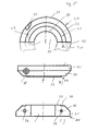
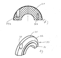
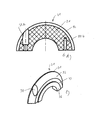
- the adaptation disks 20 are in particular in Figures 5 and 6 shown in more detail.
- the adaptation disks 20 consist of half disks 21, which form a parting line 22 between them and are fastened to one another by means of a screw connection 23.
- the screw elements 24 of the screw 23 extend in the disk plane.
- the adapter discs 20 and the half discs 21 have the following Shape features on:
- the half-discs 21 are formed as it were crescent-shaped and have at its outer edge 30 on a substantially cylindrical portion 31, which merges into an inclined surface 32 which faces the outside 33.
- the inclined surface 32 includes in the illustrated embodiment, an angle of 45 ° with the disk plane.
- the adapter disk parts 21 are provided with receiving bores 34 in order to receive the connecting elements.
- the receiving holes 34 - unless they represent blind holes - open in the at least partially in the inclined surface 32, partially in the cylindrical portion 31.
- a receiving bore 34a, a through hole and a receiving bore 34 is designed as a blind hole 34b.
- a circumferential annular collar 36 is arranged on the outer side 33 of the assembled adaptation disks 20 on the outer side 33 of the assembled adaptation disks.
- two adaptation disks 20 are mounted opposite one another on the winding shaft 7, the assembly can be a rotationally fixed mounting on the winding shaft 7, provided that the dimensions of the winding shaft diameter and the recess 35 in the half disks 21 as a result of a mutual suit of the screw 23 allow this.
Landscapes
- Engineering & Computer Science (AREA)
- Transportation (AREA)
- Mechanical Engineering (AREA)
- Storage Of Web-Like Or Filamentary Materials (AREA)
- Clamps And Clips (AREA)
- Automotive Seat Belt Assembly (AREA)
- Operating, Guiding And Securing Of Roll- Type Closing Members (AREA)
Abstract
Description
- Die Erfindung betrifft eine Spannratsche zum Aufwickeln und Spannen eines Spanngurtes, insbesondere zur Ladungsverzurrung und dergleichen oder einer bandartigen Slackline, die als Sportgerät eingesetzt werden kann. Derartige bandartige Elemente müssen, um ihre Funktion z.B. zur Ladungsverzurrung oder zum Ausüben einer Balanceübung straff zwischen zwei Fixpunkten gespannt werden, wozu in der Regel Spannratschen verwendet werden. Spannratschen weisen zwischen zwei Seitenteilen eine Wickelwelle auf, die durch einen Hebel mit Handkraft über ein Freilaufgesperre verdreht werden kann, wobei die Drehbewegung der Wickelwelle gegen die Aufwickelrichtung des Gurtes durch ein Federrastgesperre blockiert ist.
- Es ist bereits bekannt geworden, auf die Wickelwelle einer Spannratsche beidseitig so genannte Adaptionsscheiben oder Spacer aufzusetzen, um die Wickelbreite einer Wickelwelle an unterschiedlich breite Gurte anzupassen, die auf der Wickelwelle aufgerollt werden sollen. Gängig sind z.B. Gurte mit einer Breite von 25, 35 und 50 mm. Es ist so gut wie nicht möglich, einen Gurt mit einer geringeren Breite sauber auf einer Wickelwelle größerer Breite aufzurollen, ohne dass es infolge eines Abrutschens einer Gurtwicklung von bereits aufgewickelten Gurtbereichen zu seitlichen Verklemmungen des Gurtes auf der Wickelwelle kommt. Dies hat zur Folge, dass der aufgewickelte Gurt die Wickelwelle verklemmt und sowohl ein weiteres Aufwickeln infolge der Spannratschenbetätigung als auch ein Abwickeln des bereits aufgewickelten Gurtes mit großen Schwierigkeiten verbunden ist. Meist erleidet das Gurtband einen Schaden.
- Herkömmliche Spacer oder Adaptionsscheiben können in der Regel nur auf der Wickelwelle einer zerlegten Spannratsche montiert werden.
- Der Erfindung liegt die Aufgabe zugrunde, eine Spannratsche derart weiterzubilden, dass sie ohne großen Montageaufwand für unterschiedliche Gurtbreiten einsetzbar ist.
- Weiterhin betrifft die Erfindung eine mehrteilige Adaptionsscheibe zur Verwendung in einer Spannratsche, wobei die Aufgabenstellung diesbezüglich darin besteht, den Montageaufwand der Adaptionsscheibe auf einer Wickelwelle zu reduzieren.
- Diese Aufgabe wird durch die kennzeichnenden Merkmale des Anspruches 1 ebenso wie durch die Merkmalskombination des Anspruches 20 gelöst, vorteilhafte Weiterbildungen der Erfindung hinsichtlich der Spannratsche finden sich in den Unteransprüchen 2 - 19.
- Als Kern der Erfindung wird es insbesondere angesehen, die Adaptionsscheiben mehrteilig auszubilden und im Bereich wenigstens einer Trennfuge mit wenigstens einem in wenigstens eines der aneinander angelegten Adaptionsscheibenteile eingreifenden Verbindungselement versehen sind.
- Die Erfindung geht dabei von einer wenigstens zweiteiligen Adaptionsscheibe aus, die in Form zweier Halbscheiben ausgebildet sind. Die beiden Trennfugen durchsetzen dabei die Adaptionsscheibenteile mittig. Es sind aber auch mehrteilige, d.h. drei- oder vierteilige Adaptionsscheiben möglich, wobei allerdings davon auszugehen ist, dass diese schwieriger zu montieren sind. Zusammengehalten werden die jeweiligen Adaptionsscheibenteile durch das Verbindungselement, das z.B. eine Verschraubung sein kann, wobei die Schraubenelemente der Verschraubung in der Scheibenebene verlaufen. Es ist aber auch möglich, die Verbindungselemente z.B. als Nut- und Federelemente auszubilden, d.h. an einer Seite der Trennfuge ist ein Nutelement angeordnet, in das ein Federelement der anderen Hälfte eingreift. Ebenso sind Keilverbindungen oder Formstifte möglich. Sind die Verbindungselemente so ausgebildet, dass sie keinen gegenseitigen Anzug der Adaptionsscheibenteile ermöglichen, wie das beispielsweise durch eine Verschraubung möglich ist, dann kann eine Federklammer vorgesehen werden, die die Adaptionsscheibenteile, die durch die Verbindungselemente dann bereits vorfixiert sind, in Endposition hält. Die Federklammer kann einen im Wesentlichen zylindrischen Abschnitt an der Peripherie der Adaptionsscheiben angeordnet sein und in einer umlaufenden Sicke einliegen.
- Auf ihrer dem Gurt in Endmontagestellung abgewandten Außenseite sind die Adaptionsscheiben oder Adaptionsscheibenteile mit einer Schrägfläche versehen, die einen Winkel von 30 - 70° mit der Scheibenebene einschließt. Die Schrägfläche geht in den im Wesentlichen zylindrischen Abschnitt an der Peripherie der Adaptionsscheiben über bzw. grenzt an diesen zylindrischen Abschnitt an. Um stift- oder schraubenartige Verbindungselemente aufzunehmen, sind in den Adaptionsscheibenteilen Aufnahmebohrungen vorgesehen, die zumindest teilweise in der vorstehend definierten Schrägfläche münden. Eine Aufnahmebohrung ist als Sacklochbohrung und eine Aufnahmebohrung als Durchgangsbohrung ausgebildet, falls das Verbindungselement eine Schraube ist. Falls das Verbindungselement lediglich ein bolzenartiges Element ist, können beide Aufnahmebohrungen als Sacklochbohrungen ausgebildet sein.
- An der Außenseite der Adaptionsscheiben oder Adaptionsscheibenteile ist ferner ein umlaufender Ringbund angeordnet, der als Abstands-Anlageelement zur Seitenflanke der Spannratsche dient.
- Die Adaptionsscheiben können auf der Wickelwelle drehfest fixiert sein, was dadurch geschieht, dass sie entweder mit einer Nase in eine Ausnehmung der Wickelwelle eingreifen können oder auf der Peripherie der Wickelwelle durch gegenseitige Verschraubung fest verspannt sind.
- Die Erfindung ist anhand von Ausführungsbeispielen in den Zeichnungsfiguren näher erläutert. Diese zeigen
-
Fig. 1 eine perspektivische Ansicht einer Spannratsche ohne aufgesetzte Adaptionsscheiben; -
Fig. 2 eine Ansicht gemäßFig. 1 mit zwei noch im getrennten Zustand befindlichen Adaptionsscheibenteilen; -
Fig. 3 eine Ansicht gemäßFig. 2 , wobei eine Adaptionsscheibe bereits aufgesetzt ist; -
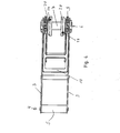
Fig. 4 eine Draufsicht auf eine Spannratsche mit aufgesetzten Adaptionsscheiben; -
Fig. 5 Ansichten einer Adaptionsscheibenhälfte einer ersten Stärke, nämlich- a. Seitenansicht,
- b. Draufsicht,
- c. Querschnitt,
- d. Schnitt in Scheibenebene,
- e. perspektivisch;
-
Fig. 6 Ansichten einer Adaptionsscheibenhälfte, nämlich- a. Seitenansicht,
- b. Draufsicht,
- c. Querschnitt,
- d. Schnitt in Scheibenebene,
- e. perspektivisch.
- Die Spannratsche 1 zum Aufwickeln und Spannen eines lediglich angedeuteten Spanngurtes 2 besteht im Wesentlichen aus zwei Seitenteilen 3, an deren freien Ende 4 eine Handhabe 5 angeordnet ist. An dem der Handhabe 5 gegenüberliegenden Ende 6 ist eine Wickelwelle 7 angeordnet, auf die der Gurt 2 durch Bewegen der Handhabe 5 in Pfeilrichtung 8 aufgerollt werden kann. Im Bereich der Wickelwelle 7 ist ein Gesperre 9 angeordnet, das die Wickelwelle 7 bei Bewegung der Handhabe 5 in Pfeilrichtung 8 mitnimmt und das als Federrastgesperre wirkt, um eine Freigabe und Rückverdrehung der Wickelwelle 7 in Abwickelrichtung zu vermeiden, es sei denn, ein Sperrhebel 10 wird aus der Verzahnung des Federrastgesperres neu ausgehoben.
- Weiterhin ist in
Figur 1 eine Hälfte einer zweiteiligen Adaptionsscheibe 20 dargestellt, die mittels einer Verschraubung 23 mit einer weiteren Hälfte einer Adaptionsscheibe 20 auf die Wickelwelle 7 aufgebracht werden kann, wie dies aus denFiguren 2 ,3 und4 ersichtlich ist. - Die Adaptionsscheiben 20 sind insbesondere in
Figuren 5 und6 näher dargestellt. Die Adaptionsscheiben 20 bestehen aus Halbscheiben 21, die zwischen sich eine Trennfuge 22 bilden und mittels einer Verschraubung 23 aneinander befestigt sind. Die Schraubenelemente 24 der Verschraubung 23 verlaufen in Scheibenebene. - Anstelle der Schraubenelemente 24 können auch andere Verbindungselemente, z.B. Nut- und Federelemente, Keilverbindungselemente oder Formstifte vorgesehen werden, um eine Vorfixierung der Halbscheiben 21 zu gewährleisten.
- Die Adaptionsscheiben 20 bzw. die Halbscheiben 21 weisen folgende Formmerkmale auf:
- Beim dargestellten Ausführungsbeispiel sind die Halbscheiben 21 gleichsam halbmondförmig ausgebildet und weisen an ihrem äußeren Rand 30 einen im Wesentlichen zylindrischen Abschnitt 31 auf, der in eine Schrägfläche 32 übergeht, die der Außenseite 33 zugewandt ist. Die Schrägfläche 32 schließt beim dargestellten Ausführungsbeispiel einen Winkel von 45° mit der Scheibenebene ein. Die Adaptionsscheibenteile 21 (Halbscheiben) sind mit Aufnahmebohrungen 34 versehen, um die Verbindungselemente aufzunehmen. Die Aufnahmebohrungen 34 - soweit sie keine Sacklochbohrungen darstellen - münden in der zumindest bereichsweise in der Schrägfläche 32, bereichsweise in dem zylindrischen Abschnitt 31. In den
Figuren 5d und6d ist dargestellt, dass eine Aufnahmebohrung 34a eine Durchgangsbohrung und eine Aufnahmebohrung 34 als Sacklochbohrung 34b ausgeführt ist. - An der Außenseite 33 der zusammengefügten Adaptionsscheiben 20 ist ein umlaufender Ringbund 36 angeordnet.
- Bei dem in
Figur 4 gezeigten Ausführungsbeispiel sind zwei Adaptionsscheiben 20 gegenüberliegend auf der Wickelwelle 7 montiert, die Montage kann eine drehfeste Montage auf der Wickelwelle 7 sein, sofern die Dimensionierungen des Wickelwellendurchmessers und die Ausnehmung 35 in den Halbscheiben 21 infolge eines gegenseitigen Anzugs der Verschraubung 23 dies zulassen.
Claims (15)
- Spannratsche (1) zum Aufwickeln und Spannen eines Spanngurtes (2) zur Ladungsverzurrung oder einer bandartigen Slackline, wobei die Spannratsche (1) zur Anpassung an einen Gurt (2) mit einer Breite, die geringer ist als die Breite der Wickelwelle (7), und mit Adaptionsscheiben (20) versehen ist,
dadurch gekennzeichnet, dass
die Adaptionsscheiben (20) mehrteilig ausgebildet sind und im Bereich wenigstens einer Trennfuge (22) mit wenigstens einem in wenigstens eines der aneinander angelegten Adaptionsscheibenteile (21) eingreifenden Verbindungselement versehen sind. - Spannratsche nach Anspruch 1,
dadurch gekennzeichnet, dass
die Adaptionsscheiben (20) zweiteilig in Form zweier Halbscheiben (21) ausgebildet sind und die beiden Trennfugen (22) die Adaptionsscheiben (20) mittig durchsetzen. - Spannratsche nach Anspruch 2,
dadurch gekennzeichnet, dass
die Halbscheiben (21) durch eine Verschraubung (23) aneinander befestigt sind. - Spannratsche nach einem der vorhergehenden Ansprüche,
dadurch gekennzeichnet, dass
die Schraubenelemente (24) der Verschraubung (23) in der Scheibenebene verlaufen. - Spannratsche nach einem der vorhergehenden Ansprüche,
dadurch gekennzeichnet, dass
die Verbindungselemente als Nut- und Federelemente, und/oder als Keilverbindung, und/oder als Formstifte ausgebildet sind. - Spannratsche nach einem der vorhergehenden Ansprüche,
dadurch gekennzeichnet, dass
die über die Verbindungselemente gegenseitig vorfixierten Adaptionsscheibenteile (21) durch eine die Adaptionsscheibenteile (21) zumindest teilweise umgreifende Federklammer aneinander befestigt sind und ein im Wesentlichen zylindrischer Abschnitt (31) an der Peripherie der Adaptionsscheiben (20) eine umlaufende Sicke für die Federklemme aufweist. - Spannratsche nach einem der vorhergehenden Ansprüche,
dadurch gekennzeichnet, dass
die Adaptionsscheiben (20) auf ihrer dem Gurt (2) in Endmontagestellung abgewandten Außenseite (33) mit einer Schrägfläche (32) versehen sind, die
vorzugsweise einen Winkel von 30 - 70° mit der Scheibenebene einschließt. - Spannratsche nach Anspruch 7,
dadurch gekennzeichnet, dass
die Schrägfläche (32) in den im Wesentlichen zylindrischen Abschnitt (31) an der Peripherie der Adaptionsscheiben (20) übergeht. - Spannratsche nach einem der vorhergehenden Ansprüche,
dadurch gekennzeichnet, dass
die Adaptionsscheibenteile (21) mit Aufnahmebohrungen (34) für das wenigstens eine Verbindungselement versehen sind. - Spannratsche nach einem der vorhergehenden Ansprüche,
dadurch gekennzeichnet, dass
die Aufnahmebohrungen (34) teilweise in der Schrägfläche (32) münden. - Spannratsche nach einem der vorhergehenden Ansprüche,
dadurch gekennzeichnet, dass
wenigstens eine Aufnahmebohrung (34) in jedem Scheibenteil (21) als Sacklochbohrung ausgebildet ist. - Spannratsche nach einem der vorhergehenden Ansprüche,
dadurch gekennzeichnet, dass
jede Halbscheibe (21) eine Sacklochbohrung (34b) und eine Durchgangsbohrung (34a) aufweist. - Spannratsche nach einem der vorhergehenden Ansprüche,
dadurch gekennzeichnet, dass
an einer vom Gurt (2) in Endmontagestellung abgewandten Außenseite (33) der Adaptionsscheiben (20) ein umlaufender Ringbund (36) angeordnet ist. - Spannratsche nach einem der vorhergehenden Ansprüche,
dadurch gekennzeichnet, dass
die Adaptionsscheiben (20) auf der Wickelwelle (7) drehfest fixierbar, sind wobei die Drehfixierung der Adaptionsscheiben (20) durch gegenseitige Verspannung der Adaptionsscheibenteile (21) und einen dadurch bewirkten Klemmsitz auf der Wickelwelle (7) erfolgt. - Mehrteilige Adaptionsscheibe (20) zur Verwendung in einer Spannratsche (1) zum Aufwickeln und Spannen eines Spanngurtes (2) zur Ladungsverzurrung oder einer bandartigen Slackline, wobei die Adaptionsscheibenteile (21) auf die Wickelwelle (7) einer unzerlegten Spannratsche (1) aufgesetzt und dort in gegenseitiger Verbindung mit Klemmsitz befestigt sind.
Applications Claiming Priority (1)
| Application Number | Priority Date | Filing Date | Title |
|---|---|---|---|
| DE200920003587 DE202009003587U1 (de) | 2009-03-16 | 2009-03-16 | Spannratsche zum Aufwickeln und Spannen eines Spanngurtes |
Publications (3)
| Publication Number | Publication Date |
|---|---|
| EP2230127A2 true EP2230127A2 (de) | 2010-09-22 |
| EP2230127A3 EP2230127A3 (de) | 2012-03-14 |
| EP2230127B1 EP2230127B1 (de) | 2013-10-02 |
Family
ID=40691244
Family Applications (1)
| Application Number | Title | Priority Date | Filing Date |
|---|---|---|---|
| EP20100002058 Not-in-force EP2230127B1 (de) | 2009-03-16 | 2010-03-01 | Spannratsche zum Aufwickeln und Spannen eines Spanngurtes |
Country Status (2)
| Country | Link |
|---|---|
| EP (1) | EP2230127B1 (de) |
| DE (1) | DE202009003587U1 (de) |
Cited By (3)
| Publication number | Priority date | Publication date | Assignee | Title |
|---|---|---|---|---|
| WO2013029315A1 (zh) * | 2011-09-02 | 2013-03-07 | 浙江双友物流器械股份有限公司 | 一种绞紧器的棘轮 |
| FR3119449A1 (fr) | 2021-02-01 | 2022-08-05 | Nexter Systems | Dispositif de maintien d’un tube d’arme par rapport à une structure |
| PL73902Y1 (pl) * | 2023-11-08 | 2025-05-19 | Ningbo Yinzhou Mairuo IMP.& EXP. Co., Ltd. | Napinacz pasa wiążącego |
Family Cites Families (3)
| Publication number | Priority date | Publication date | Assignee | Title |
|---|---|---|---|---|
| DE8014360U1 (de) * | 1980-05-29 | 1980-09-18 | Josef Haamann Hebe- Und Transporttechnik, 6982 Freudenberg | Zurrwinde mit einem Zurrgurt o.dgl. zur Sicherung von Ladegut auf Lastfahrzeugen |
| GB8826647D0 (en) * | 1988-11-15 | 1988-12-21 | Cargo Aids Ltd | Improvements in/relating to buckles/securing straps |
| DE9014602U1 (de) * | 1990-10-22 | 1991-01-03 | Krauß, Hans, 7520 Bruchsal | Vorrichtung zum Aufwickeln von auf der Ladepritsche von Lastkraftwagen verspannbaren Gurten |
-
2009
- 2009-03-16 DE DE200920003587 patent/DE202009003587U1/de not_active Expired - Lifetime
-
2010
- 2010-03-01 EP EP20100002058 patent/EP2230127B1/de not_active Not-in-force
Non-Patent Citations (1)
| Title |
|---|
| None |
Cited By (3)
| Publication number | Priority date | Publication date | Assignee | Title |
|---|---|---|---|---|
| WO2013029315A1 (zh) * | 2011-09-02 | 2013-03-07 | 浙江双友物流器械股份有限公司 | 一种绞紧器的棘轮 |
| FR3119449A1 (fr) | 2021-02-01 | 2022-08-05 | Nexter Systems | Dispositif de maintien d’un tube d’arme par rapport à une structure |
| PL73902Y1 (pl) * | 2023-11-08 | 2025-05-19 | Ningbo Yinzhou Mairuo IMP.& EXP. Co., Ltd. | Napinacz pasa wiążącego |
Also Published As
| Publication number | Publication date |
|---|---|
| EP2230127B1 (de) | 2013-10-02 |
| DE202009003587U1 (de) | 2009-05-28 |
| EP2230127A3 (de) | 2012-03-14 |
Similar Documents
| Publication | Publication Date | Title |
|---|---|---|
| DE602004001499T2 (de) | Spannvorrichtung zur Befestigung von Gütern auf einem Lastkraftwagen | |
| DE3203750C2 (de) | Spannschloß für Gurtbänder | |
| DE102005031735B3 (de) | Spannratsche zum Spannen und Halten von Spannmitteln | |
| EP2506936B1 (de) | Vorrichtung zum befestigen und klemmen von gurtbändern | |
| WO2011135015A1 (de) | Kantenschutzelement | |
| EP0281836B1 (de) | Gurtanschlussvorrichtung | |
| EP2230127B1 (de) | Spannratsche zum Aufwickeln und Spannen eines Spanngurtes | |
| DE102005038446B4 (de) | Verbindungseinheit für lose Zugmittelenden | |
| DE102007020000B4 (de) | Gurtaufroller | |
| DE2852871A1 (de) | Von hand zu betaetigende winde, insbesondere fuer die krankenpflege | |
| EP0984873A1 (de) | Belastungsanzeiger an zugmitteln | |
| DE3990337C2 (de) | Kupplungsscheibe | |
| DE3346755C2 (de) | ||
| AT504599B1 (de) | Spannschloss für eine gleitschutzkette | |
| DE202010000251U1 (de) | Spulvorrichtung eines Gurtspanners | |
| DE1256014B (de) | Spannschelle | |
| DE29816889U1 (de) | Schelle mit zwei Flanschen | |
| DE29607275U1 (de) | Spannratsche | |
| DE102009031520A1 (de) | Verstellbare Laststütze | |
| EP1864831B1 (de) | Anschluss- und Führungselement für eine Reifenkette | |
| DE3336056C2 (de) | ||
| DE102008039169A1 (de) | Umlenkbeschlag für einen Sicherheitsgurt | |
| DE20305486U1 (de) | Vorrichtung zum Spannen von Seitenplanen eines Fahrzeugaufbaus | |
| EP3693216B1 (de) | Spannvorrichtung für bänder | |
| AT390487B (de) | Spannvorrichtung |
Legal Events
| Date | Code | Title | Description |
|---|---|---|---|
| PUAI | Public reference made under article 153(3) epc to a published international application that has entered the european phase |
Free format text: ORIGINAL CODE: 0009012 |
|
| AK | Designated contracting states |
Kind code of ref document: A2 Designated state(s): AT BE BG CH CY CZ DE DK EE ES FI FR GB GR HR HU IE IS IT LI LT LU LV MC MK MT NL NO PL PT RO SE SI SK SM TR |
|
| AX | Request for extension of the european patent |
Extension state: AL BA ME RS |
|
| PUAL | Search report despatched |
Free format text: ORIGINAL CODE: 0009013 |
|
| AK | Designated contracting states |
Kind code of ref document: A3 Designated state(s): AT BE BG CH CY CZ DE DK EE ES FI FR GB GR HR HU IE IS IT LI LT LU LV MC MK MT NL NO PL PT RO SE SI SK SM TR |
|
| AX | Request for extension of the european patent |
Extension state: AL BA ME RS |
|
| RIC1 | Information provided on ipc code assigned before grant |
Ipc: A44B 11/12 20060101ALI20120206BHEP Ipc: B60P 7/08 20060101AFI20120206BHEP |
|
| 17P | Request for examination filed |
Effective date: 20120507 |
|
| GRAP | Despatch of communication of intention to grant a patent |
Free format text: ORIGINAL CODE: EPIDOSNIGR1 |
|
| INTG | Intention to grant announced |
Effective date: 20130425 |
|
| RIC1 | Information provided on ipc code assigned before grant |
Ipc: B60P 7/08 20060101AFI20130416BHEP Ipc: A44B 11/12 20060101ALI20130416BHEP |
|
| GRAS | Grant fee paid |
Free format text: ORIGINAL CODE: EPIDOSNIGR3 |
|
| GRAA | (expected) grant |
Free format text: ORIGINAL CODE: 0009210 |
|
| AK | Designated contracting states |
Kind code of ref document: B1 Designated state(s): AT BE BG CH CY CZ DE DK EE ES FI FR GB GR HR HU IE IS IT LI LT LU LV MC MK MT NL NO PL PT RO SE SI SK SM TR |
|
| REG | Reference to a national code |
Ref country code: GB Ref legal event code: FG4D Free format text: NOT ENGLISH |
|
| REG | Reference to a national code |
Ref country code: AT Ref legal event code: REF Ref document number: 634423 Country of ref document: AT Kind code of ref document: T Effective date: 20131015 Ref country code: CH Ref legal event code: EP |
|
| REG | Reference to a national code |
Ref country code: IE Ref legal event code: FG4D Free format text: LANGUAGE OF EP DOCUMENT: GERMAN |
|
| REG | Reference to a national code |
Ref country code: DE Ref legal event code: R096 Ref document number: 502010004892 Country of ref document: DE Effective date: 20131128 |
|
| REG | Reference to a national code |
Ref country code: NL Ref legal event code: VDEP Effective date: 20131002 |
|
| PG25 | Lapsed in a contracting state [announced via postgrant information from national office to epo] |
Ref country code: SI Free format text: LAPSE BECAUSE OF FAILURE TO SUBMIT A TRANSLATION OF THE DESCRIPTION OR TO PAY THE FEE WITHIN THE PRESCRIBED TIME-LIMIT Effective date: 20131002 |
|
| REG | Reference to a national code |
Ref country code: LT Ref legal event code: MG4D |
|
| PG25 | Lapsed in a contracting state [announced via postgrant information from national office to epo] |
Ref country code: SE Free format text: LAPSE BECAUSE OF FAILURE TO SUBMIT A TRANSLATION OF THE DESCRIPTION OR TO PAY THE FEE WITHIN THE PRESCRIBED TIME-LIMIT Effective date: 20131002 Ref country code: NO Free format text: LAPSE BECAUSE OF FAILURE TO SUBMIT A TRANSLATION OF THE DESCRIPTION OR TO PAY THE FEE WITHIN THE PRESCRIBED TIME-LIMIT Effective date: 20140102 Ref country code: LT Free format text: LAPSE BECAUSE OF FAILURE TO SUBMIT A TRANSLATION OF THE DESCRIPTION OR TO PAY THE FEE WITHIN THE PRESCRIBED TIME-LIMIT Effective date: 20131002 Ref country code: NL Free format text: LAPSE BECAUSE OF FAILURE TO SUBMIT A TRANSLATION OF THE DESCRIPTION OR TO PAY THE FEE WITHIN THE PRESCRIBED TIME-LIMIT Effective date: 20131002 Ref country code: IS Free format text: LAPSE BECAUSE OF FAILURE TO SUBMIT A TRANSLATION OF THE DESCRIPTION OR TO PAY THE FEE WITHIN THE PRESCRIBED TIME-LIMIT Effective date: 20140202 Ref country code: FI Free format text: LAPSE BECAUSE OF FAILURE TO SUBMIT A TRANSLATION OF THE DESCRIPTION OR TO PAY THE FEE WITHIN THE PRESCRIBED TIME-LIMIT Effective date: 20131002 Ref country code: CZ Free format text: LAPSE BECAUSE OF FAILURE TO SUBMIT A TRANSLATION OF THE DESCRIPTION OR TO PAY THE FEE WITHIN THE PRESCRIBED TIME-LIMIT Effective date: 20131002 Ref country code: HR Free format text: LAPSE BECAUSE OF FAILURE TO SUBMIT A TRANSLATION OF THE DESCRIPTION OR TO PAY THE FEE WITHIN THE PRESCRIBED TIME-LIMIT Effective date: 20131002 |
|
| PG25 | Lapsed in a contracting state [announced via postgrant information from national office to epo] |
Ref country code: PL Free format text: LAPSE BECAUSE OF FAILURE TO SUBMIT A TRANSLATION OF THE DESCRIPTION OR TO PAY THE FEE WITHIN THE PRESCRIBED TIME-LIMIT Effective date: 20131002 Ref country code: CY Free format text: LAPSE BECAUSE OF FAILURE TO SUBMIT A TRANSLATION OF THE DESCRIPTION OR TO PAY THE FEE WITHIN THE PRESCRIBED TIME-LIMIT Effective date: 20131002 Ref country code: ES Free format text: LAPSE BECAUSE OF FAILURE TO SUBMIT A TRANSLATION OF THE DESCRIPTION OR TO PAY THE FEE WITHIN THE PRESCRIBED TIME-LIMIT Effective date: 20131002 Ref country code: LV Free format text: LAPSE BECAUSE OF FAILURE TO SUBMIT A TRANSLATION OF THE DESCRIPTION OR TO PAY THE FEE WITHIN THE PRESCRIBED TIME-LIMIT Effective date: 20131002 |
|
| PG25 | Lapsed in a contracting state [announced via postgrant information from national office to epo] |
Ref country code: PT Free format text: LAPSE BECAUSE OF FAILURE TO SUBMIT A TRANSLATION OF THE DESCRIPTION OR TO PAY THE FEE WITHIN THE PRESCRIBED TIME-LIMIT Effective date: 20140203 |
|
| REG | Reference to a national code |
Ref country code: DE Ref legal event code: R097 Ref document number: 502010004892 Country of ref document: DE |
|
| PG25 | Lapsed in a contracting state [announced via postgrant information from national office to epo] |
Ref country code: EE Free format text: LAPSE BECAUSE OF FAILURE TO SUBMIT A TRANSLATION OF THE DESCRIPTION OR TO PAY THE FEE WITHIN THE PRESCRIBED TIME-LIMIT Effective date: 20131002 |
|
| PLBE | No opposition filed within time limit |
Free format text: ORIGINAL CODE: 0009261 |
|
| STAA | Information on the status of an ep patent application or granted ep patent |
Free format text: STATUS: NO OPPOSITION FILED WITHIN TIME LIMIT |
|
| PG25 | Lapsed in a contracting state [announced via postgrant information from national office to epo] |
Ref country code: RO Free format text: LAPSE BECAUSE OF FAILURE TO SUBMIT A TRANSLATION OF THE DESCRIPTION OR TO PAY THE FEE WITHIN THE PRESCRIBED TIME-LIMIT Effective date: 20131002 Ref country code: IT Free format text: LAPSE BECAUSE OF FAILURE TO SUBMIT A TRANSLATION OF THE DESCRIPTION OR TO PAY THE FEE WITHIN THE PRESCRIBED TIME-LIMIT Effective date: 20131002 Ref country code: SK Free format text: LAPSE BECAUSE OF FAILURE TO SUBMIT A TRANSLATION OF THE DESCRIPTION OR TO PAY THE FEE WITHIN THE PRESCRIBED TIME-LIMIT Effective date: 20131002 |
|
| 26N | No opposition filed |
Effective date: 20140703 |
|
| PG25 | Lapsed in a contracting state [announced via postgrant information from national office to epo] |
Ref country code: DK Free format text: LAPSE BECAUSE OF FAILURE TO SUBMIT A TRANSLATION OF THE DESCRIPTION OR TO PAY THE FEE WITHIN THE PRESCRIBED TIME-LIMIT Effective date: 20131002 |
|
| REG | Reference to a national code |
Ref country code: DE Ref legal event code: R097 Ref document number: 502010004892 Country of ref document: DE Effective date: 20140703 |
|
| PG25 | Lapsed in a contracting state [announced via postgrant information from national office to epo] |
Ref country code: LU Free format text: LAPSE BECAUSE OF FAILURE TO SUBMIT A TRANSLATION OF THE DESCRIPTION OR TO PAY THE FEE WITHIN THE PRESCRIBED TIME-LIMIT Effective date: 20140301 |
|
| GBPC | Gb: european patent ceased through non-payment of renewal fee |
Effective date: 20140301 |
|
| REG | Reference to a national code |
Ref country code: IE Ref legal event code: MM4A |
|
| PG25 | Lapsed in a contracting state [announced via postgrant information from national office to epo] |
Ref country code: GB Free format text: LAPSE BECAUSE OF NON-PAYMENT OF DUE FEES Effective date: 20140301 Ref country code: IE Free format text: LAPSE BECAUSE OF NON-PAYMENT OF DUE FEES Effective date: 20140301 |
|
| PG25 | Lapsed in a contracting state [announced via postgrant information from national office to epo] |
Ref country code: MT Free format text: LAPSE BECAUSE OF FAILURE TO SUBMIT A TRANSLATION OF THE DESCRIPTION OR TO PAY THE FEE WITHIN THE PRESCRIBED TIME-LIMIT Effective date: 20131002 |
|
| REG | Reference to a national code |
Ref country code: FR Ref legal event code: PLFP Year of fee payment: 7 |
|
| PG25 | Lapsed in a contracting state [announced via postgrant information from national office to epo] |
Ref country code: SM Free format text: LAPSE BECAUSE OF FAILURE TO SUBMIT A TRANSLATION OF THE DESCRIPTION OR TO PAY THE FEE WITHIN THE PRESCRIBED TIME-LIMIT Effective date: 20131002 Ref country code: NO Free format text: LAPSE BECAUSE OF FAILURE TO SUBMIT A TRANSLATION OF THE DESCRIPTION OR TO PAY THE FEE WITHIN THE PRESCRIBED TIME-LIMIT Effective date: 20140101 |
|
| PG25 | Lapsed in a contracting state [announced via postgrant information from national office to epo] |
Ref country code: MC Free format text: LAPSE BECAUSE OF FAILURE TO SUBMIT A TRANSLATION OF THE DESCRIPTION OR TO PAY THE FEE WITHIN THE PRESCRIBED TIME-LIMIT Effective date: 20131002 |
|
| PG25 | Lapsed in a contracting state [announced via postgrant information from national office to epo] |
Ref country code: BG Free format text: LAPSE BECAUSE OF FAILURE TO SUBMIT A TRANSLATION OF THE DESCRIPTION OR TO PAY THE FEE WITHIN THE PRESCRIBED TIME-LIMIT Effective date: 20131002 Ref country code: GR Free format text: LAPSE BECAUSE OF FAILURE TO SUBMIT A TRANSLATION OF THE DESCRIPTION OR TO PAY THE FEE WITHIN THE PRESCRIBED TIME-LIMIT Effective date: 20140103 |
|
| PG25 | Lapsed in a contracting state [announced via postgrant information from national office to epo] |
Ref country code: BE Free format text: LAPSE BECAUSE OF FAILURE TO SUBMIT A TRANSLATION OF THE DESCRIPTION OR TO PAY THE FEE WITHIN THE PRESCRIBED TIME-LIMIT Effective date: 20140331 Ref country code: HU Free format text: LAPSE BECAUSE OF FAILURE TO SUBMIT A TRANSLATION OF THE DESCRIPTION OR TO PAY THE FEE WITHIN THE PRESCRIBED TIME-LIMIT; INVALID AB INITIO Effective date: 20100301 Ref country code: TR Free format text: LAPSE BECAUSE OF FAILURE TO SUBMIT A TRANSLATION OF THE DESCRIPTION OR TO PAY THE FEE WITHIN THE PRESCRIBED TIME-LIMIT Effective date: 20131002 |
|
| REG | Reference to a national code |
Ref country code: FR Ref legal event code: PLFP Year of fee payment: 8 |
|
| REG | Reference to a national code |
Ref country code: FR Ref legal event code: PLFP Year of fee payment: 9 |
|
| PGFP | Annual fee paid to national office [announced via postgrant information from national office to epo] |
Ref country code: CH Payment date: 20180326 Year of fee payment: 9 |
|
| PGFP | Annual fee paid to national office [announced via postgrant information from national office to epo] |
Ref country code: AT Payment date: 20180320 Year of fee payment: 9 Ref country code: FR Payment date: 20180326 Year of fee payment: 9 |
|
| PG25 | Lapsed in a contracting state [announced via postgrant information from national office to epo] |
Ref country code: MK Free format text: LAPSE BECAUSE OF FAILURE TO SUBMIT A TRANSLATION OF THE DESCRIPTION OR TO PAY THE FEE WITHIN THE PRESCRIBED TIME-LIMIT Effective date: 20131002 |
|
| PGFP | Annual fee paid to national office [announced via postgrant information from national office to epo] |
Ref country code: DE Payment date: 20180327 Year of fee payment: 9 |
|
| REG | Reference to a national code |
Ref country code: DE Ref legal event code: R119 Ref document number: 502010004892 Country of ref document: DE |
|
| REG | Reference to a national code |
Ref country code: CH Ref legal event code: PL |
|
| REG | Reference to a national code |
Ref country code: AT Ref legal event code: MM01 Ref document number: 634423 Country of ref document: AT Kind code of ref document: T Effective date: 20190301 |
|
| PG25 | Lapsed in a contracting state [announced via postgrant information from national office to epo] |
Ref country code: AT Free format text: LAPSE BECAUSE OF NON-PAYMENT OF DUE FEES Effective date: 20190301 Ref country code: LI Free format text: LAPSE BECAUSE OF NON-PAYMENT OF DUE FEES Effective date: 20190331 Ref country code: DE Free format text: LAPSE BECAUSE OF NON-PAYMENT OF DUE FEES Effective date: 20191001 Ref country code: CH Free format text: LAPSE BECAUSE OF NON-PAYMENT OF DUE FEES Effective date: 20190331 |
|
| PG25 | Lapsed in a contracting state [announced via postgrant information from national office to epo] |
Ref country code: FR Free format text: LAPSE BECAUSE OF NON-PAYMENT OF DUE FEES Effective date: 20190331 |