EP2229582B1 - Inspektionsvorrichtung mit rotierbarer beleuchtungsumhausung - Google Patents
Inspektionsvorrichtung mit rotierbarer beleuchtungsumhausung Download PDFInfo
- Publication number
- EP2229582B1 EP2229582B1 EP08801726.4A EP08801726A EP2229582B1 EP 2229582 B1 EP2229582 B1 EP 2229582B1 EP 08801726 A EP08801726 A EP 08801726A EP 2229582 B1 EP2229582 B1 EP 2229582B1
- Authority
- EP
- European Patent Office
- Prior art keywords
- hollow body
- inspection device
- inspection
- containers
- unit
- Prior art date
- Legal status (The legal status is an assumption and is not a legal conclusion. Google has not performed a legal analysis and makes no representation as to the accuracy of the status listed.)
- Not-in-force
Links
Images


Classifications
-
- G—PHYSICS
- G01—MEASURING; TESTING
- G01N—INVESTIGATING OR ANALYSING MATERIALS BY DETERMINING THEIR CHEMICAL OR PHYSICAL PROPERTIES
- G01N21/00—Investigating or analysing materials by the use of optical means, i.e. using sub-millimetre waves, infrared, visible or ultraviolet light
- G01N21/01—Arrangements or apparatus for facilitating the optical investigation
- G01N21/15—Preventing contamination of the components of the optical system or obstruction of the light path
-
- G—PHYSICS
- G01—MEASURING; TESTING
- G01N—INVESTIGATING OR ANALYSING MATERIALS BY DETERMINING THEIR CHEMICAL OR PHYSICAL PROPERTIES
- G01N21/00—Investigating or analysing materials by the use of optical means, i.e. using sub-millimetre waves, infrared, visible or ultraviolet light
- G01N21/84—Systems specially adapted for particular applications
- G01N21/88—Investigating the presence of flaws or contamination
- G01N21/90—Investigating the presence of flaws or contamination in a container or its contents
- G01N21/9009—Non-optical constructional details affecting optical inspection, e.g. cleaning mechanisms for optical parts, vibration reduction
-
- G—PHYSICS
- G01—MEASURING; TESTING
- G01N—INVESTIGATING OR ANALYSING MATERIALS BY DETERMINING THEIR CHEMICAL OR PHYSICAL PROPERTIES
- G01N21/00—Investigating or analysing materials by the use of optical means, i.e. using sub-millimetre waves, infrared, visible or ultraviolet light
- G01N21/01—Arrangements or apparatus for facilitating the optical investigation
- G01N21/15—Preventing contamination of the components of the optical system or obstruction of the light path
- G01N2021/151—Gas blown
-
- G—PHYSICS
- G01—MEASURING; TESTING
- G01N—INVESTIGATING OR ANALYSING MATERIALS BY DETERMINING THEIR CHEMICAL OR PHYSICAL PROPERTIES
- G01N21/00—Investigating or analysing materials by the use of optical means, i.e. using sub-millimetre waves, infrared, visible or ultraviolet light
- G01N21/01—Arrangements or apparatus for facilitating the optical investigation
- G01N21/15—Preventing contamination of the components of the optical system or obstruction of the light path
- G01N2021/152—Scraping; Brushing; Moving band
-
- G—PHYSICS
- G01—MEASURING; TESTING
- G01N—INVESTIGATING OR ANALYSING MATERIALS BY DETERMINING THEIR CHEMICAL OR PHYSICAL PROPERTIES
- G01N21/00—Investigating or analysing materials by the use of optical means, i.e. using sub-millimetre waves, infrared, visible or ultraviolet light
- G01N21/17—Systems in which incident light is modified in accordance with the properties of the material investigated
- G01N21/21—Polarisation-affecting properties
-
- G—PHYSICS
- G01—MEASURING; TESTING
- G01N—INVESTIGATING OR ANALYSING MATERIALS BY DETERMINING THEIR CHEMICAL OR PHYSICAL PROPERTIES
- G01N2201/00—Features of devices classified in G01N21/00
- G01N2201/06—Illumination; Optics
- G01N2201/063—Illuminating optical parts
- G01N2201/0634—Diffuse illumination
Definitions
- the invention relates to an inspection device for controlling containers, in particular bottles, with the features of the preamble of patent claim 1, i. an inspection device comprising at least one transport path for supplying and discharging the container, a lighting unit, an optical measuring unit and a control unit, wherein the lighting unit is surrounded by a rotatably mounted around the central axis and transparent hollow body and the hollow body directly or via suitable operative connections motor is drivable.
- the hollow body is a tube made of a material or mixture of materials which is transparent to radiations of optical-visible, infrared and / or ultra-violet wavelengths, the material being at least partially permeable to these radiations.
- EP 0 894 544 A as well as the DE 196 05 133 A1 disclose an inspection machine, in which the containers, here bottles, are conveyed hanging over a lighting unit.
- the lighting unit itself is a cuboid block, which transilluminates the containers from below.
- these devices are proven and suitable, need only be cleaned relatively often to ensure safe operation and meaningful readings.
- a device for scanning eggs with infrared light beam bundles which are each directed from below to the eggs to be inspected, as well as with a camera system for detecting the images obtained by transillumination ( FR 2 768 517 A ).
- the diodes emitting the infrared light are arranged in a tubular, transparent hollow body, which in turn is partially accommodated in a cleaning bath and is moved for cleaning its outer surface by rotation through the cleaning bath.
- the object of the invention is to provide an inspection device available in which the cleaning effort is reduced.
- an inspection device according to claim 1 is formed.
- a method for inspecting containers is the subject of claim 13.
- Core of the inspection device is the lighting unit, which is enclosed by a rotatably mounted around the central axis and transparent hollow body, wherein the hollow body is directly driven by motor or driven by suitable active compounds. Dirt, label rights, dust and moisture can thus be removed from the surveillance area without interrupting the actual measurement or monitoring.
- the axis of rotation of the hollow body may in principle have any orientation. Ideally, the axis of rotation of the hollow body is aligned parallel or transversely to the conveying direction of the container.
- the hollow body is a tube which is made of a material or a material mixture which is at least partially permeable to radiations of wavelengths in the optically visible range, in the infrared range and / or in the UV range for such radiations.
- a material or a material mixture which is at least partially permeable to radiations of wavelengths in the optically visible range, in the infrared range and / or in the UV range for such radiations.
- suitable PTFE acrylic glass or tempered glass can be used.
- An improvement of the inspection device is that between the hollow body and the top of the lighting unit, a diffusion element is arranged, which leads to a homogenization of the illumination means.
- the upper side of the lighting unit is to be understood as that side which faces the inspecting container or the bottle to be inspected and via which the radiation takes place.
- the underside is the corresponding counterpart.
- the diffusion element may basically have a flat, planar shape, but it has been found that it is advantageously curved and arranged between the hollow body and the upper side of the lighting element, wherein the materials and the manufacturing processes for such diffusion elements are basically known.
- a further improvement of the inspection device can be achieved if a polarizing filter is provided, which is ideally arranged between the hollow body and the upper side of the lighting unit and advantageously also has a curved shape.
- polarizing filters or circular polarizing filters for inspection machines is known and used, for example, to achieve reliable detection of transparent solids, such as foils, in the container.
- Suitable polarizing filters consist for example of a film of polyvinyl alcohol, which can be mechanically stabilized by means of coating on both sides of a Celluloseacetaobutyrat.
- Other materials are basically known and can be used depending on the application.
- a cleaning unit which ideally is arranged below the illumination unit, is arranged on the hollow body on the inspection device.
- This cleaning unit may further comprise a feeding device.
- the feeding device has outlets or nozzles for illuminating the outer surface of the hollow body and is suitable for gaseous or liquid media.
- the cleaning unit comprises at least one removal device which has mechanical wipers in the form of brushes, sealing lips made of a flexible material or suction elements in order to remove solid or liquid adhesions from the surface of the hollow body.
- the adhesions are conveyed permanently or sequentially from the upper side, that is, out of the inspection field, to the lower side. There, without having to take the measuring and inspection process into account, any suitable and required wet and / or dry cleaning can take place.
- the rotating hollow body of the inspection device may be open on at least one side for reasons of heat generation and for the power supply. In this way, deposits can reach the inner surface and be conveyed into the inspection field.
- An improvement therefore consists in that the cleaning unit projects onto or into the hollow body in such a way that at least solid or liquid adhesions can be removed from the outer surface of the hollow body and, ideally, can also be removed from the inner surface.
- a cantilever arm which has suitable wipers protrude into the interior and there do cleaning work.
- the hollow body is closed and connected to a gas line, through which an inert gas, in particular compressed air can be passed into the interior of the hollow body during normal operation.
- an inert gas in particular compressed air
- the invention further comprises a method for inspecting containers, in particular bottles, in which an inspection device according to one of the preceding embodiments is used.
- An improvement of the inspection method is that the surface of the hollow body permanently or intermittently cleaned or permanently a gas, ideally purified compressed air, is passed into the hollow body.
- a pressure is maintained, which is greater than the ambient pressure and ideally exceeds the ambient pressure by 0.2 to 0.5 bar.
- the gas or the compressed air which can be referred to as purge gas, has a dual function, namely to keep the interior of soiling free and to cool the interior. Therefore, it may be advantageous that in the conduction path of the gas supply line, a cooling device is arranged, via which at least temporarily the gas can be cooled. Furthermore, it may be advantageous to dry the purge gas prior to introduction into the hollow body.
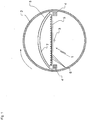
- Fig. 1 shows the inspection device in a sectional view of the lighting unit 1.
- the hollow body 2 is a transparent tube made of a UV-transparent acrylic glass and has in the example shown on a diameter of 130 mm.
- the hollow body 2 is rotatably mounted about an axis of rotation 3 emerging from the plane of the drawing.
- the selected here two-fold storage at belden ends of the hollow body 2 and the drive at one of the pipe ends are not shown.
- the cuboid lighting unit 1 which rests on two support arms 4.
- the lighting unit 1 comprises a planar, horizontal support 5, on which a diode array is arranged, which comprises a plurality of diodes 6, which are connected in a manner not shown electrically connected to a voltage source. Above the lighting unit 1, two arcuate elements are arranged. The lower arc is the diffusion element 7. The largest distance between the diodes 6 and the diffusion element 7, the dome height, is 40 mm. At a short distance, the diffusion element 7 is spanned by a polarization element or polarization filter 8, which in the illustrated example comprises a linear polarization film.
- the designations are, even if not always explicitly mentioned below, identical in their meaning in all figures.
- Fig. 2 shows the device in a plan view.
- the bottle 9 is located on a conveyor belt 10, which conveys the bottle 9 in the direction of the arrow towards the lighting unit 1.
- the bottle 9 is already in the effective range of the vertical lifting straps 11 and 12 and directly before or already partially above the gap 14 formed between the conveying conveyor belt 10 and the conveying conveyor belt 15.
- Under this gap 14 are the lighting unit, not shown, and this surrounding the lighting unit 1 and rotating about the rotation axis 3 hollow body. 2
- the endlessly circulating lifting straps are driven at different speeds, so that the bottle 9 located in the effective region of the lifting straps 11 and 12 rotates about its central axis,
- the Fig. 3 shows the same device or the same method in a side view.
- the lighting unit 1 In the gap 14, between the conveyor belts 10 and 15, the lighting unit 1 with the rotating, transparent hollow body 2.
- the lighting unit 1 is spanned by the polarization element 8 and the diffusion element 7.
- two cameras 16 Above the gap 14, two cameras 16 are placed, which Record signals and forward to an evaluation and control unit 17.
- a cleaning unit 18 is arranged below the hollow body 2, in the region of the gap 14. This consists of a spray head 19, a pump 20, a storage container 21, a collecting trough 22, a motor-pivotable wiper 23 and a drying unit.
- the outer surface of the hollow body 2 is sprayed by the pump 20 via the spray head 19 sequentially.
- the scraper 23 is driven by the motor 28, brought to the surface of the hollow body 2.
- the scraper 23 has double wiper lips, comparable to a wiper blade for car windows, and consists of a silicone material. Due to this arrangement, part of the adherence flows from the deepest pipe section into the sump 22. Residual buildup and moisture are removed by the wiper 23 and also fall into the sump 22. The cleaning fluid is directed into the receiver 21 via a pipeline is available for reuse.
- a drying unit which comprises a hot air blower 24, which accomplishes the final drying of the cleaned outer surface of the hollow body 2.
- the associated with the Schubuchgebläse 24 compressor 25 and the associated heating unit 26 are also controlled by the evaluation and control unit 17.
- the surface of the protective hollow body 2 can thus be optimally cleaned. Constantly dragging elements or scrapers, which themselves lead to contamination, are avoided.
- the surface of the hollow body 2 is monitored in the direction of rotation after the scraper 23 and the Schuzzigebläse 24 via the camera 27. This corresponds to a monitoring of the cleaning performance of the cleaning unit 18. Error messages or deviations from the desired value are also passed to the evaluation and control unit 17 and processed there.
Landscapes
- Physics & Mathematics (AREA)
- Health & Medical Sciences (AREA)
- Life Sciences & Earth Sciences (AREA)
- Chemical & Material Sciences (AREA)
- Analytical Chemistry (AREA)
- Biochemistry (AREA)
- General Health & Medical Sciences (AREA)
- General Physics & Mathematics (AREA)
- Immunology (AREA)
- Pathology (AREA)
- Investigating Materials By The Use Of Optical Means Adapted For Particular Applications (AREA)
- Cleaning In General (AREA)
Description
- Die Erfindung betrifft eine Inspektionsvorrichtung zum Kontrollieren von Behältern, insbesondere Flaschen, mit den Merkmalen des Oberbegriffs des Patentanspruchs 1, d.h. eine Inspektionsvorrichtung, die mindestens eine Transportstrecke zum Zu- und Abfördern der Behälter, eine Beleuchtungseinheit, eine optische Messeinheit und eine Steuereinheit umfasst, wobei die Beleuchtungseinheit von einem um die Mittelachse rotierend gelagerten und transparenten Hohlkörper umschlossen wird und der Hohlkörper direkt oder über geeignete Wirkverbindungen motorisch antreibbar ist. Idealerweise ist der Hohlkörper ein Rohr, das aus einem Material oder einer Materialmischung hergestellt ist, welches für Strahlungen von Wellenlängen im optisch-sichtbaren Bereich, im Infrarotbereich und/oder im ultravioletten Bereich durchlässig ist, wobei das Material für diese Strahlungen mindestens teilweise durchlässig ist.
- Aus dem Stand der Technik sind Vorrichtungen zur Beleuchtung und Inspektion von Behälterböden bekannt und hinreichend beschrieben.
EP 0 894 544 A sowie dieDE 196 05 133 A1 offenbaren eine Inspektionsmaschine, bei der die Behälter, hier Flaschen, über eine Beleuchtungseinheit hängend gefördert werden. Die Beleuchtungseinheit selbst ist ein quaderförmiger Block, der die Behälter von unten durchleuchtet. Im Prinzip sind diese Vorrichtungen bewährt und geeignet, müssen lediglich relativ häufig gereinigt werden um einen sicheren Betrieb und aussagekräftige Messwerte zu gewährleisten. - In der
DE 10 2005 057 872 A1 wird vorgeschlagen, den von unten angestrahlten Transporteur, auf dem die zu inspizierenden Flaschen stehen, transparent und als Drehscheibe auszuformen. Hier wird die Verunreinigung auf der Beleuchtungseinheit selbst verringert, aber fest und flüssige Anhaftungen auf der transparenten Drehscheibe selbst, erfordern ebenfalls eine regelmäßige Reinigung. - Bekannt ist (
DE 101 47 617 A1 ), bei einer Vorrichtung zum Aufschneiden von Lebensmittelprodukte, insbesondere zum Aufschneiden von Wurst oder Schinken unterhalb der Schneidkante eines Schneidwerkzeugs eine Beleuchtungseinrichtung anzuordnen, mit der ein Ausleuchten der Schnittseite des Lebensmittelproduktes durch Auflicht möglich Ist. Zur Vermeidung einer Verschmutzung der Beleuchtungseinheit ist diese in einem transparenten rohrförmigen Hohlkörper untergebracht, der für eine Außenreinigung rotierend an eine Reinigungseinheit vorbei bewegbar ist. - Bekannt Ist weiterhin eine Vorrichtung zum Durchleuchten von Eiern mit Infrarot-Lichtstrahlbündeln, die jeweils von unten her auf die zu inspizierenden Eier gerichtet sind, sowie mit einem Kamerasystem zum Erfassen der beim Durchleuchten erhaltenen Bilder (
FR 2 768 517 A - Aufgabe der Erfindung ist es, eine Inspektionsvorrichtung zur Verfügung zu stellen, bei der der Reinigungsaufwand vermindert ist.
- Zur Lösung dieser Aufgabe Ist eine Inspektionsvorrichtung entsprechend dem Patentanspruch 1 ausgebildet. Ein Verfahren zur Inspektion von Behältern ist Gegenstand des Patentanspruchs 13.
- Kern der Inspektionsvorrichtung ist dabei die Beleuchtungseinheit, welche von einem um die Mittelachse rotierend gelagerten und transparenten Hohlkörper umschlossen wird, wobei der Hohlkörper direkt oder über geeignete Wirkverbindungen motorisch antreibbar ist. Schmutz, Etikettenrechte, Staub und Feuchtigkeit kann auf diese Wiese, ohne die eigentliche Messung oder Überwachung zu unterbrechen, aus dem Überwachungsbereich entfernt werden. Die Rotationsachse des Hohlkörpers kann prinzipiell eine beliebige Ausrichtung aufweisen. Idealerweise ist die Rotationsachse des Hohlkörpers parallel oder quer zur Förderrichtung der Behälter ausgerichtet.
- Idealerweise ist der Hohlkörper ein Rohr, das aus einem Material oder einer Materialmischung hergestellt ist, welches für Strahlungen von Wellenlängen Im optisch-sichtbaren Bereich, im Infrarotbereich und/oder im UV-Bereich für derartige Strahlungen mindestens teilweise durchlässig ist. Hierzu sind prinzipiell bekannte Materialien aus geeignetem PTFE, Acrylglas oder getempertem Glas einsetzbar.
- Eine Verbesserung der Inspektionsvorrichtung besteht darin, dass zwischen dem Hohlkörper und der Oberseite der Beleuchtungseinheit ein Diffusionselement angeordnet ist, welches zu einer Vergleichmäßigung der Beleuchtungsmittel führt. Dabei soll unter Oberseite der Beleuchtungseinheit diejenige Seite verstanden werden, die zu dem inspizierenden Behälter oder der zu inspizierenden Flasche weist und über welche die Abstrahlung erfolgt. Als Unterseite wird das entsprechende Gegenstück bezeichnet.
- Das Diffusionselement kann grundsätzlich eine flache, ebene Form haben, es hat sich aber herausgestellt, dass sie vorteilhafterweise gewölbt und zwischen Hohlkörper und der Oberseite des Beleuchtungselementes angeordnet Ist, wobei die Materialien und die Herstellungsprozesse für derartige Diffusionselemente grundsätzlich bekannt sind.
- Eine weitere Verbesserung der Inspektionsvorrichtung kann erreicht werden, wenn ein Polarisationsfilter vorgesehen wird, der idealerweise zwischen dem Hohlkörper und der Oberseite der Beleuchtungseinheit angeordnet wird und vorteilhafterweise ebenfalls eine gewölbte Form aufweist. Der Einsatz von Polarisationsfiltern oder zirkularen Polarisationsfiltern für Inspektionsmaschinen ist bekannt und wird zum Beispiel genutzt, um eine sichere Erkennung von transparenten Feststoffen, wie bspw. Folien, im Behälter zu erreichen.
- Geeignete Polarisationsfilter bestehen beispielsweise aus einer Folie aus Polyvinylalkohol, welche mittels beidseitigem Überzug aus einem Celluloseacetaobutyrat mechanisch stabilisiert werden kann. Weitere Materialien sind grundsätzlich bekannt und vom Einsatzfall abhängig einsetzbar.
- An der Inspektionsvorrichtung ist bei einer Variante der Vorrichtung an dem Hohlkörper eine Reinigungseinheit angeordnet ist, die idealerweise unterhalb der Beleuchtungseinheit angeordnet. Diese Reinigungseinheit kann weiterhin eine Aufgabevorrichtung umfassen. Die Aufgabevorrichtung weist Auslässe oder Düsen zum Anstrahlen der äußeren Oberfläche des Hohlkörpers auf und ist für gasförmige oder flüssige Medien geeignet ist.
- In einer verbesserten Variante umfasst die Reinigungseinheit mindestens eine Abnahmevorrichtung, die mechanische Abstreifer in Form von Bürsten, Dichtlippen aus einem flexiblen Material oder Absaugelemente aufweist, um feste oder flüssige Anhaftungen von der Oberfläche des Hohlkörpers zu entfernen. Durch die Rotation des Hohlkörpers werden die Anhaftungen permanent oder sequentiell von der Oberseite, also aus dem Inspektionsfeld, zur Unterseite gefördert. Dort kann, ohne Rücksicht auf den Mess- und Inspektionsvorgang nehmen zu müssen jede geeignete und erforderliche nasse und/oder trockene Reinigung erfolgen.
- Der rotierende Hohlkörper der Inspektionsvorrichtung kann aus Gründen der Hitzeentwicklung und für die Stromversorgung an mindestens einer Seite offen sein. Auf diesem Wege können Ablagerungen an die innere Oberfläche gelangen und in das Inspektionsfeld gefördert werden. Ein Verbesserung besteht daher darin, dass die Reinigungseinheit derart an oder in den Hohlkörper ragt, dass mindestens feste oder flüssige Anhaftungen von der äußeren Oberfläche des Hohlkörpers entfernt werden können und idealerweise auch von der inneren Oberfläche entfernbar sind. Bei einem zylindrischen Hohlkörper kann ein Kragarm, der geeignete Abstreifer aufweist in den Innenraum hineinragen und dort Reinigungsarbeiten erledigen.
- Bei der erfinderischen Inspektionsvorrichtung ist der Hohlkörper geschlossen und mit einer Gasleitung verbunden, über welche im bestimmungsgemäßen Betrieb ein inertes Gas, insbesondere Druckluft in das Innere des Hohlkörpers geleitet werden kann. Durch die Aufrechterhaltung eines permanenten Überdruckes im Innenraum das Hohlkörpers, kann eine Verschmutzung der inneren Oberflächen sicher vermieden werden.
- Von der Erfindung ist weiterhin ein Verfahren zur Inspektion von Behältern, insbesondere Flaschen umfasst, bei welchem eine Inspektionsvorrichtung gemäß einem der vorstehenden Ausführungsformen eingesetzt wird.
- Die wesentlichen Verfahrensschritte sind:
- a) Permanente oder gelegentliche Rotation des Hohlkörpers
- b) Antransport der Behälter
- c) Schwebender Transport im Bereich der Inspektionseinheit
- d) Inspektion der Behälter
- e) Abtransport der Behälter
- Eine Verbesserung der Inspektionsverfahren besteht darin, dass die Oberfläche des Hohlkörpers permanent oder intervallweise gereinigt oder permanent ein Gas, idealerweise gereinigte Druckluft, in den Hohlkörper geleitet wird. Im Inneren des Hohlkörpers wird vorteilhafterweise ein Druck aufrecht gehalten, der größer als der Umgebungsdruck ist und idealerweise den Umgebungsdruck um 0,2 bis 0,5 bar übersteigt. Das Gas oder die Druckluft, welche als Spülgas bezeichnet werden kann, hat eine doppelte Funktion, nämlich den Innenraum von Verschmutzungen frei zu halten und den Innenraum zu kühlen. Daher kann es vorteilhaft sein, dass im Leitungsweg der Gaszuleitung eine Kühlvorrichtung angeordnet ist, über die wenigstens zeitweise das Gas gekühlt werden kann. Weiterhin kann es vorteilhaft sein, das Spülgas vor dem Einleiten in die Hohlkörper zu trockenen.
- Nachfolgend sind anhand von Beispielen die Inspektionsvorrichtung und das Inspektionsverfahren erläutert.
Fig. 1 zeigt die Inspektionsvorrichtung in einer Schnittzeichnung die Beleuchtungseinheit 1. Der Hohlkörper 2 ist ein transparentes Rohr aus einem UV-durchlässigen Acrylglas und weist in dem gezeigten Beispiel einen Durchmesser von 130 mm auf. Der Hohlkörper 2 ist um eine aus der Zeichenebene heraustretenden Rotationsachse 3 rotierend gelagert. Für die Lagerung und den Antrieb stehen dem Fachmann viele bekannte Lösungsmöglichkeiten offen, die hier gewählte zweifache Lagerung an belden Enden des Hohlkörpers 2 und der Antrieb an einem der Rohrenden sind nicht dargestellt. Im Inneren des Hohlkörpers 2 befindet sich die quaderförmige Beleuchtungseinheit 1, die auf zwei Tragarmen 4 ruht. Die rückseitige Aufhängung der Tragarme 4 und der motorische Antrieb des transparenten Hohlkörpers 2 sind nicht näher skizziert, da derartige Vorrichtungen dem Fachmann bekannt sind. Die Beleuchtungseinheit 1 umfasst einen flächigen, horizontalen Träger 5, auf dem ein Diodenfeld angeordnet ist, das eine Vielzahl von Dioden 6 umfasst, die in nicht dargestellter Weise elektrisch mit einer Spannungsquelle verbunden sind. Über der Beleuchtungseinheit 1 sind zwei bogenförmige Elemente angeordnet. Der untere Bogen ist das Diffusionselement 7. Der größte Abstand zwischen den Dioden 6 und dem Diffusionselement 7, die Wölbungshöhe, beträgt 40 mm. In geringem Abstand wird das Diffusionselement 7 von einem Polarisationselement oder Polarisationsfilter 8 überspannt, das im dargestellten Beispiel eine lineare Polarisationsfolie umfasst. Die Bezeichnungen sind, auch wenn nachfolgend nicht immer ausdrücklich genannt, in ihrer Bedeutung in allen Figuren identisch. -
Fig. 2 zeigt die Vorrichtung in einer Draufsicht. Die Flasche 9 befindet sich auf einem Transportband 10, das die Flasche 9 in Pfeilrichtung hin zur Beleuchtungseinheit 1 befördert. In dem gezeigten Stadium des Verfahrens befindet sich die Flasche 9 bereits im Wirkbereich der senkrechten Hebebänder 11 und 12 und direkt vor bzw. bereits teilweise über dem Spalt 14, der zwischen dem zufördernden Transportband 10 und dem abfördernden Transportband 15 gebildet ist. Unter diesem Spalt 14 befinden sich die nicht dargestellte Beleuchtungseinheit und der diese Beleuchtungseinheit 1 umschließende und um die Rotationsachse 3 rotierende Hohlkörper 2. - In dem gezeigten Beispiel werden die endlos umlaufenden Hebebänder mit unterschiedlichen Geschwindigkeiten angetrieben, so dass die im Wirkbereich der Hebebänder 11 und 12 befindliche Flasche 9 um ihre zentrale Achse rotiert,
- Die
Fig. 3 zeigt die gleiche Vorrichtung bzw. das gleiche Verfahren in einer Seitenansicht. In dem Spalt 14, zwischen den Transportbändern 10 und 15 ist die Beleuchtungseinheit 1 mit dem rotierenden, transparenten Hohlkörper 2. Die Beleuchtungseinheit 1 wird überspannt von dem Polarisationselement 8 und dem Diffusionselement 7. Oberhalb des Spaltes 14 sind zwei Kameras 16 platziert, die die Signale aufnehmen und an eine Auswerte- und Steuereinheit 17 weiterleiten. Unterhalb des Hohlkörpers 2, im Bereich des Spaltes 14 ist eine Reinigungseinheit 18 angeordnet. Diese besteht aus eine Sprühkopf 19, einer Pumpe 20, einem Vorlagebehälter 21, einer Auffangwanne 22, einem motorisch schwenkbaren Abstreifer 23 und einer Trocknungseinheit. - Von der Auswerte- und Steuereinheit 17 angesteuert, wird durch die Pumpe 20 über den Sprühkopf 19 sequentiell die äußere Oberfläche des Hohlkörpers 2 angesprüht. Zeitlich davor oder zeitgleich wird der Abstreifer 23 vom Motor 28 angetrieben, an die Oberfläche des Hohlkörpers 2 herangeführt. Der Abstreifer 23 weist doppelte Wischlippen auf, vergleichbar einem Wischblatt für Autoscheiben, und besteht aus einem Siliconmaterial. Aufgrund dieser Anordnung fließt oder fällt ein Teil der Anhaftung vom tiefsten Rohrabschnitt in die Auffangwanne 22. Restliche Anhaftungen und Feuchtigkeit werden durch den Abstreifer 23 entfernt und fallen ebenfalls in die Auffangwanne 22. Über eine Rohrleitung wird das Reinigungsfluid in den Vorlagebehälter 21 geleitet, wo es für einen erneuten Einsatz zur Verfügung steht.
- In Rotationsrichtung nach dem Abstreifer 23 ist eine Trocknungseinheit angeordnet, die ein Warmluftgebläse 24 umfasst, welches die finale Trocknung der gereinigten äußeren Oberfläche des Hohlkörpers 2 bewerkstelligt. Der mit dem Heizluftgebläse 24 verbundene Verdichter 25 und das dazugehörige Heizaggregat 26, werden ebenfalls von der Auswerte- und Steuereinheit 17 angesteuert.
- Die Oberfläche des schützenden Hohlkörpers 2 kann somit optimal gereinigt werden. Ständig schleifende Elemente oder Abstreifer, die selbst zu Verunreinigungen führen, werden vermieden. In dem vorliegenden Beispiel wird die Oberfläche des Hohlkörpers 2 in Rotationsrichtung nach dem Abstreifer 23 und dem Heizluftgebläse 24 über die Kamera 27 überwacht. Dies entspricht einer Überwachung der Reinigungsleistung der Reinigungseinheit 18. Fehlermeldungen oder Abweichungen vom Sollwert werden ebenfalls an die Auswerte- und Steuereinheit 17 geleitet und dort verarbeitet.
Claims (15)
- Inspektionsvorrichtung zum Kontrollieren von Behältern (9), insbesondere Flaschen, umfassend mindestens eine Transportstrecke (10, 11, 12, 15) oder einen Transportstern zum Zu- und Abfördern der Behälter (9) in einer Förderrichtung, eine Beleuchtungseinheit (1), eine optische Messeinheit (16) und eine Steuereinheit (17), dadurch gekennzeichnet,
dass die Beleuchtungseinheit (1) von einem um die Mittelachse rotierend gelagerten und transparenten Hohlkörper (2) umschlossen wird,
dass der Hohlkörper (2) direkt oder über geeignete Wirkverbindungen motorisch antreibbar ist, und dass die Rotationsachse (3) des Hohlkörpers (2) insbesondere parallel oder quer zur Förderrichtung der Behälter (9) ausgerichtet ist,
dass zwischen dem Hohlkörper (2) und der Oberseite der Beleuchtungseinheit (1) ein Diffusionselement (7) und/oder ein Polarisationsfilter (8) angeordnet sind,
dass der Hohlkörper (2) mindestens teilweise geschlossen ist, und
dass mindestens eine Gasleitung zur Erzeugung eines Überdrucks durch ein eingeleitetes Gas in den Innenraum des Hohlkörpers (2) geführt ist. - Inspektionsvorrichtung nach Anspruch 1, dadurch gekennzeichnet, dass der Hohlkörper (2) ein Rohr aus einem Material oder einer Materialmischung hergestellt ist, das für Strahlungen von Wellenlängen im optisch-sichtbaren Bereich, im Infrarotbereich und/oder im ultravioletten Bereich durchlässig ist, und dass das Material für diese Strahlungen mindestens teilweise durchlässig ist.
- Inspektionsvorrichtung nach Anspruch 1 oder 2, dadurch gekennzeichnet, dass das Diffusionselement (7) gewölbt zwischen Hohlkörper (2) und der Oberseite des Beleuchtungselementes angeordnet ist.
- Inspektionsvorrichtung nach einem der vorstehenden Ansprüche, dadurch gekennzeichnet, dass das Polarisationsfilter (8) ein zirkulärer Polarisationsfilter ist.
- Inspektionsvorrichtung nach Anspruch 4, dadurch gekennzeichnet, dass der Polarisationsfilter (8) gewölbt ist und zwischen Hohlkörper (2) und der Oberseite der Beleuchtungseinheit (1) angeordnet ist.
- Inspektionsvorrichtung nach einem der vorstehenden Ansprüche, dadurch gekennzeichnet, dass der Polarisationsfilter (8) zwischen dem Hohlkörper (2) und dem Diffusionselement (7) angeordnet ist oder die Abfolge von Polarisationsfilter (8) und Diffusionselement (7) vertauscht sind.
- Inspektionsvorrichtung nach einem der vorstehenden Ansprüche, dadurch gekennzeichnet, dass an dem Hohlkörper (2) mindestens eine Reinigungseinheit (18) angeordnet ist.
- Inspektionsvorrichtung nach Anspruch 7 dadurch gekennzeichnet, dass die Reinigungseinheit (18) unterhalb der Beleuchtungseinheit (1) angeordnet ist.
- Inspektionsvorrichtung nach Anspruch 7 oder 8, dadurch gekennzeichnet, dass die mindestens eine Reinigungseinheit (18) mindestens eine Aufgabevorrichtung umfasst, die Auslässe oder Düsen zum Anstrahlen der äußeren Oberfläche des Hohlkörpers (2) umfasst, wobei die Aufgabevorrichtung für gasförmige oder flüssige Medien geeignet ist.
- Inspektionsvorrichtung nach einem der Ansprüche 7 bis 9, dadurch gekennzeichnet, dass die mindestens eine Reinigungseinheit (18) mindestens eine Abnahmevorrichtung umfasst, die mechanische Abstreifer (23) in Form von Bürsten, Dichtlippen aus einem flexiblen Material oder Absaugelemente umfasst, um feste oder flüssige Anhaftungen von der Oberfläche des Hohlkörpers zu entfernen.
- Inspektionsvorrichtung nach Anspruch 10, dadurch gekennzeichnet, dass der mindestens eine mechanische Abstreifer (23) motorisch antreibbar ist.
- Inspektionsvorrichtung nach einem der Ansprüche 7 bis 11, dadurch gekennzeichnet, dass die Reinigungseinheit (18) derart an oder in den Hohlkörper (2) ragt, dass mindestens feste oder flüssige Anhaftungen von der äußeren Oberfläche des Hohlkörpers (2) entfernt werden können und idealerweise auch von der inneren Oberfläche entfernbar sind.
- Verfahren zur Inspektion von Behältern (9), insbesondere Flaschen, dadurch gekennzeichnet, dass die eine Inspektionsvorrichtung nach einem der vorstehenden Ansprüche eingesetzt wird und dass ein Gas, insbesondere ein inertes Gas, wie Druckluft oder eine Edelgas, in das Innere des Hohlkörpers (2) der Inspektionsvorrichtung geleitet wird
und wobei bei dem
Inspektionsverfahren mindestens die folgenden Schritte durchlaufen werdena) Permanente oder gelegentliche Rotation des Hohlkörpers (2)b) Antransport der Behälter (9)c) Schwebender Transport der Behälter (9) im Bereich der Inspektionseinheitd) Inspektion der Behälter (9)e) Abtransport der Behälter (9). - Inspektionsverfahren nach einem der Ansprüche 13, dadurch gekennzeichnet, dass die Oberfläche des Hohlkörpers (2) permanent oder intervallweise gereinigt wird.
- Inspektionsverfahren nach Anspruch 13, dadurch gekennzeichnet, dass im Inneren des Hohlkörpers (2) ein Druck vorliegt, der größer als Umgebungsdruck ist und idealerweise den Umgebungsdruck um 0,2 bis 0,5 bar übersteigt.
Applications Claiming Priority (2)
| Application Number | Priority Date | Filing Date | Title |
|---|---|---|---|
| DE102007052302A DE102007052302B4 (de) | 2007-10-31 | 2007-10-31 | Inspektionsvorrichtung mit Rollbeleuchtung |
| PCT/EP2008/006997 WO2009056188A1 (de) | 2007-10-31 | 2008-08-27 | Inspektionsvorrichtung mit rotierbarer beleuchtungsumhausung |
Publications (2)
| Publication Number | Publication Date |
|---|---|
| EP2229582A1 EP2229582A1 (de) | 2010-09-22 |
| EP2229582B1 true EP2229582B1 (de) | 2019-04-03 |
Family
ID=39952392
Family Applications (1)
| Application Number | Title | Priority Date | Filing Date |
|---|---|---|---|
| EP08801726.4A Not-in-force EP2229582B1 (de) | 2007-10-31 | 2008-08-27 | Inspektionsvorrichtung mit rotierbarer beleuchtungsumhausung |
Country Status (6)
| Country | Link |
|---|---|
| US (1) | US8958064B2 (de) |
| EP (1) | EP2229582B1 (de) |
| CN (1) | CN101918812B (de) |
| DE (1) | DE102007052302B4 (de) |
| RU (1) | RU2432566C1 (de) |
| WO (1) | WO2009056188A1 (de) |
Families Citing this family (13)
| Publication number | Priority date | Publication date | Assignee | Title |
|---|---|---|---|---|
| DE102008050249B4 (de) * | 2008-10-07 | 2011-04-14 | Khs Gmbh | Testverfahren zur Überprüfung einer Inspektionseinrichtung, die als Etikettensitzkontrolleinrichtung ausgeführt ist |
| DE102009039698A1 (de) * | 2009-09-02 | 2011-03-10 | Krones Ag | Behältnisbehandlung mit Verschmutzungserkennung |
| US8462206B1 (en) * | 2010-02-25 | 2013-06-11 | Amazon Technologies, Inc. | Image acquisition system |
| US9188545B2 (en) | 2011-10-28 | 2015-11-17 | Owens-Brockway Glass Container Inc. | Container inspection apparatus and method |
| CN102661955B (zh) * | 2012-04-25 | 2014-08-20 | 北京先驱威锋技术开发公司 | 一种可见异物的检测系统 |
| DE102012016342A1 (de) | 2012-08-20 | 2014-05-15 | Khs Gmbh | Behälterinneninspektion von unten durch den Boden hindurch |
| DE202013101452U1 (de) * | 2013-04-05 | 2014-07-09 | Krones Ag | System zur optischen Untersuchung von Behältern |
| TW201736831A (zh) * | 2015-12-31 | 2017-10-16 | 工業動力有限公司 | 利用各容器之複數影像以檢測容器之系統及方法 |
| DE102016125709B4 (de) * | 2016-12-27 | 2026-05-28 | Krones Aktiengesellschaft | Vorrichtung zum Inspizieren von mit Etiketten ausgestatteten Behältnissen |
| ES2649541B1 (es) * | 2017-03-21 | 2018-10-26 | Orbita Ingenieria, S.L. | Sistema para controlar la calidad de envasado de un producto |
| DE102020118470A1 (de) * | 2020-07-13 | 2022-01-13 | Krones Aktiengesellschaft | Vorrichtung und Verfahren zum Inspizieren von Behältnissen |
| CN112649382B (zh) * | 2020-11-30 | 2024-09-17 | 浙江必利夫检测科技有限公司 | 用于检测重金属离子的原子吸收分光光度计及检测方法 |
| DE102025102162A1 (de) | 2025-01-22 | 2026-07-23 | Krones Aktiengesellschaft | Inspektionsvorrichtung für Behälter |
Family Cites Families (19)
| Publication number | Priority date | Publication date | Assignee | Title |
|---|---|---|---|---|
| DE2904126C2 (de) * | 1979-02-03 | 1986-01-02 | Kronseder, Hermann, 8404 Woerth | Inspektionsvorrichtung für Flaschen |
| US4943713A (en) * | 1987-11-27 | 1990-07-24 | Hajime Industries Ltd. | Bottle bottom inspection apparatus |
| DE10322459B3 (de) * | 2003-05-16 | 2004-11-11 | Krones Ag | Inspektionsvorrichtung für Flaschen |
| US5442446A (en) * | 1994-08-19 | 1995-08-15 | Owens-Brockaway Glass Container Inc. | Inspection of transparent containers |
| DE19605133C2 (de) | 1996-02-13 | 2000-06-15 | Krones Ag | Inspektionsmaschine für Gefäße |
| WO1997046329A1 (en) * | 1996-06-04 | 1997-12-11 | Inex, Inc. Doing Business As Inex Vision Systems, Inc. | System and method for stress detection in a molded container |
| DE29617228U1 (de) | 1996-10-04 | 1997-10-30 | Krones Ag Hermann Kronseder Maschinenfabrik, 93073 Neutraubling | Vorrichtung zum Dosieren und Mischen von Getränkekomponenten |
| DE29713701U1 (de) | 1997-08-01 | 1998-02-26 | Krones Ag Hermann Kronseder Maschinenfabrik, 93073 Neutraubling | Inspektionsmaschine zum Prüfen von Flaschen o.dgl. |
| FR2768517B1 (fr) | 1997-09-16 | 1999-12-03 | Ecmas | Perfectionnement aux appareils a mirer les oeufs |
| RU2142860C1 (ru) * | 1997-09-25 | 1999-12-20 | Открытое акционерное общество "Союзстекломаш" | Контрольно-сортировочный автомат |
| DE20004954U1 (de) | 2000-03-09 | 2002-02-28 | Tampier, Johannes, Dipl.-Ing., 38100 Braunschweig | Sensorischer Abfüllautomat |
| DE10147617B4 (de) | 2001-09-27 | 2016-05-25 | Weber Maschinenbau Gmbh & Co. Kg | Aufschneidevorrichtung |
| US6904737B2 (en) | 2002-08-01 | 2005-06-14 | General Mills, Inc. | Dispensing apparatus and method of dispensing |
| US20040263838A1 (en) * | 2003-06-30 | 2004-12-30 | Diehr Richard D. | Container inspection machine |
| DE102004025666B4 (de) * | 2004-05-25 | 2006-04-13 | Lsc Process- Und Laborsysteme Gmbh | Vorrichtung zur Bilderfassung |
| DE202004010515U1 (de) | 2004-07-06 | 2004-10-28 | Khs Maschinen- Und Anlagenbau Ag | Vorrichtung zum Füllen von Flaschen u.dgl. Behälter |
| CN100520377C (zh) * | 2005-08-02 | 2009-07-29 | 湖南大学 | 多视觉空瓶检测机器人 |
| ITMN20050057A1 (it) | 2005-09-20 | 2007-03-21 | Weightpack Srl | Macchina riempitrice di contenitori |
| DE102005057872B4 (de) | 2005-12-02 | 2011-04-07 | Krones Ag | Inspektionsmaschine |
-
2007
- 2007-10-31 DE DE102007052302A patent/DE102007052302B4/de not_active Expired - Fee Related
-
2008
- 2008-08-27 WO PCT/EP2008/006997 patent/WO2009056188A1/de not_active Ceased
- 2008-08-27 EP EP08801726.4A patent/EP2229582B1/de not_active Not-in-force
- 2008-08-27 RU RU2010133434/28A patent/RU2432566C1/ru active
- 2008-08-27 CN CN2008801236349A patent/CN101918812B/zh not_active Expired - Fee Related
- 2008-08-27 US US12/863,583 patent/US8958064B2/en active Active
Non-Patent Citations (1)
| Title |
|---|
| None * |
Also Published As
| Publication number | Publication date |
|---|---|
| US20110102782A1 (en) | 2011-05-05 |
| US8958064B2 (en) | 2015-02-17 |
| WO2009056188A1 (de) | 2009-05-07 |
| CN101918812B (zh) | 2013-07-17 |
| DE102007052302B4 (de) | 2009-09-03 |
| DE102007052302A1 (de) | 2009-05-07 |
| EP2229582A1 (de) | 2010-09-22 |
| CN101918812A (zh) | 2010-12-15 |
| RU2432566C1 (ru) | 2011-10-27 |
Similar Documents
| Publication | Publication Date | Title |
|---|---|---|
| DE102007052302B4 (de) | Inspektionsvorrichtung mit Rollbeleuchtung | |
| WO2014029470A1 (de) | Behälterinneninspektion von unten durch den boden hindurch | |
| AT510504B1 (de) | Verfahren und vorrichtung zum entfernen von an gefässen oder behältern anhaftenden teilen | |
| DE4214958C2 (de) | Kontinuierlich arbeitende Inspektionsmaschine für Gefäße | |
| DE102015106777B4 (de) | Verfahren sowie Inspektionssystem zur Ermittlung und Überprüfung des Oberflächenreinheitsgrades von industriell gereinigten Werkstücken oder Maschinenbauteilen | |
| EP2276671B1 (de) | Vorrichtung sowie verfahren zur inspektion von flaschen oder dergleichen behältern | |
| CA3114622C (en) | Production system for forming filtration tubes including subsystems and method of using same | |
| CN109043575B (zh) | 农产品莲藕深加工自动化加工生产线 | |
| EP3191382A1 (de) | Polarisationskamera zur überwachung von förderbändern | |
| DE102016012872A1 (de) | Verfahren und Vorrichtung zum Mischen von pulver- oder granulatförmigen Stoffen | |
| DE102010014790A1 (de) | Vorrichtung und Verfahren für die Reinigung von Solaranlagen | |
| EP3641569B1 (de) | Verfahren und vorrichtung zum erkennen der ausrichtung von früchten | |
| DE69718829T2 (de) | Verfahren und vorrichtung zur reinigung einer bewegten oberfläche | |
| WO2009115169A1 (de) | Transportsystem für flaschen sowie vorrichtung zum behandeln von flaschen | |
| DE69420128T2 (de) | Sortiereinrichtung | |
| DE102012212809A1 (de) | Vorrichtung zur Reinigung von Bauteilen | |
| US20250205746A1 (en) | Sorting device with a shielded detection arrangement | |
| EP1939608A1 (de) | Vorrichtung und Verfahren zum Inspizieren von Behältnisböden | |
| EP3165908B1 (de) | Vorrichtung zur inspektion mindestens eines druckbildes | |
| DE19802271B4 (de) | Automatisches Putzen und Schneiden von Salaten und ähnlichen Produkten | |
| KR101572131B1 (ko) | 피혁도장장치의 라인컨베이어 세척장치 | |
| DE202013101452U1 (de) | System zur optischen Untersuchung von Behältern | |
| EP4033225A1 (de) | Verfahren zur optischen detektion von fehlern in keramischen artikeln | |
| DE2847935A1 (de) | Vorrichtung zum automatischen auffinden von fehlern und/oder verschmutzungen an prueflingen aus transparenten plattenfoermigen werkstoffen, insbesondere flachglas | |
| DE102024002129B4 (de) | Vorrichtung mit Rotationsblasdüse und Linearbürste zur punktuellen und flächigen Reinigung von Oberflächen |
Legal Events
| Date | Code | Title | Description |
|---|---|---|---|
| PUAI | Public reference made under article 153(3) epc to a published international application that has entered the european phase |
Free format text: ORIGINAL CODE: 0009012 |
|
| 17P | Request for examination filed |
Effective date: 20100602 |
|
| AK | Designated contracting states |
Kind code of ref document: A1 Designated state(s): AT BE BG CH CY CZ DE DK EE ES FI FR GB GR HR HU IE IS IT LI LT LU LV MC MT NL NO PL PT RO SE SI SK TR |
|
| AX | Request for extension of the european patent |
Extension state: AL BA MK RS |
|
| DAX | Request for extension of the european patent (deleted) | ||
| 17Q | First examination report despatched |
Effective date: 20130906 |
|
| STAA | Information on the status of an ep patent application or granted ep patent |
Free format text: STATUS: EXAMINATION IS IN PROGRESS |
|
| GRAP | Despatch of communication of intention to grant a patent |
Free format text: ORIGINAL CODE: EPIDOSNIGR1 |
|
| STAA | Information on the status of an ep patent application or granted ep patent |
Free format text: STATUS: GRANT OF PATENT IS INTENDED |
|
| INTG | Intention to grant announced |
Effective date: 20181123 |
|
| GRAS | Grant fee paid |
Free format text: ORIGINAL CODE: EPIDOSNIGR3 |
|
| GRAA | (expected) grant |
Free format text: ORIGINAL CODE: 0009210 |
|
| STAA | Information on the status of an ep patent application or granted ep patent |
Free format text: STATUS: THE PATENT HAS BEEN GRANTED |
|
| AK | Designated contracting states |
Kind code of ref document: B1 Designated state(s): AT BE BG CH CY CZ DE DK EE ES FI FR GB GR HR HU IE IS IT LI LT LU LV MC MT NL NO PL PT RO SE SI SK TR |
|
| REG | Reference to a national code |
Ref country code: GB Ref legal event code: FG4D Free format text: NOT ENGLISH |
|
| REG | Reference to a national code |
Ref country code: CH Ref legal event code: EP Ref country code: AT Ref legal event code: REF Ref document number: 1116345 Country of ref document: AT Kind code of ref document: T Effective date: 20190415 |
|
| REG | Reference to a national code |
Ref country code: DE Ref legal event code: R096 Ref document number: 502008016686 Country of ref document: DE |
|
| REG | Reference to a national code |
Ref country code: IE Ref legal event code: FG4D Free format text: LANGUAGE OF EP DOCUMENT: GERMAN |
|
| REG | Reference to a national code |
Ref country code: NL Ref legal event code: MP Effective date: 20190403 |
|
| REG | Reference to a national code |
Ref country code: LT Ref legal event code: MG4D |
|
| PG25 | Lapsed in a contracting state [announced via postgrant information from national office to epo] |
Ref country code: NL Free format text: LAPSE BECAUSE OF FAILURE TO SUBMIT A TRANSLATION OF THE DESCRIPTION OR TO PAY THE FEE WITHIN THE PRESCRIBED TIME-LIMIT Effective date: 20190403 |
|
| PG25 | Lapsed in a contracting state [announced via postgrant information from national office to epo] |
Ref country code: SE Free format text: LAPSE BECAUSE OF FAILURE TO SUBMIT A TRANSLATION OF THE DESCRIPTION OR TO PAY THE FEE WITHIN THE PRESCRIBED TIME-LIMIT Effective date: 20190403 Ref country code: PT Free format text: LAPSE BECAUSE OF FAILURE TO SUBMIT A TRANSLATION OF THE DESCRIPTION OR TO PAY THE FEE WITHIN THE PRESCRIBED TIME-LIMIT Effective date: 20190803 Ref country code: HR Free format text: LAPSE BECAUSE OF FAILURE TO SUBMIT A TRANSLATION OF THE DESCRIPTION OR TO PAY THE FEE WITHIN THE PRESCRIBED TIME-LIMIT Effective date: 20190403 Ref country code: CZ Free format text: LAPSE BECAUSE OF FAILURE TO SUBMIT A TRANSLATION OF THE DESCRIPTION OR TO PAY THE FEE WITHIN THE PRESCRIBED TIME-LIMIT Effective date: 20190403 Ref country code: LT Free format text: LAPSE BECAUSE OF FAILURE TO SUBMIT A TRANSLATION OF THE DESCRIPTION OR TO PAY THE FEE WITHIN THE PRESCRIBED TIME-LIMIT Effective date: 20190403 Ref country code: ES Free format text: LAPSE BECAUSE OF FAILURE TO SUBMIT A TRANSLATION OF THE DESCRIPTION OR TO PAY THE FEE WITHIN THE PRESCRIBED TIME-LIMIT Effective date: 20190403 Ref country code: NO Free format text: LAPSE BECAUSE OF FAILURE TO SUBMIT A TRANSLATION OF THE DESCRIPTION OR TO PAY THE FEE WITHIN THE PRESCRIBED TIME-LIMIT Effective date: 20190703 Ref country code: FI Free format text: LAPSE BECAUSE OF FAILURE TO SUBMIT A TRANSLATION OF THE DESCRIPTION OR TO PAY THE FEE WITHIN THE PRESCRIBED TIME-LIMIT Effective date: 20190403 |
|
| RAP2 | Party data changed (patent owner data changed or rights of a patent transferred) |
Owner name: KHS GMBH |
|
| PG25 | Lapsed in a contracting state [announced via postgrant information from national office to epo] |
Ref country code: PL Free format text: LAPSE BECAUSE OF FAILURE TO SUBMIT A TRANSLATION OF THE DESCRIPTION OR TO PAY THE FEE WITHIN THE PRESCRIBED TIME-LIMIT Effective date: 20190403 Ref country code: BG Free format text: LAPSE BECAUSE OF FAILURE TO SUBMIT A TRANSLATION OF THE DESCRIPTION OR TO PAY THE FEE WITHIN THE PRESCRIBED TIME-LIMIT Effective date: 20190703 Ref country code: LV Free format text: LAPSE BECAUSE OF FAILURE TO SUBMIT A TRANSLATION OF THE DESCRIPTION OR TO PAY THE FEE WITHIN THE PRESCRIBED TIME-LIMIT Effective date: 20190403 Ref country code: GR Free format text: LAPSE BECAUSE OF FAILURE TO SUBMIT A TRANSLATION OF THE DESCRIPTION OR TO PAY THE FEE WITHIN THE PRESCRIBED TIME-LIMIT Effective date: 20190704 |
|
| PG25 | Lapsed in a contracting state [announced via postgrant information from national office to epo] |
Ref country code: IS Free format text: LAPSE BECAUSE OF FAILURE TO SUBMIT A TRANSLATION OF THE DESCRIPTION OR TO PAY THE FEE WITHIN THE PRESCRIBED TIME-LIMIT Effective date: 20190803 |
|
| REG | Reference to a national code |
Ref country code: DE Ref legal event code: R097 Ref document number: 502008016686 Country of ref document: DE |
|
| PG25 | Lapsed in a contracting state [announced via postgrant information from national office to epo] |
Ref country code: DK Free format text: LAPSE BECAUSE OF FAILURE TO SUBMIT A TRANSLATION OF THE DESCRIPTION OR TO PAY THE FEE WITHIN THE PRESCRIBED TIME-LIMIT Effective date: 20190403 Ref country code: RO Free format text: LAPSE BECAUSE OF FAILURE TO SUBMIT A TRANSLATION OF THE DESCRIPTION OR TO PAY THE FEE WITHIN THE PRESCRIBED TIME-LIMIT Effective date: 20190403 Ref country code: SK Free format text: LAPSE BECAUSE OF FAILURE TO SUBMIT A TRANSLATION OF THE DESCRIPTION OR TO PAY THE FEE WITHIN THE PRESCRIBED TIME-LIMIT Effective date: 20190403 Ref country code: EE Free format text: LAPSE BECAUSE OF FAILURE TO SUBMIT A TRANSLATION OF THE DESCRIPTION OR TO PAY THE FEE WITHIN THE PRESCRIBED TIME-LIMIT Effective date: 20190403 |
|
| PLBE | No opposition filed within time limit |
Free format text: ORIGINAL CODE: 0009261 |
|
| STAA | Information on the status of an ep patent application or granted ep patent |
Free format text: STATUS: NO OPPOSITION FILED WITHIN TIME LIMIT |
|
| 26N | No opposition filed |
Effective date: 20200106 |
|
| PG25 | Lapsed in a contracting state [announced via postgrant information from national office to epo] |
Ref country code: TR Free format text: LAPSE BECAUSE OF FAILURE TO SUBMIT A TRANSLATION OF THE DESCRIPTION OR TO PAY THE FEE WITHIN THE PRESCRIBED TIME-LIMIT Effective date: 20190403 |
|
| GBPC | Gb: european patent ceased through non-payment of renewal fee |
Effective date: 20190827 |
|
| PG25 | Lapsed in a contracting state [announced via postgrant information from national office to epo] |
Ref country code: CH Free format text: LAPSE BECAUSE OF NON-PAYMENT OF DUE FEES Effective date: 20190831 Ref country code: MC Free format text: LAPSE BECAUSE OF FAILURE TO SUBMIT A TRANSLATION OF THE DESCRIPTION OR TO PAY THE FEE WITHIN THE PRESCRIBED TIME-LIMIT Effective date: 20190403 Ref country code: LI Free format text: LAPSE BECAUSE OF NON-PAYMENT OF DUE FEES Effective date: 20190831 Ref country code: LU Free format text: LAPSE BECAUSE OF NON-PAYMENT OF DUE FEES Effective date: 20190827 Ref country code: SI Free format text: LAPSE BECAUSE OF FAILURE TO SUBMIT A TRANSLATION OF THE DESCRIPTION OR TO PAY THE FEE WITHIN THE PRESCRIBED TIME-LIMIT Effective date: 20190403 |
|
| REG | Reference to a national code |
Ref country code: BE Ref legal event code: MM Effective date: 20190831 |
|
| PG25 | Lapsed in a contracting state [announced via postgrant information from national office to epo] |
Ref country code: IE Free format text: LAPSE BECAUSE OF NON-PAYMENT OF DUE FEES Effective date: 20190827 |
|
| PG25 | Lapsed in a contracting state [announced via postgrant information from national office to epo] |
Ref country code: GB Free format text: LAPSE BECAUSE OF NON-PAYMENT OF DUE FEES Effective date: 20190827 Ref country code: BE Free format text: LAPSE BECAUSE OF NON-PAYMENT OF DUE FEES Effective date: 20190831 |
|
| REG | Reference to a national code |
Ref country code: AT Ref legal event code: MM01 Ref document number: 1116345 Country of ref document: AT Kind code of ref document: T Effective date: 20190827 |
|
| PG25 | Lapsed in a contracting state [announced via postgrant information from national office to epo] |
Ref country code: AT Free format text: LAPSE BECAUSE OF NON-PAYMENT OF DUE FEES Effective date: 20190827 |
|
| PG25 | Lapsed in a contracting state [announced via postgrant information from national office to epo] |
Ref country code: CY Free format text: LAPSE BECAUSE OF FAILURE TO SUBMIT A TRANSLATION OF THE DESCRIPTION OR TO PAY THE FEE WITHIN THE PRESCRIBED TIME-LIMIT Effective date: 20190403 |
|
| PG25 | Lapsed in a contracting state [announced via postgrant information from national office to epo] |
Ref country code: HU Free format text: LAPSE BECAUSE OF FAILURE TO SUBMIT A TRANSLATION OF THE DESCRIPTION OR TO PAY THE FEE WITHIN THE PRESCRIBED TIME-LIMIT; INVALID AB INITIO Effective date: 20080827 Ref country code: MT Free format text: LAPSE BECAUSE OF FAILURE TO SUBMIT A TRANSLATION OF THE DESCRIPTION OR TO PAY THE FEE WITHIN THE PRESCRIBED TIME-LIMIT Effective date: 20190403 |
|
| PGFP | Annual fee paid to national office [announced via postgrant information from national office to epo] |
Ref country code: IT Payment date: 20230825 Year of fee payment: 16 |
|
| PGFP | Annual fee paid to national office [announced via postgrant information from national office to epo] |
Ref country code: FR Payment date: 20230824 Year of fee payment: 16 Ref country code: DE Payment date: 20230821 Year of fee payment: 16 |
|
| REG | Reference to a national code |
Ref country code: DE Ref legal event code: R119 Ref document number: 502008016686 Country of ref document: DE |
|
| PG25 | Lapsed in a contracting state [announced via postgrant information from national office to epo] |
Ref country code: DE Free format text: LAPSE BECAUSE OF NON-PAYMENT OF DUE FEES Effective date: 20250301 |
|
| PG25 | Lapsed in a contracting state [announced via postgrant information from national office to epo] |
Ref country code: IT Free format text: LAPSE BECAUSE OF NON-PAYMENT OF DUE FEES Effective date: 20240827 |
|
| PG25 | Lapsed in a contracting state [announced via postgrant information from national office to epo] |
Ref country code: FR Free format text: LAPSE BECAUSE OF NON-PAYMENT OF DUE FEES Effective date: 20240831 |