EP2228779A2 - Verkehrsflussmodell zur Bereitstellung von Verkehrsflussinformationen - Google Patents
Verkehrsflussmodell zur Bereitstellung von Verkehrsflussinformationen Download PDFInfo
- Publication number
- EP2228779A2 EP2228779A2 EP10155669A EP10155669A EP2228779A2 EP 2228779 A2 EP2228779 A2 EP 2228779A2 EP 10155669 A EP10155669 A EP 10155669A EP 10155669 A EP10155669 A EP 10155669A EP 2228779 A2 EP2228779 A2 EP 2228779A2
- Authority
- EP
- European Patent Office
- Prior art keywords
- traffic
- lane
- vehicle
- query
- route
- Prior art date
- Legal status (The legal status is an assumption and is not a legal conclusion. Google has not performed a legal analysis and makes no representation as to the accuracy of the status listed.)
- Granted
Links
- 238000000034 method Methods 0.000 claims description 36
- 230000007704 transition Effects 0.000 claims description 29
- 230000004044 response Effects 0.000 claims description 18
- 231100001261 hazardous Toxicity 0.000 claims description 9
- 230000001932 seasonal effect Effects 0.000 claims description 5
- 230000001755 vocal effect Effects 0.000 claims description 4
- 239000000446 fuel Substances 0.000 claims description 3
- 238000004891 communication Methods 0.000 description 45
- 238000010586 diagram Methods 0.000 description 18
- 230000000737 periodic effect Effects 0.000 description 16
- 238000012545 processing Methods 0.000 description 9
- 238000004590 computer program Methods 0.000 description 7
- 238000010276 construction Methods 0.000 description 6
- 230000001934 delay Effects 0.000 description 6
- 230000008859 change Effects 0.000 description 5
- 230000008569 process Effects 0.000 description 5
- 230000002093 peripheral effect Effects 0.000 description 4
- 230000003287 optical effect Effects 0.000 description 3
- LFQSCWFLJHTTHZ-UHFFFAOYSA-N Ethanol Chemical compound CCO LFQSCWFLJHTTHZ-UHFFFAOYSA-N 0.000 description 2
- 230000001413 cellular effect Effects 0.000 description 2
- 238000013500 data storage Methods 0.000 description 2
- 238000005516 engineering process Methods 0.000 description 2
- 230000006870 function Effects 0.000 description 2
- 238000013507 mapping Methods 0.000 description 2
- 238000013459 approach Methods 0.000 description 1
- 239000003225 biodiesel Substances 0.000 description 1
- 239000002551 biofuel Substances 0.000 description 1
- 231100000481 chemical toxicant Toxicity 0.000 description 1
- 239000002360 explosive Substances 0.000 description 1
- 239000000835 fiber Substances 0.000 description 1
- 238000007667 floating Methods 0.000 description 1
- 230000003993 interaction Effects 0.000 description 1
- 238000007726 management method Methods 0.000 description 1
- 238000005259 measurement Methods 0.000 description 1
- 238000010295 mobile communication Methods 0.000 description 1
- 239000003607 modifier Substances 0.000 description 1
- 230000006855 networking Effects 0.000 description 1
- 230000004043 responsiveness Effects 0.000 description 1
- 239000007787 solid Substances 0.000 description 1
- 230000003068 static effect Effects 0.000 description 1
- 230000001360 synchronised effect Effects 0.000 description 1
- 239000003440 toxic substance Substances 0.000 description 1
- 238000012546 transfer Methods 0.000 description 1
- 230000007723 transport mechanism Effects 0.000 description 1
- 230000000007 visual effect Effects 0.000 description 1
- 230000003442 weekly effect Effects 0.000 description 1
Images


Classifications
-
- G—PHYSICS
- G01—MEASURING; TESTING
- G01C—MEASURING DISTANCES, LEVELS OR BEARINGS; SURVEYING; NAVIGATION; GYROSCOPIC INSTRUMENTS; PHOTOGRAMMETRY OR VIDEOGRAMMETRY
- G01C21/00—Navigation; Navigational instruments not provided for in groups G01C1/00 - G01C19/00
- G01C21/26—Navigation; Navigational instruments not provided for in groups G01C1/00 - G01C19/00 specially adapted for navigation in a road network
- G01C21/34—Route searching; Route guidance
- G01C21/36—Input/output arrangements for on-board computers
- G01C21/3626—Details of the output of route guidance instructions
- G01C21/3658—Lane guidance
-
- G—PHYSICS
- G08—SIGNALLING
- G08G—TRAFFIC CONTROL SYSTEMS
- G08G1/00—Traffic control systems for road vehicles
- G08G1/01—Detecting movement of traffic to be counted or controlled
-
- G—PHYSICS
- G08—SIGNALLING
- G08G—TRAFFIC CONTROL SYSTEMS
- G08G1/00—Traffic control systems for road vehicles
- G08G1/09—Arrangements for giving variable traffic instructions
- G08G1/0962—Arrangements for giving variable traffic instructions having an indicator mounted inside the vehicle, e.g. giving voice messages
- G08G1/0968—Systems involving transmission of navigation instructions to the vehicle
- G08G1/096805—Systems involving transmission of navigation instructions to the vehicle where the transmitted instructions are used to compute a route
- G08G1/096811—Systems involving transmission of navigation instructions to the vehicle where the transmitted instructions are used to compute a route where the route is computed offboard
-
- G—PHYSICS
- G08—SIGNALLING
- G08G—TRAFFIC CONTROL SYSTEMS
- G08G1/00—Traffic control systems for road vehicles
- G08G1/09—Arrangements for giving variable traffic instructions
- G08G1/0962—Arrangements for giving variable traffic instructions having an indicator mounted inside the vehicle, e.g. giving voice messages
- G08G1/0968—Systems involving transmission of navigation instructions to the vehicle
- G08G1/096833—Systems involving transmission of navigation instructions to the vehicle where different aspects are considered when computing the route
- G08G1/096838—Systems involving transmission of navigation instructions to the vehicle where different aspects are considered when computing the route where the user preferences are taken into account or the user selects one route out of a plurality
Definitions
- Traffic flow information may be used to predict travel times along various prospective or potential vehicle routes.
- the traffic flow information may be incorporated into a route recommendation algorithm of a Global Positioning System (GPS) based navigation and mapping system to recommend a route for a vehicle to travel.
- Traffic flow information for example, can be gathered from various sources such as in-road speed sensors, cameras, and other types of fixed measurement devices or reported from individual vehicles as they travel. The accuracy of predicted travel times may be an important factor for vehicles to determine which route to travel.
- GPS Global Positioning System
- the traffic flow model may provide traffic flow information.
- the traffic flow information may be used to determine a per-lane route for a vehicle to travel.
- an interstate highway with a road segment passing through and near a large city such as Los Angeles may include a high occupancy vehicle (HOV) traffic lane.
- HOV traffic lane may be reserved for vehicles with a driver and one or more passengers, buses, motorcycles or low-emission vehicles.
- the HOV traffic lane and other traffic lanes of this road segment may also restrict trucks with or without trailers from using these lanes. The restrictions may be all day or limited to peak traffic hours. Meanwhile, the far-right lanes of the road segment may be open to all types of vehicles.
- road segments associated with roadways passing in and through an urban area may have characteristics that change throughout a business day or on a weekend.
- a wait at a typical traffic light in morning rush hour traffic may be a few minutes, but the time needed to make a left hand turn may be several times longer.
- a traffic flow model that provides traffic flow information should possibly account for the examples mentioned above to predict accurate travel times along various prospective or potential vehicle routes.
- a prospective or potential vehicle route may include a per-lane route.
- a query is placed to a traffic database.
- the query may include providing information to include an indication of a start location and an end location for a vehicle to travel and also may include an indication of a vehicle type (e.g., car, truck, bus, motorcycle, etc.).
- the traffic database includes traffic lane characteristics associated with a route between the start location and the end location indicated in the query.
- a traffic flow model that is based on the query information and the traffic lane characteristics may then be generated to provide traffic flow information for the route between the start location and the end location. This traffic flow information may be used to determine a per-lane route for the vehicle to travel.
- the per-lane route for example, includes a path through one or more road segments
- FIG. 1 illustrates a block diagram of an example traffic flow information system 100.
- system 100 includes traffic database server 110, fixed source(s) 120, periodic source(s) 130, query source(s) 140 and communication link(s) 150.
- traffic database 112 Traffic database 112, for example, is located with or resident on traffic database server 110.
- logic located with or resident on traffic database server 110 may maintain traffic database 112.
- Traffic database 112 may include traffic lane characteristics for one or more road segments located within a geographical location or a map area.
- the logic may also respond to queries received from a query source (e.g., query source(s) 140). The response may include providing traffic lane characteristics associated with the received query.
- a query source e.g., query source(s) 140
- traffic database server 110 is coupled to other elements of system 100 via communication link(s) 150.
- Communication link(s) 150 may include one or more types of communication links to communicatively couple elements of system 100. These types of communication links may include wired or wireless communication mediums that couple to a network.
- the network may include, but is not limited to, a wired or wireless local area network (LAN/WLAN), a wide area network (WAN/WWAN), a metropolitan area network (MAN), a personal area network (PAN), a cellular or wireless broadband telephony network and a satellite network.
- fixed source(s) 120 provides (e.g., via communication link(s) 150) substantially fixed information to traffic database server 110.
- This substantially fixed information for example, is added to or updates traffic characteristics maintained in traffic database 112.
- Substantially fixed information may change infrequently, e.g., weekly, monthly or yearly.
- substantially fixed information may include a number of traffic lanes for a given direction of movement or traffic lane restriction information for respective traffic lanes.
- Restriction information may include, but is not limited to, HOV, weight limits, height limits, noise limits, speed limits, seasonal restrictions (e.g., tire-traction or chains required, four-wheel drive, winter closure, etc.), and hazardous cargo prohibitions.
- Substantially fixed information may also include, times a restriction is enforced, type of road surface (paved, gravel, dirt, unimproved, etc.), road classification (interstate, state highway, expressway, collector, arterial, residential, etc.) or typical congestion times (e.g., rush hour or days before/after holidays), incoming/outgoing transition points, although this disclosure is not limited to only the above listed types of substantially fixed information.
- fixed source(s) 120 may include federal, state and local government agencies. Federal/state transportation laws or statutes as well as local ordinances, for example, may also be included in fixed source(s) 120. Additionally, fixed source(s) 120 may include private sources such as mapping or navigation services that maintain navigable digital map databases or other types of map databases.
- periodic source(s) 130 provides (e.g., via communication link(s) 150) periodically updated information to traffic database 110.
- This periodically updated information may be added to or may update traffic characteristics maintained in traffic database 112.
- Periodically updated information may change frequently (e.g., real-time or near real-time, by-the-minute, hourly or daily) and may include road sensor data (e.g., speed sensors), accident/construction reports and traffic flow data reported from individual vehicles as they travel on or have recently traveled through a road segment, although this disclosure is not limited to only the above listed types of periodically updated information.
- Periodic source(s) 130 may include federal, state and local government agencies that gather real-time or near real-time data using, for example, road sensors, traffic cameras, construction/accident reports and traffic flow reporting from public service vehicles. Periodic source(s) 130 may also include private or proprietary services. These private services may manage traffic reporting networks that gather real-time or near real-time traffic flow data. The real-time data, for example, includes reports from vehicles over the traffic-reporting network or via other types of networks.
- query source(s) 140 represents the source of queries made to traffic database server 110 (e.g., via communication link(s) 150).
- Query source(s) 140 may seek traffic lane characteristics and/or traffic flow information between a start location and an end location for a vehicle to travel.
- Query source(s) 140 could be the vehicle's navigation system, a central dispatcher for the vehicle or a provider of a navigation service to the vehicle, although the disclosure is not limited to only these examples.
- logic located with or resident at query source(s) 140 may place a query to traffic database 112.
- the query for example, to include a vehicle's characteristics and include information to indicate a start location and an end location for the vehicle to travel.
- the query may also include an indication of a vehicle type (e.g., car, truck, bus, motorcycle, etc.) and possibly other vehicle characteristic information.
- a traffic flow model may be generated based on traffic lane characteristics associated with a route between the start location and the end location and the information included in the query (query information).
- the traffic flow model as described more below, may be generated by logic located with or resident at query source(s) 140 or located with or resident at traffic database server 110. The generated traffic flow model, for example, may then be used to provide traffic flow information for the route between the start location and the end location.
- logic located with or resident at query source(s) 140 determines a per-lane route that may include a path through one or more road segments for the vehicle to travel.
- the per-lane route may be determined in response to receiving or obtaining the traffic flow information for the route between the start location and the end location.
- the per-lane route for the vehicle to travel may then be presented to an occupant of the vehicle, e.g., displayed on a vehicle's navigation display or provided verbally on a turn-by-turn basis.
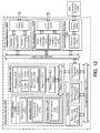
- FIG. 2 illustrates a block diagram of an example traffic database manager 200 architecture.
- traffic database manager 200's example architecture includes traffic database logic 210, control logic 220, memory 230, input/output (I/O) interfaces 240 and optionally one or more applications 250.
- traffic database logic 210 is coupled to control logic 220, memory 230 and I/O interfaces 240.
- the optional applications 250 are arranged in cooperation with control logic 220.
- Traffic database logic 210 may further include one or more of a fixed feature 212, a periodic feature 214, a query feature 216 and a traffic-flow module feature 218, or any reasonable combination thereof.
- traffic database logic 210 and control logic 220 may each or collectively represent a wide variety of logic device(s) to implement the features of traffic database manager 200.
- a logic device may include a computer, a microprocessor, a microcontroller, a field programmable gate array (FPGA), an application specific integrated circuit (ASIC), a sequestered thread or a core of a multi-core/multi-threaded microprocessor or a combination thereof.
- traffic database logic 210 includes fixed feature 212, periodic feature 214, query feature 216 and traffic flow model feature 218.
- Traffic database logic 210 may be configured to use one or more of these features to perform several operations.
- Example operations may include one or more of maintaining traffic database 112 by receiving or obtaining substantially fixed and periodically updated information or responding to a query received from a query source (e.g., query source(s) 140).
- the operations may also include generating a traffic flow model to provide traffic flow information based on information obtained from traffic database 112 and/or query information received from the query source.
- control logic 220 may be configured to control the overall operation of traffic database manager 200. As mentioned above, control logic 220 may represent any of a wide variety of logic device(s) configured to operate in conjunction with executable content or instructions to implement the control of traffic database manager 200. In alternate examples, the features and functionality of control logic 220 may be implemented within traffic database logic 210.
- memory 230 is arranged to store executable content or instructions.
- the executable content or instructions may be used by control logic 220 and/or traffic database logic 210 to implement or activate features or elements of traffic database manager 200.
- Memory 230 may also temporarily maintain traffic lane characteristics obtained by traffic database logic 210's features in response to a query to traffic database 112.
- Memory 230 may also temporarily maintain query information and the traffic lane characteristics to generate a traffic flow model to provide traffic flow information to the source of the query (e.g., query source(s) 140).
- Memory 230 may include a wide variety of memory media including, but not limited to, volatile memory, non-volatile memory, flash, programmable variables or states, random access memory (RAM), read-only memory (ROM), or other static or dynamic storage media.
- volatile memory non-volatile memory
- flash programmable variables or states
- RAM random access memory
- ROM read-only memory
- I/O interfaces 240 may provide an interface via an internal communication medium or link (not shown) between traffic database manager 200 and elements resident on or located with traffic database server 110.
- I/O interfaces 240 include interfaces that may operate according to various communication protocols to communicate over the internal communication link (e.g., Inter-Integrated Circuit (I 2 C), System Management Bus (SMBus) or Serial Peripheral Interface Bus (SPI), etc.).
- I/O interfaces 240 may also provide an interface between traffic database manager 200 and elements remote to traffic database server 110.
- traffic database server 110 may couple to elements of system 100 via communication link(s) 150.
- I/O interfaces 240 include an interface that operates according to various communication protocols to allow traffic database manager 200 to communicate over communication link(s) 150 (e.g., Code Division Multiple Access 2000 (CDMA2000), Global System for Mobile Communications (GSM), Ethernet, Asynchronous Transfer Mode (ATM), Synchronous Optical Networking (SONET), etc.).
- CDMA2000 Code Division Multiple Access 2000
- GSM Global System for Mobile Communications
- ATM Asynchronous Transfer Mode
- SONET Synchronous Optical Networking
- traffic database manager 200 includes one or more applications 250 to provide instructions to control logic 220 and/or traffic database logic 210.
- FIG. 3 illustrates an example block diagram of a query manager 300 architecture.
- query manager 300's example architecture includes query logic 310, control logic 320, memory 330, input/output (I/O) interfaces 340 and optionally one or more applications 350.
- query logic 310 is coupled to control logic 320, memory 330 and I/O interfaces 340.
- the optional applications 350 are arranged in cooperation with control logic 320.
- Query logic 310 may further include a characteristic feature 312, location feature 314 and traffic-flow module feature 316.
- the elements portrayed in FIG. 3 's block diagram are those elements to support or enable query manager 300 as described in this disclosure, although a given query manager may include some, all or more elements than those depicted in FIG. 3 .
- query logic 310 and control logic 320 may each or collectively represent a wide variety of logic device(s) to implement the features of query manager 300.
- a logic device for example, may include a computer, a microprocessor, a microcontroller, an FPGA, an ASIC, a sequestered thread or a core of a multi-core/multi-threaded microprocessor or a combination thereof.
- query logic 310 includes characteristic feature 312, location feature 314 and traffic flow model feature 316.
- Query logic 310 may be configured to use these features to perform several operations.
- Example operations may include placing a query to a traffic database (e.g., traffic database 112), the query to include information to indicate a start and an end location for a vehicle to travel and to also indicate one or more characteristics of the vehicle.
- the operations may also include generating a traffic flow model to provide traffic flow information to the vehicle.
- the traffic flow model for example, is based on traffic lane characteristics obtained from the traffic database and the query information.
- control logic 320 may control the overall operation of query manager 300 and as mentioned above, may represent any of a wide variety of logic device(s) configured to operate in conjunction with executable content or instructions to implement the control of query manager 300. In alternate examples, the features and functionality of control logic 320 may be implemented within query logic 310.
- memory 330 may include a wide variety of memory media. According to some examples, memory 330 is arranged to store executable content or instructions. The executable content or instructions may be used by control logic 320 and/or query logic 310 to implement or activate features or elements of query manager 300. Memory 330 may also temporarily maintain traffic lane characteristics obtained or received by query logic 310's features in response to a query to a traffic database. Memory 330 may also be arranged to temporarily maintain the query information and the traffic lane characteristics to enable query logic 310's features to generate a traffic flow model. The traffic flow model, for example, may be at least temporarily maintained in memory 330 in order to provide traffic flow information for a determination of a per-lane route for a vehicle to travel.
- I/O interfaces 340 may provide an interface via an internal communication medium or link (not shown) between query manager 300 and elements resident on or located with query source(s) 140. I/O interfaces 340 may also provide an interface between query manager 300 and elements remote to query source(s) 140.
- query manager 300 includes one or more applications 350 to provide instructions to control logic 320 and/or query logic 310.
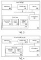
- FIG. 4 illustrates an example block diagram of a per-lane route manager 400 architecture.
- per-lane route manager 400's example architecture includes route logic 410, control logic 420, memory 430, input/output (I/O) interfaces 440 and optionally one or more applications 450.
- route logic 410 is coupled to control logic 420, memory 430 and I/O interfaces 440.
- the optional applications 450 are arranged in cooperation with control logic 420.
- Route logic 410 may further include a determine feature 412 and a present feature 414.
- route logic 410 and control logic 420 may each or collectively represent a wide variety of logic device(s) to implement the features of per-lane route manager 400.
- a logic device may include a computer, a microprocessor, a microcontroller, an FPGA, an ASIC, a sequestered thread or a core of a multi-core/multi-threaded microprocessor or a combination thereof.
- route logic 410 includes determination feature 412 and present feature 414.
- route logic 410 may be configured to use these features to perform several operations.
- Example operations may include determining a per-lane route for a vehicle to travel in response to receiving or obtaining traffic flow information. The operations may also include providing or presenting the per-lane route for the vehicle to travel to an occupant of the vehicle.
- control logic 420 may control the overall operation of route manager 400 and as mentioned above, may represent any of a wide variety of logic device(s) configured to operate in conjunction with executable content or instructions to implement the control of route manager 400. In alternate examples, the features and functionality of control logic 420 may be implemented within route logic 410.
- memory 430 may include a wide variety of memory media. According to some examples, memory 430 is arranged to store executable content or instructions. The executable content or instructions may be used by control logic 420 and/or route logic 410 to implement or activate features or elements of route manager 400. Memory 430 may also temporarily maintain traffic flow information for a vehicle obtained by route logic 410's features in response to receiving the traffic flow information, e.g., from query manager 300. Memory 430 may also temporarily maintain a per-lane route for the vehicle to travel in order to provide the per-lane route to an occupant of the vehicle.
- I/O interfaces 440 may provide an interface via an internal communication medium or link (not shown) between route manager 400 and elements resident on or located with query source(s) 140. I/O interfaces 440 may also provide an interface between route manager 400 and elements remote to query source(s) 140.
- route manager 400 includes one or more applications 450 to provide instructions to control logic 420 and/or route logic 410.
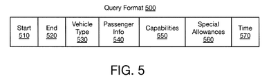
- FIG. 5 illustrates an example query format 500 to depict how query information may be conveyed in a query to a traffic database (e.g., traffic database 112).
- query format 500 includes fields 510, 520, 530, 540, 550 and 560. These fields, for example, include at least a portion of the query information for the query to the traffic database.
- a traffic flow model may be generated based on the query information and traffic lane characteristics obtained from the traffic database. The traffic flow model may then be used to provide traffic flow information to the source of the query information.
- Fields 510 and 520 may indicate start and end location information, respectively.
- the start location included in field 510 may indicate the starting point for a vehicle to travel. This starting point, for example, may indicate the location of the vehicle at or near the time the query is made.
- Start location information for example, includes, but is not limited to, geophysical location information obtained through a GPS receiver or other type of locating device. Start location information may also include location information obtained from a map or an address book.
- the end location included in field 520 may indicate the final or desired destination of the vehicle. End location information, for example, includes, but is not limited to, map grid coordinates, street addresses, road intersections, points of interest, cities, towns, parks and neighborhoods.
- a query may not need an explicit start point in the query to indicate a start location. Rather, the start location may be indicated in other ways.
- logic maintained at or with a traffic database e.g., traffic database logic 210) may be configured to determine the start location associated with the query. This determination may be based on location characteristics associated with how the query was conveyed to the traffic database via communication link(s) 150. For example, if communication link(s) 150 included a wireless communication link and the source of the query was located at or with a vehicle, the network that enabled the wireless communication to convey the query may also track the location of where the source of the query originated. The tracking information may then be added to the query in indicate the start location.
- the location of the query may be presumed close enough to the point of entry in the network (e.g., a wireless access point) so that the location of the access point itself can serve as a default start location.
- Field 530 indicates a vehicle type.
- the vehicle type includes, but is not limited to, cars, trucks, buses or motorcycles.
- Field 540 may include information to indicate whether the vehicle contains or will contain passengers.
- Field 550 includes information to indicate capabilities of the vehicle. Capabilities may include, but are not limited to, two-wheel drive, four-wheel drive, tire-traction capable, height clearance and turning radius.
- Field 560 includes information to indicate applicable special allowances. In some examples, special allowances may indicate that a vehicle is a low emission vehicle (e.g., electric, hybrid, etc.) or an alternative fuel vehicle (e.g., bio-fuels such as ethanol or bio-diesel). In other examples, special allowances may indicate that a vehicle is transporting hazardous cargo such as explosives or toxic chemicals.
- Field 570 may include the time of the query or may indicate the time the vehicle plans or anticipates traveling from the start location to the end location.
- FIG. 6 illustrates a table 600 to depict example traffic lane characteristics maintained in a traffic database (e.g., traffic database 112).
- the contents of table 600 may be maintained by traffic database manager 200 and may be used along with query information to generate a traffic flow model in order to provide traffic flow information to the source of the query.
- traffic lane characteristics for northbound road segment 605 include fixed characteristics 610, 615, 620, 625, 630, 635, 640 and include periodic characteristics 645, 650, 655, 660 and 665 for each of three traffic lanes 605a, 605b and 605c.
- Northbound road segment 605 may be an example of a portion of an expressway or highway.
- the outgoing transition point for northbound road segment 605 may be the end of the expressway or a portion of the expressway or highway that enters an area with traffic lights and reduced speed limits.
- Table 600 is provided as an example of possible contents of a traffic database for a road segment.
- the number of lanes for the road segment and associated fixed/periodic characteristics may include any number of lanes and/or associated fixed/periodic characteristics.
- a similar table may exist for a southbound road segment 605.
- traffic lane characteristics for any number of road segments, for example, can be maintained in the traffic database.
- fixed characteristics 610, 615, 620, 625, 630, 635 and 640 may be based on substantially fixed information and as mentioned above, may change infrequently.
- fixed characteristics 610, 615, 620, 625, 630, 635 and 645 include traffic lane characteristics associated with traffic lanes 605a-c.
- Fixed characteristic 610 may includes lane position information.
- Fixed characteristic 615 and 620 may include lane restriction information.
- Fixed characteristic 625 may include congestion information. Congestion information, for example, may indicate possible or likely congestion at certain times of the day based on historical traffic flow information. Congestion during typical rush hour times associated with morning and evening commutes is but one example of historical traffic flow information that may indicate congestion.
- Fixed characteristic 630 may include traffic lane special allowances.
- the traffic lane special allowances may include unrestricted HOV traffic lane times, allowed HOV lane use for non-passenger, low emission vehicles and travel prohibition on all lanes for vehicles transporting hazardous cargo or exceeding a given height (e.g., for a route segment through a tunnel), although this disclosure is not limited to only the above listed types of special allowances.
- Fixed characteristics 635 may include information to indicate an incoming transition point of northbound road segment 605.
- the incoming transition point may include a part of a northbound road segment 605 that connects or couples to another road segment.
- an on-ramp may be an incoming transition point to northbound road segment 605.
- traffic lane 605c (right lane) may be the only traffic lane that has this transition point if traffic enters northbound road segment 605 via the right lane.
- Fixed characteristics 640 may include information to indicate an outgoing transition point of northbound road segment 605.
- the outgoing transition point may include a part of a northbound road segment 605 that connects or couples to another road segment.
- an outgoing transition point may be an intersection were northbound road segment 605 may connect or couple with one or more other road segments.
- the intersection may include a stop sign, traffic light, roundabout or other type of traffic control measure.
- an outgoing transition point may include a left-hand turn at an intersection. A left-hand turn may only impact traffic lane 605a (left lane) and the information in fixed characteristics 640 may indicate that impact.
- periodic characteristics 645, 650, 655, 660 and 665 may be based on periodically updated information and as mentioned above, may change frequently. As shown in FIG. 6 , periodic characteristics 645, 650, 655, 660 and 665 include traffic lane characteristics associated with traffic lanes 605a-c. Period characteristic 645 may include incoming transition point information. Incoming transition point information may indicate the amount of time or delays in passing through the incoming transition point. As previously mentioned above, northbound road segment 605 may be a highway or expressway, thus an incoming transition point may include an on-ramp. Also, although a vehicle may enter northbound road segment 605 via traffic lane 605c, the vehicle may have to cross traffic lane 605c to enter traffic lanes 605a and 605b.
- periodic characteristic 650 may include outgoing transition point information.
- Outgoing transition point information may indicate the amount of time or delays in passing through the outgoing transition point.
- northbound road segment 605 has an outgoing transition point that marks an end or a portion of an expressway or a highway that enters an area with traffic lights and reduced speed limits. Since the outgoing transition point indicates an area where the expressway or highway passes through traffic lights, delays due to traffic light congestion or left hand turns may be indicated in periodic characteristic 650.
- Periodic characteristic 655 includes road sensor data or information.
- This road sensor data indicates real-time or near real-time traffic speeds for a particular traffic lane.
- the road sensor data may also include the average speeds of all or a portion of the lanes in a road segment.
- periodic characteristic 660 for example, includes information indicating traffic lane alerts such as accidents, construction or stalled vehicles. Traffic lane alerts, in some embodiments, may indicate a possible impact on the traffic flow through a traffic lane.
- Periodic characteristic 665 for example, includes traffic flow data reported from vehicles that are traveling on or have recently traveled through the road segment. Traffic flow data may include, but is not limited to, speeds of the reporting vehicles, wait times at stoplights and a general description of movement (e.g., stop and go, steady speeds, relatively free movement, etc.).
- FIG. 7A illustrates an example traffic flow model 700.
- Traffic flow model 700 was generated based on a vehicle's characteristics and traffic lane characteristics associated with a prospective route for the vehicle to travel.
- the vehicle's characteristics were obtained from query information conveyed in query format 500.
- vehicle characteristics may indicate start and end locations for the vehicle to travel and may also indicate other vehicle characteristics such as vehicle type.
- the locations indicated in the query information may encompass a route that includes all or a portion of northbound road segment 605.
- the traffic lane characteristics associated with at least a portion of the prospective route may be included with the traffic lane characteristics maintained in a traffic database (see FIG. 6 ).
- the query information indicated a car vehicle type with no passengers, no low emissions and a query time that falls within an HOV restriction time.
- FIG. 7B and FIG. 7C illustrate an example program code 710 to generate traffic flow model 700.
- traffic flow model 700 was generated using a traffic flow algorithm depicted as program code 710 in FIGS. 7B and 7C , although this disclosure is not limited to this example program code 710.
- Inputs, for example to the traffic flow algorithm that generated traffic flow model 700 were based on at least a portion of the traffic lane characteristics of traffic lanes 605a-c and on at least a portion of the query information conveyed in query format 500.
- logic, in either traffic database manager 200 or query manager 300 may implement or execute program code 710 for each of the three traffic lanes of road segment 605 to generate traffic flow model 700.
- traffic flow information for traffic lanes 605a-c may be provided.
- traffic flow model 700 indicates that traffic lane 605a is restricted for travel by the vehicle associated with the query and that traffic lanes 605b and 605c are not restricted to the vehicle.
- Traffic flow model 700 also includes a traffic lane alert for traffic lane 605c. The traffic lane alert may indicate an accident, construction or a stalled vehicle in traffic lane 605c.
- Traffic flow model 700 may further indicate incoming transition point delay times that are the same for traffic lanes 605a-c. As previously mentioned above for FIG. 6 , the incoming transition point delay may be based on delay times to enter traffic lane 605c via an on-ramp. Also, as mentioned above, since the outgoing transition point for road segment 605 marks the end of higher speed limits and no traffic lights, traffic flow model 700 indicates separate outgoing transition point delay times for traffic lanes 605a-c. The separate outgoing transition point delays may indicate traffic light delays and/or left hand turn delays. Traffic flow model 700 may also include a separate indication of an estimated travel time for traffic lanes 605a-c. In some examples, logic, in either traffic database manager 200 or query manager 300 may be configured to determine an estimated travel time for a traffic lane based on speed sensor data, reports from vehicles and incoming/outgoing transition point delay times.
- traffic flow information in traffic flow model 700 may be used or provided to facilitate a determination of which traffic lanes in road segment 605 (if any) will be at least a part of a path included in a per-lane route for the vehicle to travel.
- traffic flow model 700 indicates that traffic lane 605a is restricted, traffic lane 605c has a traffic lane alert and the estimated travel time for traffic lane 605b is smaller than for traffic lane 605c.
- traffic flow information provided by traffic flow model 700 a determination that traffic lane 605b may be the best or fastest route through road segment 605 is likely or probable.
- a traffic flow model may be provided that includes information pertaining to traffic lanes for which a vehicle is eligible to travel. For example, since the vehicle type for the query that lead to the generation of traffic flow model 700 included no passengers, the vehicle is not eligible or restricted from traveling on traffic lane 605a.
- logic, in either traffic database manager 200 or query manager 300 may implement program code 710, but will exclude information related to traffic lane 605a from a generated traffic flow model.
- traffic flow model 700 may be combined with other traffic flow models for one or more other road segments to provide traffic flow information to the vehicle associated with the query.
- the other traffic flow models may be generated in a similar manner to how traffic flow model 700 was generated.
- This traffic flow information may also facilitate a determination of a path included in a per-lane route for the vehicle to travel. The path, for example, could result in the vehicle changing traffic lanes as the vehicle enters or exits locations encompassed within the other road segments.
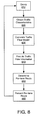
- FIG. 8 illustrates a flow chart of an example method to provide traffic flow information to determine a per-lane route for a vehicle to travel.
- system 100 as described in FIG. 1 , is used to describe this method, although this method is not limited to only an implementation on system 100. The method, for example, may be implemented on other systems that may include at least a portion of the elements of system 100.
- query begins in block 810 (Query), where a query from query source(s) 140 is made to traffic database 112 maintained at traffic database server 110.
- This query may be in the form of query format 500 and may be provided by query manager 300 via communication link(s) 150.
- query format 500 includes query information that may indicate characteristics for a vehicle. These vehicle characteristics, for example, may indicate a start location and an end location for the vehicle to travel as well as a vehicle type.
- traffic database manager 200 receives the query and obtains traffic lane characteristics associated with a route between the start location and the end location indicated in the query information.
- the route includes route segment 605 as described for FIG. 6 .
- the traffic lane characteristics depicted in FIG. 6 may be obtained from traffic database 112.
- the process may generate a traffic flow model.
- the traffic flow model may be based on the traffic lane characteristics obtained by elements of traffic database manager 200 (e.g., traffic database logic 210).
- the traffic flow model may be generated by elements of traffic database manager 200 (e.g., traffic database logic 210).
- elements of query manager 300 e.g., query logic 310) generate the traffic flow model.
- One or more traffic flow algorithms may be implemented to generate a traffic flow model for traffic lanes 605a-c. The one or more traffic flow algorithms may be similar to the traffic flow algorithm described above for program code 710.
- traffic flow information for the vehicle based on the traffic flow model may be provided to the source of the query.
- the traffic flow information may indicate traffic flow information for each of traffic lanes 605a-c.
- the traffic flow information may include information for unrestricted traffic lanes for which the vehicle is eligible to travel. Thus, in this alternative, information for restricted traffic lane(s) is not provided.
- the process determines a per-lane route for the vehicle to travel.
- the determination may be in response to receiving the traffic flow information.
- the traffic flow information for example, facilitates a determination of which traffic lane or traffic lane path provides the best per-lane route (e.g., has the fastest prospective travel time) between the start location and the end location.
- elements of per-lane route manager 400 e.g., route logic 410) may determine the best per-lane route.
- per-lane route manager 400 may be located at a query source(s) 140 that is remote to the vehicle.
- a per-lane route manager 400 located remotely may present the per-lane route to an occupant of the vehicle over a wired or wireless communication medium coupled to a network that includes, but is not limited to, a LAN, WLAN, WAN, WWAN, MAN, PAN, a cellular or wireless broadband telephony network and a satellite network.
- Remote presentation may include turn-by-turn voice guidance or may include transmitting the per-lane route for eventual display by a display system (e.g., a navigation system, a wireless phone, a handheld computer, a portable computer, etc.) located at, with or in the vehicle.
- a display system e.g., a navigation system, a wireless phone, a handheld computer, a portable computer, etc.
- per-lane route manager 400 may be located at a query source(s) 140 located at, with or in the vehicle. Presentation, in this other example, may also include turn-by-turn voice guidance or providing the per-lane route for eventual display by a display system.
- another query may be initiated due to events occurring while the vehicle is traveling the per-lane route (e.g., an accident, stalled vehicle or unexpected congestion).
- the process returns to block 810 and a new per-lane route including a path through a different road segment and/or traffic lane may be determined and presented to an occupant of the vehicle.
- FIG. 9 illustrates a block diagram illustrating additional aspects of the example traffic flow information system 100 depicted in FIG. 1 and described above.
- query source 140a and query source 140b provide examples of at least two types of query sources that may place a query to a traffic database such as traffic database 112.
- traffic database manager 200 and table 600 may be located with or resident on traffic database server 110.
- traffic database manager 200 may include logic (e.g. traffic database logic 210 and/or control logic 220) to maintain traffic database 112.
- Traffic database 112 may include table 600 and as described above for FIG. 6 , table 600 may include traffic lane characteristics for a road segment 605. The traffic lane characteristics for road segment 605 may be based on substantially fixed and periodically updated information.
- traffic database manager 200 in response to receiving a query to traffic database 112 (e.g., from query source 140a or 140b), may provide traffic lane characteristics associated with the query.
- the provided traffic lane characteristics may include the characteristics depicted in table 600 and may enable the generation of a traffic flow model (e.g., traffic flow model 700).
- the traffic flow model may provide traffic flow information to the source of the query.
- query source 140a includes a navigation system 905 with a query manager 300 and a per-lane route manager 400. Also shown in FIG. 9 , is an example where query source 140b includes provider 910. Provider 910 may also have a query manager 300 and a per-lane route manager 400. Navigation system 905, in some embodiments, may be located at, with or in a vehicle for which a query is being placed. Provider 910, in some embodiments, may be located remotely to a vehicle for which a query is being placed (e.g. a provider of a navigation service).
- query manager 300 includes logic (e.g. query logic 310 and/or control logic 320) to place a query to a traffic database (e.g., traffic database 112).
- the query may include information to indicate a start location and an end location for a vehicle to travel.
- the query may also include an indication of a vehicle type.
- the traffic database may include traffic lane characteristics associated with a route between the start location and the end location (e.g., table 600).
- a traffic flow model (e.g., traffic flow model 700) may be generated based on the query and the traffic lane characteristics.
- the traffic flow model may provide traffic flow information for the route between the start location and the end location.
- Per-lane route manager 400 may include logic (e.g., route logic 410 and/or control logic 420). Responsive to receiving the traffic flow information, per-lane route manager 400's logic may be configured to determine a per-lane route including a path for the vehicle to travel and may present or provide an indication of the per-lane route to an occupant of the vehicle.
- logic e.g., route logic 410 and/or control logic 420. Responsive to receiving the traffic flow information, per-lane route manager 400's logic may be configured to determine a per-lane route including a path for the vehicle to travel and may present or provide an indication of the per-lane route to an occupant of the vehicle.
- per-lane route manager 400 may be located with the vehicle resident in navigation system 905. In these embodiments, per-lane route manager 400 may be configured to present the per-lane route to the occupant through navigation system 905. Presentation may include turn-by-turn voice guidance and/or providing an indication of the per-lane route for eventual display to the occupant.
- per-lane route manager 400 may be located remotely to the vehicle in provider 910. In these other embodiments, per-lane route manager 400 may be configured to remotely present the per-lane route to the occupant through provider 910 via a wired or wireless communication medium coupled to a network. Remote presentation may include transmitting turn-by-turn voice guidance or may include transmitting data associated with the per-lane route for eventual display of the per-lane route by a display system located at, with or in the vehicle.
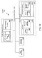
- FIG. 10 illustrates another block diagram illustrating additional aspects of the example traffic flow information system 100.
- System 100 as shown in FIG. 10 , for example, provides more detail of query source(s) 140.
- query source(s) 140 includes a provider 1005 and a navigation system 1010.
- Provider 1005 may be located remotely to a vehicle for which a query is being placed (e.g. a provider of a navigation service).
- Navigation system 1010 may be located at, with or in a vehicle for which a query is being placed.
- Provider 1005 and navigation system 1010 may be either one query source or can be two separate query sources.
- provider 1005 includes a query manager 300 and may also include a per-lane route manager 400.
- Navigation system 1010 may include a per-lane route manager 400 and may also include a query manager 300.
- the dotted-box around per-lane route manager 400 in provider 1005 and around query manager 300 in navigation system 1010 may indicate that query manager 300 and per-lane route manager 400 may be co-located either with provider 1005 or with navigation system 1010.
- the dotted-box may also indicate that query manager 300 can be located with provider 1005 and per-lane route manager 400 can be located with navigation system 1010.
- logic included in query manager 300 configured to place a query and logic included in per-lane route manger 400 configured to determine a per-lane route and present the per-lane route may be located with provider 1005, navigation system 1010 or a combination thereof.
- FIG. 11 illustrates a block diagram of an example computer program product 1100.
- computer program product 1100 includes a signal bearing medium 1102 that may also include instructions 1104.
- the query may include providing information to include an indication of a start location and an end location for a vehicle to travel and an indication of a vehicle type.
- the traffic database may include traffic lane characteristics associated with a route between the start location and the end location. Traffic flow information may then be received from the traffic database.
- the traffic flow information may have been generated by the traffic database responsive to the database query using a traffic flow model, and the traffic lane characteristics to provide traffic flow information for the route between the start location and the end location.
- Instructions 1104 may further cause the computer to determine a per-lane route for the vehicle to travel in response to receiving the traffic flow information.
- Instruction 1104 may also cause the computer to present the per-lane route for the vehicle to travel to an occupant of the vehicle.
- the dotted boxes around these elements may depict different types of mediums included within, but not limited to, signal bearing medium 1102. These types of mediums may distribute instruction 1104 to be executed by a computer.
- Computer readable medium 1106 and recordable medium 1108, for example, may include, but are not limited to, a flexible disk, a hard disk drive, a Compact Disc (CD), a Digital Video Disk (DVD), a digital tape, a computer memory, etc.
- Communications medium 1110 for example, may include, but is not limited to, a digital and/or an analog communication medium (e.g., a fiber optic cable, a waveguide, a wired communication link, a wireless communication link, etc.).
- FIG. 12 is a block diagram illustrating an example computing device 1200.
- traffic database manager 200, query manager 300 and/or per-lane route manager 400 depicted in FIGS. 2-4 may be implemented on computing device 1200.
- elements of computing device 1200 may be arranged or configured to maintain and/or query a traffic database, generate a traffic flow model, provide traffic flow information, determine a per-lane and/or provide the per-lane route for a vehicle to travel.
- computing device 1200 typically includes one or more processors 1210 and system memory 1220.
- a memory bus 1230 can be used for communicating between the processor 1210 and the system memory 1220.
- processor 1210 can be of any type including but not limited to a microprocessor ( ⁇ P), a microcontroller ( ⁇ C), a digital signal processor (DSP), or any combination thereof.
- Processor 1210 can include one more levels of caching, such as a level one cache 1211 and a level two cache 1212, a processor core 1213, and registers 1214.
- the processor core 1213 can include an arithmetic logic unit (ALU), a floating point unit (FPU), a digital signal processing core (DSP Core), or any combination thereof.
- a memory controller 1215 can also be used with the processor 1210, or in some implementations the memory controller 1215 can be an internal part of the processor 1210.
- system memory 1220 can be of any type including but not limited to volatile memory (such as RAM), non-volatile memory (such as ROM, flash memory, etc.) or any combination thereof.
- System memory 1220 typically includes an operating system 1221, one or more applications 1222, and program data 1224.
- Application 1222 includes instructions 1223 that are arranged to perform the functions as described herein including the actions described with respect to traffic database manager 200, query manager 300 or per-lane route manager 400 architectures shown in FIGS. 2-4 or including the actions described with respect to the flow charts shown in FIG. 8 .
- Program Data 1224 includes traffic information data 1225 that is useful for implementing per-lane route instructions 1223 (e.g., query information, traffic lane characteristics, etc.).
- application 1222 can be arranged to operate with program data 1224 on an operating system 1221 such that implementations of maintaining and/or querying a traffic database, generating a traffic flow model, providing traffic flow information, determining a per-lane and providing the per-lane route for a vehicle to travel may be provided as described herein.
- This described basic configuration is illustrated in FIG. 12 by those components within dashed line 1201.
- Computing device 1200 can have additional features or functionality, and additional interfaces to facilitate communications between the basic configuration 1201 and any required devices and interfaces.
- a bus/interface controller 1240 can be used to facilitate communications between the basic configuration 1201 and one or more data storage devices 1250 via a storage interface bus 1241.
- the data storage devices 1250 can be removable storage devices 1251, non-removable storage devices 1252, or a combination thereof.
- removable storage and non-removable storage devices include magnetic disk devices such as flexible disk drives and hard-disk drives (HDD), optical disk drives such as compact disk (CD) drives or digital versatile disk (DVD) drives, solid state drives (SSD), and tape drives to name a few.
- Example computer storage media can include volatile and nonvolatile, removable and non-removable media implemented in any method or technology for storage of information, such as computer readable instructions, data structures, program modules, or other data.
- Computer storage media includes, but is not limited to, RAM, ROM, EEPROM, flash memory or other memory technology, CD-ROM, digital versatile disks (DVD) or other optical storage, magnetic cassettes, magnetic tape, magnetic disk storage or other magnetic storage devices, or any other medium which can be used to store the desired information and which can be accessed by computing device 1200. Any such computer storage media can be part of device 1200.
- Computing device 1200 can also include an interface bus 1242 for facilitating communication from various interface devices (e.g., output interfaces, peripheral interfaces, and communication interfaces) to the basic configuration 1201 via the bus/interface controller 1240.
- Example output interfaces 1260 include a graphics processing unit 1261 and an audio processing unit 1262, which can be configured to communicate to various external devices such as a display or speakers via one or more A/V ports 1263.
- Example peripheral interfaces 1260 include a serial interface controller 1271 or a parallel interface controller 1272, which can be configured to communicate with external devices such as input devices (e.g., keyboard, mouse, pen, voice input device, touch input device, etc.) or other peripheral devices (e.g., printer, scanner, etc.) via one or more I/O ports 1273.
- An example communication interface 1280 includes a network controller 1281, which can be arranged to facilitate communications with one or more other computing devices 1290 over a network communication via one or more communication ports 1282.
- a network communication connection is one example of a communication media.
- Communication media may typically be embodied by computer readable instructions, data structures, program modules, or other data in a modulated data signal, such as a carrier wave or other transport mechanism, and includes any information delivery media.
- a "modulated data signal" can be a signal that has one or more of its characteristics set or changed in such a manner as to encode information in the signal.
- communication media can include wired media such as a wired network or direct-wired connection, and wireless media such as acoustic, radio frequency (RF), infrared (IR) and other wireless media.
- RF radio frequency
- IR infrared
- computer readable media can include both storage media and communication media.
- Computing device 1200 can be implemented as a portion of a small-form factor portable (or mobile) electronic device such as a cell phone, smart phone, a personal data assistant (PDA), a personal media player device, a wireless web-watch device, a personal headset device, an application specific device, or a hybrid device that include any of the above functions.
- a small-form factor portable (or mobile) electronic device such as a cell phone, smart phone, a personal data assistant (PDA), a personal media player device, a wireless web-watch device, a personal headset device, an application specific device, or a hybrid device that include any of the above functions.
- Computing device 1200 can also be implemented as a personal computer including both laptop computer and non-laptop computer configurations or implemented in a workstation or a server configuration.
- references made in this disclosure to the term “responsive to” or “in response to” are not limited to responsiveness to only a particular feature and/or structure.
- a feature may also be responsive to another feature and/or structure and also be located within that feature and/or structure.
- terms or phrases such as “coupled” or “responsive” or “in response to” or “in communication with”, etc. are used herein or in the claims that follow, these terms should be interpreted broadly.
- the phrase “coupled to” may refer to being communicatively, electrically and/or operatively coupled as appropriate for the context in which the phrase is used.
- a typical data processing system generally includes one or more of a system unit housing, a video display device, a memory such as volatile and non-volatile memory, processors such as microprocessors and digital signal processors, computational entities such as operating systems, drivers, graphical user interfaces, and applications programs, one or more interaction devices, such as a touch pad or screen, and/or control systems including feedback loops and control motors (e.g., feedback for sensing position and/or velocity; control motors for moving and/or adjusting components and/or quantities).
- a typical data processing system may be implemented utilizing any suitable commercially available component, such as those typically found in data computing/communication and/or network computing/communication systems.
- any two components so associated can also be viewed as being “operably connected”, or “operably coupled”, to each other to achieve the desired functionality, and any two components capable of being so associated can also be viewed as being “operably couplable”, to each other to achieve the desired functionality.
- operably couplable include but are not limited to physically mateable and/or physically interacting components and/or wirelessly interactable and/or wirelessly interacting components and/or logically interacting and/or logically interactable components.
Landscapes
- Physics & Mathematics (AREA)
- Engineering & Computer Science (AREA)
- Radar, Positioning & Navigation (AREA)
- Remote Sensing (AREA)
- General Physics & Mathematics (AREA)
- Automation & Control Theory (AREA)
- Mathematical Physics (AREA)
- Traffic Control Systems (AREA)
Applications Claiming Priority (1)
| Application Number | Priority Date | Filing Date | Title |
|---|---|---|---|
| US12/400,631 US8838370B2 (en) | 2009-03-09 | 2009-03-09 | Traffic flow model to provide traffic flow information |
Publications (3)
| Publication Number | Publication Date |
|---|---|
| EP2228779A2 true EP2228779A2 (de) | 2010-09-15 |
| EP2228779A3 EP2228779A3 (de) | 2010-11-17 |
| EP2228779B1 EP2228779B1 (de) | 2016-01-27 |
Family
ID=42405402
Family Applications (1)
| Application Number | Title | Priority Date | Filing Date |
|---|---|---|---|
| EP10155669.4A Not-in-force EP2228779B1 (de) | 2009-03-09 | 2010-03-05 | Verkehrsflussmodell zur Bereitstellung von Verkehrsflussinformationen |
Country Status (2)
| Country | Link |
|---|---|
| US (3) | US8838370B2 (de) |
| EP (1) | EP2228779B1 (de) |
Cited By (13)
| Publication number | Priority date | Publication date | Assignee | Title |
|---|---|---|---|---|
| WO2017087199A1 (en) * | 2015-11-19 | 2017-05-26 | Amazon Technologies, Inc. | Lane assignments for autonomous vehicles |
| EP3214407A1 (de) * | 2016-03-01 | 2017-09-06 | Alpine Electronics, Inc. | Navigationsvorrichtung und verfahren zur bereitstellung von fahrspurnutzungsanweisung |
| US10338591B2 (en) | 2016-11-22 | 2019-07-02 | Amazon Technologies, Inc. | Methods for autonomously navigating across uncontrolled and controlled intersections |
| US11290856B2 (en) | 2020-03-31 | 2022-03-29 | Toyota Motor North America, Inc. | Establishing connections in transports |
| US11474530B1 (en) | 2019-08-15 | 2022-10-18 | Amazon Technologies, Inc. | Semantic navigation of autonomous ground vehicles |
| US11735048B2 (en) | 2020-02-27 | 2023-08-22 | Toyota Motor North America, Inc. | Minimizing traffic signal delays with transports |
| US11873000B2 (en) | 2020-02-18 | 2024-01-16 | Toyota Motor North America, Inc. | Gesture detection for transport control |
| US12033502B2 (en) | 2020-03-31 | 2024-07-09 | Toyota Motor North America, Inc. | Traffic manager transports |
| US12162516B2 (en) | 2020-02-18 | 2024-12-10 | Toyota Motor North America, Inc. | Determining transport operation level for gesture control |
| US12203773B1 (en) | 2022-06-29 | 2025-01-21 | Amazon Technologies, Inc. | Visual localization for autonomous ground vehicles |
| US12430889B2 (en) | 2020-02-18 | 2025-09-30 | Toyota Motor North America, Inc. | Distinguishing gesture actions among transport occupants |
| US12461228B1 (en) | 2022-08-29 | 2025-11-04 | Amazon Technologies, Inc. | Radar-inertial odometry for autonomous ground vehicles |
| US12528509B2 (en) | 2020-03-31 | 2026-01-20 | Toyota Motor North America, Inc. | Identifying roadway concerns and taking preemptive actions |
Families Citing this family (34)
| Publication number | Priority date | Publication date | Assignee | Title |
|---|---|---|---|---|
| DE102005039103A1 (de) * | 2005-08-18 | 2007-03-01 | Robert Bosch Gmbh | Verfahren für die Erfassung eines Verkehrsraums |
| EP2545539A4 (de) | 2010-03-11 | 2017-12-27 | Inrix, Inc. | Erlernung von strassennavigationspfaden auf basis gesammelter fahrerverhaltensweisen |
| US8972171B1 (en) * | 2010-04-09 | 2015-03-03 | Google Inc. | Collective vehicle traffic routing |
| US8909462B2 (en) | 2011-07-07 | 2014-12-09 | International Business Machines Corporation | Context-based traffic flow control |
| DE102011082123A1 (de) * | 2011-09-05 | 2013-03-07 | Robert Bosch Gmbh | Verfahren zum Betreiben eines Fahrzeuges |
| US20130116995A1 (en) * | 2011-11-09 | 2013-05-09 | Xerox Corporation | Agent-based road transportation modeling and simulation method and system |
| CN103245351A (zh) * | 2012-02-07 | 2013-08-14 | 英华达(上海)科技有限公司 | 可弹性调整路径规划的导航方法及其装置 |
| CN103365886B (zh) | 2012-03-31 | 2016-07-06 | 国际商业机器公司 | 车联网中的空间事件的查询方法和优化查询器 |
| US9964414B2 (en) | 2013-03-15 | 2018-05-08 | Caliper Corporation | Lane-level vehicle navigation for vehicle routing and traffic management |
| US9024787B2 (en) * | 2013-09-18 | 2015-05-05 | Lenovo Enterprise Solutions (Singapore) Pte. Ltd. | Controlling vehicular traffic on a one-way roadway |
| US9582999B2 (en) * | 2013-10-31 | 2017-02-28 | Here Global B.V. | Traffic volume estimation |
| TWI453692B (zh) * | 2013-11-01 | 2014-09-21 | Chih Cheng Lin | 動力車輛之車上端資料庫管理系統 |
| WO2015134311A1 (en) * | 2014-03-03 | 2015-09-11 | Inrix Inc | Traffic obstruction detection |
| JP6224494B2 (ja) * | 2014-03-17 | 2017-11-01 | 株式会社東芝 | 設定更新システム、走行車制御システム、設定更新方法及びコンピュータプログラム |
| JP6597033B2 (ja) * | 2015-08-03 | 2019-10-30 | アイシン・エィ・ダブリュ株式会社 | 推奨レーン決定システム、方法およびプログラム |
| US20170074667A1 (en) * | 2015-09-14 | 2017-03-16 | Michael H. Laur | Seasonal navigation system for automated vehicles |
| EP3179212A1 (de) * | 2015-12-11 | 2017-06-14 | C.R.F. Società Consortile Per Azioni | Kraftfahrzeug-fahrerassistenz zum durchfahren eines kreisverkehrs |
| US20190079786A1 (en) * | 2016-03-07 | 2019-03-14 | Entit Software Llc | Simulation environment creation |
| JP2017181392A (ja) * | 2016-03-31 | 2017-10-05 | アイシン・エィ・ダブリュ株式会社 | 経路探索装置及びコンピュータプログラム |
| US20180080788A1 (en) * | 2016-09-16 | 2018-03-22 | Intel IP Corporation | Navigation based on vehicle dimensions |
| CN106412048B (zh) * | 2016-09-26 | 2020-01-21 | 北京东土科技股份有限公司 | 基于智能交通云控制系统的信息处理方法及装置 |
| US10726640B2 (en) * | 2016-11-15 | 2020-07-28 | At&T Mobility Ii Llc | Facilitation of smart communications hub to support driverless vehicles in 5G networks or other next generation networks |
| CN108399766B (zh) * | 2017-02-08 | 2020-08-25 | 孟卫平 | 交通信号两维疏堵绿波模式控制方法 |
| US11016999B2 (en) | 2018-08-31 | 2021-05-25 | Here Global B.V. | Use of geographic database comprising lane level information for traffic parameter prediction |
| US11035686B2 (en) * | 2018-08-31 | 2021-06-15 | Here Global B.V. | Use of geographic database comprising lane level information for traffic parameter prediction |
| US12055401B1 (en) | 2018-08-31 | 2024-08-06 | Here Global B.V. | Use of geographic database comprising lane level information for traffic parameter prediction |
| CN110942622B (zh) * | 2018-09-21 | 2022-11-08 | 上海浦东建筑设计研究院有限公司 | 一种基于停车场实时运营大数据的停车场规划方法 |
| KR102467375B1 (ko) * | 2018-09-22 | 2022-11-16 | 구글 엘엘씨 | 개선된 트래픽 상황 시각화를 위한 시스템 및 방법 |
| DE102019211599A1 (de) * | 2019-08-01 | 2021-02-04 | Robert Bosch Gmbh | Trajektorienplanung eines Nutzfahrzeugs |
| CN111862588B (zh) * | 2019-12-18 | 2022-04-22 | 北京嘀嘀无限科技发展有限公司 | 控制信息发布的方法、装置、电子设备和存储介质 |
| CN114613135B (zh) * | 2022-03-06 | 2023-04-21 | 南京理工大学 | 考虑建筑场所影响的城市路网交通流预测方法及系统 |
| CN116010538A (zh) * | 2022-10-12 | 2023-04-25 | 上海滴滴沃芽科技有限公司 | 交通热力图生成方法、装置、设备、存储介质和程序产品 |
| CN116416806A (zh) * | 2023-06-12 | 2023-07-11 | 天津市政工程设计研究总院有限公司 | 一种智能网联自动驾驶货运专用道控制系统 |
| CN117854298B (zh) * | 2024-02-27 | 2024-06-18 | 青岛海信网络科技股份有限公司 | 一种区域交叉口的车辆通行方法和边缘计算设备 |
Citations (1)
| Publication number | Priority date | Publication date | Assignee | Title |
|---|---|---|---|---|
| EP0902405A2 (de) | 1997-09-11 | 1999-03-17 | Siemens Aktiengesellschaft | Verfahren zur Ermittlung von Verkehrsinformationen |
Family Cites Families (24)
| Publication number | Priority date | Publication date | Assignee | Title |
|---|---|---|---|---|
| US3876973A (en) * | 1973-03-13 | 1975-04-08 | William C Griebel | Method and apparatus for deterring wrong way drivers |
| US7295925B2 (en) * | 1997-10-22 | 2007-11-13 | Intelligent Technologies International, Inc. | Accident avoidance systems and methods |
| JPH10281790A (ja) * | 1997-04-08 | 1998-10-23 | Aisin Aw Co Ltd | 経路探索装置、ナビゲーション装置及びナビゲーション処理のためのコンピュータプログラムを記憶した媒体 |
| US8209120B2 (en) * | 1997-10-22 | 2012-06-26 | American Vehicular Sciences Llc | Vehicular map database management techniques |
| JP3808242B2 (ja) * | 1999-07-26 | 2006-08-09 | パイオニア株式会社 | 画像処理装置、画像処理方法及びナビゲーション装置 |
| US6490519B1 (en) * | 1999-09-27 | 2002-12-03 | Decell, Inc. | Traffic monitoring system and methods for traffic monitoring and route guidance useful therewith |
| US7375728B2 (en) * | 2001-10-01 | 2008-05-20 | University Of Minnesota | Virtual mirror |
| KR20020094545A (ko) * | 2001-06-12 | 2002-12-18 | 현대자동차주식회사 | 자동차의 차선 이탈 방지시스템 및 그 제어방법 |
| DE10146744A1 (de) * | 2001-09-22 | 2003-04-17 | Bosch Gmbh Robert | Verfahren und System zum Bereitstellen von Fahrspurempfehlungen |
| JP3885716B2 (ja) * | 2002-11-21 | 2007-02-28 | 日産自動車株式会社 | 車両用推奨操作量生成装置 |
| US7835858B2 (en) * | 2002-11-22 | 2010-11-16 | Traffic.Com, Inc. | Method of creating a virtual traffic network |
| US7860639B2 (en) * | 2003-02-27 | 2010-12-28 | Shaoping Yang | Road traffic control method and traffic facilities |
| JP3979382B2 (ja) * | 2003-12-03 | 2007-09-19 | 日産自動車株式会社 | 車線逸脱防止装置 |
| US7174153B2 (en) * | 2003-12-23 | 2007-02-06 | Gregory A Ehlers | System and method for providing information to an operator of an emergency response vehicle |
| US20060081782A1 (en) * | 2004-10-18 | 2006-04-20 | Technology Management Consulting Services, Inc. | Remote detector system |
| US20060138331A1 (en) * | 2004-10-18 | 2006-06-29 | Technology Management Consulting Services, Inc. | Detector system for traffic lanes |
| KR101047719B1 (ko) * | 2005-02-16 | 2011-07-08 | 엘지전자 주식회사 | 네비게이션 시스템에서 이동체의 주행경로 안내방법 및 장치 |
| US7912628B2 (en) * | 2006-03-03 | 2011-03-22 | Inrix, Inc. | Determining road traffic conditions using data from multiple data sources |
| WO2007112054A2 (en) * | 2006-03-23 | 2007-10-04 | Sea Lane Biotechnologies, Llc | Facilitation of translocation of molecules through the gastrointestinal tract |
| JP4638370B2 (ja) * | 2006-03-29 | 2011-02-23 | 富士重工業株式会社 | 車線逸脱防止装置 |
| EP2102603B1 (de) * | 2007-01-10 | 2018-11-21 | TomTom Navigation B.V. | Verfahren und navigationseinrichtung zum anzeigen von gps-positionsdaten bezüglich karteninformationen in textlesbarer form |
| JP4825722B2 (ja) * | 2007-04-27 | 2011-11-30 | アイシン・エィ・ダブリュ株式会社 | 経路案内システム、ナビゲーション装置及び経路案内方法 |
| US20090171772A1 (en) * | 2007-12-31 | 2009-07-02 | Petrisor Gregory C | RNSS-based lane-level vehicle tolling method and system |
| DE112009000554B4 (de) * | 2008-04-28 | 2013-12-12 | Mitsubishi Electric Corp. | Navigationsgerät |
-
2009
- 2009-03-09 US US12/400,631 patent/US8838370B2/en not_active Expired - Fee Related
-
2010
- 2010-03-05 EP EP10155669.4A patent/EP2228779B1/de not_active Not-in-force
-
2014
- 2014-08-12 US US14/457,298 patent/US9927254B2/en not_active Expired - Fee Related
-
2018
- 2018-03-26 US US15/935,849 patent/US20180274937A1/en not_active Abandoned
Patent Citations (1)
| Publication number | Priority date | Publication date | Assignee | Title |
|---|---|---|---|---|
| EP0902405A2 (de) | 1997-09-11 | 1999-03-17 | Siemens Aktiengesellschaft | Verfahren zur Ermittlung von Verkehrsinformationen |
Cited By (16)
| Publication number | Priority date | Publication date | Assignee | Title |
|---|---|---|---|---|
| US10388155B2 (en) | 2015-11-19 | 2019-08-20 | Amazon Technologies, Inc. | Lane assignments for autonomous vehicles |
| WO2017087199A1 (en) * | 2015-11-19 | 2017-05-26 | Amazon Technologies, Inc. | Lane assignments for autonomous vehicles |
| EP3214407A1 (de) * | 2016-03-01 | 2017-09-06 | Alpine Electronics, Inc. | Navigationsvorrichtung und verfahren zur bereitstellung von fahrspurnutzungsanweisung |
| US10338591B2 (en) | 2016-11-22 | 2019-07-02 | Amazon Technologies, Inc. | Methods for autonomously navigating across uncontrolled and controlled intersections |
| US11347220B2 (en) | 2016-11-22 | 2022-05-31 | Amazon Technologies, Inc. | Autonomously navigating across intersections |
| US11474530B1 (en) | 2019-08-15 | 2022-10-18 | Amazon Technologies, Inc. | Semantic navigation of autonomous ground vehicles |
| US12162516B2 (en) | 2020-02-18 | 2024-12-10 | Toyota Motor North America, Inc. | Determining transport operation level for gesture control |
| US12430889B2 (en) | 2020-02-18 | 2025-09-30 | Toyota Motor North America, Inc. | Distinguishing gesture actions among transport occupants |
| US11873000B2 (en) | 2020-02-18 | 2024-01-16 | Toyota Motor North America, Inc. | Gesture detection for transport control |
| US11735048B2 (en) | 2020-02-27 | 2023-08-22 | Toyota Motor North America, Inc. | Minimizing traffic signal delays with transports |
| US11797949B2 (en) | 2020-03-31 | 2023-10-24 | Toyota Motor North America, Inc. | Establishing connections in transports |
| US12033502B2 (en) | 2020-03-31 | 2024-07-09 | Toyota Motor North America, Inc. | Traffic manager transports |
| US11290856B2 (en) | 2020-03-31 | 2022-03-29 | Toyota Motor North America, Inc. | Establishing connections in transports |
| US12528509B2 (en) | 2020-03-31 | 2026-01-20 | Toyota Motor North America, Inc. | Identifying roadway concerns and taking preemptive actions |
| US12203773B1 (en) | 2022-06-29 | 2025-01-21 | Amazon Technologies, Inc. | Visual localization for autonomous ground vehicles |
| US12461228B1 (en) | 2022-08-29 | 2025-11-04 | Amazon Technologies, Inc. | Radar-inertial odometry for autonomous ground vehicles |
Also Published As
| Publication number | Publication date |
|---|---|
| US20180274937A1 (en) | 2018-09-27 |
| US9927254B2 (en) | 2018-03-27 |
| US20100228467A1 (en) | 2010-09-09 |
| EP2228779B1 (de) | 2016-01-27 |
| US8838370B2 (en) | 2014-09-16 |
| EP2228779A3 (de) | 2010-11-17 |
| US20140350842A1 (en) | 2014-11-27 |
Similar Documents
| Publication | Publication Date | Title |
|---|---|---|
| EP2228779B1 (de) | Verkehrsflussmodell zur Bereitstellung von Verkehrsflussinformationen | |
| EP3496064B1 (de) | Verfahren und vorrichtung zur veröffentlichung von strassenereignismeldungen | |
| US10565865B2 (en) | Split lane traffic jam detection and remediation | |
| CN110164122B (zh) | 用于路口的车辆列队系统控制 | |
| EP3451312B1 (de) | Bereitstellung einer vertrauensbasierten strassenereignismeldung | |
| EP3745087B1 (de) | Verfahren, vorrichtung und computerprogrammprodukt zur bestimmung von geschwindigkeitsprofilen von fahrzeugen auf fahrspurebene | |
| US11009366B2 (en) | Navigation using dynamic intersection map data | |
| EP3561453B1 (de) | Verfahren, vorrichtung und computerprogrammprodukt zur bestimmung der wahrscheinlichkeit einer route | |
| EP3750144A1 (de) | Verbesserung einer ampelsignalanpassungsbenachrichtigung | |
| EP4002322B1 (de) | System und verfahren zur bestimmung dynamischer strassenkapazitätsdaten für verkehrszustände | |
| US20200298858A1 (en) | Methods and systems for lane change assistance for a vehicle | |
| US11578986B2 (en) | Autonomous driving instructions | |
| JP2011033447A (ja) | ナビゲーション装置及びその表示方法 | |
| EP4249851B1 (de) | Autonome fahrzeugnavigation unter verwendung von kartenfragmenten | |
| US20240174032A1 (en) | Apparatus and methods for predicting tire temperature levels | |
| US20240191999A1 (en) | System and method for generating navigation instructions | |
| US12417697B2 (en) | Methods and systems for predicting traffic information for at least one map tile area | |
| US20210090434A1 (en) | Method and apparatus for identifying a lane level traffic surprise | |
| US11807252B2 (en) | Method and apparatus for determining vehicle behavior | |
| US20250209907A1 (en) | Method, apparatus and computer program product for intelligent traffic data processing | |
| US20250209909A1 (en) | System and method for determining traffic data | |
| US20260038366A1 (en) | Characterizing congestion queue status on road links |
Legal Events
| Date | Code | Title | Description |
|---|---|---|---|
| PUAI | Public reference made under article 153(3) epc to a published international application that has entered the european phase |
Free format text: ORIGINAL CODE: 0009012 |
|
| AK | Designated contracting states |
Kind code of ref document: A2 Designated state(s): AT BE BG CH CY CZ DE DK EE ES FI FR GB GR HR HU IE IS IT LI LT LU LV MC MK MT NL NO PL PT RO SE SI SK SM TR |
|
| AX | Request for extension of the european patent |
Extension state: AL BA ME RS |
|
| PUAL | Search report despatched |
Free format text: ORIGINAL CODE: 0009013 |
|
| RIC1 | Information provided on ipc code assigned before grant |
Ipc: G08G 1/0968 20060101AFI20100809BHEP Ipc: G08G 1/01 20060101ALI20100930BHEP |
|
| AK | Designated contracting states |
Kind code of ref document: A3 Designated state(s): AT BE BG CH CY CZ DE DK EE ES FI FR GB GR HR HU IE IS IT LI LT LU LV MC MK MT NL NO PL PT RO SE SI SK SM TR |
|
| AX | Request for extension of the european patent |
Extension state: AL BA ME RS |
|
| 17P | Request for examination filed |
Effective date: 20110517 |
|
| RAP1 | Party data changed (applicant data changed or rights of an application transferred) |
Owner name: EMPIRE TECHNOLOGY DEVELOPMENT LLC |
|
| RIC1 | Information provided on ipc code assigned before grant |
Ipc: G08G 1/01 20060101ALI20140909BHEP Ipc: G08G 1/0968 20060101AFI20140909BHEP |
|
| 17Q | First examination report despatched |
Effective date: 20140926 |
|
| GRAP | Despatch of communication of intention to grant a patent |
Free format text: ORIGINAL CODE: EPIDOSNIGR1 |
|
| INTG | Intention to grant announced |
Effective date: 20150223 |
|
| GRAP | Despatch of communication of intention to grant a patent |
Free format text: ORIGINAL CODE: EPIDOSNIGR1 |
|
| INTG | Intention to grant announced |
Effective date: 20150722 |
|
| RIC1 | Information provided on ipc code assigned before grant |
Ipc: G08G 1/01 20060101ALI20150710BHEP Ipc: G01C 21/36 20060101ALI20150710BHEP Ipc: G08G 1/0968 20060101AFI20150710BHEP |
|
| GRAS | Grant fee paid |
Free format text: ORIGINAL CODE: EPIDOSNIGR3 |
|
| GRAA | (expected) grant |
Free format text: ORIGINAL CODE: 0009210 |
|
| AK | Designated contracting states |
Kind code of ref document: B1 Designated state(s): AT BE BG CH CY CZ DE DK EE ES FI FR GB GR HR HU IE IS IT LI LT LU LV MC MK MT NL NO PL PT RO SE SI SK SM TR |
|
| REG | Reference to a national code |
Ref country code: GB Ref legal event code: FG4D |
|
| REG | Reference to a national code |
Ref country code: CH Ref legal event code: EP |
|
| REG | Reference to a national code |
Ref country code: AT Ref legal event code: REF Ref document number: 773026 Country of ref document: AT Kind code of ref document: T Effective date: 20160215 |
|
| REG | Reference to a national code |
Ref country code: IE Ref legal event code: FG4D |
|
| REG | Reference to a national code |
Ref country code: DE Ref legal event code: R096 Ref document number: 602010030296 Country of ref document: DE |
|
| REG | Reference to a national code |
Ref country code: FR Ref legal event code: PLFP Year of fee payment: 7 |
|
| REG | Reference to a national code |
Ref country code: LT Ref legal event code: MG4D |
|
| REG | Reference to a national code |
Ref country code: NL Ref legal event code: MP Effective date: 20160127 |
|
| REG | Reference to a national code |
Ref country code: AT Ref legal event code: MK05 Ref document number: 773026 Country of ref document: AT Kind code of ref document: T Effective date: 20160127 |
|
| PG25 | Lapsed in a contracting state [announced via postgrant information from national office to epo] |
Ref country code: NL Free format text: LAPSE BECAUSE OF FAILURE TO SUBMIT A TRANSLATION OF THE DESCRIPTION OR TO PAY THE FEE WITHIN THE PRESCRIBED TIME-LIMIT Effective date: 20160127 |
|
| PG25 | Lapsed in a contracting state [announced via postgrant information from national office to epo] |
Ref country code: IT Free format text: LAPSE BECAUSE OF FAILURE TO SUBMIT A TRANSLATION OF THE DESCRIPTION OR TO PAY THE FEE WITHIN THE PRESCRIBED TIME-LIMIT Effective date: 20160127 Ref country code: NO Free format text: LAPSE BECAUSE OF FAILURE TO SUBMIT A TRANSLATION OF THE DESCRIPTION OR TO PAY THE FEE WITHIN THE PRESCRIBED TIME-LIMIT Effective date: 20160427 Ref country code: FI Free format text: LAPSE BECAUSE OF FAILURE TO SUBMIT A TRANSLATION OF THE DESCRIPTION OR TO PAY THE FEE WITHIN THE PRESCRIBED TIME-LIMIT Effective date: 20160127 Ref country code: HR Free format text: LAPSE BECAUSE OF FAILURE TO SUBMIT A TRANSLATION OF THE DESCRIPTION OR TO PAY THE FEE WITHIN THE PRESCRIBED TIME-LIMIT Effective date: 20160127 Ref country code: GR Free format text: LAPSE BECAUSE OF FAILURE TO SUBMIT A TRANSLATION OF THE DESCRIPTION OR TO PAY THE FEE WITHIN THE PRESCRIBED TIME-LIMIT Effective date: 20160428 Ref country code: ES Free format text: LAPSE BECAUSE OF FAILURE TO SUBMIT A TRANSLATION OF THE DESCRIPTION OR TO PAY THE FEE WITHIN THE PRESCRIBED TIME-LIMIT Effective date: 20160127 |
|
| PG25 | Lapsed in a contracting state [announced via postgrant information from national office to epo] |
Ref country code: LV Free format text: LAPSE BECAUSE OF FAILURE TO SUBMIT A TRANSLATION OF THE DESCRIPTION OR TO PAY THE FEE WITHIN THE PRESCRIBED TIME-LIMIT Effective date: 20160127 Ref country code: LT Free format text: LAPSE BECAUSE OF FAILURE TO SUBMIT A TRANSLATION OF THE DESCRIPTION OR TO PAY THE FEE WITHIN THE PRESCRIBED TIME-LIMIT Effective date: 20160127 Ref country code: IS Free format text: LAPSE BECAUSE OF FAILURE TO SUBMIT A TRANSLATION OF THE DESCRIPTION OR TO PAY THE FEE WITHIN THE PRESCRIBED TIME-LIMIT Effective date: 20160527 Ref country code: PL Free format text: LAPSE BECAUSE OF FAILURE TO SUBMIT A TRANSLATION OF THE DESCRIPTION OR TO PAY THE FEE WITHIN THE PRESCRIBED TIME-LIMIT Effective date: 20160127 Ref country code: SE Free format text: LAPSE BECAUSE OF FAILURE TO SUBMIT A TRANSLATION OF THE DESCRIPTION OR TO PAY THE FEE WITHIN THE PRESCRIBED TIME-LIMIT Effective date: 20160127 Ref country code: AT Free format text: LAPSE BECAUSE OF FAILURE TO SUBMIT A TRANSLATION OF THE DESCRIPTION OR TO PAY THE FEE WITHIN THE PRESCRIBED TIME-LIMIT Effective date: 20160127 Ref country code: BE Free format text: LAPSE BECAUSE OF NON-PAYMENT OF DUE FEES Effective date: 20160331 Ref country code: PT Free format text: LAPSE BECAUSE OF FAILURE TO SUBMIT A TRANSLATION OF THE DESCRIPTION OR TO PAY THE FEE WITHIN THE PRESCRIBED TIME-LIMIT Effective date: 20160527 |
|
| REG | Reference to a national code |
Ref country code: DE Ref legal event code: R097 Ref document number: 602010030296 Country of ref document: DE |
|
| PG25 | Lapsed in a contracting state [announced via postgrant information from national office to epo] |
Ref country code: LU Free format text: LAPSE BECAUSE OF FAILURE TO SUBMIT A TRANSLATION OF THE DESCRIPTION OR TO PAY THE FEE WITHIN THE PRESCRIBED TIME-LIMIT Effective date: 20160305 Ref country code: MC Free format text: LAPSE BECAUSE OF FAILURE TO SUBMIT A TRANSLATION OF THE DESCRIPTION OR TO PAY THE FEE WITHIN THE PRESCRIBED TIME-LIMIT Effective date: 20160127 Ref country code: EE Free format text: LAPSE BECAUSE OF FAILURE TO SUBMIT A TRANSLATION OF THE DESCRIPTION OR TO PAY THE FEE WITHIN THE PRESCRIBED TIME-LIMIT Effective date: 20160127 Ref country code: DK Free format text: LAPSE BECAUSE OF FAILURE TO SUBMIT A TRANSLATION OF THE DESCRIPTION OR TO PAY THE FEE WITHIN THE PRESCRIBED TIME-LIMIT Effective date: 20160127 |
|
| REG | Reference to a national code |
Ref country code: CH Ref legal event code: PL |
|
| PG25 | Lapsed in a contracting state [announced via postgrant information from national office to epo] |
Ref country code: SM Free format text: LAPSE BECAUSE OF FAILURE TO SUBMIT A TRANSLATION OF THE DESCRIPTION OR TO PAY THE FEE WITHIN THE PRESCRIBED TIME-LIMIT Effective date: 20160127 Ref country code: CZ Free format text: LAPSE BECAUSE OF FAILURE TO SUBMIT A TRANSLATION OF THE DESCRIPTION OR TO PAY THE FEE WITHIN THE PRESCRIBED TIME-LIMIT Effective date: 20160127 Ref country code: RO Free format text: LAPSE BECAUSE OF FAILURE TO SUBMIT A TRANSLATION OF THE DESCRIPTION OR TO PAY THE FEE WITHIN THE PRESCRIBED TIME-LIMIT Effective date: 20160127 Ref country code: SK Free format text: LAPSE BECAUSE OF FAILURE TO SUBMIT A TRANSLATION OF THE DESCRIPTION OR TO PAY THE FEE WITHIN THE PRESCRIBED TIME-LIMIT Effective date: 20160127 |
|
| PLBE | No opposition filed within time limit |
Free format text: ORIGINAL CODE: 0009261 |
|
| STAA | Information on the status of an ep patent application or granted ep patent |
Free format text: STATUS: NO OPPOSITION FILED WITHIN TIME LIMIT |
|
| REG | Reference to a national code |
Ref country code: IE Ref legal event code: MM4A |
|
| PG25 | Lapsed in a contracting state [announced via postgrant information from national office to epo] |
Ref country code: BE Free format text: LAPSE BECAUSE OF FAILURE TO SUBMIT A TRANSLATION OF THE DESCRIPTION OR TO PAY THE FEE WITHIN THE PRESCRIBED TIME-LIMIT Effective date: 20160127 |
|
| 26N | No opposition filed |
Effective date: 20161028 |
|
| PG25 | Lapsed in a contracting state [announced via postgrant information from national office to epo] |
Ref country code: IE Free format text: LAPSE BECAUSE OF NON-PAYMENT OF DUE FEES Effective date: 20160305 Ref country code: LI Free format text: LAPSE BECAUSE OF NON-PAYMENT OF DUE FEES Effective date: 20160331 Ref country code: CH Free format text: LAPSE BECAUSE OF NON-PAYMENT OF DUE FEES Effective date: 20160331 |
|
| REG | Reference to a national code |
Ref country code: FR Ref legal event code: PLFP Year of fee payment: 8 |
|
| PG25 | Lapsed in a contracting state [announced via postgrant information from national office to epo] |
Ref country code: BG Free format text: LAPSE BECAUSE OF FAILURE TO SUBMIT A TRANSLATION OF THE DESCRIPTION OR TO PAY THE FEE WITHIN THE PRESCRIBED TIME-LIMIT Effective date: 20160427 Ref country code: SI Free format text: LAPSE BECAUSE OF FAILURE TO SUBMIT A TRANSLATION OF THE DESCRIPTION OR TO PAY THE FEE WITHIN THE PRESCRIBED TIME-LIMIT Effective date: 20160127 |
|
| PG25 | Lapsed in a contracting state [announced via postgrant information from national office to epo] |
Ref country code: MT Free format text: LAPSE BECAUSE OF FAILURE TO SUBMIT A TRANSLATION OF THE DESCRIPTION OR TO PAY THE FEE WITHIN THE PRESCRIBED TIME-LIMIT Effective date: 20160127 |
|
| REG | Reference to a national code |
Ref country code: FR Ref legal event code: PLFP Year of fee payment: 9 |
|
| PG25 | Lapsed in a contracting state [announced via postgrant information from national office to epo] |
Ref country code: HU Free format text: LAPSE BECAUSE OF FAILURE TO SUBMIT A TRANSLATION OF THE DESCRIPTION OR TO PAY THE FEE WITHIN THE PRESCRIBED TIME-LIMIT; INVALID AB INITIO Effective date: 20100305 Ref country code: CY Free format text: LAPSE BECAUSE OF FAILURE TO SUBMIT A TRANSLATION OF THE DESCRIPTION OR TO PAY THE FEE WITHIN THE PRESCRIBED TIME-LIMIT Effective date: 20160127 |
|
| PG25 | Lapsed in a contracting state [announced via postgrant information from national office to epo] |
Ref country code: TR Free format text: LAPSE BECAUSE OF FAILURE TO SUBMIT A TRANSLATION OF THE DESCRIPTION OR TO PAY THE FEE WITHIN THE PRESCRIBED TIME-LIMIT Effective date: 20160127 Ref country code: MT Free format text: LAPSE BECAUSE OF FAILURE TO SUBMIT A TRANSLATION OF THE DESCRIPTION OR TO PAY THE FEE WITHIN THE PRESCRIBED TIME-LIMIT Effective date: 20160331 Ref country code: MK Free format text: LAPSE BECAUSE OF FAILURE TO SUBMIT A TRANSLATION OF THE DESCRIPTION OR TO PAY THE FEE WITHIN THE PRESCRIBED TIME-LIMIT Effective date: 20160127 |
|
| PGFP | Annual fee paid to national office [announced via postgrant information from national office to epo] |
Ref country code: GB Payment date: 20190320 Year of fee payment: 10 Ref country code: FR Payment date: 20190327 Year of fee payment: 10 Ref country code: DE Payment date: 20190319 Year of fee payment: 10 |
|
| REG | Reference to a national code |
Ref country code: DE Ref legal event code: R119 Ref document number: 602010030296 Country of ref document: DE |
|
| PG25 | Lapsed in a contracting state [announced via postgrant information from national office to epo] |
Ref country code: DE Free format text: LAPSE BECAUSE OF NON-PAYMENT OF DUE FEES Effective date: 20201001 Ref country code: FR Free format text: LAPSE BECAUSE OF NON-PAYMENT OF DUE FEES Effective date: 20200331 |
|
| GBPC | Gb: european patent ceased through non-payment of renewal fee |
Effective date: 20200305 |
|
| PG25 | Lapsed in a contracting state [announced via postgrant information from national office to epo] |
Ref country code: GB Free format text: LAPSE BECAUSE OF NON-PAYMENT OF DUE FEES Effective date: 20200305 |