EP2227934A1 - Landwirtschaftliche Verteilmaschine - Google Patents
Landwirtschaftliche Verteilmaschine Download PDFInfo
- Publication number
- EP2227934A1 EP2227934A1 EP10401030A EP10401030A EP2227934A1 EP 2227934 A1 EP2227934 A1 EP 2227934A1 EP 10401030 A EP10401030 A EP 10401030A EP 10401030 A EP10401030 A EP 10401030A EP 2227934 A1 EP2227934 A1 EP 2227934A1
- Authority
- EP
- European Patent Office
- Prior art keywords
- protective
- stirring
- reservoir
- metering
- distributor according
- Prior art date
- Legal status (The legal status is an assumption and is not a legal conclusion. Google has not performed a legal analysis and makes no representation as to the accuracy of the status listed.)
- Granted
Links
Images


Classifications
-
- A—HUMAN NECESSITIES
- A01—AGRICULTURE; FORESTRY; ANIMAL HUSBANDRY; HUNTING; TRAPPING; FISHING
- A01C—PLANTING; SOWING; FERTILISING
- A01C15/00—Fertiliser distributors
- A01C15/005—Undercarriages, tanks, hoppers, stirrers specially adapted for seeders or fertiliser distributors
- A01C15/006—Hoppers
Definitions
- the invention relates to an agricultural distribution machine according to the preamble of claim 1.
- Such a distributor is, for example, by the EP 08 57 409 B1 known.
- This distributor is designed as a fertilizer spreader and has a protective device.
- This protection device is spaced apart from the orbits described by the throwing blades. By this protection device is to be prevented that the scattering elements are touched in an undesirable manner. It is provided in one embodiment that the coupling of the drive shaft is released when the protective device is brought out of its protective position. In this known machine, it is possible, if the protective device is in its protective position, still violate the located in the reservoir driven agitator.
- the invention has for its object to provide an agricultural distributor, at which an effective protection against injuries is achieved by driven stirring and dosing.
- the reservoir associated protective device is equipped with means that act on removal of the protective device from its protective position on the drive device such that the stirring and / or dosing by separating, preferably by separating means of the drive device shutdown are.
- the drive devices of the stirring and dosing are safely switched off when removing the protective device from its protective position.
- injuries are reliably prevented by the metering and stirring device, which is assigned in the reservoir.
- the means have a drive device associated with the coupling device.
- the means are designed as an electrical sensor and / or switches, that the sensor and / or switch is connected to the coupling device via transmission means.
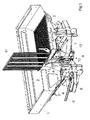
- the agricultural distributor is designed as a centrifugal fertilizer spreader. It has a storage container 1, which is divided by a roof-shaped Miteilteil 2 into two funnel-shaped outlet areas 3. The funnel-shaped outlet regions 3 are closed by metering elements. Below the metering 4 are rotatably driven centrifugal discs 5 with throwing blades 6. In the lower part of the discharge hopper 3 is located above the metering device 4 in the discharge funnel 3 projecting, rotatably mounted stirring shaft 7 with stirring elements 8. In order to better recognize and represent the arrangement of the stirring shaft 7 and arranged thereon stirring elements 8, the front wall of the reservoir 1 is not shown.
- the stirring shaft 7 is driven by a motor drive device, not shown, via a drive connection 9.
- the drive connection 9 is coupled via coupling elements 10 with the stirring shaft 7 in order to enable the stirring shaft 7 to rotate.
- the material in the reservoir 1 material is supplied to the centrifugal discs 5, through which it is distributed by the throwing blades 6 in wide distribution on the soil surface.
- a protective grid 11 protective devices are arranged, which during the Ausbringvorganges in the in Fig. 1 and 2 shown protection position and thus prevent access from the outside to the arranged in the lower part of the reservoir 1 stirring 8 and metering.
- this protective grid 11 so the stirring 8 and / or metering elements are shielded.
- the respective protective grid 11 and the coupling elements 10 of the drive connection 9 means are arranged which ensure that the protection device 11 formed as a protective device, when from its protective position according to Fig. 1 and 2 in the opening position according to Fig. 3 and 4 is moved, acting on the coupling elements of the drive connection, that the agitator shaft 7 and / or the stirring or dosing 8 are shut down by disconnecting from the drive device.
- the coupling element 10, between the drive connection. 9 and the stirring shaft 7 is arranged is designed as a wrap spring clutch.
- wrap spring clutch 10 instead of a wrap spring clutch 10, it is also possible in a manner not shown to use freewheels and then to be arranged between the protective grid 11 and the freewheels rods 13 so that these rods 13 act on the freewheels that the drive of the agitator shaft 7 via the Drive connection 9 is stopped.
Landscapes
- Life Sciences & Earth Sciences (AREA)
- Soil Sciences (AREA)
- Environmental Sciences (AREA)
- Fertilizing (AREA)
- Pretreatment Of Seeds And Plants (AREA)
- Catching Or Destruction (AREA)
Abstract
Description
- Die Erfindung betrifft eine landwirtschaftliche Verteilmaschine gemäß des Oberbegriffes des Patentanspruches 1.
- Eine derartige Verteilmaschine ist beispielsweise durch die
EP 08 57 409 B1 bekannt. Diese Verteilmaschine ist als Düngerstreuer ausgebildet und weist eine Schutzvorrichtung auf. Diese Schutzvorrichtung ist beabstandet zu den von den Wurfschaufeln beschriebenen Umlaufbahnen angeordnet. Durch diese Schutzvorrichtung soll verhindert werden, dass die Streuelemente in ungewünschter Weise berührt werden. Es ist in einer Ausgestaltung vorgesehen, dass die Kupplung der Antriebswelle gelöst wird, wenn die Schutzvorrichtung aus ihrer Schutzposition gebracht wird. Bei dieser bekannten Maschine ist es möglich, wenn die Schutzeinrichtung sich in ihrer Schutzposition befindet, trotzdem noch sich an der sich in dem Vorratsbehälter befindlichen angetriebenen Rühreinrichtung verletzen. - Durch
EP 17 67 981 A2 ist ein weiterer Düngerstreuer mit einem Vorratsbehälter und einer Schutzvorrichtung bekannt. Diese Schutzvorrichtung ist innerhalb des Vorratsbehälters angeordnet. Sie befindet sich oberhalb der dem Vorratsbehälter zugeordneten Rühr- und Dosierelemente. Der Schutzeinrichtung ist ein Verriegelungselement zugeordnet, welches nur mit einem zusätzlichen Betätigungselement aus seiner Schutzposition zu bringen ist. Eine Abschaltung der Dosier- und Rührorgane erfolgt hier jedoch nicht, wenn die Schutzvorrichtung aus ihrer Schutzposition gebracht wird. - Der Erfindung liegt die Aufgabe zugrunde, eine landwirtschaftliche Verteilmaschine vorzuschlagen, bei welcher ein wirksamer Schutz vor Verletzungen durch angetriebene Rühr- und Dosierelemente erreicht wird.
- Diese Aufgabe wird erfindungsgemäß dadurch gelöst, dass die dem Vorratsbehälter zugeordnete Schutzeinrichtung mit Mitteln ausgestattet ist, die bei Entfernen der Schutzeinrichtung aus ihrer Schutzposition auf die Antriebsvorrichtung derart einwirken, dass die Rühr- und/oder Dosierelemente durch Trennen, vorzugsweise durch Trennmittel von der Antriebsvorrichtung stillsetzbar sind. Infolge dieser Maßnahmen werden beim Entfernen der Schutzvorrichtung aus ihrer Schutzposition die Antriebsvorrichtungen der Rühr- und Dosierelemente sicher abgeschaltet. Hierdurch werden sicher Verletzungen durch die Dosier- und Rührvorrichtung, die im Vorratsbehälter zugeordnet ist, verhindert.
- Um diese Abschaltung sicher zu gewährleisten, ist vorgesehen, dass die Mittel eine der Antriebsvorrichtung zugeordnete Kupplungsvorrichtung aufweisen.
- In einer bevorzugten Ausführungsform ist vorgesehen, dass die Mittel als elektrischer Sensor und/oder Schalter ausgebildet sind, dass der Sensor und/oder Schalter mit der Kupplungsvorrichtung über Übertragungsmittel verbunden ist.
- Es ist jedoch auch möglich, den erfindungsgemäßen Schutz dadurch zu erreichen, dass die Mittel als mechanische Übertragungsmittel, die auf die Kupplungsvorrichtung bei Entfernen der Schutzvorrichtung aus der Schutzposition einwirken, ausgebildet sind.
- Weitere Einzelheiten der Erfindung sind der Beispielsbeschreibung und den Zeichnungen zu entnehmen. Hierbei zeigen
- Fig. 1
- die als Schleuderdüngerstreuer ausgebildete Verteilmaschine mit sich in Schließstellung befindlicher Schutzeinrichtung in perspektivischer Ansicht schräg von vorne oben und in Teildarstellung,
- Fig. 2
- den Abschaltbereich für die Rühreinrichtung bei geschlossener Schutzeinrichtung in vergrößertem Maßstab und Teildarstellung nach der Darstellungsweise gemäß
Fig. 1 , - Fig. 3
- die als Schleuderdüngerstreuer ausgebildete Verteilmaschine in perspektivischer Ansicht schräg von vorne oben in Teildarstellung, wobei die in Fahrtrichtung rechte Schutzeinrichtung innerhalb des Vorratsbehälters sich in Öffnungsstellung befindet und
- Fig. 4
- den Abschaltbereich für die Rühreinrichtung bei geöffneter rechter Schutzeinrichtung in vergrößertem Maßstab und Teilansicht nach der Darstellungsweise gemäß
Fig. 3 . - Die landwirtschaftliche Verteilmaschine ist als Schleuderdüngerstreuer ausgebildet. Sie weist einen Vorratsbehälter 1 auf, der durch ein dachförmiges Miteilteil 2 in zwei trichterförmige Auslaufbereiche 3 aufgeteilt ist. Die trichterförmigen Auslaufbereiche 3 werden durch Dosierelemente abgeschlossen. Unterhalb der Dosierelemente 4 befinden sich rotierend angetriebene Schleuderscheiben 5 mit Wurfschaufeln 6. Im unteren Bereich der Auslauftrichter 3 befindet sich oberhalb der Dosiereinrichtung 4 eine in die Auslauftrichter 3 hineinragende, drehbar gelagerte Rührwelle 7 mit Rührelementen 8. Um die Anordnung der Rührwelle 7 und die darauf angeordneten Rührelemente 8 besser erkennen und darstellen zu können, ist die Vorderwand des Vorratsbehälters 1 nicht dargestellt. Die Rührwelle 7 wird von einer nicht dargestellten motorischen Antriebsvorrichtung über eine Antriebsverbindung 9 angetrieben. Die Antriebsverbindung 9 wird über Kupplungselemente 10 mit der Rührwelle 7 gekoppelt, um die Rührwelle 7 in Rotation versetzen zu können.
- Über die Dosierorgane 4 wird das sich im Vorratsbehälter 1 befindliche Material den Schleuderscheiben 5 zugeführt, über welche es von den Wurfschaufeln 6 in Breitverteilung auf der Bodenoberfläche verteilt wird.
- Innerhalb des Vorratsbehälters 1 sind die als Schutzgitter 11 ausgebildeten Schutzeinrichtungen angeordnet, die während des Ausbringvorganges sich in der in
Fig. 1 und2 dargestellten Schutzposition befinden und somit den Zugang von außen zu den sich im unteren Bereich des Vorratsbehälters 1 angeordneten Rühr- 8 und Dosierelemente verhindern. Durch diese Schutzgitter 11 werden also die Rühr- 8 und/oder Dosierelemente abgeschirmt. - Zwischen dem jeweiligen Schutzgitter 11 und den Kupplungselementen 10 der Antriebsverbindung 9 sind Mittel angeordnet, die sicherstellen, dass die als Schutzgitter 11 ausgebildete Schutzeinrichtung, wenn sie aus ihrer Schutzposition gemäß
Fig. 1 und2 in die Öffnungsposition gemäßFig. 3 und4 bewegt wird, derart auf die Kupplungselemente der Antriebsverbindung einwirkt, dass die Rührwelle 7 und/oder die Rühr- oder Dosierelemente 8 durch trennen von der Antriebsvorrichtung still setzbar sind. Dies wird im Ausführungsbeispiel dadurch erreicht, dass das Kupplungselement 10, das zwischen der Antriebsverbindung 9 und der Rührwelle 7 angeordnet ist, ist als Schlingfederkupplung ausgebildet ist. An der Schlingfederkupplung 10 angreifend sind die zwischen den beiden Schutzgittern 11 und der Schlingfederkupplung 10 angeordneten Verbindungsstangen 13 der Mittel 12 zugeordnet, die bei dem Öffnen eines der Schutzgitter 11 derart auf die Schlingfederkupplung 13 einwirken, dass der Antrieb zwischen der Antriebsverbindung 9 und der Rührwelle 7 getrennt wird, so dass die Rührwelle 7 stillgesetzt wird. - Anstelle einer Schlingfederkupplung 10 ist es jedoch auch in nicht dargestellter Weise möglich, Freiläufe einzusetzen und dann die zwischen dem Schutzgitter 11 und den Freiläufen anzuordnenden Stangen 13 so auszubilden, dass diese Stangen 13 so auf die Freiläufe einwirken, dass der Antrieb der Rührwelle 7 über die Antriebsverbindung 9 still gesetzt wird.
- In einer anderen nicht dargestellten Ausgestaltung, ist es auch möglich, dass anstelle mechanischer Kupplungsmittel 10 elektrische Kupplungsmittel eingesetzt werden, um dann über elektrische Sensoren, Schalter, Kupplungsmittel etc. die Rühr- und/oder Dosierelemente 8 in geeigneter Weise stillsetzbar sind.
Claims (6)
- Landwirtschaftliche Verteilmaschine mit einem Vorratsbehälter, in dem über eine zumindest eine Abschalteinrichtung aufweisende Antriebsvorrichtung angetriebene Rühr- und/oder Dosierelemente angeordnet sind, wobei oberhalb der Rühr- und/oder Dosierelemente eine die Rühr- und/oder Dosierelemente abschirmende Schutzeinrichtung dem Vorratsbehälter zugeordnet ist, dadurch gekennzeichnet, dass die dem Vorratsbehälter ( 1 ) zugeordnete Schutzeinrichtung ( 11 ) mit Mitteln ( 12, 13 ) ausgestattet ist, die bei Entfernen der Schutzeinrichtung ( 11 ) aus ihrer Schutzposition auf die Antriebsvorrichtung ( 9 ) derart einwirken, dass die Rühr- und/oder Dosierelemente ( 4, 7, 8 ) durch Trennen, vorzugsweise durch Trennmittel ( 10 ) von der Antriebsvorrichtung ( 9 ) stillsetzbar sind.
- Verteilmaschine nach Anspruch 1, dadurch gekennzeichnet, dass die Mittel eine der Antriebsvorrichtung ( 9 ) zugeordnete Kupplungsvorrichtung ( 10 ) aufweisen.
- Verteilmaschine nach einem oder mehreren der vorstehenden Ansprüche, dadurch gekennzeichnet, dass die Mittel als elektrischer Sensor und/oder Schalter ausgebildet sind, dass der Sensor und/oder Schalter mit der Kupplungsvorrichtung über Übertragungsmittel verbunden ist.
- Verteilmaschine nach Anspruch 1, und/oder 2, dadurch gekennzeichnet, dass die Mittel ( 12 ) als mechanische Übertragungsmittel ( 13 ) , die auf die Kupplungsvorrichtung ( 10 ) bei Entfernen der Schutzvorrichtung ( 11 ) aus der Schutzposition einwirken, ausgebildet sind.
- Verteilmaschine nach Anspruch 2, dadurch gekennzeichnet, dass die Kupplungsvorrichtung als Schlingfederkupplung ( 10 ) ausgebildet ist.
- Verteilmaschine nach Anspruch 2, dadurch gekennzeichnet, dass die Kupplungsvorrichtung als einen auf einen Freilauf einwirkendes Mittel ausgebildet ist.
Priority Applications (1)
| Application Number | Priority Date | Filing Date | Title |
|---|---|---|---|
| PL10401030T PL2227934T3 (pl) | 2009-03-13 | 2010-03-11 | Rozsiewacz rolniczy |
Applications Claiming Priority (1)
| Application Number | Priority Date | Filing Date | Title |
|---|---|---|---|
| DE102009013178A DE102009013178A1 (de) | 2009-03-13 | 2009-03-13 | Landwirtschaftliche Verteilmaschine |
Publications (2)
| Publication Number | Publication Date |
|---|---|
| EP2227934A1 true EP2227934A1 (de) | 2010-09-15 |
| EP2227934B1 EP2227934B1 (de) | 2011-11-23 |
Family
ID=42340400
Family Applications (1)
| Application Number | Title | Priority Date | Filing Date |
|---|---|---|---|
| EP10401030A Not-in-force EP2227934B1 (de) | 2009-03-13 | 2010-03-11 | Landwirtschaftliche Verteilmaschine |
Country Status (4)
| Country | Link |
|---|---|
| EP (1) | EP2227934B1 (de) |
| AT (1) | ATE534278T1 (de) |
| DE (1) | DE102009013178A1 (de) |
| PL (1) | PL2227934T3 (de) |
Cited By (2)
| Publication number | Priority date | Publication date | Assignee | Title |
|---|---|---|---|---|
| EP2574224A1 (de) * | 2011-09-29 | 2013-04-03 | Amazonen-Werke H. Dreyer GmbH & Co. KG | Siebartige Abdeck- und Schutzeinrichtung |
| EP2653023A1 (de) * | 2012-04-20 | 2013-10-23 | Amazonen-Werke H. Dreyer GmbH & Co. KG | Behälter landwirtschaftlicher Verteilmaschinen |
Families Citing this family (2)
| Publication number | Priority date | Publication date | Assignee | Title |
|---|---|---|---|---|
| US11425915B2 (en) | 2018-05-02 | 2022-08-30 | Land O'lakes, Inc. | Methods of concentrating phospholipids |
| US12161131B2 (en) | 2018-12-20 | 2024-12-10 | Land O'lakes, Inc. | Cheese sauce |
Citations (4)
| Publication number | Priority date | Publication date | Assignee | Title |
|---|---|---|---|---|
| DE4309730A1 (de) * | 1993-03-25 | 1994-09-29 | Amazonen Werke Dreyer H | Verteilmaschine mit siebartiger Abdeckung für deren Vorratsbehälter |
| WO1998009890A1 (en) * | 1996-09-06 | 1998-03-12 | Agrex S.R.L. | A machine for spreading granular materials, particularly fertilizers |
| EP0857409A1 (de) * | 1997-02-11 | 1998-08-12 | Maasland N.V. | Düngerstreuer |
| DE202008013948U1 (de) * | 2008-10-18 | 2009-01-08 | Rauch Landmaschinenfabrik Gmbh | Landmaschine, insbesondere Verteilmaschine |
Family Cites Families (1)
| Publication number | Priority date | Publication date | Assignee | Title |
|---|---|---|---|---|
| US8362987B2 (en) | 2004-09-27 | 2013-01-29 | Qualcomm Mems Technologies, Inc. | Method and device for manipulating color in a display |
-
2009
- 2009-03-13 DE DE102009013178A patent/DE102009013178A1/de not_active Withdrawn
-
2010
- 2010-03-11 PL PL10401030T patent/PL2227934T3/pl unknown
- 2010-03-11 EP EP10401030A patent/EP2227934B1/de not_active Not-in-force
- 2010-03-11 AT AT10401030T patent/ATE534278T1/de active
Patent Citations (4)
| Publication number | Priority date | Publication date | Assignee | Title |
|---|---|---|---|---|
| DE4309730A1 (de) * | 1993-03-25 | 1994-09-29 | Amazonen Werke Dreyer H | Verteilmaschine mit siebartiger Abdeckung für deren Vorratsbehälter |
| WO1998009890A1 (en) * | 1996-09-06 | 1998-03-12 | Agrex S.R.L. | A machine for spreading granular materials, particularly fertilizers |
| EP0857409A1 (de) * | 1997-02-11 | 1998-08-12 | Maasland N.V. | Düngerstreuer |
| DE202008013948U1 (de) * | 2008-10-18 | 2009-01-08 | Rauch Landmaschinenfabrik Gmbh | Landmaschine, insbesondere Verteilmaschine |
Cited By (2)
| Publication number | Priority date | Publication date | Assignee | Title |
|---|---|---|---|---|
| EP2574224A1 (de) * | 2011-09-29 | 2013-04-03 | Amazonen-Werke H. Dreyer GmbH & Co. KG | Siebartige Abdeck- und Schutzeinrichtung |
| EP2653023A1 (de) * | 2012-04-20 | 2013-10-23 | Amazonen-Werke H. Dreyer GmbH & Co. KG | Behälter landwirtschaftlicher Verteilmaschinen |
Also Published As
| Publication number | Publication date |
|---|---|
| PL2227934T3 (pl) | 2012-04-30 |
| ATE534278T1 (de) | 2011-12-15 |
| EP2227934B1 (de) | 2011-11-23 |
| DE102009013178A1 (de) | 2010-09-16 |
Similar Documents
| Publication | Publication Date | Title |
|---|---|---|
| EP2227934B1 (de) | Landwirtschaftliche Verteilmaschine | |
| EP2358473A1 (de) | Vorrichtung zum zerkleinern und aufschliessen | |
| AT509612A1 (de) | Vorrichtung zum verarbeiten von garten-, erdgut und dergleichen | |
| EP1570716A2 (de) | Landwirtschaftliche Dossiervorrichtung | |
| DE19751368A1 (de) | Anbauhäcksler eines Mähdreschers | |
| EP3127416B1 (de) | Schneckenverteiler | |
| DE202006007543U1 (de) | Kugelmühle mit Gehäuse und Gehäusedeckel | |
| DE3925581A1 (de) | Zerkleinerungsmaschine | |
| EP0813944A2 (de) | Feststoffmühle | |
| DE3824888C2 (de) | ||
| EP2742788B1 (de) | Streugerät | |
| DE3527023C2 (de) | ||
| DE4431173A1 (de) | Abfallzerkleinerungsvorrichtung | |
| EP1078564B1 (de) | Schleuderdüngerstreuer | |
| EP2574224B1 (de) | Vorratsbehälter mit einer siebartigen Abdeck- und Schutzeinrichtung | |
| EP2183953B1 (de) | Scheibendüngerstreuer | |
| DE10300086B4 (de) | Zerkleinerungsvorrichtung mit Flügelrad | |
| DE19929999C2 (de) | Vorrichtung zum Zerkleinern von häcksel- und schnitzelfähigem Gut | |
| EP0439718B1 (de) | Schleuderdüngerstreuer | |
| EP2227933A1 (de) | Verteilmaschine | |
| DE102006041083A1 (de) | Schleuderdüngerstreuer | |
| DE2925516C2 (de) | Vorrichtung zum Zerkleinern verpackten Brotes zu Futterzwecken | |
| DE102010036791A1 (de) | Schleuderstreuer | |
| DE9308345U1 (de) | Zerkleinerungs- und Siebgerät | |
| DE2917068A1 (de) | Einwalzenbrecher |
Legal Events
| Date | Code | Title | Description |
|---|---|---|---|
| PUAI | Public reference made under article 153(3) epc to a published international application that has entered the european phase |
Free format text: ORIGINAL CODE: 0009012 |
|
| AK | Designated contracting states |
Kind code of ref document: A1 Designated state(s): AT BE BG CH CY CZ DE DK EE ES FI FR GB GR HR HU IE IS IT LI LT LU LV MC MK MT NL NO PL PT RO SE SI SK SM TR |
|
| AX | Request for extension of the european patent |
Extension state: AL BA ME RS |
|
| 17P | Request for examination filed |
Effective date: 20101022 |
|
| RIC1 | Information provided on ipc code assigned before grant |
Ipc: A01C 15/00 20060101AFI20101223BHEP |
|
| GRAP | Despatch of communication of intention to grant a patent |
Free format text: ORIGINAL CODE: EPIDOSNIGR1 |
|
| GRAS | Grant fee paid |
Free format text: ORIGINAL CODE: EPIDOSNIGR3 |
|
| GRAA | (expected) grant |
Free format text: ORIGINAL CODE: 0009210 |
|
| AK | Designated contracting states |
Kind code of ref document: B1 Designated state(s): AT BE BG CH CY CZ DE DK EE ES FI FR GB GR HR HU IE IS IT LI LT LU LV MC MK MT NL NO PL PT RO SE SI SK SM TR |
|
| REG | Reference to a national code |
Ref country code: GB Ref legal event code: FG4D Free format text: NOT ENGLISH |
|
| REG | Reference to a national code |
Ref country code: CH Ref legal event code: EP |
|
| REG | Reference to a national code |
Ref country code: IE Ref legal event code: FG4D Free format text: LANGUAGE OF EP DOCUMENT: GERMAN |
|
| REG | Reference to a national code |
Ref country code: DE Ref legal event code: R096 Ref document number: 502010000245 Country of ref document: DE Effective date: 20120209 |
|
| REG | Reference to a national code |
Ref country code: NL Ref legal event code: VDEP Effective date: 20111123 |
|
| LTIE | Lt: invalidation of european patent or patent extension |
Effective date: 20111123 |
|
| PG25 | Lapsed in a contracting state [announced via postgrant information from national office to epo] |
Ref country code: LT Free format text: LAPSE BECAUSE OF FAILURE TO SUBMIT A TRANSLATION OF THE DESCRIPTION OR TO PAY THE FEE WITHIN THE PRESCRIBED TIME-LIMIT Effective date: 20111123 Ref country code: IS Free format text: LAPSE BECAUSE OF FAILURE TO SUBMIT A TRANSLATION OF THE DESCRIPTION OR TO PAY THE FEE WITHIN THE PRESCRIBED TIME-LIMIT Effective date: 20120323 Ref country code: NO Free format text: LAPSE BECAUSE OF FAILURE TO SUBMIT A TRANSLATION OF THE DESCRIPTION OR TO PAY THE FEE WITHIN THE PRESCRIBED TIME-LIMIT Effective date: 20120223 |
|
| REG | Reference to a national code |
Ref country code: PL Ref legal event code: T3 |
|
| PG25 | Lapsed in a contracting state [announced via postgrant information from national office to epo] |
Ref country code: SE Free format text: LAPSE BECAUSE OF FAILURE TO SUBMIT A TRANSLATION OF THE DESCRIPTION OR TO PAY THE FEE WITHIN THE PRESCRIBED TIME-LIMIT Effective date: 20111123 Ref country code: PT Free format text: LAPSE BECAUSE OF FAILURE TO SUBMIT A TRANSLATION OF THE DESCRIPTION OR TO PAY THE FEE WITHIN THE PRESCRIBED TIME-LIMIT Effective date: 20120323 Ref country code: LV Free format text: LAPSE BECAUSE OF FAILURE TO SUBMIT A TRANSLATION OF THE DESCRIPTION OR TO PAY THE FEE WITHIN THE PRESCRIBED TIME-LIMIT Effective date: 20111123 Ref country code: HR Free format text: LAPSE BECAUSE OF FAILURE TO SUBMIT A TRANSLATION OF THE DESCRIPTION OR TO PAY THE FEE WITHIN THE PRESCRIBED TIME-LIMIT Effective date: 20111123 Ref country code: SI Free format text: LAPSE BECAUSE OF FAILURE TO SUBMIT A TRANSLATION OF THE DESCRIPTION OR TO PAY THE FEE WITHIN THE PRESCRIBED TIME-LIMIT Effective date: 20111123 Ref country code: NL Free format text: LAPSE BECAUSE OF FAILURE TO SUBMIT A TRANSLATION OF THE DESCRIPTION OR TO PAY THE FEE WITHIN THE PRESCRIBED TIME-LIMIT Effective date: 20111123 Ref country code: GR Free format text: LAPSE BECAUSE OF FAILURE TO SUBMIT A TRANSLATION OF THE DESCRIPTION OR TO PAY THE FEE WITHIN THE PRESCRIBED TIME-LIMIT Effective date: 20120224 |
|
| REG | Reference to a national code |
Ref country code: IE Ref legal event code: FD4D |
|
| PG25 | Lapsed in a contracting state [announced via postgrant information from national office to epo] |
Ref country code: CY Free format text: LAPSE BECAUSE OF FAILURE TO SUBMIT A TRANSLATION OF THE DESCRIPTION OR TO PAY THE FEE WITHIN THE PRESCRIBED TIME-LIMIT Effective date: 20111123 |
|
| PG25 | Lapsed in a contracting state [announced via postgrant information from national office to epo] |
Ref country code: BG Free format text: LAPSE BECAUSE OF FAILURE TO SUBMIT A TRANSLATION OF THE DESCRIPTION OR TO PAY THE FEE WITHIN THE PRESCRIBED TIME-LIMIT Effective date: 20120223 Ref country code: DK Free format text: LAPSE BECAUSE OF FAILURE TO SUBMIT A TRANSLATION OF THE DESCRIPTION OR TO PAY THE FEE WITHIN THE PRESCRIBED TIME-LIMIT Effective date: 20111123 Ref country code: EE Free format text: LAPSE BECAUSE OF FAILURE TO SUBMIT A TRANSLATION OF THE DESCRIPTION OR TO PAY THE FEE WITHIN THE PRESCRIBED TIME-LIMIT Effective date: 20111123 Ref country code: CZ Free format text: LAPSE BECAUSE OF FAILURE TO SUBMIT A TRANSLATION OF THE DESCRIPTION OR TO PAY THE FEE WITHIN THE PRESCRIBED TIME-LIMIT Effective date: 20111123 Ref country code: IE Free format text: LAPSE BECAUSE OF FAILURE TO SUBMIT A TRANSLATION OF THE DESCRIPTION OR TO PAY THE FEE WITHIN THE PRESCRIBED TIME-LIMIT Effective date: 20111123 Ref country code: SK Free format text: LAPSE BECAUSE OF FAILURE TO SUBMIT A TRANSLATION OF THE DESCRIPTION OR TO PAY THE FEE WITHIN THE PRESCRIBED TIME-LIMIT Effective date: 20111123 |
|
| PG25 | Lapsed in a contracting state [announced via postgrant information from national office to epo] |
Ref country code: IT Free format text: LAPSE BECAUSE OF FAILURE TO SUBMIT A TRANSLATION OF THE DESCRIPTION OR TO PAY THE FEE WITHIN THE PRESCRIBED TIME-LIMIT Effective date: 20111123 Ref country code: RO Free format text: LAPSE BECAUSE OF FAILURE TO SUBMIT A TRANSLATION OF THE DESCRIPTION OR TO PAY THE FEE WITHIN THE PRESCRIBED TIME-LIMIT Effective date: 20111123 |
|
| PLBE | No opposition filed within time limit |
Free format text: ORIGINAL CODE: 0009261 |
|
| STAA | Information on the status of an ep patent application or granted ep patent |
Free format text: STATUS: NO OPPOSITION FILED WITHIN TIME LIMIT |
|
| BERE | Be: lapsed |
Owner name: AMAZONEN-WERKE H. DREYER G.M.B.H. & CO. KG Effective date: 20120331 |
|
| 26N | No opposition filed |
Effective date: 20120824 |
|
| PG25 | Lapsed in a contracting state [announced via postgrant information from national office to epo] |
Ref country code: MC Free format text: LAPSE BECAUSE OF NON-PAYMENT OF DUE FEES Effective date: 20120331 |
|
| REG | Reference to a national code |
Ref country code: DE Ref legal event code: R097 Ref document number: 502010000245 Country of ref document: DE Effective date: 20120824 |
|
| PG25 | Lapsed in a contracting state [announced via postgrant information from national office to epo] |
Ref country code: BE Free format text: LAPSE BECAUSE OF NON-PAYMENT OF DUE FEES Effective date: 20120331 |
|
| PG25 | Lapsed in a contracting state [announced via postgrant information from national office to epo] |
Ref country code: MK Free format text: LAPSE BECAUSE OF FAILURE TO SUBMIT A TRANSLATION OF THE DESCRIPTION OR TO PAY THE FEE WITHIN THE PRESCRIBED TIME-LIMIT Effective date: 20111123 |
|
| PG25 | Lapsed in a contracting state [announced via postgrant information from national office to epo] |
Ref country code: ES Free format text: LAPSE BECAUSE OF FAILURE TO SUBMIT A TRANSLATION OF THE DESCRIPTION OR TO PAY THE FEE WITHIN THE PRESCRIBED TIME-LIMIT Effective date: 20120305 |
|
| PG25 | Lapsed in a contracting state [announced via postgrant information from national office to epo] |
Ref country code: FI Free format text: LAPSE BECAUSE OF FAILURE TO SUBMIT A TRANSLATION OF THE DESCRIPTION OR TO PAY THE FEE WITHIN THE PRESCRIBED TIME-LIMIT Effective date: 20111123 |
|
| PG25 | Lapsed in a contracting state [announced via postgrant information from national office to epo] |
Ref country code: MT Free format text: LAPSE BECAUSE OF FAILURE TO SUBMIT A TRANSLATION OF THE DESCRIPTION OR TO PAY THE FEE WITHIN THE PRESCRIBED TIME-LIMIT Effective date: 20111123 |
|
| PG25 | Lapsed in a contracting state [announced via postgrant information from national office to epo] |
Ref country code: TR Free format text: LAPSE BECAUSE OF FAILURE TO SUBMIT A TRANSLATION OF THE DESCRIPTION OR TO PAY THE FEE WITHIN THE PRESCRIBED TIME-LIMIT Effective date: 20111123 |
|
| PG25 | Lapsed in a contracting state [announced via postgrant information from national office to epo] |
Ref country code: LU Free format text: LAPSE BECAUSE OF NON-PAYMENT OF DUE FEES Effective date: 20120311 Ref country code: SM Free format text: LAPSE BECAUSE OF FAILURE TO SUBMIT A TRANSLATION OF THE DESCRIPTION OR TO PAY THE FEE WITHIN THE PRESCRIBED TIME-LIMIT Effective date: 20111123 |
|
| PG25 | Lapsed in a contracting state [announced via postgrant information from national office to epo] |
Ref country code: HU Free format text: LAPSE BECAUSE OF FAILURE TO SUBMIT A TRANSLATION OF THE DESCRIPTION OR TO PAY THE FEE WITHIN THE PRESCRIBED TIME-LIMIT Effective date: 20100311 |
|
| REG | Reference to a national code |
Ref country code: CH Ref legal event code: PL |
|
| GBPC | Gb: european patent ceased through non-payment of renewal fee |
Effective date: 20140311 |
|
| PG25 | Lapsed in a contracting state [announced via postgrant information from national office to epo] |
Ref country code: LI Free format text: LAPSE BECAUSE OF NON-PAYMENT OF DUE FEES Effective date: 20140331 Ref country code: GB Free format text: LAPSE BECAUSE OF NON-PAYMENT OF DUE FEES Effective date: 20140311 Ref country code: CH Free format text: LAPSE BECAUSE OF NON-PAYMENT OF DUE FEES Effective date: 20140331 |
|
| REG | Reference to a national code |
Ref country code: FR Ref legal event code: PLFP Year of fee payment: 7 |
|
| PGFP | Annual fee paid to national office [announced via postgrant information from national office to epo] |
Ref country code: DE Payment date: 20160308 Year of fee payment: 7 |
|
| REG | Reference to a national code |
Ref country code: AT Ref legal event code: MM01 Ref document number: 534278 Country of ref document: AT Kind code of ref document: T Effective date: 20150311 |
|
| PGFP | Annual fee paid to national office [announced via postgrant information from national office to epo] |
Ref country code: FR Payment date: 20160208 Year of fee payment: 7 Ref country code: PL Payment date: 20160112 Year of fee payment: 7 |
|
| PG25 | Lapsed in a contracting state [announced via postgrant information from national office to epo] |
Ref country code: AT Free format text: LAPSE BECAUSE OF NON-PAYMENT OF DUE FEES Effective date: 20150311 |
|
| REG | Reference to a national code |
Ref country code: DE Ref legal event code: R119 Ref document number: 502010000245 Country of ref document: DE |
|
| REG | Reference to a national code |
Ref country code: FR Ref legal event code: ST Effective date: 20171130 |
|
| PG25 | Lapsed in a contracting state [announced via postgrant information from national office to epo] |
Ref country code: DE Free format text: LAPSE BECAUSE OF NON-PAYMENT OF DUE FEES Effective date: 20171003 Ref country code: FR Free format text: LAPSE BECAUSE OF NON-PAYMENT OF DUE FEES Effective date: 20170331 |
|
| PG25 | Lapsed in a contracting state [announced via postgrant information from national office to epo] |
Ref country code: PL Free format text: LAPSE BECAUSE OF NON-PAYMENT OF DUE FEES Effective date: 20170311 |