EP2227070A2 - Zündgerät für eine Hochdruckgasentladungslampe - Google Patents
Zündgerät für eine Hochdruckgasentladungslampe Download PDFInfo
- Publication number
- EP2227070A2 EP2227070A2 EP10155119A EP10155119A EP2227070A2 EP 2227070 A2 EP2227070 A2 EP 2227070A2 EP 10155119 A EP10155119 A EP 10155119A EP 10155119 A EP10155119 A EP 10155119A EP 2227070 A2 EP2227070 A2 EP 2227070A2
- Authority
- EP
- European Patent Office
- Prior art keywords
- contact
- housing
- contact wire
- indentation
- gas discharge
- Prior art date
- Legal status (The legal status is an assumption and is not a legal conclusion. Google has not performed a legal analysis and makes no representation as to the accuracy of the status listed.)
- Withdrawn
Links
- 238000004804 winding Methods 0.000 claims abstract description 14
- 238000007373 indentation Methods 0.000 claims description 11
- PXHVJJICTQNCMI-UHFFFAOYSA-N Nickel Chemical compound [Ni] PXHVJJICTQNCMI-UHFFFAOYSA-N 0.000 claims description 4
- 239000000463 material Substances 0.000 claims description 3
- 229910052759 nickel Inorganic materials 0.000 claims description 2
- 229910052799 carbon Inorganic materials 0.000 description 4
- OKTJSMMVPCPJKN-UHFFFAOYSA-N Carbon Chemical compound [C] OKTJSMMVPCPJKN-UHFFFAOYSA-N 0.000 description 3
- 238000003466 welding Methods 0.000 description 3
- 238000005452 bending Methods 0.000 description 2
- 230000015572 biosynthetic process Effects 0.000 description 2
- 238000009434 installation Methods 0.000 description 2
- 238000004519 manufacturing process Methods 0.000 description 2
- 230000006978 adaptation Effects 0.000 description 1
- 150000001721 carbon Chemical class 0.000 description 1
- 150000001875 compounds Chemical class 0.000 description 1
- 238000003780 insertion Methods 0.000 description 1
- 230000037431 insertion Effects 0.000 description 1
- 239000000696 magnetic material Substances 0.000 description 1
- 239000002184 metal Substances 0.000 description 1
- 229910052751 metal Inorganic materials 0.000 description 1
- 239000012811 non-conductive material Substances 0.000 description 1
- 238000004382 potting Methods 0.000 description 1
- 230000005855 radiation Effects 0.000 description 1
- 229910052724 xenon Inorganic materials 0.000 description 1
- FHNFHKCVQCLJFQ-UHFFFAOYSA-N xenon atom Chemical compound [Xe] FHNFHKCVQCLJFQ-UHFFFAOYSA-N 0.000 description 1
- 229910000859 α-Fe Inorganic materials 0.000 description 1
Images

Classifications
-
- H—ELECTRICITY
- H05—ELECTRIC TECHNIQUES NOT OTHERWISE PROVIDED FOR
- H05B—ELECTRIC HEATING; ELECTRIC LIGHT SOURCES NOT OTHERWISE PROVIDED FOR; CIRCUIT ARRANGEMENTS FOR ELECTRIC LIGHT SOURCES, IN GENERAL
- H05B41/00—Circuit arrangements or apparatus for igniting or operating discharge lamps
- H05B41/02—Details
- H05B41/04—Starting switches
-
- Y—GENERAL TAGGING OF NEW TECHNOLOGICAL DEVELOPMENTS; GENERAL TAGGING OF CROSS-SECTIONAL TECHNOLOGIES SPANNING OVER SEVERAL SECTIONS OF THE IPC; TECHNICAL SUBJECTS COVERED BY FORMER USPC CROSS-REFERENCE ART COLLECTIONS [XRACs] AND DIGESTS
- Y02—TECHNOLOGIES OR APPLICATIONS FOR MITIGATION OR ADAPTATION AGAINST CLIMATE CHANGE
- Y02B—CLIMATE CHANGE MITIGATION TECHNOLOGIES RELATED TO BUILDINGS, e.g. HOUSING, HOUSE APPLIANCES OR RELATED END-USER APPLICATIONS
- Y02B20/00—Energy efficient lighting technologies, e.g. halogen lamps or gas discharge lamps
Definitions
- the invention relates to an ignition device for a high-pressure gas discharge lamp according to the preamble of claim 1.
- high-pressure gas discharge lamps such as e.g. Xenon lamps used. These lamps require for starting a high ignition voltage of several kV, which is generated as a voltage pulse in an ignitor.
- ignitors include a housing in which an ignition transformer and a printed circuit board with electrical / electronic components and circuits are mounted. The ignitor is usually preceded by a ballast.
- Such ignitors are known per se.
- the insertion of the ignition transformer according to the prior art is relatively expensive.
- the material of the housing is decomposed, whereby free carbon is formed. This carbon can lead to flashovers of high voltage during operation of the ignitor.
- the DE 103 39 587 A1 describes a lamp cap with an ignition transformer for a high-pressure gas discharge lamp.
- the ignition transformer comprises a housing which encloses at least one winding. For installation in the correct position of the transformer in the lamp base of the ignition transformer is provided on its outside with webs.
- the lamp base has corresponding grooves and prudence.
- the ignition transformer should be suitable in this way for automatic installation in the lamp base and for automated contacting. This contact is not described in detail.
- An ignition device is known with an ignition transformer for a high-pressure gas discharge lamp, in which a secondary winding is formed by a metal strip. This is arranged on an annular ferrite core, that a high voltage leading end of the secondary winding is disposed inside. In this way, the ignition transformer is to be improved. Automated production is difficult and time-consuming.
- the object of the invention is to provide an ignition device for a high-pressure gas discharge lamp, in which an ignition transformer can be easily attached and contacted in a housing without the risk of the formation of free carbon.
- An intended for the connection end of the first contact plate has a funnel-shaped indentation in the view and the contact wire is plastically bendable in the indentation.
- the contact wire is centered by the shape of the recess itself.
- the contact wire after bending at least two points of its circumference direct contact with the first contact plate.
- Laser welding can take place at these points without jets striking the housing.
- the ignition transformer is mounted in the housing and contacted, without any risk of the formation of free carbon. This safely prevents flashovers of high voltage during operation and increases the operational safety and service life of the ignitor.
- the automated production of the ignitor is facilitated overall.
- a smallest width of the indentation corresponds to a cross section of the contact wire. This causes an increase in the contact area between the contact wire and the first contact plate and thus a better attachment and a lower electrical resistance.
- the smallest width of the indentation is additionally undercut; this means that the smallest width still has a small constriction. As a result, the contact wire is held without further attachment in the recess.
- a cross section of the contact wire is round and an inner end of the indentation is semicircular.
- the contact wire is made of a nickel base material, it can be bent with otherwise sufficient stability simply and remains in the bent position.
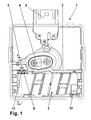
- an igniter for a high-pressure gas discharge lamp obviously comprises a cuboidal housing 1, an ignition transformer 2 and a printed circuit board, not shown.
- the housing 1 is made of an electrically non-conductive material such as plastic, transversely divided by a wall 3 and closed by means of a lid, not shown.
- the ignition transformer 2 is mounted in a first, after the FIG. 1 lower part of the housing 1, the ignition transformer 2 is mounted. In the other part protrude electrical and / or electronic components mounted on the circuit board are.
- a lamp base 4 is arranged in the other part.
- the circuit board is mounted parallel to the main surfaces of the housing 1 in this.
- a plug 5 is formed on the housing 1, which is contacted with the circuit board.
- the ignition transformer 2 a transformer housing 6, in which a core 7 of soft magnetic material and a secondary winding 8 are mounted. With a high voltage in operation leading first end of the secondary winding 8, a first contact plate 9 is connected, which is fixed to a corresponding end of the transformer housing 6. A second end of the secondary winding is connected to a second contact plate 10. To the transformer housing 6, a primary winding 11 is wound.
- the first contact plate 9 points at one after the FIGS. 2 and 3 upper end, which is the connection with the secondary winding 8 opposite, a funnel-shaped recess 12. This is open to a narrow side of the first contact plate 9 and has rounded lateral flanks and a semicircular inner end. In the area of the inner end, the indentation 12 is undercut.
- the first contact plate 9 is bent between the attachment to the transformer housing 6 and the recess 12 by about 30 ° from the transformer housing 6 away.
- a contact wire 13 is fixed so that it leads from the lamp cap 4 in the first part of the housing 1 and initially projects perpendicular to a bottom of the housing 1 in the first part.
- the contact wire 13 ends at a point which is located in the region of the first contact sheet 9 when the ignition transformer 2 is inserted.
- a longitudinal axis of the first contact plate 9 and a longitudinal axis of the contact wire 13 protruding into the first part are located on a perpendicular to a longitudinal axis of the ignition transformer 2.
- the ignition transformer 2 is inserted into the housing 1.
- the contact wire 13 is bent into the recess 12 so that it is held by the undercut and the first contact plate 9 as far as possible touched.
- the contact wire 13 is laser-welded attached to the first contact plate 9.
- the ignition transformer 2 and partially the first part of the housing 1 are filled with potting compound.
- the printed circuit board is placed and fastened on the housing 1. In this case, corresponding contact surfaces of the printed circuit board are in contact with end regions of the primary winding and on the second contact sheet 10.
- the end regions and the second contact plate 10 form further electrical connections of the ignition transformer 2.
- the contact surfaces on the one hand and the end regions of the primary winding and the second contact plate on the other hand are connected to one another by means of laser welding.
- the housing 1 is closed with the lid.
Landscapes
- Lighting Device Outwards From Vehicle And Optical Signal (AREA)
- Ignition Installations For Internal Combustion Engines (AREA)
- Non-Portable Lighting Devices Or Systems Thereof (AREA)
Abstract
Description
- Die Erfindung betrifft ein Zündgerät für eine Hochdruckgasentladungslampe gemäß dem Oberbegriff des Anspruchs 1.
- In Kraftfahrzeugen werden für Frontscheinwerfer wegen der besseren Lichtausbeute vermehrt Hochdruckgasentladungslampen wie z.B. Xenonlampen eingesetzt. Diese Lampen benötigen zum Starten eine hohe Zündspannung von mehreren kV, die als Spannungsimpuls in einem Zündgerät erzeugt wird. Diese Zündgeräte umfassen ein Gehäuse, in dem ein Zündtransformator und eine Leiterplatte mit elektrischen/ elektronischen Bauteilen und Schaltungen befestigt sind. Dem Zündgerät ist gewöhnlich ein Vorschaltgerät vorgeschaltet.
- Solche Zündgeräte sind an sich bekannt. Das Einsetzen des Zündtransformators nach dem Stand der Technik ist relativ aufwändig. Insbesondere gelangt beim Verschweißen eines Hochspannung führenden ersten Kontaktblechs mit einem Kontaktdraht zu einem Lampensockel mittels Laser ein Teil der Laserstrahlung an das Gehäuse. Hierdurch wird das Material des Gehäuses zersetzt, wodurch sich freier Kohlenstoff bildet. Dieser Kohlenstoff kann beim Betrieb des Zündgeräts zu Überschlägen von Hochspannung führen.
- Die
DE 103 39 587 A1 beschreibt einen Lampensockel mit einem Zündtransformator für eine Hochdruckgasentladungslampe. Der Zündtransformator umfasst ein Gehäuse, das mindestens eine Wicklung umschließt. Zum lagerichtigen Einbau des Transformators in den Lampensockel ist der Zündtransformator an seiner Außenseite mit Stegen versehen. Der Lampensockel weist entsprechende Nuten sowie Anstandhalter auf. Der Zündtransformator soll auf diese Weise für einen automatischen Einbau in den Lampensockel und für eine automatisierte Kontaktierung geeignet sein. Diese Kontaktierung ist nicht näher beschrieben. - Aus der
DE 10 2004 044 368 A1 ist eine Zündvorrichtung mit einem Zündtransformator für eine Hochdruckgasentladungslampe bekannt, bei dem eine Sekundärwicklung von einem Metallband gebildet ist. Dieses ist so auf einem ringförmigen Ferritkern angeordnet, dass ein Hochspannung führendes Ende der Sekundärwicklung innen liegend angeordnet ist. Auf diese Weise soll der Zündtransformator verbessert werden. Eine automatisierte Fertigung ist schwierig und aufwändig. - In der
DE 20 2005 007 484 U1 ist ein Zündtransformator für eine Gasentladungsleuchte mit einem offenen, nicht geradlinigen magnetischen Kern und einem Spulenkörper offenbart, der auf dem Kern aufgebracht ist und mehrere Kammern zur Aufnahme einer Sekundärwicklung aufweist. Auf diese Weise soll bei kompakter Bauweise die Flexibilität bei der Auslegung des Zündtransformators erzielt werden. Der Zündtransformator ist aufwändig und nur schwer automatisch zu fertigen. - Aufgabe der Erfindung ist es, ein Zündgerät für eine Hochdruckgasentladungslampe zu schaffen, bei dem ein Zündtransformator einfach und ohne Gefahr der Entstehung von freiem Kohlenstoff in einem Gehäuse befestigt und kontaktiert werden kann.
- Die Aufgabe ist durch die Merkmale des Anspruchs 1 gelöst. Ein für die Verbindung bestimmtes Ende des ersten Kontaktblechs weist eine in der Ansicht trichterförmige Einbuchtung auf und der Kontaktdraht ist in die Einbuchtung plastisch biegbar. Beim Biegen zentriert sich der Kontaktdraht durch die Form der Einbuchtung selbst. Hierdurch weist der Kontaktdraht nach dem Biegen an mindestens zwei Stellen seines Umfangs direkten Kontakt mit dem ersten Kontaktblech auf. An diesen Stellen kann ein Verschweißen mittels Laser erfolgen, ohne dass Strahlen auf das Gehäuse treffen. Auf diese Weise wird der Zündtransformator in dem Gehäuse befestigt und kontaktiert, ohne dass eine Gefahr der Entstehung von freiem Kohlenstoff besteht. Damit werden im Betrieb Überschläge von Hochspannung sicher vermieden und die Betriebssicherheit und Lebensdauer des Zündgeräts erhöht. Die automatisierte Fertigung des Zündgeräts wird insgesamt erleichtert.
- Die Unteransprüche betreffen die vorteilhafte Ausgestaltung der Erfindung.
- In einer Alternative entspricht eine kleinste Weite der Einbuchtung einem Querschnitt des Kontaktdrahts. Dies bewirkt eine Vergrößerung der Kontaktfläche zwischen dem Kontaktdraht und dem ersten Kontaktblech und somit eine bessere Befestigung und einen geringeren elektrischen Widerstand.
- Besonders vorteilhaft ist es, wenn die kleinste Weite der Einbuchtung zusätzlich hinterschnitten ist; das bedeutet, dass die kleinste Weite noch eine kleine Einschnürung aufweist. Hierdurch wird der Kontaktdraht auch ohne weitere Befestigung in der Einbuchtung gehalten.
- In eine weiteren Alternative ist ein Querschnitt des Kontaktdrahts rund und ein inneres Ende der Einbuchtung halbkreisförmig ausgebildet. Hierbei ist eine Anpassung der Formen besonders einfach und somit die Gefahr des Auftreffens von Laserstrahlen auf das Gehäuse stark reduziert.
- Wenn gemäß einer weiteren Ausbildung der Kontaktdraht aus einem Nickelgrundwerkstoff gefertigt ist, lässt er sich bei ansonsten ausreichender Stabilität einfach umbiegen und verbleibt in der gebogenen Position.
- Anhand der schematischen Zeichnung wird die Erfindung nachfolgend näher erläutert. Dabei zeigt:
-
Figur 1 eine Draufsicht auf ein Zündgerät mit eingesetztem Zündtransformator, -
Figur 2 einen Schnitt A - A gemäß derFigur 1 und -
Figur 3 eine perspektivische Ansicht des Zündtransformators als Detail. - Wie aus der
Figur 1 ersichtlich umfasst ein Zündgerät für eine Hochdruckgasentladungslampe ein quaderförmiges Gehäuse 1, einen Zündtransformator 2 und eine nicht dargestellte Leiterplatte. Das Gehäuse 1 ist aus einem elektrisch nicht leitenden Material wie z.B. Kunststoff gefertigt, mittels einer Wand 3 quergeteilt und mittels eines nicht dargestellten Deckels verschlossen. In einem ersten, nach derFigur 1 unteren Teil des Gehäuses 1 ist der Zündtransformator 2 gelagert. In den anderen Teil ragen elektrische und/oder elektronische Bauteile, die auf der Leiterplatte befestigt sind. Weiterhin ist in dem anderen Teil ein Lampensockel 4 angeordnet. Die Leiterplatte ist parallel zu den Hauptflächen des Gehäuses 1 in diesem gelagert. Für einen elektrischen Anschluss des Zündgeräts ist an dem Gehäuse 1 ein Stecker 5 ausgebildet, der mit der Leiterplatte kontaktiert ist. - Wie aus den
Figuren 2 und 3 deutlich wird, weist der Zündtransformator 2 ein Transformatorgehäuse 6 auf, in dem ein Kern 7 aus weichmagnetischem Material und eine Sekundärwicklung 8 gelagert sind. Mit einem im Betrieb Hochspannung führenden ersten Ende der Sekundärwicklung 8 ist ein erstes Kontaktblech 9 verbunden, das an einem entsprechenden Ende des Transformatorgehäuses 6 befestigt ist. Ein zweites Ende der Sekundärwicklung ist mit einem zweiten Kontaktblech 10 verbunden. Um das Transformatorgehäuse 6 ist eine Primärwicklung 11 gewickelt. - Das erste Kontaktblech 9 weist an einem nach den
Figuren 2 und 3 oberen Ende, das der Verbindung mit der Sekundärwicklung 8 gegenüber liegt, eine trichterförmige Einbuchtung 12 auf. Diese ist zu einer Schmalseite des ersten Kontaktblechs 9 offen und weist gerundete seitliche Flanken sowie ein halbkreisförmiges inneres Ende auf. Im Bereich des inneren Endes ist die Einbuchtung 12 hinterschnitten. Das erste Kontaktblech 9 ist zwischen der Befestigung an dem Transformatorgehäuses 6 und der Einbuchtung 12 um circa 30° von dem Transformatorgehäuses 6 weg umgebogen. - In dem Gehäuse 1 ist ein Kontaktdraht 13 so befestigt, dass er von dem Lampensockel 4 in den ersten Teil des Gehäuses 1 führt und zunächst senkrecht zu einem Boden des Gehäuses 1 in den ersten Teil ragt. Hierbei endet der Kontaktdraht 13 an einer Stelle, die bei eingesetztem Zündtransformator 2 im Bereich des ersten Kontaktblechs 9 liegt. Eine Längsachse des ersten Kontaktblechs 9 und eine Längsachse des in den ersten Teil ragenden Kontaktdrahts 13 befinden sich auf einer Senkrechten zu einer Längsachse des Zündtransformators 2.
- Zur vollautomatischen Montage des Zündgeräts wird der Zündtransformator 2 in das Gehäuse 1 eingesetzt. Der Kontaktdraht 13 wird so in die Einbuchtung 12 gebogen, dass er von der Hinterschneidung gehalten ist und das erste Kontaktblech 9 möglichst weitgehend berührt. Anschließend wird der Kontaktdraht 13 mittels Laserschweißen an dem ersten Kontaktblech 9 befestigt. Der Zündtransformator 2 und teilweise der erste Teil des Gehäuses 1 werden mit Vergussmasse verfüllt. Die Leiterplatte wird auf das Gehäuse 1 aufgesetzt und befestigt. Hierbei liegen entsprechende Kontaktflächen der Leiterplatte an Endbereichen der Primärwicklung sowie an dem zweiten Kontaktblech 10 an. Die Endbereiche und das zweite Kontaktblech 10 bilden weitere elektrische Anschlüsse des Zündtransformators 2. Die Kontaktflächen einerseits sowie die Endbereiche der Primärwicklung und das zweite Kontaktblech andererseits werden mittels Laserschweißen miteinander verbunden. Schließlich wird das Gehäuse 1 mit dem Deckel verschlossen.
-
- 1
- Gehäuse
- 2
- Zündtransformator
- 3
- Wand
- 4
- Lampensockel
- 5
- Stecker
- 6
- Transformatorgehäuse
- 7
- Kern
- 8
- Sekundärwicklung
- 9
- erstes Kontaktblech
- 10
- zweites Kontaktblech
- 11
- Primärwicklung
- 12
- Einbuchtung
- 13
- Kontaktdraht
Claims (5)
- Zündgerät für eine Hochdruckgasentladungslampe, umfassend ein Gehäuse (1), in dem ein Lampensockel (4) angeordnet ist,
einen Zündtransformator (2), dessen Hochspannung führendes Ende einer Sekundärwicklung (8) über ein erstes Kontaktblech (9) mit einem Kontaktdraht (13) des Lampensockels (4) verbindbar ist, und
eine Leiterplatte mit elektrischen und/oder elektronischen Bauteilen und Schaltungen,
dadurch gekennzeichnet, dass ein für die Verbindung bestimmtes Ende des ersten Kontaktblechs (9) eine trichterförmige Einbuchtung (12) aufweist und dass der Kontaktdraht (13) in die Einbuchtung (12) plastisch biegbar ist. - Zündgerät nach Anspruch 1, dadurch gekennzeichnet, dass eine kleinste Weite der Einbuchtung (12) einem Querschnitt des Kontaktdrahts (13) entspricht.
- Zündgerät nach Anspruch 1 oder 2, dadurch gekennzeichnet, dass ein inneres Ende der Einbuchtung (12) hinterschnitten ist.
- Zündgerät nach einem der Ansprüche 1 bis 3, dadurch gekennzeichnet, dass ein Querschnitt des Kontaktdrahts (13) rund und ein inneres Ende der Einbuchtung (12) halbkreisförmig ausgebildet ist.
- Zündgerät nach einem der Ansprüche 1 bis 4, dadurch gekennzeichnet, dass der Kontaktdraht (13) aus einem Nickelgrundwerkstoff gefertigt ist.
Applications Claiming Priority (1)
| Application Number | Priority Date | Filing Date | Title |
|---|---|---|---|
| DE102009012089A DE102009012089A1 (de) | 2009-03-06 | 2009-03-06 | Zündgerät für eine Hochdruckgasentladungslampe |
Publications (2)
| Publication Number | Publication Date |
|---|---|
| EP2227070A2 true EP2227070A2 (de) | 2010-09-08 |
| EP2227070A3 EP2227070A3 (de) | 2014-07-02 |
Family
ID=42230106
Family Applications (1)
| Application Number | Title | Priority Date | Filing Date |
|---|---|---|---|
| EP10155119.0A Withdrawn EP2227070A3 (de) | 2009-03-06 | 2010-03-02 | Zündgerät für eine Hochdruckgasentladungslampe |
Country Status (2)
| Country | Link |
|---|---|
| EP (1) | EP2227070A3 (de) |
| DE (1) | DE102009012089A1 (de) |
Citations (3)
| Publication number | Priority date | Publication date | Assignee | Title |
|---|---|---|---|---|
| DE10339587A1 (de) | 2003-08-26 | 2005-03-24 | Patent-Treuhand-Gesellschaft für elektrische Glühlampen mbH | Transformator, Lampensockel mit einem Transformator und Hochdruckentladungslampe |
| DE102004044368A1 (de) | 2004-09-10 | 2006-03-16 | Patent-Treuhand-Gesellschaft für elektrische Glühlampen mbH | Transformator und Zündvorrichtung mit einem Transformator sowie Hochdruckentladungslampe mit einem Transformator |
| DE202005007484U1 (de) | 2005-05-11 | 2006-09-21 | Vogt Electronic Components Gmbh | Zündtransformator und Leuchtensockel für eine Entladungsleuchte |
Family Cites Families (4)
| Publication number | Priority date | Publication date | Assignee | Title |
|---|---|---|---|---|
| US5510967A (en) * | 1994-12-13 | 1996-04-23 | Osram Sylvania Inc. | Hid headlamp assembly |
| IT245884Y1 (it) * | 1998-07-28 | 2002-03-26 | Miller Europe Spa | Dispositivo elettronico su piastra, in particolare accendigaselettronico, includente mezzi collegamento rapido tra fili |
| JP4098678B2 (ja) * | 2003-06-26 | 2008-06-11 | 矢崎総業株式会社 | バスバー装置および電気接続箱 |
| US7550926B2 (en) * | 2003-11-06 | 2009-06-23 | Guosheng Chai | Highstrength discharge lamp with low glare and high efficiency for vehicles |
-
2009
- 2009-03-06 DE DE102009012089A patent/DE102009012089A1/de not_active Withdrawn
-
2010
- 2010-03-02 EP EP10155119.0A patent/EP2227070A3/de not_active Withdrawn
Patent Citations (3)
| Publication number | Priority date | Publication date | Assignee | Title |
|---|---|---|---|---|
| DE10339587A1 (de) | 2003-08-26 | 2005-03-24 | Patent-Treuhand-Gesellschaft für elektrische Glühlampen mbH | Transformator, Lampensockel mit einem Transformator und Hochdruckentladungslampe |
| DE102004044368A1 (de) | 2004-09-10 | 2006-03-16 | Patent-Treuhand-Gesellschaft für elektrische Glühlampen mbH | Transformator und Zündvorrichtung mit einem Transformator sowie Hochdruckentladungslampe mit einem Transformator |
| DE202005007484U1 (de) | 2005-05-11 | 2006-09-21 | Vogt Electronic Components Gmbh | Zündtransformator und Leuchtensockel für eine Entladungsleuchte |
Also Published As
| Publication number | Publication date |
|---|---|
| EP2227070A3 (de) | 2014-07-02 |
| DE102009012089A1 (de) | 2010-09-09 |
Similar Documents
| Publication | Publication Date | Title |
|---|---|---|
| EP1635619B1 (de) | Hochdruckentladungslampe mit Transformator | |
| EP2434582A1 (de) | Anschlussklemme | |
| EP3378289B1 (de) | Leiterplatte zum mechanischen fixieren eines gehäuses | |
| EP1511131B1 (de) | Transformator, Lampensockel mit einem Transformator und Hochdruckentladungslampe | |
| DE19955979A1 (de) | Anschlußanordnung für eine stabförmige zweiendige Entladungslampe | |
| EP0179472A2 (de) | Einseitig gesockelte Quecksilberdampfniederdruckentladungslampe | |
| DE102016105696A1 (de) | Elektrolytkondensator | |
| EP1511130B1 (de) | Hochdruckentladungslampe | |
| EP1671399A1 (de) | Schirmanbindung | |
| EP1804338B1 (de) | Kontaktbuchse für einen Steckerstift | |
| DE102008042050A1 (de) | Leistungs-Steckkontakt sowie Leiterplattenanordnung | |
| DE4201779A1 (de) | Niederdruckentladungslampe | |
| EP1331696A2 (de) | Elektrischer Steckerstift und Herstellungsverfahren | |
| EP1511132B1 (de) | Lampensockel für eine Hochdruckentladungslampe und Hochdruckentladungslampe | |
| DE102009012089A1 (de) | Zündgerät für eine Hochdruckgasentladungslampe | |
| DE102007037635A1 (de) | Transformator sowie Lampensockel und Entladungslampe mit einem derartigen Transformator | |
| EP0933974B1 (de) | Zuendvorrichtung für eine Entladungslampe | |
| DE102004025268A1 (de) | Fahrzeuglampe | |
| DE10061112A1 (de) | Steckverbindung für elektrische Bauelemente | |
| EP2226817B1 (de) | Zündtransformator für eine Hochdruckgasentladungslampe | |
| EP3435488B1 (de) | Geräteanordnung | |
| WO2010025770A1 (de) | Entladungslampe | |
| DE60031151T2 (de) | Lampenfassung | |
| EP2227071B1 (de) | Zündgerät für eine Hochdruckgasentladungslampe | |
| EP1658661B1 (de) | Lampensockel für eine hochdruckentladungslampe und hochdruck entladungslampe |
Legal Events
| Date | Code | Title | Description |
|---|---|---|---|
| PUAI | Public reference made under article 153(3) epc to a published international application that has entered the european phase |
Free format text: ORIGINAL CODE: 0009012 |
|
| AK | Designated contracting states |
Kind code of ref document: A2 Designated state(s): AT BE BG CH CY CZ DE DK EE ES FI FR GB GR HR HU IE IS IT LI LT LU LV MC MK MT NL NO PL PT RO SE SI SK SM TR |
|
| AX | Request for extension of the european patent |
Extension state: AL BA ME RS |
|
| PUAL | Search report despatched |
Free format text: ORIGINAL CODE: 0009013 |
|
| AK | Designated contracting states |
Kind code of ref document: A3 Designated state(s): AT BE BG CH CY CZ DE DK EE ES FI FR GB GR HR HU IE IS IT LI LT LU LV MC MK MT NL NO PL PT RO SE SI SK SM TR |
|
| AX | Request for extension of the european patent |
Extension state: AL BA ME RS |
|
| RIC1 | Information provided on ipc code assigned before grant |
Ipc: H01R 4/24 20060101AFI20140527BHEP Ipc: H05B 41/04 20060101ALI20140527BHEP |
|
| STAA | Information on the status of an ep patent application or granted ep patent |
Free format text: STATUS: THE APPLICATION IS DEEMED TO BE WITHDRAWN |
|
| 18D | Application deemed to be withdrawn |
Effective date: 20150106 |