EP2226510A2 - Flow working machine with fluid supply - Google Patents
Flow working machine with fluid supply Download PDFInfo
- Publication number
- EP2226510A2 EP2226510A2 EP10006368A EP10006368A EP2226510A2 EP 2226510 A2 EP2226510 A2 EP 2226510A2 EP 10006368 A EP10006368 A EP 10006368A EP 10006368 A EP10006368 A EP 10006368A EP 2226510 A2 EP2226510 A2 EP 2226510A2
- Authority
- EP
- European Patent Office
- Prior art keywords
- blade
- rotor
- stator
- fluid
- housing
- Prior art date
- Legal status (The legal status is an assumption and is not a legal conclusion. Google has not performed a legal analysis and makes no representation as to the accuracy of the status listed.)
- Granted
Links
Images


Classifications
-
- F—MECHANICAL ENGINEERING; LIGHTING; HEATING; WEAPONS; BLASTING
- F01—MACHINES OR ENGINES IN GENERAL; ENGINE PLANTS IN GENERAL; STEAM ENGINES
- F01D—NON-POSITIVE DISPLACEMENT MACHINES OR ENGINES, e.g. STEAM TURBINES
- F01D5/00—Blades; Blade-carrying members; Heating, heat-insulating, cooling or antivibration means on the blades or the members
- F01D5/12—Blades
- F01D5/14—Form or construction
- F01D5/20—Specially-shaped blade tips to seal space between tips and stator
-
- F—MECHANICAL ENGINEERING; LIGHTING; HEATING; WEAPONS; BLASTING
- F01—MACHINES OR ENGINES IN GENERAL; ENGINE PLANTS IN GENERAL; STEAM ENGINES
- F01D—NON-POSITIVE DISPLACEMENT MACHINES OR ENGINES, e.g. STEAM TURBINES
- F01D5/00—Blades; Blade-carrying members; Heating, heat-insulating, cooling or antivibration means on the blades or the members
- F01D5/12—Blades
- F01D5/14—Form or construction
- F01D5/141—Shape, i.e. outer, aerodynamic form
- F01D5/145—Means for influencing boundary layers or secondary circulations
-
- F—MECHANICAL ENGINEERING; LIGHTING; HEATING; WEAPONS; BLASTING
- F04—POSITIVE - DISPLACEMENT MACHINES FOR LIQUIDS; PUMPS FOR LIQUIDS OR ELASTIC FLUIDS
- F04D—NON-POSITIVE-DISPLACEMENT PUMPS
- F04D29/00—Details, component parts, or accessories
- F04D29/66—Combating cavitation, whirls, noise, vibration or the like; Balancing
- F04D29/68—Combating cavitation, whirls, noise, vibration or the like; Balancing by influencing boundary layers
- F04D29/681—Combating cavitation, whirls, noise, vibration or the like; Balancing by influencing boundary layers especially adapted for elastic fluid pumps
- F04D29/684—Combating cavitation, whirls, noise, vibration or the like; Balancing by influencing boundary layers especially adapted for elastic fluid pumps by fluid injection
-
- F—MECHANICAL ENGINEERING; LIGHTING; HEATING; WEAPONS; BLASTING
- F05—INDEXING SCHEMES RELATING TO ENGINES OR PUMPS IN VARIOUS SUBCLASSES OF CLASSES F01-F04
- F05D—INDEXING SCHEME FOR ASPECTS RELATING TO NON-POSITIVE-DISPLACEMENT MACHINES OR ENGINES, GAS-TURBINES OR JET-PROPULSION PLANTS
- F05D2270/00—Control
- F05D2270/01—Purpose of the control system
- F05D2270/10—Purpose of the control system to cope with, or avoid, compressor flow instabilities
- F05D2270/101—Compressor surge or stall
-
- F—MECHANICAL ENGINEERING; LIGHTING; HEATING; WEAPONS; BLASTING
- F05—INDEXING SCHEMES RELATING TO ENGINES OR PUMPS IN VARIOUS SUBCLASSES OF CLASSES F01-F04
- F05D—INDEXING SCHEME FOR ASPECTS RELATING TO NON-POSITIVE-DISPLACEMENT MACHINES OR ENGINES, GAS-TURBINES OR JET-PROPULSION PLANTS
- F05D2270/00—Control
- F05D2270/01—Purpose of the control system
- F05D2270/17—Purpose of the control system to control boundary layer
-
- Y—GENERAL TAGGING OF NEW TECHNOLOGICAL DEVELOPMENTS; GENERAL TAGGING OF CROSS-SECTIONAL TECHNOLOGIES SPANNING OVER SEVERAL SECTIONS OF THE IPC; TECHNICAL SUBJECTS COVERED BY FORMER USPC CROSS-REFERENCE ART COLLECTIONS [XRACs] AND DIGESTS
- Y02—TECHNOLOGIES OR APPLICATIONS FOR MITIGATION OR ADAPTATION AGAINST CLIMATE CHANGE
- Y02T—CLIMATE CHANGE MITIGATION TECHNOLOGIES RELATED TO TRANSPORTATION
- Y02T50/00—Aeronautics or air transport
- Y02T50/60—Efficient propulsion technologies, e.g. for aircraft
Definitions
- the present invention relates to fluid flow machines such as fans, compressors, pumps and fans, in both axial, semi-axial and radial designs.
- the working medium or fluid may be gaseous or liquid.
- the invention relates to a fluid power machine having at least one rotor, the rotor comprising a plurality of rotor blades secured to a rotating shaft.
- At least one stator may exist, the stator being provided with stationary stator blades.
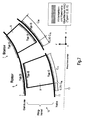
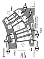
- the Fig.1 shows a schematic representation of the known from the prior art solutions. Shown are a schematic representation of a hub 11 and a housing 1, between which a fluid, as shown by the large arrow, flows from the left. Furthermore, a blade 2 is shown, which may be either a rotor 6 or stator 5 and whose visible area forms the suction side. As indicated by the arrows, there are designs for a local air supply at different locations of the fluid flow machine. For rotor and Statorbeschaufelschitch as well as flat Experimentalschaufelgitter it is known to inject between the leading edge and about 60% of the tread depth via slots 4 fluid on the blade suction side to affect the two-dimensional profile boundary layer. The necessary fluid enters from a hollow, pressurized interior of the blade 2 in the main flow path. In alternative solutions, the blade profile is split to allow for supply by direct passage of the fluid from the blade pressure side to the blade suction side.
- the present invention has for its object to provide a fluid flow machine of the type mentioned, which has a very effective boundary layer influencing by targeted fluid supply and high efficiency while avoiding the prior art.
- the turbomachine according to the invention may comprise one or more stages each having a rotor and a stator; in some cases, the stage is formed only by a rotor.
- the rotor consists of a number of blades, which are connected to the rotating shaft of the fluid flow machine and deliver energy to the working fluid.
- the rotor can be designed with or without shroud on the outer blade end.
- the stator according to the invention consists of a number of fixed blades, which can be designed on the hub side as the housing side with a fixed or free blade end.
- the rotor drum provided according to the invention and the blading are usually surrounded by a housing, in other cases, e.g. with propellers and propellers, no housing exists.
- the turbomachine may have a stator in front of the first rotor, a so-called leading wheel.
- at least one stator or Vorleitrad may be rotatably mounted deviating from the immovable fixation in order to change the angle of attack. An adjustment is made for example by a spindle accessible from outside the annular channel.
- the turbomachine may have at least one row of adjustable rotors.
- this has two counter-rotating waves at Mehrstufmaschine, so that the rotor blade rows change the direction of rotation from stage to stage. There are no stators between successive rotors.
- the fluid flow machine can alternatively also have a bypass configuration such that the single-flow annular channel divides behind a specific row of blades into two concentric annular channels, which in turn each comprise at least one further row of blades.
- a fluid flow machine which comprises means for supplying fluid to at least one blade of a blade row of the rotor and / or the stator at aerodynamically critical locations on trailing edge and edge surfaces (HRO).
- HRO trailing edge and edge surfaces
- the required openings on the wetted surfaces of the machine are arranged axially symmetrical, provided they are outside the boundaries of the bladed space given in the meridian view and are placed on protruding from the smooth annular channel wall in the main flow path.
- the required openings are arranged non-axisymmetrically, provided that they are outside the limits given in the meridian view lie bladed space and are provided flush with the smooth annular channel wall.
- the fluid flow machine on at least one blade of a rotor or stator series means for fluid supply, which are not selectively applied on the blade suction side in Meridianströmungsplatz, but over a defined area, and their Meridianerstreckung in meridianstromlinienorthogonaler direction at least one of the annular channel walls (hub or housing) decreases towards (suction side, intensity variable fluid supply SIFZ).
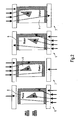
- the Fig. 2 shows a greatly simplified representation of the inventive solution to four differently configured rows of blades, each comprising a rotor 6 and a stator 7, which are provided with rotor blades 8 and stator blades 9.
- a housing or an outer shroud is reproduced in a greatly simplified representation.
- Reference numeral 11 denotes a rotor drum or an inner shroud.
- the selected view of the blade can represent both the suction side and the pressure side of the blade.
- a zone for suction-side intensity-variable fluid supply (SIFZ) is provided on rotors and stators.
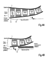
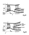
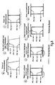
- the Fig. 4 shows four different configurations of the fluid flow machine according to the invention.
- the reference numeral 10 denotes a ring channel to be flowed through from left to right, with the reference numeral 13, the machine axis is shown, around which a rotor drum (hub) 11 rotates.
- a further rotor drum (hub) is provided in the embodiments shown in FIGS. 5B and 5D.
- the rotors, stators as well as the leader wheel are respectively in Fig. 5 labeled, it is shown in a schematic manner a blade.
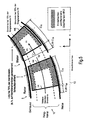
- Fig. 5 shows the definition of the trailing edge and near-edge surfaces (HRO) according to the invention. It is in turn simplified a rotor 6 and a stator 7 are shown, which are arranged in the annular channel 10 between a housing 1 and a hub (rotor drum) 11.
- HRO trailing edge and near-edge surfaces
- HRO, type B The surfaces are formed on the blade suction side, the blade pressure side, the leading edge or the trailing edge of a rotor or stator, at the hub between 0% and 25% of the local ring channel width W and on the housing between 75% and 100% the local ring channel width W.
- HRO, Type C The surfaces are formed on the hub or housing contour of the annular channel with a fixed connection to the blade, as in the case of platforms, shrouds, blisk and Blingkonfigurationen occur between the trailing edge plane HK and a plane that is 25% of the meridional blade chord length Cm is located in front of the leading edge VK.
- HRO, type D The surfaces on the hub and housing contours of the annular channel 10 are in the area of free blade ends (above Rotors without shroud or below stators without shroud) are formed between the trailing edge plane HK and a plane which is 35% of the meridional blade chord length Cm before the leading edge VK.
- HRO Type E: The surfaces are formed on blades at their free blade ends, which face the hub or the housing contour of the annular channel 10 (tip end surfaces of the blade).
- the Fig. 8b shows a variant with an assembly consisting of a rotor drum, a plurality of rotating with the drum rotor blades with free outer ends, as well as a surrounding the rotating parts and stationary housing.
- the Fig. 8c shows an assembly consisting of a stationary outer housing, a plurality of stator blades connected to the outer housing, as well as one of the stator blades on the inner circumference worn shroud and rotating within the stationary components rotor drum.
- the Fig. 8d shows an assembly consisting of a stationary outer housing, a plurality of stator blades connected to the outer housing with free inner ends and a rotating within the stationary components rotor drum.
- Fig. 8e For example, there is shown an assembly consisting of a stationary outer housing, a plurality of stator vanes connected to the outer housing with free inner ends, and an inner housing resting within the row of stator blades.
- the Fig. 8f shows an assembly consisting of a stationary inner housing, a plurality of stator blades connected to the inner housing with free outer ends, and an outer housing surrounding the Statorschaufelsch.
- the Fig. 8g illustrates an assembly, which consists of a stationary inner and outer housing, as well as several connected to the inner and outer housing stator blades.
- the guidance of the fluid to be supplied takes place via flow paths at the periphery of the annular channel 10 or within blades 8, 9 and their surrounding components.
- the fluid is supplied into the annular channel in the area of the relevant row of blades either with free flow or with the aid of at least one throttle element 12 located in the flow path, which can be adjustable or adjustable.
- the supply of the fluid either takes place from a foreign source or is returned from locations of the fluid flow machine or the overall plant enclosing the fluid flow machine.
- the necessary elements of the flow path can be designed as a simple cavity, as an annular space, as a pipeline, as a channel, as a nozzle or as a diffuser of any cross-sectional shape and are summarized below under the term "chamber".
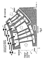
- Fig. 9 to 11 show different embodiments of the invention with configurations in which feed chambers (ZK), blade inner chambers (SK) and hub chambers (NK) are provided.
- each supply chamber ZK can communicate with and supply at least one blade inner chamber SK. If the blade has a fixed connection to the inner annular channel contour, then at least one chamber on or in the hub outside of the annular channel may exist as the last chamber member of the overall flow path designed for fluid supply (hub chamber NK) which communicates with at least one blade inner chamber SK and of this fluid receives.
- At least one supply chamber ZK can also exist on or in the hub outside the annular channel for supplying fluid to the hub.
- Feed chambers and hub chambers extend over all or part of the machine circumference.
- the feed chambers ZK serve to supply the fluid to the relevant row of blades, the blade inner chambers SK being hub chambers for providing access to the relevant trailing edge and peripheral surfaces (HRO) of the particular row of blades.
- each supply chamber ZK can communicate with and supply at least one blade inner chamber SK.
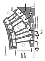
- At least one chamber on or in the housing may exist as the last chamber member of the overall flow path designed for fluid supply (housing chamber GK), which communicates with at least one blade inner chamber SK and receives fluid from there.
- At least one supply chamber can also be present on or in the housing outside the annular channel for supplying fluid to the housing.
- the feed chambers and housing chambers extend over all or only parts of the circumference of the fluid power machine.
- the feed chambers serve to supply the fluid to the relevant blade row.
- the bucket inner chambers and the housing chambers are tools to provide access to relevant trailing edge and near-edge surfaces (HRO) in the area of the particular blade row.
- At least one fluid supply device is arranged, which establishes a connection between the trailing edge and near-edge surfaces (HRO) and a supply chamber ZK, a blade inner chamber SK, a hub chamber NK or a housing chamber GK.
- the structural design of the fluid supply device takes place by means of mechanical, chemical or thermal material removal methods on the part forming the trailing edge and edge-near surface (HRO).
- the fluid supply device receives its limitations by combining at least two prepared individual components, which are joined together loosely or firmly.
- Fig. 15 and 16 Illustrate embodiments of the invention for the fluid supply device on trailing edge and near-surface surfaces (HRO) type B. Shown are configurations of slots or functionally similar replacement elements on the two near-edge portions of the blade surface, both valid for the suction side and the pressure side of the blade. Individual slots or replacement elements can be assigned to different blade inner chambers.
- HRO near-surface surfaces
- the ring channel heights HA and HE, as well as the hub distances hA and hE are measured in a direction perpendicular to the mean meridian endometrial line.
- each slot between the beginning and end point can be straight or curved.
- the slots have a constant or lengthwise variable width W, but always less than 5% of the meridional chord length Cm (W ⁇ 0.05 * Cm). They have square, chamfered or rounded surface edges. They have at the beginning and end of a square shape or a round (slot-like) degree.
- the slots lead vertically or obliquely at an angle of at least 5 ° to the blade surface through the wall material in the same blade inner chamber or different blade inner chambers.
- a particularly favorable influencing of the blade flow occurs when slots are arranged both on the blade suction side and on the blade pressure side.
- Fig. 16 shows this by way of example for a configuration of three slots in the hub and housing area.
- At least one slot continuous between points A and E will result in a series of multiple holes.
- it is particularly favorable if, in the case of the use of more than one row on the same blade side (pressure or suction side), holes and interstices occur alternately when viewed along a meridional flow line.
- At least one fluid supply device is formed as a flat nozzle, characterized in that fluid is at most 30 ° to the blade surface is supplied and the blade surface has a corresponding paragraph.
- turbomachine In the case of the turbomachine according to the invention, an unprecedented degree of boundary layer influencing is thus achieved. This is possible with different types of turbomachines such as fans, compressors, pumps and fans or even with propellers and propellers. Depending on the design variant, an aerodynamic load and a flow deflection are possible, which are up to 50% above the values achieved according to the current state of the art. For fixed power values of a fluid flow machine can be while maintaining or improving the efficiency of up to 1% reduce the number of installed parts by about 30% compared to a conventional construction. The costs decrease by 10% to 15%. Using the new bucket concept in the compressor of an aircraft engine with approximately 25,000 pounds of thrust results in a reduction in specific fuel consumption of up to 0.5% and a weight saving of around 5%.
Landscapes
- Engineering & Computer Science (AREA)
- Mechanical Engineering (AREA)
- General Engineering & Computer Science (AREA)
- Physics & Mathematics (AREA)
- Fluid Mechanics (AREA)
- Structures Of Non-Positive Displacement Pumps (AREA)
Abstract
Description
Die vorliegende Erfindung bezieht sich auf Strömungsarbeitsmaschinen wie etwa Bläser, Verdichter, Pumpen und Ventilatoren, sowohl in axialer, halbaxialer als auch in radialer Bauart. Das Arbeitsmedium oder Fluid kann gasförmig oder flüssig sein.The present invention relates to fluid flow machines such as fans, compressors, pumps and fans, in both axial, semi-axial and radial designs. The working medium or fluid may be gaseous or liquid.
Im Einzelnen betrifft die Erfindung eine Strömungsarbeitsmaschine mit zumindest einem Rotor, wobei der Rotor mehrere an einer rotierenden Welle befestigte Rotorschaufeln umfasst. Es kann mindestens ein Stator existieren, wobei der Stator mit feststehenden Statorschaufeln versehen ist. Es kann ein Gehäuse existieren, welches die Durchströmung des Rotors und des Stators mit einem Fluid nach außen begrenzt.More particularly, the invention relates to a fluid power machine having at least one rotor, the rotor comprising a plurality of rotor blades secured to a rotating shaft. At least one stator may exist, the stator being provided with stationary stator blades. There may be a housing which limits the flow of the rotor and the stator with a fluid to the outside.
Die aerodynamische Belastbarkeit und die Effizienz von Strömungsarbeitsmaschinen, beispielsweise Bläsern, Verdichtern, Pumpen und Ventilatoren, wird durch das Wachstum und die Ablösung von Grenzschichten auf den Schaufeln sowie auf den Naben-und Gehäusewänden begrenzt. Der Stand der Technik hält für dieses fundamentale Problem nur bedingt Lösungen bereit. Es existieren zahlreiche Konzepte zur Fluidzufuhr an Turbinenschaufeln, doch sind diese nicht auf Strömungsarbeitsmaschinen übertragbar, da sie im wesentlichen der Oberflächenkühlung und nicht der Grenzschichtenergetisierung dienen. Aus Verdichtergitterexperimenten sind Konzepte bekannt, bei denen aus einer druckbeaufschlagten Kammer im Schaufelinnern Luft auf die Schaufelsaugseite ausgeblasen wird, um die zweidimensional beschaffene Profilgrenzschicht zu energetisieren. Verwandte Alternativlösungen sehen ein direktes Durchtreten des Fluides von der Schaufeldruckseite zur Schaufelsaugseite vor. Daneben existiert für Rotoren ein Konzept zur Luftzufuhr an Nabe und Gehäuse durch achsensymmetrisch angeordnete Schlitze, um die dortigen Wandgrenzschichten zu beeinflussen. Schließlich gibt es Veröffentlichungen von Forschungsinstitutionen, die Konzepte aufzeigen, bei denen Rotoren in Gehäusenähe aus einzelnen Düsen angeblasen werden, um die dortige Radialspaltströmung günstig zu beeinflussen. Der allgemeine Gedanke der Grenzschichtbeeinflussung durch Einblasung bzw. Fluidzufuhr ist somit im Stand der Technik enthalten, doch sind die bekannten Lösungen trivial und nur bedingt effektiv.The aerodynamic load capacity and efficiency of fluid flow machines, such as fans, compressors, pumps and fans, is limited by the growth and separation of boundary layers on the blades and on the hub and casing walls. The state of the art provides only limited solutions to this fundamental problem. There are numerous concepts for fluid delivery to turbine blades, but these are not transferable to fluid flow machines as they essentially serve for surface cooling rather than boundary layer energization. Condensing grating experiments have disclosed concepts in which air is blown out of a pressurized chamber in the interior of the blade onto the blade suction side in order to energize the two-dimensional profile boundary layer. Related alternative solutions provide for direct passage of the fluid from the blade pressure side to the blade suction side. In addition, there is a concept for rotors for supplying air to the hub and housing by axially symmetrically arranged slots in order to influence the wall boundary layers there. Finally, there are publications of research institutions, the concepts show, in which rotors are blown close to the housing from individual nozzles in order to influence the local radial gap flow low. The general idea of the boundary layer influencing by injection or fluid supply is thus included in the prior art, but the known solutions are trivial and only partially effective.
Die
Für den Fall eines Rotors ist es bekannt, vor oder innerhalb des Bereichs der vorderen 50% der Profiltiefe durch einen achsensymmetrisch angeordneten Schlitz 3 Fluid an der Nabe 11 und/oder am Gehäuse 1 zuzuführen, um eine Beeinflussung der Wandgrenzschichten zu erreichen. Für Rotoren mit Gehäuseradialspalt existieren zudem Konzepte, die vorsehen, durch eine Anzahl von in den Strömungspfad vorstehenden Düsen 3 am Gehäuse Fluid punktuell einzublasen, um an diskreten Orten des Umfangs auf die Spaltströmung des Rotors Einfluss zu nehmen.In the case of a rotor, it is known to supply fluid to the
Lediglich eine hier nicht dargestellte Lösung sieht eine Entnahme auf der Schaufelsaugseite und ein Wiedereinströmen an anderer Stelle derselben Schaufel, nämlich der Schaufelspitze vor.Only one solution, not shown here, provides for removal on the blade suction side and reentry elsewhere in the same blade, namely the blade tip.
Der Stand der Technik beschreibt somit die folgenden Methoden einer Zufuhr von Fluid:
- 1.) durch gerade Schlitze im vorderen oder mittleren Bereich der Schaufelsaugseite an Rotoren und Statoren
- 2.) durch achsensymmetrische, flächenbündige Schlitze in Nabe und/oder Gehäuse weit vor der Schaufelhinterkante an Rotoren mit Gehäuseradialspalt
- 3.) durch eine Anzahl am Umfang verteilter, vorstehender Einzeldüsen am Gehäuse vor Rotoren mit Gehäuseradialspalt.
- 1.) through straight slots in the front or middle area of the Schaufelsaugseite to rotors and stators
- 2.) by axially symmetric, flush-fitting slots in the hub and / or housing far ahead of the blade trailing edge on rotors with Gehäuseradialspalt
- 3.) by a number distributed on the circumference, projecting individual nozzles on the housing before rotors with Gehäuseradialspalt.
Die meisten dieser Konzepte sind nur bedingt auf strömungstechnisch besonders problematische Zonen innerhalb der Schaufelpassage ausgerichtet oder orientieren sich an der einfachen Vorstellung einer zweidimensionalen Profilumströmung ohne die Berücksichtigung der komplizierten dreidimensionalen Strömungsvorgänge im Seitenwandbereich (nahe an Nabe und Gehäuse). Andere sind trotz ihrer Ausrichtung auf lokal kritische Strömungszonen von begrenzter Wirksamkeit.Most of these concepts are limited in terms of fluidically particularly problematic zones within the blade passage or are based on the simple idea of a two-dimensional profile flow without taking into account the complicated three-dimensional flow processes in the sidewall area (close to the hub and housing). Others are of limited effectiveness despite their orientation to locally critical flow zones.
Üblicherweise wird beim Stand der Technik Hilfsluft höheren Druckes von extern zugeführt. Lediglich ein Patent sieht eine Luftversorgung von Schlitzen einer weiter stromab gelegenen Stelle der Strömungsarbeitsmaschine vor.Usually, in the prior art, auxiliary air of higher pressure is externally supplied. Only one patent provides for air supply to slots of a downstream location of the fluid power machine.
Der oben beschriebene Stand der Technik ist schriftlich in nachfolgenden Veröffentlichungen dokumentiert:
-
US 5,690,473 -
US 6,334,753 -
US 2,870,957 -
US 2,933,238 -
US 5,480,284
-
US 5,690,473 -
US 6,334,753 -
US 2,870,957 -
US 2,933,238 -
US 5,480,284
Als nachteilig erweist sich beim Stand der Technik, dass die existierenden Lösungen keine hochwirksamen und insbesondere hinsichtlich des Wirkungsgrades der Strömungsarbeitsmaschine günstigen Lösungen bilden. Vielmehr sind die existierenden Einblasekonzepte vergleichsweise primitiv und sehen entweder die alleinige Einblasung auf der Schaufelsaugseite vor oder kombinieren dies mit einer Einblasung vor oder in der Schaufelreihe durch achsensymmetrische Ringschlitze an Nabe und/oder Gehäuse. Offensichtlich fehlen Konzepte zur gezielten Strömungsbeeinflussung im randnahen Bereich und zur radial (in Schaufelhöhenrichtung) variablen Beeinflussung der Profilgrenzschichten. Eine nicht achsensymmetrische Fluidzufuhr an den Seitenwänden vor oder innerhalb des beschaufelten Region oder auch an Schaufelspitzen im Laufspalt wird nicht in Betracht gezogen, obwohl die Beeinflussung der Seitenwandgrenzschichten am Ort der Problementstehung besonders ratsam ist. Diese gezielte Beeinflussung der dreidimensionalen Strömungsvorgänge im Bereich der Schaufelenden (und des damit verbundenen Strömungsaustausches in Schaufelhöhenrichtung) wird durch existierende Konzepte nicht berücksichtigt.A disadvantage proves in the prior art that the existing solutions do not form highly effective and in particular with regard to the efficiency of the fluid flow machine solutions. Rather, the existing Einblasekonzepte are relatively primitive and either provide the sole injection on the blade suction side or combine this with an injection before or in the blade row by axisymmetric annular slots on the hub and / or housing. Obviously, concepts for targeted flow control in the near-edge region and for the radial (in blade height direction) variable influencing of the profile boundary layers are missing. Non-axisymmetric fluid delivery to the sidewalls before or within the bladed region, or even blade tips in the nip, is not contemplated, although interfacing with sidewall interfaces at the site of the problem is particularly desirable. This targeted influencing of the three-dimensional flow processes in the area of the blade ends (and the associated flow exchange in the blade height direction) is not taken into account by existing concepts.
Der vorliegenden Erfindung liegt die Aufgabe zugrunde, eine Strömungsarbeitsmaschine der eingangs genannten Art zu schaffen, welche unter Vermeidung des Standes der Technik eine sehr wirkungsvolle Grenzschichtbeeinflussung durch gezielte Fluidzufuhr sowie einen hohen Wirkungsgrad aufweist.The present invention has for its object to provide a fluid flow machine of the type mentioned, which has a very effective boundary layer influencing by targeted fluid supply and high efficiency while avoiding the prior art.
Erfindungsgemäß wird die Aufgabe durch die Merkmalskombination des Hauptanspruchs gelöst, die Unteransprüche zeigen weitere vorteilhafte Ausgestaltungen der Erfindung.According to the invention the object is achieved by the feature combination of the main claim, the subclaims show further advantageous embodiments of the invention.
Die erfindungsgemäße Strömungsarbeitsmaschine kann eine oder mehrere Stufen mit jeweils einem Rotor und einem Stator umfassen; in Einzelfällen wird die Stufe lediglich durch einen Rotor gebildet.The turbomachine according to the invention may comprise one or more stages each having a rotor and a stator; in some cases, the stage is formed only by a rotor.
Erfindungsgemäß besteht der Rotor aus einer Anzahl von Schaufeln, die mit der rotierenden Welle der Strömungsarbeitsmaschine verbunden sind und Energie an das Arbeitsmedium abgeben. Der Rotor kann mit oder ohne Deckband am äußeren Schaufelende ausgeführt sein. Der erfindungsgemäße Stator besteht aus einer Anzahl feststehender Schaufeln, die nabenseitig wie gehäuseseitig mit festem oder freiem Schaufelende ausgeführt sein können.According to the invention, the rotor consists of a number of blades, which are connected to the rotating shaft of the fluid flow machine and deliver energy to the working fluid. The rotor can be designed with or without shroud on the outer blade end. The stator according to the invention consists of a number of fixed blades, which can be designed on the hub side as the housing side with a fixed or free blade end.
Die erfindungsgemäß vorgesehene Rotortrommel und die Beschaufelung sind üblicherweise von einem Gehäuse umgeben, in anderen Fällen, z.B. bei Propellern und Schiffsschrauben, existiert kein Gehäuse.The rotor drum provided according to the invention and the blading are usually surrounded by a housing, in other cases, e.g. with propellers and propellers, no housing exists.
Erfindungsgemäß kann die Strömungsarbeitsmaschine einen Stator vor dem ersten Rotor aufweisen, ein sogenanntes Vorleitrad. Erfindungsgemäß kann mindestens ein Stator oder Vorleitrad abweichend von der unbeweglichen Fixierung auch drehbar gelagert sein, um den Anströmwinkel zu verändern. Eine Verstellung erfolgt beispielsweise durch eine von außerhalb des Ringkanals zugängliche Spindel.According to the invention, the turbomachine may have a stator in front of the first rotor, a so-called leading wheel. According to the invention, at least one stator or Vorleitrad may be rotatably mounted deviating from the immovable fixation in order to change the angle of attack. An adjustment is made for example by a spindle accessible from outside the annular channel.
In besonderer Ausgestaltung kann die Strömungsarbeitsmaschine mindestens eine Reihe verstellbarer Rotoren aufweisen.In a particular embodiment, the turbomachine may have at least one row of adjustable rotors.
In einer alternativen Ausgestaltung der erfindungsgemäßen Strömungsarbeitsmaschine kann auch vorgesehen sein, dass diese bei Mehrstufigkeit zwei gegenläufige Wellen besitzt, so dass die Rotorschaufelreihen von Stufe zu Stufe die Drehrichtung wechseln. Hierbei existieren keine Statoren zwischen aufeinander folgenden Rotoren.In an alternative embodiment of the fluid flow machine according to the invention can also be provided that this has two counter-rotating waves at Mehrstufigkeit, so that the rotor blade rows change the direction of rotation from stage to stage. There are no stators between successive rotors.
Erfindungsgemäß kann die Strömungsarbeitsmaschine alternativ auch eine Nebenstromkonfiguration derart aufweisen, dass sich der einstromige Ringkanal hinter einer bestimmten Schaufelreihe in zwei konzentrische Ringkanäle aufteilt, die ihrerseits mindestens jeweils eine weitere Schaufelreihe umfassen.According to the invention, the fluid flow machine can alternatively also have a bypass configuration such that the single-flow annular channel divides behind a specific row of blades into two concentric annular channels, which in turn each comprise at least one further row of blades.
Erfindungsgemäß ist somit im Einzelnen eine Strömungsarbeitsmaschine geschaffen worden, die Mittel zur Zufuhr von Fluid an mindestens einer Schaufel einer Schaufelreihe des Rotors und/oder des Stators an aerodynamisch kritischen Orten auf hinterkanten- und randnahen Oberflächen (HRO) umfasst. Dabei sind die erforderlichen Öffnungen an den benetzten Oberflächen der Maschine achsensymmetrisch angeordnet, sofern sie außerhalb der in der Meridianansicht gegebenen Grenzen des beschaufelten Raumes liegen und an von der glatten Ringkanalwand in den Hauptströmungspfad vorstehenden Orten plaziert sind. Die erforderlichen Öffnungen sind nicht-achsensymmetrisch angeordnet, sofern sie außerhalb der in der Meridianansicht gegebenen Grenzen des beschaufelten Raumes liegen und bündig mit der glatten Ringkanalwand vorgesehen sind.Thus, according to the invention, a fluid flow machine has been provided which comprises means for supplying fluid to at least one blade of a blade row of the rotor and / or the stator at aerodynamically critical locations on trailing edge and edge surfaces (HRO). In this case, the required openings on the wetted surfaces of the machine are arranged axially symmetrical, provided they are outside the boundaries of the bladed space given in the meridian view and are placed on protruding from the smooth annular channel wall in the main flow path. The required openings are arranged non-axisymmetrically, provided that they are outside the limits given in the meridian view lie bladed space and are provided flush with the smooth annular channel wall.
Alternativ oder zusätzlich zu Fluidzufuhrvorrichtungen an HRO weist die Strömungsarbeitsmaschine erfindungsgemäß an mindestens einer Schaufel einer Rotor- oder Statorreihe Mittel zur Fluidzufuhr auf, die auf der Schaufelsaugseite in Meridianströmungsrichtung nicht punktuell, sondern über einen definierten Bereich verteilt angelegt sind, und deren Meridianerstreckung in meridianstromlinienorthogonaler Richtung zu wenigstens einer der Ringkanalwände (Nabe oder Gehäuse) hin abnimmt (saugseitige, intensitätsvariable Fluidzufuhr SIFZ).Alternatively or in addition to fluid supply devices to HRO, the fluid flow machine according to the invention on at least one blade of a rotor or stator series means for fluid supply, which are not selectively applied on the blade suction side in Meridianströmungsrichtung, but over a defined area, and their Meridianerstreckung in meridianstromlinienorthogonaler direction at least one of the annular channel walls (hub or housing) decreases towards (suction side, intensity variable fluid supply SIFZ).
Im Folgenden wird die Erfindung anhand von Ausführungsbeispielen in Verbindung mit den Figuren beschrieben. Dabei zeigt:
- Fig.1:
- eine schematische Darstellung des Standes der Technik
- Fig.2:
- eine schematische Darstellung von Varianten des erfindungsgemäßen Grundkonzeptes
- Fig.3:
- eine weitere schematische Darstellung von Vari- anten des erfindungsgemäßen Grundkonzeptes
- Fig.4:
- verschiedene Varianten und Konfigurationen der erfindungsgemäßen Strömungsarbeitsmaschine
- Fig.5:
- eine Darstellung zur erfindungsgemäßen Definiti- on des Begriffs HRO
- Fig.6:
- eine Darstellung zur erfindungsgemäßen Definiti- on von HRO, Typen A und B
- Fig.7:
- eine Darstellung zur erfindungsgemäßen Definiti- on von HRO, Typen C, D und E
- Fig.8:
- eine weitere Darstellung zur erfindungsgemäßen Definition von HRO, Typen C, D und E
- Fig.9 bis 11:
- unterschiedliche Ausgestaltungsformen von Kam- mern zur Zuführung des Fluids, vornehmlich vom Gehäuse aus
- Fig.12 bis 14:
- Ausgestaltungsvarianten analog
Fig.9 mit Kammern zur Zuführung des Fluids, vornehmlich von der Nabe ausbis 11 - Fig.15 und 16:
- erfindungsgemäße Ausführungsvarianten einer Flu- idzufuhrvorrichtung an Hinterkanten- und Randna- hen Oberflächen (HRO) des Typs B
- Fig.1:
- a schematic representation of the prior art
- Figure 2:
- a schematic representation of variants of the basic concept of the invention
- Figure 3:
- a further schematic representation of variants of the basic concept according to the invention
- Figure 4:
- Various variants and configurations of the flow machine according to the invention
- Figure 5:
- a representation of the definition according to the invention of the term HRO
- Figure 6:
- a representation of the inventive definition of HRO, types A and B.
- Figure 7:
- a representation of the inventive definition of HRO, types C, D and E.
- Figure 8:
- a further illustration of the inventive definition of HRO, types C, D and E.
- Fig.9 to 11:
- different embodiments of chambers for supplying the fluid, mainly from the housing
- FIGS. 12 to 14:
-
Design variants analog 9 to 11 with chambers for supplying the fluid, primarily from the hub - FIGS. 15 and 16:
- Inventive variants of a fluid supply device on trailing edge and peripheral surfaces (HRO) of type B
Die
In analoger Weise zeigt
Die
Die
Wie die Darstellungen in
- HRO, Typ A: Die Oberflächen sind an der Schaufelsaug- oder Druckseite eines Rotors oder Stators ausgebildet, und zwar zwischen 70% und 100% der meridionalen Schaufelsehnenlänge Cm. O-berflächenabschnitte im zentralen Bereich der Hinterkante, deren Oberflächennormale einen Winkel von weniger als 60 Grad mit der mittleren Abströmrichtung bildet, sind dabei ausgeschlossen.
- HRO Type A: The surfaces are formed on the blade suction or pressure side of a rotor or stator, between 70% and 100% of the meridional blade chord length Cm. O-berflächenabschnitte in the central region of the trailing edge, the surface normal forms an angle of less than 60 degrees with the central outflow, are excluded.
HRO, Typ B: Die Oberflächen sind an der Schaufelsaugseite, der Schaufeldruckseite, der Vorderkante oder der Hinterkante eines Rotors oder Stators ausgebildet, und zwar an der Nabe zwischen 0% und 25% der lokalen Ringkanalweite W und am Gehäuse zwischen 75% und 100% der lokalen Ringkanalweite W.HRO, type B: The surfaces are formed on the blade suction side, the blade pressure side, the leading edge or the trailing edge of a rotor or stator, at the hub between 0% and 25% of the local ring channel width W and on the housing between 75% and 100% the local ring channel width W.
HRO, Typ C: Die Oberflächen sind an der Naben- oder Gehäusekontur des Ringkanals mit fester Verbindung zur Schaufel ausgebildet, wie sie im Fall von Plattformen, Deckbändern, Blisk- und Blingkonfigurationen auftreten, und zwar zwischen der Hinterkantenebene HK und einer Ebene, die sich 25% der meridionalen Schaufelsehnenlänge Cm vor der Vorderkante VK befindet.HRO, Type C: The surfaces are formed on the hub or housing contour of the annular channel with a fixed connection to the blade, as in the case of platforms, shrouds, blisk and Blingkonfigurationen occur between the trailing edge plane HK and a plane that is 25% of the meridional blade chord length Cm is located in front of the leading edge VK.
HRO, Typ D: Die Oberflächen sind an Naben- und Gehäusekontur des Ringkanals 10 im Bereich freier Schaufelenden (oberhalb von Rotoren ohne Deckband oder unterhalb von Statoren ohne Deckband) zwischen der Hinterkantenebene HK und einer Ebene, die sich 35% der meridionalen Schaufelsehnenlänge Cm vor der Vorderkante VK befindet, ausgebildet.HRO, type D: The surfaces on the hub and housing contours of the
HRO, Typ E: Die Oberflächen sind an Schaufeln an deren freien Schaufelenden ausgebildet, die der Naben- oder der Gehäusekontur des Ringkanals 10 zugewandt sind (Spitzenstirnflächen der Schaufel).HRO, Type E: The surfaces are formed on blades at their free blade ends, which face the hub or the housing contour of the annular channel 10 (tip end surfaces of the blade).
Die
- Die
Fig. 8a zeigt eine Baugruppe, bestehend aus einer Rotortrommel, mit mehreren mit der Trommel rotierenden Rotorschaufeln, einem die Rotorschaufeln am äußeren Umfang umgebenden und mitrotierenden Deckband sowie einem die rotierenden Teile umgebenden und ruhenden Gehäuse.
- The
Fig. 8a shows an assembly consisting of a rotor drum, with a plurality of rotor blades rotating with the drum, a surrounding the rotor blades on the outer circumference and co-rotating shroud and surrounding the rotating parts and stationary housing.
Die
Die
Die
Aus
Die
Die
Erfindungsgemäß erfolgt die Führung des zuzuführenden Fluids über Strömungswege an der Peripherie des Ringkanals 10 oder innerhalb von Schaufeln 8, 9 und ihrer umgebenden Bauteile. Erfindungsgemäß wird das Fluid dabei entweder bei freier Strömung oder aber mit Hilfe mindestens eines im Strömungsweg befindlichen Drosselorgans 12, das unverstellbar oder auch regelbar sein kann, in den Ringkanal im Bereich der betreffenen Schaufelreihe zugeführt. Die Zuführung des Fluids erfolgt entweder von einer Fremdquelle aus oder wird von Orten der Strömungsarbeitsmaschine oder der die Strömungsarbeitsmaschine einschließenden Gesamtanlage zurückgeführt.According to the invention, the guidance of the fluid to be supplied takes place via flow paths at the periphery of the
Die notwendigen Elemente des Strömungsweges können erfindungsgemäß als einfacher Hohlraum, als Ringraum, als Rohrleitung, als Kanal, als Düse oder als Diffusor beliebiger Querschnittsform ausgestaltet sein und werden erfindungsgemäß im Folgenden unter dem Begriff "Kammer" zusammengefasst.According to the invention, the necessary elements of the flow path can be designed as a simple cavity, as an annular space, as a pipeline, as a channel, as a nozzle or as a diffuser of any cross-sectional shape and are summarized below under the term "chamber".
Die
Im Einzelnen zeigen die
Besitzt die Schaufel ein freies Ende mit Radialspalt an der Nabe, oder weist die Schaufel keine über die gesamte Schaufelhöhe reichende Schaufelinnenkammer auf, kann zur Fluidzufuhr an der Nabe ebenfalls mindestens eine Zufuhrkammer ZK an oder in der Nabe außerhalb des Ringkanals existieren.If the blade has a free end with a radial gap at the hub, or if the blade does not have a blade inner chamber extending over the entire blade height, at least one supply chamber ZK can also exist on or in the hub outside the annular channel for supplying fluid to the hub.
Zufuhrkammern und Nabenkammern erstrecken sich über die Gesamtheit oder Teile des Maschinenumfangs. Die Zufuhrkammern ZK dienen der Zuleitung des Fluids zur betreffenden Schaufelreihe, wobei die Schaufelinnenkammern SK Nabenkammern Hilfsmittel sind, um den Zugang zu den relevanten Hinterkanten- und Randnahen Oberflächen (HRO) der betreffenden Schaufelreihe herzustellen.Feed chambers and hub chambers extend over all or part of the machine circumference. The feed chambers ZK serve to supply the fluid to the relevant row of blades, the blade inner chambers SK being hub chambers for providing access to the relevant trailing edge and peripheral surfaces (HRO) of the particular row of blades.
Während in den
Besitzt die Schaufel ein freies Ende mit Radialspalt am Gehäuse oder weist die Schaufel keine über die gesamte Schaufelhöhe reichende Schaufelinnenkammer auf, kann zur Fluidzufuhr am Gehäuse ebenfalls mindestens eine Zufuhrkammer am oder im Gehäuse außerhalb des Ringkanals existieren.If the blade has a free end with a radial gap on the housing or if the blade does not have a blade inner chamber extending over the entire blade height, at least one supply chamber can also be present on or in the housing outside the annular channel for supplying fluid to the housing.
Die Zufuhrkammern und Gehäusekammern erstrecken sich über die Gesamtheit oder nur Teile des Umfangs der Strömungsarbeitsmaschine. Die Zufuhrkammern dienen der Zuleitung des Fluids zu der betreffenden Schaufelreihe. Die Schaufelinnenkammern und die Gehäusekammern sind Hilfsmittel, um den Zugang zu relevanten Hinterkanten- und Randnahen Oberflächen (HRO) im Bereich der betreffenden Schaufelreihe herzustellen.The feed chambers and housing chambers extend over all or only parts of the circumference of the fluid power machine. The feed chambers serve to supply the fluid to the relevant blade row. The bucket inner chambers and the housing chambers are tools to provide access to relevant trailing edge and near-edge surfaces (HRO) in the area of the particular blade row.
Erfindungsgemäß ist vorgesehen, dass bei einer Schaufelreihe der im Zusammenhang mit den
In einer alternativen Ausgestaltung der Erfindung erhält die Fluidzufuhrvorrichtung ihre Begrenzungen durch Kombination mindestens zweier vorbereiteter Einzelbauteile, die lose oder fest zusammengefügt werden.In an alternative embodiment of the invention, the fluid supply device receives its limitations by combining at least two prepared individual components, which are joined together loosely or firmly.
Die
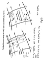
Betrachtet man die Schaufeloberfläche in dem aus Axialrichtung und Radialrichtung gebildeten Koordinatensystem (x, r), siehe Fig. 20, so ergibt sich durch eine äquidistante Teilung der auf der mittleren Meridianstromlinie basierten Othogonalen eine Schar von Meridianstromlinien. Die Meridianstromlinien auf den zwei Ringkanalhöhen h/H=0,25 und h/H=0,75 begrenzen die für HRO, Typ B vorgesehenen, eng entlang der Ringkanalwände verlaufenden Oberflächenzonen. Für die Fluidzufuhrvorrichtung sind Zonen zwischen der Nabe und der Grenzmeridianstromlinie bei h/H=0,25 beziehungsweise zwischen der Grenzmeridianstromlinie bei h/H=0,75 und dem Gehäuse vorgesehen. Jeder Schlitz der Fluidzufuhrvorrichtung verläuft zwischen einem Anfangspunkt A und einem Endpunkt E. Die Lage der Punkte A und E ist in meridionaler Richtung durch die Vorder- und Hinterkante der Schaufel eingeschränkt. Innerhalb dieser besonders relevanten, engen, randnahen Bereiche befindet sich eine Konfiguration aus einem oder auch mehreren Schlitzen, die orthogonal zur Meridianrichtung unterschiedliche Erstreckung besitzen dürfen. Dies ist in
- in Nabennähe durch 0 < hA < 0,25*HA und 0 < hE < 0,25*HE und/oder
- in
Gehäusenähe durch 0,75*HA < hA <HA und 0,75*HE < hE < HE.
- near the hub by 0 <hA <0.25 * HA and 0 <hE <0.25 * HE and / or
- near the housing 0.75 * HA <hA <HA and 0.75 * HE <hE <HE.
Die Ringkanalhöhen HA und HE, und ebenso die Nabenabstände hA und hE werden in einer Richtung senkrecht zur mittleren Meridianstomlinie gemessen.The ring channel heights HA and HE, as well as the hub distances hA and hE are measured in a direction perpendicular to the mean meridian endometrial line.
Der Verlauf eines jeden Schlitzes zwischen Anfangs- und Endpunkt kann gerade oder auch gekrümmt beschaffen sein. Die Schlitze besitzen eine konstante oder eine in ihrer Längsrichtung veränderliche Weite W, die aber stets kleiner als 5% der meridionalen Sehnenlänge Cm bleibt (W < 0,05*Cm). Sie weisen eckige, angefaste oder gerundete Oberflächenkanten auf. Sie besitzen an Anfangs- und Endpunkt eine eckige Form oder einen runden (langlochähnlichen) Abschluss. Die Schlitze führen senkrecht oder schräg unter einem Winkel von mindestens 5° zur Schaufeloberfläche durch das Wandmaterial in dieselbe Schaufelinnenkammer oder auch unterschiedliche Schaufelinnenkammern.The course of each slot between the beginning and end point can be straight or curved. The slots have a constant or lengthwise variable width W, but always less than 5% of the meridional chord length Cm (W <0.05 * Cm). They have square, chamfered or rounded surface edges. They have at the beginning and end of a square shape or a round (slot-like) degree. The slots lead vertically or obliquely at an angle of at least 5 ° to the blade surface through the wall material in the same blade inner chamber or different blade inner chambers.
Erfindungsgemäß ergibt sich eine strömungstechnisch besonders günstige Lösung, wenn Schlitze auf der Schaufelsaugseite innerhalb eines engen, wie folgt begrenzten Abschnittes angeordnet werden: ![]()

und dabei die Verbindungslinie zwischen Anfangspunkt A und Endpunkt E eines jeden Schlitzes mit der Meridianströmungsrichtung einen Winkel von 80° bis 110° einschließt (80 <= alpha <= 110).According to the invention results in a fluidically particularly favorable solution when slots on the Schaufelsaugseite within a narrow, as follows limited section are arranged: ![]()
and the connecting line between the starting point A and the end point E of each slot having the meridional flow direction encloses an angle of 80 ° to 110 ° (80 <= α <= 110).
Erfindungsgemäß ist es ebenso besonders günstig, Schlitze auf der Schaufeldruckseite innerhalb eines engen, wie folgt begrenzten Korridors anzuordnen: ![]()
![]()
und dabei die Verbindungslinie zwischen Anfangspunkt A und Endpunkt E eines jeden Schlitzes mit der Meridianströmungsrichtung einen Winkel von 80° bis 110° einschließt (80 <= alpha <= 110).In accordance with the invention, it is also particularly advantageous to arrange slots on the blade pressure side within a narrow corridor defined as follows: ![]()
![]()
and the connecting line between the starting point A and the end point E of each slot having the meridional flow direction encloses an angle of 80 ° to 110 ° (80 <= α <= 110).
Erfindungsgemäß ergibt sich schließlich eine besonders günstige Beeinflussung der Schaufelumströmung, wenn Schlitze sowohl auf der Schaufelsaugseite als auch auf der Schaufeldruckseite angeordnet werden.
In einer abgewandelten Form tritt -bei gleichen Regeln hinsichtlich der Positionierung und des Verlaufes an der Schaufeloberfläche sowie der Beschaffenheit der Oberflächenkanten und Orientierung in der Schaufel- an die Stelle mindestens eines zwischen den Punkten A und E durchgängigen Schlitzes eine Reihe aus mehreren kurzen Schlitzen mit dazwischen befindlichen Lücken beziehungsweise Stegen. Dabei ist es insbesondere günstig, wenn im Falle der Verwendung von mehr als einer Reihe auf derselben Schaufelseite (Druck- oder Saugseite) Kurzschlitze und Stege bei Betrachtung entlang einer Meridianstromlinie abwechselnd auftreten.In a modified form, with the same rules as to the positioning and progression of the blade surface and the nature of the surface edges and orientation in the blade, there will be a series of multiple short slots in between at least one slot passing between points A and E located gaps or webs. It is particularly favorable, if, in the case of using more than one row on the same blade side (pressure or suction side), short slits and lands occur alternately when viewed along a meridional flow line.
In einer anderen abgewandelten Form tritt -bei gleichen Regeln hinsichtlich der Positionierung und des Verlaufes an der Schaufeloberfläche sowie der Beschaffenheit der Oberflächenkanten und Orientierung in der Schaufel- an die Stelle mindestens eines zwischen den Punkten A und E durchgängigen Schlitzes eine Reihe aus mehreren Löchern. Dabei ist es insbesondere günstig, wenn im Falle der Verwendung von mehr als einer Reihe auf derselben Schaufelseite (Druck- oder Saugseite) Löcher und Lochzwischenräume bei Betrachtung entlang einer Meridianstromlinie abwechselnd auftreten.In another modified form, with the same rules as to the positioning and progression of the blade surface and the nature of the surface edges and orientation in the blade, at least one slot continuous between points A and E will result in a series of multiple holes. In this case, it is particularly favorable if, in the case of the use of more than one row on the same blade side (pressure or suction side), holes and interstices occur alternately when viewed along a meridional flow line.
In einer anderen abgewandelten Form wird -bei gleichen Regeln hinsichtlich der Positionierung und des Verlaufes an der Schaufeloberfläche sowie der Beschaffenheit der Oberflächenkanten - mindestens eine Fluidzufuhrvorrichtung (Schlitz, Kurzschlitzreihe oder Lochreihe) als Flachdüse ausgeformt, dadurch gekennzeichnet, dass Fluid unter höchstens 30° zur Schaufeloberfläche zugeführt wird und die Schaufeloberfläche einen entsprechenden Absatz aufweist.In another modified form, with the same rules regarding the positioning and the progression on the blade surface and the nature of the surface edges, at least one fluid supply device (slot, short slot row or row of holes) is formed as a flat nozzle, characterized in that fluid is at most 30 ° to the blade surface is supplied and the blade surface has a corresponding paragraph.
Eine besonders günstige Ausgestaltung gemäß der vorliegenden Erfindung ist durch das gemeinsame Auftreten der folgenden Ausgestaltungsmerkmale gegeben:
- 1.) eine Flachdüse zur Fluidzufuhr an einer Stelle der Schaufeldruckseite zwischen 85% der Profilsehnenlänge C und der Hinterkante, d.h. 0,85 < (x+y)/C < 1.
- 2.) die Portionen x und y der Sehnenlänge stehen in einem Verhältnis von mindestens x/y = 1,5.
- 3.) die über die Strecke x erreichte Richtungswinkeländerung der Tangente an die Druckseitenoberfäche ist kleiner als die über die Strecke y erreichte Richtungswinkeländerung der Tangente an die Druckseitenoberfäche.
- 1.) a flat nozzle for fluid supply at a position of the blade pressure side between 85% of the chord C and the trailing edge, ie 0.85 <(x + y) / C <1.
- 2.) The portions x and y of the chord length are in a ratio of at least x / y = 1.5.
- 3.) the directional angle change of the tangent to the pressure side surface reached over the distance x is smaller than the direction angle change of the tangent to the pressure side surface reached over the distance y.
Bei der erfindungsgemäßen Strömungsarbeitsmaschine wird somit ein bislang unerreichtes Maß an Grenzschichtbeeinflussung erzielt. Dies ist bei unterschiedlichen Arten von Strömungsarbeitsmaschinen wie Bläsern, Verdichtern, Pumpen und Ventilatoren oder auch Propellern und Schiffsschrauben möglich. Je nach Ausführungsvariante sind eine aerodynamische Belastung und eine Strömungsumlenkung möglich, die bis zu 50% über den nach heutigem Stand der Technik erreichten Werten liegen. Für festgeschriebene Leistungswerte einer Strömungsarbeitsmaschine lässt sich unter Beibehaltung oder einer Verbesserung des Wirkungsgrades von bis zu 1% die Anzahl der verbauten Teile um etwa 30% gegenüber einer konventionellen Bauweise senken. Die Kosten sinken um 10% bis 15%. Bei Einsatz des neuen Schaufelkonzeptes im Verdichter eines Flugtriebwerkes mit rund 25000 Pfund Schub ergibt eine Reduzierung des spezifischen Kraftstoffverbrauches von bis zu 0,5% und eine Gewichtsersparnis von rund 5%.In the case of the turbomachine according to the invention, an unprecedented degree of boundary layer influencing is thus achieved. This is possible with different types of turbomachines such as fans, compressors, pumps and fans or even with propellers and propellers. Depending on the design variant, an aerodynamic load and a flow deflection are possible, which are up to 50% above the values achieved according to the current state of the art. For fixed power values of a fluid flow machine can be while maintaining or improving the efficiency of up to 1% reduce the number of installed parts by about 30% compared to a conventional construction. The costs decrease by 10% to 15%. Using the new bucket concept in the compressor of an aircraft engine with approximately 25,000 pounds of thrust results in a reduction in specific fuel consumption of up to 0.5% and a weight saving of around 5%.
- 11
- Gehäusecasing
- 22
- Schaufelshovel
- 33
- Schlitzslot
- 44
- Schlitzslot
- 55
- Statorstator
- 66
- Rotorrotor
- 77
- Statorstator
- 88th
- Rotorschaufelrotor blade
- 99
- Statorschaufelstator
- 1010
- Ringkanalannular channel
- 1111
- Rotortrommel (Nabe)Rotor drum (hub)
- 1212
- Drosselorganthrottle member
- 1313
- Maschinenachsemachine axis
Claims (9)
wobei Mittel zur Zufuhr von Fluid an mindestens einer Schaufel (8) einer Schaufelreihe des Rotors (6) und/oder des Stators (9) an aerodynamisch kritischen Orten auf hinterkanten- und randnahen Oberflächen (HRO) vorgesehen sind,
wobei zur gezielten Beeinflussung der dreidimensionalen Strömung im Bereich der Schaufelenden Mittel zur Zufuhr von Fluid an hinterkanten- und randnahen Oberflächen (HRO), das heißt an der Schaufelsaugseite, der Schaufeldruckseite, der Vorderkante oder der Hinterkante des Schaufelprofils, eines Rotors (6) oder Stators (7) der Strömungsarbeitsmaschine an der Nabe zwischen 0% und 25 % der lokalen Ringkanalweite W und am Gehäuse zwischen 75% und 100% der lokalen Ringkanalweite W ausgebildet sind.Turbomachine with at least one rotor (6) which comprises a plurality of rotor blades (8) fastened to a rotating shaft, and with a housing (1) forming an annular channel which flows through the rotor (6) and / or a stator (9) of FIG a fluid is flowed through,
wherein means for supplying fluid to at least one blade (8) of a blade row of the rotor (6) and / or the stator (9) are provided at aerodynamically critical locations on trailing edge and near-edge surfaces (HRO),
wherein for selectively influencing the three-dimensional flow in the region of the blade ends means for supplying fluid to trailing edge and near-edge surfaces (HRO), that is on the Schaufelsaugseite, the blade pressure side, the leading edge or the trailing edge of the blade profile, a rotor (6) or stator (7) of the fluid flow machine at the hub between 0% and 25% of the local annular channel width W and the housing between 75% and 100% of the local annular channel width W are formed.
Applications Claiming Priority (2)
| Application Number | Priority Date | Filing Date | Title |
|---|---|---|---|
| DE10355241A DE10355241A1 (en) | 2003-11-26 | 2003-11-26 | Fluid flow machine with fluid supply |
| EP04024292A EP1536147B1 (en) | 2003-11-26 | 2004-10-12 | Turbo compressor or pump with fluid injection to influence the boundary layer |
Related Parent Applications (1)
| Application Number | Title | Priority Date | Filing Date |
|---|---|---|---|
| EP04024292.7 Division | 2004-10-12 |
Publications (3)
| Publication Number | Publication Date |
|---|---|
| EP2226510A2 true EP2226510A2 (en) | 2010-09-08 |
| EP2226510A3 EP2226510A3 (en) | 2011-06-15 |
| EP2226510B1 EP2226510B1 (en) | 2013-08-28 |
Family
ID=34442296
Family Applications (6)
| Application Number | Title | Priority Date | Filing Date |
|---|---|---|---|
| EP10006367A Expired - Lifetime EP2226509B1 (en) | 2003-11-26 | 2004-10-12 | Turbo compressor or pump with fluid injection to influence the boundary layer |
| EP10001422A Expired - Lifetime EP2182172B1 (en) | 2003-11-26 | 2004-10-12 | Compressing turbomachine with fluid injection |
| EP10006370A Expired - Lifetime EP2228542B1 (en) | 2003-11-26 | 2004-10-12 | Turbo compressor or pump with fluid injection to influence the boundary layer |
| EP10006371A Withdrawn EP2226511A3 (en) | 2003-11-26 | 2004-10-12 | Turbo compressor or pump with fluid injection to influence the boundary layer |
| EP10006368.4A Expired - Lifetime EP2226510B1 (en) | 2003-11-26 | 2004-10-12 | Turbo compressor or pump with fluid injection to influence the boundary layer |
| EP04024292A Expired - Lifetime EP1536147B1 (en) | 2003-11-26 | 2004-10-12 | Turbo compressor or pump with fluid injection to influence the boundary layer |
Family Applications Before (4)
| Application Number | Title | Priority Date | Filing Date |
|---|---|---|---|
| EP10006367A Expired - Lifetime EP2226509B1 (en) | 2003-11-26 | 2004-10-12 | Turbo compressor or pump with fluid injection to influence the boundary layer |
| EP10001422A Expired - Lifetime EP2182172B1 (en) | 2003-11-26 | 2004-10-12 | Compressing turbomachine with fluid injection |
| EP10006370A Expired - Lifetime EP2228542B1 (en) | 2003-11-26 | 2004-10-12 | Turbo compressor or pump with fluid injection to influence the boundary layer |
| EP10006371A Withdrawn EP2226511A3 (en) | 2003-11-26 | 2004-10-12 | Turbo compressor or pump with fluid injection to influence the boundary layer |
Family Applications After (1)
| Application Number | Title | Priority Date | Filing Date |
|---|---|---|---|
| EP04024292A Expired - Lifetime EP1536147B1 (en) | 2003-11-26 | 2004-10-12 | Turbo compressor or pump with fluid injection to influence the boundary layer |
Country Status (3)
| Country | Link |
|---|---|
| US (1) | US7387487B2 (en) |
| EP (6) | EP2226509B1 (en) |
| DE (2) | DE10355241A1 (en) |
Families Citing this family (25)
| Publication number | Priority date | Publication date | Assignee | Title |
|---|---|---|---|---|
| DE102004055439A1 (en) * | 2004-11-17 | 2006-05-24 | Rolls-Royce Deutschland Ltd & Co Kg | Fluid flow machine with dynamic flow control |
| DE102006048933A1 (en) * | 2006-10-17 | 2008-04-24 | Mtu Aero Engines Gmbh | Arrangement for influencing the flow |
| DE102007029367A1 (en) * | 2007-06-26 | 2009-01-02 | Rolls-Royce Deutschland Ltd & Co Kg | Shovel with tangential jet generation on the profile |
| DE102007037924A1 (en) * | 2007-08-10 | 2009-02-12 | Rolls-Royce Deutschland Ltd & Co Kg | Turbomachine with Ringkanalwandausnehmung |
| FR2926322B1 (en) * | 2008-01-10 | 2012-08-03 | Snecma | DAWN BI-BLADE WITH BLADES. |
| DE102008004834A1 (en) | 2008-01-17 | 2009-07-23 | Rolls-Royce Deutschland Ltd & Co Kg | Radial compressor with removal and return of air at the housing |
| US8257016B2 (en) * | 2008-01-23 | 2012-09-04 | Rolls-Royce Deutschland Ltd & Co Kg | Gas turbine with a compressor with self-healing abradable coating |
| DE102008009604A1 (en) | 2008-02-15 | 2009-08-20 | Rolls-Royce Deutschland Ltd & Co Kg | Housing structuring for stabilizing flow in a fluid power machine |
| DE102008011644A1 (en) * | 2008-02-28 | 2009-09-03 | Rolls-Royce Deutschland Ltd & Co Kg | Housing structuring for axial compressor in the hub area |
| DE102008015207A1 (en) * | 2008-03-20 | 2009-09-24 | Rolls-Royce Deutschland Ltd & Co Kg | Fluid injector nozzle |
| DE102008031982A1 (en) * | 2008-07-07 | 2010-01-14 | Rolls-Royce Deutschland Ltd & Co Kg | Turbomachine with groove at a trough of a blade end |
| DE102008037154A1 (en) | 2008-08-08 | 2010-02-11 | Rolls-Royce Deutschland Ltd & Co Kg | Turbomachine |
| DE102008052409A1 (en) | 2008-10-21 | 2010-04-22 | Rolls-Royce Deutschland Ltd & Co Kg | Turbomachine with near-suction edge energization |
| DE102008060424A1 (en) | 2008-12-04 | 2010-06-10 | Rolls-Royce Deutschland Ltd & Co Kg | Turbomachine with sidewall boundary layer barrier |
| EP2202385A1 (en) * | 2008-12-24 | 2010-06-30 | Techspace Aero S.A. | Treatment of the compressor housing of a turbomachine consisting of a circular groove describing a ripple intended to control vane head vortices |
| US20110116934A1 (en) * | 2009-11-16 | 2011-05-19 | Meng Sen Y | Pumping element design |
| FR2961564B1 (en) * | 2010-06-17 | 2016-03-04 | Snecma | COMPRESSOR AND OPTIMIZED TURBOMACHINE |
| JP2015048716A (en) * | 2013-08-30 | 2015-03-16 | 株式会社東芝 | Steam turbine |
| GB2531029B (en) * | 2014-10-07 | 2020-11-18 | Cummins Ltd | Compressor and turbocharger |
| US9995166B2 (en) * | 2014-11-21 | 2018-06-12 | General Electric Company | Turbomachine including a vane and method of assembling such turbomachine |
| EP3037674A1 (en) * | 2014-12-22 | 2016-06-29 | Alstom Technology Ltd | Engine and method for operating said engine |
| JP6694950B2 (en) * | 2016-03-30 | 2020-05-20 | 三菱重工エンジン&ターボチャージャ株式会社 | Variable capacity turbocharger |
| US11149549B2 (en) | 2016-08-09 | 2021-10-19 | Mitsubishi Heavy Industries Compressor Corporation | Blade of steam turbine and steam turbine |
| EP3296573A1 (en) * | 2016-09-20 | 2018-03-21 | Siemens Aktiengesellschaft | A technique for controlling rotating stall in compressor for a gas turbine engine |
| US10823197B2 (en) * | 2016-12-20 | 2020-11-03 | Pratt & Whitney Canada Corp. | Vane diffuser and method for controlling a compressor having same |
Citations (5)
| Publication number | Priority date | Publication date | Assignee | Title |
|---|---|---|---|---|
| US2870957A (en) | 1947-12-26 | 1959-01-27 | Edward A Stalker | Compressors |
| US2933238A (en) | 1954-06-24 | 1960-04-19 | Edward A Stalker | Axial flow compressors incorporating boundary layer control |
| US5480284A (en) | 1993-12-20 | 1996-01-02 | General Electric Company | Self bleeding rotor blade |
| US5690473A (en) | 1992-08-25 | 1997-11-25 | General Electric Company | Turbine blade having transpiration strip cooling and method of manufacture |
| US6334753B1 (en) | 2000-07-31 | 2002-01-01 | United Technologies Corporation | Streamlined bodies with counter-flow fluid injection |
Family Cites Families (69)
| Publication number | Priority date | Publication date | Assignee | Title |
|---|---|---|---|---|
| GB479427A (en) * | 1935-05-31 | 1938-01-31 | Gyoergy Jendrassik | Improvements in rotary compressors |
| US2314572A (en) * | 1938-12-07 | 1943-03-23 | Herman E Chitz | Turboengine |
| DE889506C (en) | 1940-09-25 | 1953-09-10 | Versuchsanstalt Fuer Luftfahrt | Flow machine with boundary layer suction |
| CH275562A (en) * | 1946-01-04 | 1951-05-31 | Rateau Societe Anonyme Soc | Centrifugal machine. |
| US2555576A (en) * | 1946-05-07 | 1951-06-05 | Buffalo Forge Co | Axial flow fan |
| FR1002324A (en) | 1946-09-09 | 1952-03-05 | S. A. | Improvements made to bladed turbo-machines, especially axial compressors |
| GB619722A (en) | 1946-12-20 | 1949-03-14 | English Electric Co Ltd | Improvements in and relating to boundary layer control in fluid conduits |
| FR1066689A (en) * | 1951-11-21 | 1954-06-09 | Westinghouse Electric Corp | Axial compressor |
| CH316898A (en) * | 1952-09-11 | 1956-10-31 | Maschf Augsburg Nuernberg Ag | Blading for centrifugal machines with axial flow |
| GB792343A (en) | 1954-10-06 | 1958-03-26 | Power Jets Res & Dev Ltd | Improvements in or relating to multi-stage aerofoil-bladed compressors |
| DE1106027B (en) * | 1955-07-18 | 1961-05-04 | Power Jets Res & Dev Ltd | Axial compressor whose rotor blades and / or guide blades are provided with a shroud |
| GB799675A (en) | 1955-10-13 | 1958-08-13 | Bristol Aeroengines Ltd | Improvements in or relating to axial flow gas compressors and turbines |
| GB843979A (en) * | 1957-03-01 | 1960-08-10 | Westinghouse Electric Corp | Improvements in or relating to centrifugal fan rotors embodying airfoil blades |
| US3009630A (en) * | 1957-05-10 | 1961-11-21 | Konink Maschinenfabriek Gebr S | Axial flow fans |
| FR1318602A (en) * | 1959-08-01 | 1963-02-22 | Process for influencing the circulation of a fluid, in particular in centrifugal pumps, and device for carrying out this process | |
| FR1263010A (en) * | 1960-07-21 | 1961-06-05 | M A N Turbomotoren G M B H | Method and device for modifying, in fluid flow machines, the deviation given by a blade grid |
| US3066912A (en) | 1961-03-28 | 1962-12-04 | Gen Electric | Turbine erosion protective device |
| CH404069A (en) * | 1962-06-29 | 1965-12-15 | Licentia Gmbh | Flow channel, in particular working medium flow channel of a turbo compressor |
| GB1085565A (en) * | 1963-06-27 | 1967-10-04 | Colchester Woods | Mixed flow fans |
| CH437614A (en) * | 1963-07-02 | 1967-11-30 | Moravec Zdenek | Turbo machine with reduced noise generation |
| GB987625A (en) | 1963-10-14 | 1965-03-31 | Rolls Royce | Improvements in or relating to axial flow compressors, for example for aircraft gas turbine engines |
| US3237850A (en) * | 1964-08-24 | 1966-03-01 | Borg Warner | Axial flow fan with boundary layer control |
| DE1301432B (en) * | 1965-12-16 | 1969-08-21 | Bbc Brown Boveri & Cie | Arrangement to enlarge the stable working area of single and multi-stage axial compressors, blowers, fans and pumps by means of boundary layer removal |
| US3572960A (en) | 1969-01-02 | 1971-03-30 | Gen Electric | Reduction of sound in gas turbine engines |
| DE1938132A1 (en) | 1969-07-26 | 1971-01-28 | Daimler Benz Ag | Guide vanes of axial compressors |
| FR2166494A5 (en) * | 1971-12-27 | 1973-08-17 | Onera (Off Nat Aerospatiale) | |
| US3934410A (en) * | 1972-09-15 | 1976-01-27 | The United States Of America As Represented By The Secretary Of The Navy | Quiet shrouded circulation control propeller |
| FR2248732A5 (en) | 1973-10-23 | 1975-05-16 | Onera (Off Nat Aerospatiale) | |
| GB1454630A (en) * | 1973-12-11 | 1976-11-03 | Electricite De France | Axial-flow fan |
| DE2405050A1 (en) | 1974-02-02 | 1975-08-07 | Motoren Turbinen Union | ROTATING BLADES FOR TURBO MACHINES |
| US4131389A (en) * | 1975-11-28 | 1978-12-26 | The Garrett Corporation | Centrifugal compressor with improved range |
| US4155680A (en) | 1977-02-14 | 1979-05-22 | General Electric Company | Compressor protection means |
| CA1182399A (en) * | 1979-09-10 | 1985-02-12 | Sergei K. Ivanov | Propulsion installation of air-cushion transport vehicle |
| FR2491549B1 (en) | 1980-10-08 | 1985-07-05 | Snecma | DEVICE FOR COOLING A GAS TURBINE, BY TAKING AIR FROM THE COMPRESSOR |
| DE3407945A1 (en) | 1984-03-03 | 1985-09-05 | MTU Motoren- und Turbinen-Union München GmbH, 8000 München | METHOD AND MEANS FOR AVOIDING THE DEVELOPMENT OF TITANIUM FIRE |
| US4589823A (en) | 1984-04-27 | 1986-05-20 | General Electric Company | Rotor blade tip |
| US4863348A (en) * | 1987-02-06 | 1989-09-05 | Weinhold Wolfgang P | Blade, especially a rotor blade |
| EP0278434B1 (en) | 1987-02-06 | 1994-07-20 | Wolfgang P. Weinhold | A blade, especially a rotor blade |
| US5667359A (en) * | 1988-08-24 | 1997-09-16 | United Technologies Corp. | Clearance control for the turbine of a gas turbine engine |
| US5059093A (en) | 1990-06-07 | 1991-10-22 | United Technologies Corporation | Compressor bleed port |
| US5203162A (en) | 1990-09-12 | 1993-04-20 | United Technologies Corporation | Compressor bleed manifold for a gas turbine engine |
| FR2666846B1 (en) * | 1990-09-13 | 1992-10-16 | Alsthom Gec | VANE GRILLE FOR TURBOMACHINE PROVIDED WITH SUCTION SLOTS IN THE CEILING AND / OR IN THE FLOOR AND TURBOMACHINE COMPRISING SUCH GRIDS. |
| JPH04132899A (en) | 1990-09-25 | 1992-05-07 | Mitsubishi Heavy Ind Ltd | Axial blower |
| DE69204861T2 (en) | 1991-01-30 | 1996-05-23 | United Technologies Corp | Fan housing with recirculation channels. |
| US5327716A (en) | 1992-06-10 | 1994-07-12 | General Electric Company | System and method for tailoring rotor tip bleed air |
| US5476364A (en) * | 1992-10-27 | 1995-12-19 | United Technologies Corporation | Tip seal and anti-contamination for turbine blades |
| JPH06207558A (en) * | 1993-01-11 | 1994-07-26 | Ishikawajima Harima Heavy Ind Co Ltd | Operation stabilizing device for fan for engine |
| US5403158A (en) * | 1993-12-23 | 1995-04-04 | United Technologies Corporation | Aerodynamic tip sealing for rotor blades |
| JP3491342B2 (en) * | 1994-06-27 | 2004-01-26 | 松下電工株式会社 | Axial fan |
| DE4438184C1 (en) * | 1994-10-26 | 1996-04-11 | Behr Gmbh & Co | Axial air fan for heavy goods vehicle radiator |
| US5562404A (en) | 1994-12-23 | 1996-10-08 | United Technologies Corporation | Vaned passage hub treatment for cantilever stator vanes |
| US5607284A (en) | 1994-12-29 | 1997-03-04 | United Technologies Corporation | Baffled passage casing treatment for compressor blades |
| JP3816150B2 (en) * | 1995-07-18 | 2006-08-30 | 株式会社荏原製作所 | Centrifugal fluid machinery |
| US5762034A (en) | 1996-01-16 | 1998-06-09 | Board Of Trustees Operating Michigan State University | Cooling fan shroud |
| DE19632207A1 (en) * | 1996-08-09 | 1998-02-12 | Bmw Rolls Royce Gmbh | Process for preventing laminar boundary layer separation on turbomachine blades |
| US6109868A (en) | 1998-12-07 | 2000-08-29 | General Electric Company | Reduced-length high flow interstage air extraction |
| US6574965B1 (en) | 1998-12-23 | 2003-06-10 | United Technologies Corporation | Rotor tip bleed in gas turbine engines |
| US6203269B1 (en) * | 1999-02-25 | 2001-03-20 | United Technologies Corporation | Centrifugal air flow control |
| US6302640B1 (en) | 1999-11-10 | 2001-10-16 | Alliedsignal Inc. | Axial fan skip-stall |
| GB0001399D0 (en) * | 2000-01-22 | 2000-03-08 | Rolls Royce Plc | An aerofoil for an axial flow turbomachine |
| DE10135003C1 (en) | 2001-07-18 | 2002-10-02 | Mtu Aero Engines Gmbh | Compressor housing structure in axially, through-flowing moving blade ring for use in pumps |
| US6585479B2 (en) | 2001-08-14 | 2003-07-01 | United Technologies Corporation | Casing treatment for compressors |
| US6663346B2 (en) | 2002-01-17 | 2003-12-16 | United Technologies Corporation | Compressor stator inner diameter platform bleed system |
| DE10233032A1 (en) | 2002-07-20 | 2004-01-29 | Rolls-Royce Deutschland Ltd & Co Kg | Fluid flow machine with integrated fluid circulation system |
| DE10330084B4 (en) | 2002-08-23 | 2010-06-10 | Mtu Aero Engines Gmbh | Recirculation structure for turbocompressors |
| ATE325939T1 (en) | 2002-08-23 | 2006-06-15 | Mtu Aero Engines Gmbh | RECIRCULATION STRUCTURE FOR TURBO COMPRESSORS |
| US7097414B2 (en) | 2003-12-16 | 2006-08-29 | Pratt & Whitney Rocketdyne, Inc. | Inducer tip vortex suppressor |
| GB2413158B (en) | 2004-04-13 | 2006-08-16 | Rolls Royce Plc | Flow control arrangement |
| DE102004030597A1 (en) | 2004-06-24 | 2006-01-26 | Rolls-Royce Deutschland Ltd & Co Kg | Turbomachine with external wheel jet generation at the stator |
-
2003
- 2003-11-26 DE DE10355241A patent/DE10355241A1/en not_active Withdrawn
-
2004
- 2004-10-12 EP EP10006367A patent/EP2226509B1/en not_active Expired - Lifetime
- 2004-10-12 EP EP10001422A patent/EP2182172B1/en not_active Expired - Lifetime
- 2004-10-12 DE DE502004011970T patent/DE502004011970D1/en not_active Expired - Lifetime
- 2004-10-12 EP EP10006370A patent/EP2228542B1/en not_active Expired - Lifetime
- 2004-10-12 EP EP10006371A patent/EP2226511A3/en not_active Withdrawn
- 2004-10-12 EP EP10006368.4A patent/EP2226510B1/en not_active Expired - Lifetime
- 2004-10-12 EP EP04024292A patent/EP1536147B1/en not_active Expired - Lifetime
- 2004-11-26 US US10/996,601 patent/US7387487B2/en not_active Expired - Fee Related
Patent Citations (5)
| Publication number | Priority date | Publication date | Assignee | Title |
|---|---|---|---|---|
| US2870957A (en) | 1947-12-26 | 1959-01-27 | Edward A Stalker | Compressors |
| US2933238A (en) | 1954-06-24 | 1960-04-19 | Edward A Stalker | Axial flow compressors incorporating boundary layer control |
| US5690473A (en) | 1992-08-25 | 1997-11-25 | General Electric Company | Turbine blade having transpiration strip cooling and method of manufacture |
| US5480284A (en) | 1993-12-20 | 1996-01-02 | General Electric Company | Self bleeding rotor blade |
| US6334753B1 (en) | 2000-07-31 | 2002-01-01 | United Technologies Corporation | Streamlined bodies with counter-flow fluid injection |
Also Published As
| Publication number | Publication date |
|---|---|
| EP2228542B1 (en) | 2012-05-16 |
| EP1536147A2 (en) | 2005-06-01 |
| EP2226509A3 (en) | 2011-06-08 |
| EP2182172B1 (en) | 2012-05-16 |
| EP2226510B1 (en) | 2013-08-28 |
| DE502004011970D1 (en) | 2011-01-20 |
| US20050141990A1 (en) | 2005-06-30 |
| EP2226510A3 (en) | 2011-06-15 |
| EP2226509A2 (en) | 2010-09-08 |
| DE10355241A1 (en) | 2005-06-30 |
| EP2228542A1 (en) | 2010-09-15 |
| EP1536147A3 (en) | 2008-04-09 |
| EP2226511A2 (en) | 2010-09-08 |
| EP2226511A3 (en) | 2011-06-15 |
| EP1536147B1 (en) | 2010-12-08 |
| EP2226509B1 (en) | 2012-07-25 |
| EP2182172A1 (en) | 2010-05-05 |
| US7387487B2 (en) | 2008-06-17 |
Similar Documents
| Publication | Publication Date | Title |
|---|---|---|
| EP2228542B1 (en) | Turbo compressor or pump with fluid injection to influence the boundary layer | |
| EP2249044B1 (en) | Compressor or pump with fluid extraction | |
| EP1659293B1 (en) | Turbomachine | |
| EP2025945B1 (en) | Flow working machine with ring canal wall fitting | |
| EP2138727B1 (en) | Blade shrouds with outlet | |
| EP1382855B1 (en) | Turbomachine with integrated fluid recirculation system | |
| EP2110559B1 (en) | Turbo machine with fluid re-injection to influence the boundary layer | |
| EP2003292B1 (en) | Fluid working machine having blade shroud with overhang | |
| EP2009239A2 (en) | Blade with tangential jet production on the profile | |
| EP2151582A2 (en) | Flow work machine | |
| EP2275643B1 (en) | Engine blade with excess front edge loading | |
| EP1760321A2 (en) | Blade for turbomachine | |
| EP1798375A2 (en) | Airfoil shape for variable stator vanes | |
| EP1637697B1 (en) | Fluid machine flow path with axial gap concentration smaller than 1 | |
| EP2275647A2 (en) | Flow working machine with rotor series group | |
| EP1512490B1 (en) | Repairing method for a blade of a turbomachine | |
| EP3287640A1 (en) | Fluid flow machine with high performance | |
| EP1953340B1 (en) | Flow machine and rotor shovel for a flow machine |
Legal Events
| Date | Code | Title | Description |
|---|---|---|---|
| PUAI | Public reference made under article 153(3) epc to a published international application that has entered the european phase |
Free format text: ORIGINAL CODE: 0009012 |
|
| 17P | Request for examination filed |
Effective date: 20100618 |
|
| AC | Divisional application: reference to earlier application |
Ref document number: 1536147 Country of ref document: EP Kind code of ref document: P |
|
| AK | Designated contracting states |
Kind code of ref document: A2 Designated state(s): DE FR GB |
|
| RTI1 | Title (correction) |
Free format text: TURBO COMPRESSOR OR PUMP WITH FLUID INJECTION TO INFLUENCE THE BOUNDARY LAYER |
|
| PUAL | Search report despatched |
Free format text: ORIGINAL CODE: 0009013 |
|
| AK | Designated contracting states |
Kind code of ref document: A3 Designated state(s): DE FR GB |
|
| 17Q | First examination report despatched |
Effective date: 20120402 |
|
| GRAP | Despatch of communication of intention to grant a patent |
Free format text: ORIGINAL CODE: EPIDOSNIGR1 |
|
| INTG | Intention to grant announced |
Effective date: 20130503 |
|
| GRAS | Grant fee paid |
Free format text: ORIGINAL CODE: EPIDOSNIGR3 |
|
| GRAA | (expected) grant |
Free format text: ORIGINAL CODE: 0009210 |
|
| AC | Divisional application: reference to earlier application |
Ref document number: 1536147 Country of ref document: EP Kind code of ref document: P |
|
| AK | Designated contracting states |
Kind code of ref document: B1 Designated state(s): DE FR GB |
|
| REG | Reference to a national code |
Ref country code: GB Ref legal event code: FG4D Free format text: NOT ENGLISH |
|
| REG | Reference to a national code |
Ref country code: DE Ref legal event code: R096 Ref document number: 502004014335 Country of ref document: DE Effective date: 20131024 |
|
| REG | Reference to a national code |
Ref country code: DE Ref legal event code: R097 Ref document number: 502004014335 Country of ref document: DE |
|
| PLBE | No opposition filed within time limit |
Free format text: ORIGINAL CODE: 0009261 |
|
| STAA | Information on the status of an ep patent application or granted ep patent |
Free format text: STATUS: NO OPPOSITION FILED WITHIN TIME LIMIT |
|
| 26N | No opposition filed |
Effective date: 20140530 |
|
| REG | Reference to a national code |
Ref country code: DE Ref legal event code: R097 Ref document number: 502004014335 Country of ref document: DE Effective date: 20140530 |
|
| REG | Reference to a national code |
Ref country code: FR Ref legal event code: PLFP Year of fee payment: 12 |
|
| REG | Reference to a national code |
Ref country code: FR Ref legal event code: PLFP Year of fee payment: 13 |
|
| PGFP | Annual fee paid to national office [announced via postgrant information from national office to epo] |
Ref country code: FR Payment date: 20161025 Year of fee payment: 13 Ref country code: DE Payment date: 20161027 Year of fee payment: 13 Ref country code: GB Payment date: 20161027 Year of fee payment: 13 |
|
| REG | Reference to a national code |
Ref country code: DE Ref legal event code: R119 Ref document number: 502004014335 Country of ref document: DE |
|
| GBPC | Gb: european patent ceased through non-payment of renewal fee |
Effective date: 20171012 |
|
| REG | Reference to a national code |
Ref country code: FR Ref legal event code: ST Effective date: 20180629 |
|
| PG25 | Lapsed in a contracting state [announced via postgrant information from national office to epo] |
Ref country code: GB Free format text: LAPSE BECAUSE OF NON-PAYMENT OF DUE FEES Effective date: 20171012 Ref country code: DE Free format text: LAPSE BECAUSE OF NON-PAYMENT OF DUE FEES Effective date: 20180501 |
|
| PG25 | Lapsed in a contracting state [announced via postgrant information from national office to epo] |
Ref country code: FR Free format text: LAPSE BECAUSE OF NON-PAYMENT OF DUE FEES Effective date: 20171031 |