EP2225071B1 - Handwerkzeugmaschine - Google Patents
Handwerkzeugmaschine Download PDFInfo
- Publication number
- EP2225071B1 EP2225071B1 EP08854209.7A EP08854209A EP2225071B1 EP 2225071 B1 EP2225071 B1 EP 2225071B1 EP 08854209 A EP08854209 A EP 08854209A EP 2225071 B1 EP2225071 B1 EP 2225071B1
- Authority
- EP
- European Patent Office
- Prior art keywords
- bearing ring
- bearing
- hand
- power tool
- held power
- Prior art date
- Legal status (The legal status is an assumption and is not a legal conclusion. Google has not performed a legal analysis and makes no representation as to the accuracy of the status listed.)
- Active
Links
- 239000000463 material Substances 0.000 claims description 9
- 230000008719 thickening Effects 0.000 claims description 9
- 238000000926 separation method Methods 0.000 claims description 5
- 239000002184 metal Substances 0.000 claims 1
- 230000002093 peripheral effect Effects 0.000 description 11
- 238000004519 manufacturing process Methods 0.000 description 8
- 238000004873 anchoring Methods 0.000 description 2
- 230000015572 biosynthetic process Effects 0.000 description 2
- 238000003780 insertion Methods 0.000 description 2
- 230000037431 insertion Effects 0.000 description 2
- 238000000034 method Methods 0.000 description 2
- 238000005266 casting Methods 0.000 description 1
- 239000002131 composite material Substances 0.000 description 1
- 238000004512 die casting Methods 0.000 description 1
- 230000000694 effects Effects 0.000 description 1
- 230000001771 impaired effect Effects 0.000 description 1
- 238000007373 indentation Methods 0.000 description 1
- 238000003825 pressing Methods 0.000 description 1
- 238000005245 sintering Methods 0.000 description 1
- 230000007704 transition Effects 0.000 description 1
Images



Classifications
-
- B—PERFORMING OPERATIONS; TRANSPORTING
- B25—HAND TOOLS; PORTABLE POWER-DRIVEN TOOLS; MANIPULATORS
- B25D—PERCUSSIVE TOOLS
- B25D17/00—Details of, or accessories for, portable power-driven percussive tools
-
- B—PERFORMING OPERATIONS; TRANSPORTING
- B25—HAND TOOLS; PORTABLE POWER-DRIVEN TOOLS; MANIPULATORS
- B25D—PERCUSSIVE TOOLS
- B25D11/00—Portable percussive tools with electromotor or other motor drive
- B25D11/06—Means for driving the impulse member
- B25D11/062—Means for driving the impulse member comprising a wobbling mechanism, swash plate
-
- B—PERFORMING OPERATIONS; TRANSPORTING
- B25—HAND TOOLS; PORTABLE POWER-DRIVEN TOOLS; MANIPULATORS
- B25D—PERCUSSIVE TOOLS
- B25D17/00—Details of, or accessories for, portable power-driven percussive tools
- B25D17/06—Hammer pistons; Anvils ; Guide-sleeves for pistons
-
- F—MECHANICAL ENGINEERING; LIGHTING; HEATING; WEAPONS; BLASTING
- F16—ENGINEERING ELEMENTS AND UNITS; GENERAL MEASURES FOR PRODUCING AND MAINTAINING EFFECTIVE FUNCTIONING OF MACHINES OR INSTALLATIONS; THERMAL INSULATION IN GENERAL
- F16C—SHAFTS; FLEXIBLE SHAFTS; ELEMENTS OR CRANKSHAFT MECHANISMS; ROTARY BODIES OTHER THAN GEARING ELEMENTS; BEARINGS
- F16C33/00—Parts of bearings; Special methods for making bearings or parts thereof
- F16C33/02—Parts of sliding-contact bearings
- F16C33/04—Brasses; Bushes; Linings
-
- F—MECHANICAL ENGINEERING; LIGHTING; HEATING; WEAPONS; BLASTING
- F16—ENGINEERING ELEMENTS AND UNITS; GENERAL MEASURES FOR PRODUCING AND MAINTAINING EFFECTIVE FUNCTIONING OF MACHINES OR INSTALLATIONS; THERMAL INSULATION IN GENERAL
- F16C—SHAFTS; FLEXIBLE SHAFTS; ELEMENTS OR CRANKSHAFT MECHANISMS; ROTARY BODIES OTHER THAN GEARING ELEMENTS; BEARINGS
- F16C33/00—Parts of bearings; Special methods for making bearings or parts thereof
- F16C33/02—Parts of sliding-contact bearings
- F16C33/04—Brasses; Bushes; Linings
- F16C33/06—Sliding surface mainly made of metal
- F16C33/14—Special methods of manufacture; Running-in
-
- F—MECHANICAL ENGINEERING; LIGHTING; HEATING; WEAPONS; BLASTING
- F16—ENGINEERING ELEMENTS AND UNITS; GENERAL MEASURES FOR PRODUCING AND MAINTAINING EFFECTIVE FUNCTIONING OF MACHINES OR INSTALLATIONS; THERMAL INSULATION IN GENERAL
- F16C—SHAFTS; FLEXIBLE SHAFTS; ELEMENTS OR CRANKSHAFT MECHANISMS; ROTARY BODIES OTHER THAN GEARING ELEMENTS; BEARINGS
- F16C35/00—Rigid support of bearing units; Housings, e.g. caps, covers
- F16C35/02—Rigid support of bearing units; Housings, e.g. caps, covers in the case of sliding-contact bearings
-
- B—PERFORMING OPERATIONS; TRANSPORTING
- B25—HAND TOOLS; PORTABLE POWER-DRIVEN TOOLS; MANIPULATORS
- B25D—PERCUSSIVE TOOLS
- B25D2250/00—General details of portable percussive tools; Components used in portable percussive tools
- B25D2250/065—Details regarding assembling of the tool
-
- B—PERFORMING OPERATIONS; TRANSPORTING
- B25—HAND TOOLS; PORTABLE POWER-DRIVEN TOOLS; MANIPULATORS
- B25D—PERCUSSIVE TOOLS
- B25D2250/00—General details of portable percussive tools; Components used in portable percussive tools
- B25D2250/225—Serrations
-
- F—MECHANICAL ENGINEERING; LIGHTING; HEATING; WEAPONS; BLASTING
- F16—ENGINEERING ELEMENTS AND UNITS; GENERAL MEASURES FOR PRODUCING AND MAINTAINING EFFECTIVE FUNCTIONING OF MACHINES OR INSTALLATIONS; THERMAL INSULATION IN GENERAL
- F16C—SHAFTS; FLEXIBLE SHAFTS; ELEMENTS OR CRANKSHAFT MECHANISMS; ROTARY BODIES OTHER THAN GEARING ELEMENTS; BEARINGS
- F16C2220/00—Shaping
- F16C2220/60—Shaping by removing material, e.g. machining
- F16C2220/70—Shaping by removing material, e.g. machining by grinding
-
- F—MECHANICAL ENGINEERING; LIGHTING; HEATING; WEAPONS; BLASTING
- F16—ENGINEERING ELEMENTS AND UNITS; GENERAL MEASURES FOR PRODUCING AND MAINTAINING EFFECTIVE FUNCTIONING OF MACHINES OR INSTALLATIONS; THERMAL INSULATION IN GENERAL
- F16C—SHAFTS; FLEXIBLE SHAFTS; ELEMENTS OR CRANKSHAFT MECHANISMS; ROTARY BODIES OTHER THAN GEARING ELEMENTS; BEARINGS
- F16C2220/00—Shaping
- F16C2220/80—Shaping by separating parts, e.g. by severing, cracking
- F16C2220/84—Shaping by separating parts, e.g. by severing, cracking by perforating; by punching; by stamping-out
Definitions
- the invention relates to a hand tool according to the preamble of claim 1.
- Hand tool machines of the aforementioned type with a driven member, which is guided in a bearing ring, which is arranged in an annular, enclosing bearing mount, are known in practice.
- the bearing housing enclosing part of the bearing seat is formed by the free end of a penetrated by the output member neck of an intermediate flange.
- a radial access to the output member, either to the drive and / or in connection with the assembly is possible due to the closed formation of bearing ring and bearing receptacle only outside of the range of the bearing support. This impairs the mounting options and the possibilities for the drive-side access to the output member and requires for the intermediate flange in positioning the drive access in the region of the intermediate flange a corresponding length.
- the invention is related to a hand tool of the type mentioned above, the object of the access to expand the output member, without making it difficult to mount the bearing ring in the bearing receptacle and / or affect the leadership quality of the bearing ring for the output member.
- the bearing receptacle and the bearing ring are formed in open ring shape with overlapping lying, recessed ring sectors and it is the recessed ring sector of the bearing ring formed by the fact that separated from the bearing ring formed over a predetermined breaking points separation points delimited peripheral portion, in particular has broken out.
- This design of the bearing ring makes it possible not only to produce this as a closed bearing ring, but also suitable to use in the encompassing, circular or oval-annular bearing mount, so that the bearing ring, regardless of manufacturing and / or material-related residual stresses, for insertion into the bearing receptacle in its nominal shape is present and due to the support in the bearing receiving the manufactured and designed on the shape-retaining support in the bearing receptacle also retains if the open ring shape is prepared by removing, in particular breaking out of predetermined separation points, in particular predetermined breaking points, delimited peripheral portion.
- the bearing ring can be used in accordance with the respective fits in the bearing mount without hindrance. Any material or production-related residual stresses in the bearing ring, which can lead to deviations from the specified nominal shape when the ring shape is open, remain Thus, the assembly without effect and ultimately come after the breaking out of the predetermined breaking points delimited peripheral portion in the leadership quality of the bearing ring for the output link impairing dimensions not to wear, since the bearing support for the now open bearing ring forms a form-bearing support, if necessary is also sufficient for the positive anchoring of the bearing ring in the bearing receptacle.
- a rotationally fixed fixing of the bearing ring optionally additionally, preferably also provided on the front side grooves, which ensure the required fixation, where appropriate, also axial positioning of the bearing ring with appropriate, provided by the bearing receptacle counterparts.
- the assembly process is particularly useful for bearing rings, which, preferably as sliding bearing rings, consist of brittle, especially brittle-breaking materials.
- bearing rings which, preferably as sliding bearing rings, consist of brittle, especially brittle-breaking materials.
- brittle-breaking materials come as such materials in particular sintered materials or other susceptible to brittle fracture materials, which may also result in the production of residual stresses, which may have deviations from the desired shape in the broken state of the bearing ring.
- the predetermined breaking points can in the context of the invention by notches provided in the inner and / or outer circumference of the bearing ring notches, optionally overlapping notches may be formed so that only relatively thin webs remain.
- a thickening in the overlapping area to the respective notch on the outer circumference of the bearing ring, in order to achieve a material cross section which is substantially constant throughout the production, irrespective of the notch.
- the thickening can be removed in a simple manner after the production, that is, for example, following the pressing of sintered materials, by grinding, over-turning or the like.
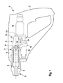
- a hand tool machine is in Fig. 1 schematized a hammer drill 1 shown, which has at its opposite the handle 2 tool side working end 3 a driven member 4 associated tool holder.
- the output member 4 is formed by a hammer tube 5, which receives an oscillating, in particular reciprocally driven oscillating hammer piston 6 at the rear and which is supported at its remote from the tool holder end via a bearing 7 on the neck 8 of an intermediate flange 9.
- the intermediate flange 9 has a base plate 10 which is connected to the output-side end plate 11 of the electric motor 12 provided as drive, whose output shaft 13 drives an intermediate shaft 14.
- the intermediate shaft 14 carries a wobble bearing 16 via a wobble bearing 15, which engages the neck 8 of the intermediate flange 9 by passing the hammer piston 6.
- annular neck 8 according to Fig. 2 recessed over at least a substantial part of its length via a ring sector 17, said recess also extends over the region of the bearing 7, which is provided on the base plate 10 of the intermediate flange 9 opposite end of the neck 8.
- this bearing 7 is provided by a provided on the neck 8 and the neck 8 outwardly stepped bearing receptacle 18 into which a bearing ring 19 is inserted, wherein in the illustration Fig. 2 the recessed ring sector 17 is shown running through the neck 8 and the bearing 7 at substantially the same course.
- the recess of the annular sector 17 corresponding circumferential portion conventionally be formed during manufacture, for example in the die-casting process. But it is also possible to separate out of the initially closed neck 8 of the intermediate flange 9 subsequently a the Schwarzestden ring sector 17 corresponding peripheral portion, in particular lymphzus or break out.
- bearing retainer 18 of the bearing ring 19 is axially inserted, as a closed bearing ring whose overlapping to the recessed peripheral portion of the bearing seat 18 peripheral portion 22 via separation points, in particular predetermined breaking points 20, is delimited as they relate on a closed bearing ring in Fig. 3 to 7 are illustrated.
- the researchersparende ring sector 17 of the bearing ring 19 is formed by a peripheral portion 22 which is delimited by wedge-shaped notches 21 and which is break out.
- the bearing ring 19, which may have like the bearing seat circular or oval shape is first inserted into the bearing receptacle 18 in a closed ring shape and arrangement of the considered sermonden peripheral portion 22 in coverage to the recessed annular sector 17 of the bearing ring 18, preferably matching, so that for the bearing ring 19 is given a form-bearing support which is absent only in the area of researcherêtden ring sector 17, and the peripheral portion 22 of the bearing ring 19 along the predetermined breaking points 20 broken and can be released from the ring composite, without the bearing ring 19 characterized in its dimensional stability is impaired.
- Fig. 3 to 5 illustrate the formation of the intended as separation points predetermined breaking points 20 as acute-angled notches 21, as in particular the enlarged view according to Fig. 5 shows, wherein in the notch base based on the closed, corresponding in the peripheral shape of the bearing seat 19 bearing ring 19 only a relatively small wall thickness remains.
- the notch angle is as shown in Fig. 4 preferably at about 60 to 80 °.
- the recess of the respective particular wedge-shaped notch 21 opposite circumferential region are provided with a thickening 23, so that in the region of the notches 21 is first given by the thickening 23 one of the other wall thickness of the bearing ring 19 corresponding wall cross-section.
- the required for insertion into the bearing receptacle 18 removal of the thickening 23 can be removed below, for example by grinding, turning over or the like, so that in this production given embodiment of the still closed bearing ring 19 after removal of the thickening 23 of the use of the bearing ring 19 in the bearing seat 18th as described above can be done.
- Such a rotation can also in other ways, for example according to Fig. 7 are achieved by end-side recesses 24 on the bearing ring 19, to which corresponding counterparts are provided on the bearing seat, which are not shown.
Landscapes
- Engineering & Computer Science (AREA)
- Mechanical Engineering (AREA)
- General Engineering & Computer Science (AREA)
- Rolling Contact Bearings (AREA)
- Mounting Of Bearings Or Others (AREA)
- Snaps, Bayonet Connections, Set Pins, And Snap Rings (AREA)
Description
- Die Erfindung betrifft eine Handwerkzeugmaschine gemäß dem Oberbegriff des Anspruches 1.
- Handwerkzeugmaschinen der vorgenannten Art mit einem Abtriebsglied, das in einem Lagerring geführt ist, welcher in einer ringförmigen, umschließenden Lageraufnahme angeordnet ist, sind aus der Praxis bekannt. Der den Lagerring umschließende Teil der Lageraufnahme ist durch das freie Ende eines vom Abtriebsglied durchsetzten Halses eines Zwischenflansches gebildet. Ein radialer Zugriff auf das Abtriebsglied, sei es zum Antrieb und/oder in Verbindung mit der Montage, ist infolge der geschlossenen Ausbildung von Lagerring und Lageraufnahme lediglich außerhalb des Bereiches der Lageraufnahme möglich. Dies beeinträchtigt die Montagemöglichkeiten sowie die Möglichkeiten für den antriebsseitigen Zugriff auf das Abtriebsglied und setzt für den Zwischenflansch bei Positionierung des Antriebszugriffes im Bereich des Zwischenflansches eine entsprechende Baulänge voraus.
-
DE 198 01 986 A1 offenbart eine Handwerkzeugmaschine mit den Merkmalen des Oberbegriffs des Anspruchs 1. - Der Erfindung liegt, bezogen auf eine Handwerkzeugmaschine der eingangs genannten Art, die Aufgabe zugrunde, die Zugriffsmöglichkeiten auf das Abtriebsglied zu erweitern, ohne damit die Montage des Lagerringes in der Lageraufnahme zu erschweren und/oder die Führungsqualität des Lagerringes für das Abtriebsglied zu beeinträchtigen.
- Gemäß der Erfindung wird dies bei einer Handwerkzeugmaschine gemäß dem Anspruch 1 erreicht.
- Bei der erfindungsgemäßen Handwerkzeugmaschine sind die Lageraufnahme und der Lagerring in offener Ringform mit in Überdeckung zueinander liegenden, ausgesparten Ringsektoren ausgebildet und es ist der ausgesparte Ringsektor des Lagerringes dadurch gebildet, dass aus dem Lagerring ein über als Soll-Bruchstellen ausgebildeten Trennstellen abgegrenzter Umfangsabschnitt herausgetrennt, insbesondere herausgebrochen ist.
- Diese Ausbildung des Lagerringes macht es möglich, diesen als geschlossenen Lagerring nicht nur herzustellen, sondern auch passend in die umgreifende, kreis- oder ovalringförmige Lageraufnahme einzusetzen, so dass der Lagerring, ungeachtet herstellungs- und/oder materialbedingter Eigenspannungen, zum Einsetzen in die Lageraufnahme in seiner Sollform vorliegt und aufgrund der Abstützung in der Lageraufnahme die herstellungsgegebene und auf die formhaltige Abstützung in der Lageraufnahme ausgelegte Form auch beibehält, wenn durch Entfernen, insbesondere Herausbrechen des über vorgegebene Trennstellen, insbesondere Soll-Bruchstellen, abgegrenzten Umfangsabschnittes die offene Ringform hergestellt wird.
- Damit sind für die Montage die gleichen Voraussetzungen gegeben wie bei einem geschlossenen Lagerring und, entsprechend abgestimmte Maßverhältnisse vorausgesetzt, kann der Lagerring entsprechend den jeweils gegebenen Passungen in die Lageraufnahme behinderungsfrei eingesetzt werden. Etwaige material- oder herstellungsbedingte Eigenspannungen im Lagerring, die bei offener Ringform zu Abweichungen von der vorgegebenen Sollform führen können, bleiben somit auf die Montage ohne Auswirkung und kommen letztlich auch nach dem Herausbrechen des über die Soll-Bruchstellen abgegrenzten Umfangsabschnittes in die Führungsqualität des Lagerringes für das Abtriebsglied beeinträchtigendem Maße nicht zum Tragen, da die Lageraufnahme für den nunmehr offenen Lagerring eine formhaltige Abstützung bildet, die gegebenenfalls auch zur formschlüssigen Verankerung des Lagerringes in der Lageraufnahme hinreichend ist. Für eine solche Verankerung, insbesondere eine drehfeste Festlegung des Lagerringes, können gegebenenfalls auch zusätzlich, bevorzugt stirnseitig auch Nuten vorgesehen sein, die mit entsprechenden, seitens der Lageraufnahme vorgesehenen Gegenstücken die erforderliche Fixierung, gegebenenfalls auch axiale Positionierung des Lagerringes sicherstellen.
- Das Montageverfahren ist insbesondere für Lagerringe zweckmäßig, die, bevorzugt als Gleitlagerringe, aus spröden, vor allem sprödbrechenden Materialien bestehen. In Frage kommen als solche Materialien insbesondere Sintermaterialien oder andere zu Sprödbruch neigende Materialien, bei denen sich in der Herstellung gegebenenfalls auch Eigenspannungen ergeben, die im aufgebrochenen Zustand des Lagerringes Abweichungen von der Sollform zur Folge haben können.
- Die Soll-Bruchstellen können im Rahmen der Erfindung durch im Innen- und/oder Außenumfang des Lagerrings vorgesehene Kerben, gegebenenfalls in Überdeckung zueinander liegende Kerben gebildet sein, so dass nur vergleichsweise dünne Stege verbleiben.
- In Verbindung mit einseitig, insbesondere innenseitig vorgesehenen Kerben kann es zweckmäßig sein, im Überdeckungsbereich zur jeweiligen Kerbe am Außenumfang des Lagerringes eine Aufdickung vorzusehen, um bei der Herstellung ungeachtet der Einkerbung einen durchlaufend im Wesentlichen gleichbleibenden Materialquerschnitt zu erreichen. Die Aufdickung lässt sich im Anschluss an die Herstellung, also zum Beispiel im Anschluss an die Verpressung bei Sintermaterialien, durch Schleifen, Überdrehen oder dergleichen Bearbeitungsverfahren in einfacher Weise abtragen.
- In Bezug auf die Verdrehsicherung des Lagerringes kann es zweckmäßig sein, diesen auch mit stirnseitigen Einkerbungen zu versehen, denen an der jeweiligen Lageraufnahme entsprechende Gegenstücke zugeordnet sind.
- Weitere Vorteile und zweckmäßige Ausführungen sind den Ansprüchen, der Figurenbeschreibung und den Zeichnungen zu entnehmen. Es zeigen:
- Fig. 1
- als Beispiel einer erfindungsgemäß ausgestalteten Handwerkzeugmaschine einen Bohrhammer in vereinfachter Darstellung,
- Fig. 2
- in perspektivischer Darstellung einen Zwischenflansch des Bohrhammers, der auslaufend auf sein werkzeugseitiges Ende eine Lagerung mit einer Lageraufnahme für einen Lagerring aufweist, der das mit dem Werkzeug zu verbindende Abtriebsglied führt,
- Fig. 3 und 4
- Darstellungen des Lagerrings in Perspektive und stirnseitiger Ansicht,
- Fig. 5
- eine vergrößerte Darstellung des Ausschnittes V in
Fig. 4 , - Fig. 6
- eine vergrößerte Teildarstellung eines Lagerringes in Draufsicht, bei der ein innenseitig angekerbter Bereich des Lagerrings außenseitig aufgedickt ist, und
- Fig. 7
- eine weitere perspektivische Darstellung eines Lagerrings.
- Als Handwerkzeugmaschine ist in
Fig. 1 schematisiert ein Bohrhammer 1 dargestellt, der an seinem dem Handgriff 2 gegenüberliegenden werkzeugseitigen Arbeitsende 3 eine einem Abtriebsglied 4 zugeordnete Werkzeugaufnahme aufweist. Das Abtriebsglied 4 ist durch ein Hammerrohr 5 gebildet, das rückseitig zur Werkstückaufnahme einen oszillierend, insbesondere hubbeweglich oszillierend angetriebenen Hammerkolben 6 aufnimmt und das an seinem von der Werkzeugaufnahme abgelegenen Ende über eine Lagerstelle 7 am Hals 8 eines Zwischenflansches 9 abgestützt ist. Der Zwischenflansch 9 weist eine Fußplatte 10 auf, die mit der abtriebsseitigen Stirnplatte 11 des als Antrieb vorgesehenen E-Motores 12 verbunden ist, dessen Abtriebswelle 13 eine Zwischenwelle 14 antreibt. Die Zwischenwelle 14 trägt über ein Taumellager 15 einen Taumelfinger 16, der den Hals 8 des Zwischenflansches 9 durchgreifend am Hammerkolben 6 angreift. Entsprechend der Taumelbewegung, also der Hub-Schwenkbewegung des Taumelfingers 16 ist der vom Taumelfinger 16 durchgriffene, ringförmige Hals 8 gemäßFig. 2 zumindest über einen wesentlichen Teil seiner Länge über einen Ringsektor 17 ausgespart, wobei diese Aussparung sich auch über den Bereich der Lagerstelle 7 erstreckt, die am zur Fußplatte 10 des Zwischenflansches 9 gegenüberliegenden Ende des Halses 8 vorgesehen ist. Gebildet ist diese Lagerstelle 7 durch eine am Hals 8 vorgesehene und zum Hals 8 nach außen stufig abgesetzte Lageraufnahme 18, in die ein Lagerring 19 eingesetzt ist, wobei in der Darstellung gemäßFig. 2 der ausgesparte Ringsektor 17 über den Hals 8 und die Lagerstelle 7 bei im Wesentlichen gleichem Verlauf durchlaufend dargestellt ist. - Bezogen auf den Zwischenflansch 9 kann die Aussparung des dem Ringsektor 17 entsprechenden Umfangsabschnittes herkömmlicherweise bei der Herstellung, zum Beispiel im Druckgussverfahren, ausgebildet werden. Es ist aber auch möglich, aus dem zunächst geschlossen hergestellten Hals 8 des Zwischenflansches 9 nachträglich einen dem auszusparenden Ringsektor 17 entsprechenden Umfangsabschnitt herauszutrennen, insbesondere herauszuarbeiten oder herauszubrechen.
- In die über den ausgesparten Ringsektor 17 geöffnete Lageraufnahme 18 wird der Lagerring 19 axial eingesetzt, und zwar als geschlossener Lagerring, dessen in Überdeckung zum ausgesparten Umfangsabschnitt der Lageraufnahme 18 liegender Umfangsabschnitt 22 über Trennstellen, insbesondere Soll-Bruchstellen 20, abgegrenzt ist, wie sie bezogen auf einen geschlossenen Lagerring in
Fig. 3 bis 7 veranschaulicht sind. In der Darstellung gemäßFig. 3 ist der auszusparende Ringsektor 17 des Lagerrings 19 durch einen Umfangsabschnitt 22 gebildet, der über keilförmige Kerben 21 abgegrenzt ist und der herauszubrechen ist. - Der Lagerring 19, der wie die Lageraufnahme Kreis- oder Ovalform aufweisen kann, wird zunächst in die Lageraufnahme 18 in geschlossener Ringform und bei Anordnung des auszubrechenden Umfangsabschnittes 22 in Überdeckung zum ausgesparten Ringsektor 17 des Lagerringes 18 eingesetzt, und zwar bevorzugt passend, so dass für den Lagerring 19 eine formhaltige Abstützung gegeben ist, die lediglich im Bereich des auszusparenden Ringsektors 17 fehlt, und der Umfangsabschnitt 22 des Lagerringes 19 entlang der Soll-Bruchstellen 20 ausgebrochen und aus dem Ringverbund gelöst werden kann, ohne dass der Lagerring 19 dadurch in seiner Formhaltigkeit beeinträchtigt wird.
- Die
Fig. 3 bis 5 veranschaulichen die Ausbildung der als Trennstellen vorgesehenen Soll-Bruchstellen 20 als spitzwinklige Kerben 21, wie insbesondere die vergrößerte Darstellung gemäßFig. 5 zeigt, wobei im Kerbgrund bezogen auf den geschlossenen, in der Umfangsform der Lageraufnahme 19 entsprechenden Lagerring 19 lediglich eine verhältnismäßig geringe Wandstärke verbleibt. Der Kerbwinkel liegt gemäß der Darstellung inFig. 4 bevorzugt bei etwa 60 bis 80°. Soweit eine solche Ausgestaltung der Soll-Bruchstellen 20 durch die Wandstärke des Lagerringes 19 wesentlich schwächende keilförmige Kerben 21 oder auch rinnenförmig verrundete oder nutförmig eckige Vertiefungen bei der Fertigung des Lagerringes 19 zu Schwierigkeiten führt, was insbesondere beim Gießen oder auch Sintern des Lagerringes 19 der Fall sein kann, kann erfindungsgemäß, wie inFig. 6 gezeigt, der der Vertiefung der jeweiligen insbesondere keilförmigen Kerbe 21 gegenüberliegende Umfangsbereich mit einer Aufdickung 23 versehen werden, so dass auch im Bereich der Kerben 21 zunächst durch die Aufdickung 23 ein der sonstigen Wandstärke des Lagerringes 19 entsprechender Wandquerschnitt gegeben ist. Die zum Einsetzen in die Lageraufnahme 18 erforderliche Entfernung der Aufdickung 23 kann nachfolgend abgetragen werden, beispielsweise durch Schleifen, Überdrehen oder dergleichen, so dass bei dieser fertigungsgegebenen Ausgestaltung des noch geschlossenen Lagerringes 19 nach Abtragen der Aufdickung 23 der Einsatz des Lagerringes 19 in die Lageraufnahme 18 wie vor geschildert erfolgen kann. - Grundsätzlich besteht auch die Möglichkeit, die Aufdickung 23 lediglich im zum auszubrechenden Umfangsbereich überdeckenden Bereich abzutragen und so im Übergang auf den ausgesparten Umfangsbereich 22 am Lagerring 19 Vorsprünge auszubilden, die durch radialen Übergriff oder Eingriff in die Lageraufnahme 18 eine Verdrehsicherung des Lagerringes 19 gewährleisten.
- Eine solche Verdrehsicherung kann auch in anderer Weise, zum Beispiel gemäß
Fig. 7 durch stirnseitige Aussparungen 24 am Lagerring 19 erreicht werden, zu denen korrespondierende Gegenstücke an der Lageraufnahme vorgesehen werden, die nicht gezeigt sind.
Claims (11)
- Handwerkzeugmaschine, insbesondere ein Meißel- und/oder Bohrhammer, mit einem ein Werkzeug aufnehmenden Abtriebsglied (4), das in einem Lagerring (19) geführt ist, welcher in einer umgreifenden Lageraufnahme (18) angeordnet ist, dadurch gekennzeichnet, dass die Lageraufnahme (18) und der Lagerring (19) in offener Ringform mit in Überdeckung zueinander liegenden, ausgesparten Ringsektoren (17) ausgebildet sind und dass ein Umfangsabschnitt (22) des Lagerringes (19), der durch als Soll-Bruchstellen (20) ausgebildete Trennstellen abgegrenzt und herausgetrennt ist, dessen ausgesparten Ringsektor (17) bildet.
- Handwerkzeugmaschine nach Anspruch 1, dadurch gekennzeichnet, dass der offene Lagerring (19) formhaltend von der kreisförmigen oder ovalen Lageraufnahme (18) aufgenommen ist.
- Handwerkzeugmaschine nach Anspruch 1 oder 2, dadurch gekennzeichnet, dass der offene Lagerring (19) passend, insbesondere formschlüssig, in der Lageraufnahme (18) gehalten ist.
- Handwerkzeugmaschine nach Anspruch 1, dadurch gekennzeichnet, dass die Soll-Bruchstellen (20) durch im Innen- und/oder Außenumfang des Lagerringes (19) vorgesehene Kerben (21) gebildet sind.
- Handwerkzeugmaschine nach Anspruch 4, dadurch gekennzeichnet, dass die im Innen- und Außenumfang des Lagerringes (19) vorgesehenen Kerben (21) einander gegenüberliegend, insbesondere einander symmetrisch gegenüberliegend angeordnet sind.
- Handwerkzeugmaschine nach Anspruch 5, dadurch gekennzeichnet, dass der Lagerring (19) im Überdeckungsbereich zu zumindest einer seiner am Innenumfang vorgesehenen Kerben (21) außenseitig aufgedickt ist.
- Handwerkzeugmaschine nach Anspruch 6, dadurch gekennzeichnet, dass die Aufdickung (23) im Konturverlauf der Kontur der Kerbe (21) folgt.
- Handwerkzeugmaschine nach Anspruch 7, dadurch gekennzeichnet, dass die Wandstärke des Lagerringes (19) im Bereich der Kerbe (21) durch die zur Kerbe 21 überdeckend liegende Aufdickung (23) in Annäherung gleich ist.
- Handwerkzeugmaschine nach einem der Ansprüch 4 bis 8, dadurch gekennzeichnet, dass die Kerben (21) als Winkelnuten, insbesondere spitzwinklige Winkelnuten, ausgebildet sind.
- Handwerkzeugmaschine nach einem der Anspruch 4 bis 9, dadurch gekennzeichnet, dass der Lagerring (19) zur drehsicheren Anordnung in einer Lageraufnahme (18) mit stirnseitigen Aussparungen (24), insbesondere Nuten, versehen ist.
- Handwerkzeugmaschine nach einem der Ansprüche 4 bis 10, dadurch gekennzeichnet, dass der Lagerring (19) aus sprödbrechenden Materialien besteht, insbesondere durch einen Sintermetallkörper, gebildet ist.
Applications Claiming Priority (2)
| Application Number | Priority Date | Filing Date | Title |
|---|---|---|---|
| DE102007057453A DE102007057453A1 (de) | 2007-11-29 | 2007-11-29 | Handwerkzeugmaschine |
| PCT/EP2008/063024 WO2009068344A1 (de) | 2007-11-29 | 2008-09-29 | Handwerkzeugmaschine |
Publications (2)
| Publication Number | Publication Date |
|---|---|
| EP2225071A1 EP2225071A1 (de) | 2010-09-08 |
| EP2225071B1 true EP2225071B1 (de) | 2014-11-26 |
Family
ID=40251875
Family Applications (1)
| Application Number | Title | Priority Date | Filing Date |
|---|---|---|---|
| EP08854209.7A Active EP2225071B1 (de) | 2007-11-29 | 2008-09-29 | Handwerkzeugmaschine |
Country Status (6)
| Country | Link |
|---|---|
| US (2) | US8561714B2 (de) |
| EP (1) | EP2225071B1 (de) |
| CN (1) | CN101878095B (de) |
| DE (1) | DE102007057453A1 (de) |
| RU (1) | RU2497655C2 (de) |
| WO (1) | WO2009068344A1 (de) |
Families Citing this family (12)
| Publication number | Priority date | Publication date | Assignee | Title |
|---|---|---|---|---|
| DE102007014758A1 (de) * | 2007-03-28 | 2008-10-02 | Robert Bosch Gmbh | Handwerkzeugmaschine |
| US8636081B2 (en) | 2011-12-15 | 2014-01-28 | Milwaukee Electric Tool Corporation | Rotary hammer |
| EP2556922B1 (de) * | 2011-08-09 | 2014-03-19 | C. & E. Fein GmbH | Kraftgetriebenes Handwerkzeug |
| DE102012104538A1 (de) * | 2012-05-25 | 2013-11-28 | Gustav Klauke Gmbh | Werkzeug |
| US11085502B2 (en) | 2017-08-28 | 2021-08-10 | Qa1 Precision Products, Inc. | Bleed needle for a hydraulic system |
| USD866408S1 (en) | 2017-08-28 | 2019-11-12 | Qa1 Precision Products, Inc. | Shock absorber |
| USD869259S1 (en) | 2017-08-28 | 2019-12-10 | Qa1 Precision Products, Inc. | Valve component |
| USD872837S1 (en) | 2017-08-28 | 2020-01-14 | Qa1 Precision Products, Inc. | Bleed needle |
| US11105390B2 (en) | 2017-08-28 | 2021-08-31 | Qa1 Precision Products, Inc. | Shock absorber with dry valving |
| US11945087B2 (en) | 2019-03-29 | 2024-04-02 | Tien-I Industrial Co., Ltd. | Impact tool head |
| US20240009743A1 (en) * | 2020-11-19 | 2024-01-11 | Milwaukee Electric Tool Corporation | Hole saw and method of manufacturing a hole saw |
| DE102024202093A1 (de) | 2024-03-06 | 2025-09-11 | Robert Bosch Gesellschaft mit beschränkter Haftung | Handwerkzeugmaschine mit einem Schlagwerk |
Family Cites Families (67)
| Publication number | Priority date | Publication date | Assignee | Title |
|---|---|---|---|---|
| US1350245A (en) * | 1919-11-28 | 1920-08-17 | Joseph F Stachowski | Bearing |
| US2768036A (en) * | 1955-11-14 | 1956-10-23 | Cleveland Pneumatic Tool Co | Sectional fluid seal |
| US3393441A (en) * | 1965-09-29 | 1968-07-23 | Adrian J. Gebhart | Apparatus for moving bearings to and from press-fit relation on shafts |
| US3787059A (en) * | 1972-08-14 | 1974-01-22 | Ramsey Corp | Piston ring end guide |
| US3810639A (en) * | 1972-08-31 | 1974-05-14 | Parker Hannifin Corp | Frangible backup ring for sealing rings |
| US4157675A (en) * | 1975-01-17 | 1979-06-12 | King John O Jr | Filled breakneck fastener |
| DE2512253C3 (de) * | 1975-03-20 | 1978-10-19 | Itw-Ateco Gmbh, 2000 Norderstedt | Gelenkpfanne für ein Winkelgelenk |
| US4028784A (en) * | 1975-07-07 | 1977-06-14 | Ford Motor Company | Preloaded tie rod end assembly |
| US3988818A (en) * | 1975-07-07 | 1976-11-02 | Ford Motor Company | Tie rod end |
| US4016950A (en) * | 1975-07-07 | 1977-04-12 | Ford Motor Company | Suspension arm and joint assembly |
| NL182503C (nl) * | 1976-11-01 | 1988-03-16 | Lely Nv C Van Der | Automatische breekpenkoppeling. |
| US4129921A (en) * | 1978-01-05 | 1978-12-19 | Shepherd Products U.S. Inc. | Plastic grip ring |
| US4240682A (en) * | 1979-03-15 | 1980-12-23 | The Torrington Company | Bearing race |
| SU920188A1 (ru) * | 1979-09-26 | 1982-04-15 | За витель t | Опора бурового шарошечного долота |
| US4293170A (en) * | 1979-11-21 | 1981-10-06 | General Electric Company | Thrust bearing assembly |
| US4278180A (en) * | 1980-01-24 | 1981-07-14 | Aluminum Company Of America | Container closure with breakable annular ring |
| DE3138632A1 (de) * | 1981-09-29 | 1983-04-14 | FAG Kugelfischer Georg Schäfer & Co, 8720 Schweinfurt | Verfahren zum brechen von ringen, insbesondere waelzlagerringen |
| GB2165318B (en) * | 1984-10-02 | 1988-07-20 | Rhp Group Plc | Bearing ring and method of making same |
| US4784438A (en) * | 1986-02-20 | 1988-11-15 | Fikse Tyman H | Tunneling machine rotatable member |
| US4779638A (en) * | 1987-10-13 | 1988-10-25 | Helix Enterprises, Inc. | Breakaway swivel coupling |
| US4837915A (en) * | 1988-01-04 | 1989-06-13 | James D. Welch | Method of breaking bearings |
| US4932814A (en) * | 1989-07-24 | 1990-06-12 | York Ronald A | Portable line boring machine |
| US5104008A (en) * | 1990-12-03 | 1992-04-14 | Northern Engineering And Plastics Corp. | Resealable bottle cap with push-pull closure |
| DE4100186A1 (de) * | 1991-01-05 | 1992-07-09 | Bosch Gmbh Robert | Handwerkzeugmaschine mit abnehmbaren werkzeughalter |
| US5222963A (en) * | 1991-01-17 | 1993-06-29 | Ethicon, Inc. | Pull-through circular anastomosic intraluminal stapler with absorbable fastener means |
| US5284285A (en) * | 1992-03-13 | 1994-02-08 | Precision Handling Devices | Bearing assembly and web feed device incorporating same |
| DE4240848C1 (de) * | 1992-12-04 | 1994-04-21 | Aeroquip Gmbh | Rohr- oder Schlauchleitung zum Transport eines Fluids |
| AU6673094A (en) * | 1993-05-12 | 1994-12-12 | Fuelmaker Corporation | Split-ring breakaway connector |
| GB9317530D0 (en) * | 1993-08-21 | 1993-10-06 | Westland Helicopters | Fusible support devices for rotating shafts |
| US5603592A (en) * | 1994-10-03 | 1997-02-18 | Huck International, Inc. | High strength blind bolt with uniform high clamp over an extended grip range |
| US5775834A (en) * | 1995-08-14 | 1998-07-07 | Jackson; Brian G. | Portable highway warning device with frangible retainer ring |
| US5791212A (en) * | 1996-06-21 | 1998-08-11 | Han; Ki Su | Fastener holding device |
| US6082233A (en) * | 1996-06-21 | 2000-07-04 | Han; Ki Su | Fastener holding device |
| US5941360A (en) * | 1996-11-21 | 1999-08-24 | Snap-On Technologies, Inc. | Impulse wrench with wrap spring clutch assembly |
| DE19710868A1 (de) * | 1997-03-15 | 1998-09-17 | Schaeffler Waelzlager Ohg | Axiallagerscheibe |
| JP3582760B2 (ja) * | 1997-04-18 | 2004-10-27 | 日立工機株式会社 | ハンマドリル |
| US6601749B2 (en) * | 1998-06-19 | 2003-08-05 | Scimed Life Systems, Inc. | Multi fire full thickness resectioning device |
| US6217222B1 (en) * | 1998-11-18 | 2001-04-17 | Skf Usa Inc. | Notching construction and method |
| US6146471A (en) * | 1999-04-08 | 2000-11-14 | Roller Bearing Company Of America | Spherical plain bearing and method of manufacturing thereof |
| US6312215B1 (en) * | 2000-02-15 | 2001-11-06 | United Technologies Corporation | Turbine engine windmilling brake |
| US6585691B1 (en) * | 2001-05-11 | 2003-07-01 | Jonathan J. Vitello | Tamper evident end cap assembly for a loaded syringe and process |
| US7410084B1 (en) * | 2001-08-31 | 2008-08-12 | Reed Daniel J | Multiple-impact adapter for a hammer tool |
| WO2003035321A2 (en) * | 2001-10-26 | 2003-05-01 | Black & Decker Inc. | Drilling and/or hammering tool |
| DE10152959B4 (de) * | 2001-10-26 | 2007-03-15 | Robert Bosch Gmbh | Handwerkzeugmaschine |
| US6819017B2 (en) * | 2002-01-02 | 2004-11-16 | Intel Corporation | Method and apparatus for fan redundancy |
| US20040130106A1 (en) * | 2002-01-25 | 2004-07-08 | Dembicks Tyler J | Power tool chuck and tool bit shank |
| DE10202977C1 (de) * | 2002-01-26 | 2003-10-30 | Mtu Aero Engines Gmbh | Drehlagerung mit einer Sollbruchstelle |
| US6588447B1 (en) * | 2002-07-09 | 2003-07-08 | Arthur A. Hendey | Break-away water meter register retaining ring |
| DE10242738A1 (de) * | 2002-09-13 | 2005-01-20 | Robert Bosch Gmbh | Handwekzeugmaschine, insbesondere Winkelschleifmaschine |
| US6824491B2 (en) * | 2003-03-25 | 2004-11-30 | Power Network Industry Co., Ltd. | Power transmission device with automatic speed switching mechanism |
| US20040194504A1 (en) * | 2003-04-01 | 2004-10-07 | Edwards Melody Jan | Break away ring |
| KR101148516B1 (ko) * | 2003-11-13 | 2012-05-21 | 페더럴-모걸 코오포레이숀 | 트러스트 와셔 및 그 제조방법 |
| US7510195B2 (en) * | 2003-11-21 | 2009-03-31 | Honeywell International Inc. | High temperature and high pressure compressor piston ring |
| DE102004036585A1 (de) * | 2004-07-28 | 2006-03-23 | Robert Bosch Gmbh | Zwischenflansch für eine Werkzeugmaschine |
| FR2873780B1 (fr) * | 2004-07-29 | 2006-09-08 | Comap Sa | Bague de visualisation du sertissage d'un raccord pour tubes |
| US7698979B2 (en) * | 2004-09-22 | 2010-04-20 | Amada Tool America, Inc. | Biasing assembly for a punching device |
| US7481608B2 (en) * | 2005-04-27 | 2009-01-27 | Eastway Fair Company Limited | Rotatable chuck |
| US20060267355A1 (en) * | 2005-05-31 | 2006-11-30 | Stachowiak John E Jr | Locking apparatus and method |
| DE102005026614A1 (de) | 2005-06-09 | 2006-12-14 | Zf Friedrichshafen Ag | Einrichtung zur axialen Sicherung der Lager und der Wellen des Variators eines stufenlosen Automatgetriebes und zur Abstützung der bei der Variatorverstellung auftretenden axialen Kräfte |
| US7648764B2 (en) * | 2005-06-30 | 2010-01-19 | Uchicago Argonne, Llc | Two-piece container seal and method of manufacture |
| GB2438075C (en) * | 2006-05-10 | 2008-12-24 | Roller Bearing Co Of America | Bearing arrangement for an axle mount of an articulated vehicle |
| DE102007014758A1 (de) * | 2007-03-28 | 2008-10-02 | Robert Bosch Gmbh | Handwerkzeugmaschine |
| GB2463066A (en) * | 2008-09-01 | 2010-03-03 | Biomet Uk Ltd | A prosthetic bearing component |
| GB2469669A (en) * | 2009-04-23 | 2010-10-27 | Edward Docherty Scott | Frangible ceramic bearing |
| US8070504B2 (en) * | 2009-06-17 | 2011-12-06 | John Mezzalingua Associates, Inc. | Coaxial cable port locking terminator and method of use thereof |
| DE102009027570A1 (de) * | 2009-07-09 | 2011-01-13 | Robert Bosch Gmbh | Vorrichtung zum Positionieren und Befestigen einer Einrichtung, insbesondere eines Handgriffs an einem Elektrowerkzeug |
| JP5456555B2 (ja) * | 2010-04-23 | 2014-04-02 | 株式会社マキタ | 電動工具 |
-
2007
- 2007-11-29 DE DE102007057453A patent/DE102007057453A1/de not_active Withdrawn
-
2008
- 2008-09-29 EP EP08854209.7A patent/EP2225071B1/de active Active
- 2008-09-29 CN CN2008801183430A patent/CN101878095B/zh active Active
- 2008-09-29 RU RU2010126060/02A patent/RU2497655C2/ru not_active IP Right Cessation
- 2008-09-29 WO PCT/EP2008/063024 patent/WO2009068344A1/de not_active Ceased
- 2008-09-29 US US12/745,422 patent/US8561714B2/en not_active Expired - Fee Related
-
2013
- 2013-10-22 US US14/060,265 patent/US20140041889A1/en not_active Abandoned
Also Published As
| Publication number | Publication date |
|---|---|
| WO2009068344A1 (de) | 2009-06-04 |
| CN101878095B (zh) | 2012-11-28 |
| US8561714B2 (en) | 2013-10-22 |
| US20100300715A1 (en) | 2010-12-02 |
| EP2225071A1 (de) | 2010-09-08 |
| RU2010126060A (ru) | 2012-01-10 |
| CN101878095A (zh) | 2010-11-03 |
| US20140041889A1 (en) | 2014-02-13 |
| RU2497655C2 (ru) | 2013-11-10 |
| DE102007057453A1 (de) | 2009-06-04 |
Similar Documents
| Publication | Publication Date | Title |
|---|---|---|
| WO2009068344A1 (de) | Handwerkzeugmaschine | |
| EP3113894B1 (de) | Werkzeugvorrichtung mit einem bauteil zur herstellung einer formschlüssigen nietverbindung | |
| EP2028299B1 (de) | Auflösewalze mit Clipverbindung | |
| DE102013207573A1 (de) | Lagerrahmen oder Zylinderkopfhaube | |
| DE102017104159B4 (de) | Zahnrad für eine Ausgleichswelle und eine Ausgleichswelle | |
| EP1636474B1 (de) | Verfahren zur herstellung eines einteiligen kolbens für einen verbrennungsmotor | |
| DE102005019501A1 (de) | Verfahren zum Lagern einer Welle sowie Lageranordnung | |
| DE102008013227A1 (de) | Verfahren zum Herstellen einer Verbindung zwischen einer Welle und einem Hülsenabschnitt | |
| DE102016201617A1 (de) | Kolben einer Brennkraftmaschine | |
| DE19733566A1 (de) | Spindelmotor mit Hülse | |
| DE102014206977A1 (de) | Gewichtsoptimierter Planetenträger | |
| DE10359854A1 (de) | Zylinderkopfbohrer mit Hartmetallschneiden und Kunststoffschaft | |
| EP0170877B1 (de) | Offenend-Spinnrotor und Verfahren zu seiner Herstellung | |
| DE2939325A1 (de) | Aus einem grundkoerper und einem rotorkoerper bestehender offenend-spinnrotor | |
| DE102013226449B4 (de) | Spanlos gefertigte Ölkanäle in einem geteilten Rotor für einen hydraulischen Nockenwellenversteller | |
| DE3344467C2 (de) | ||
| EP1373744B1 (de) | Lageranordnung sowie elektroantrieb mit einer solchen lageranordnung | |
| DE102007007890A1 (de) | Verbindung von einer Innenwelle mit einer Aussenhülse bzw. einer Aussenwelle mit einer Innenhülse | |
| DE102008041890A1 (de) | Koppelbolzen, Werkzeugmaschine und Herstellverfahren für einen Koppelbolzen | |
| DE10256060B4 (de) | Verfahren zur Herstellung eines Bohrgewindefräsers und danach hergestellter Bohrgewindefräser | |
| EP4089284B1 (de) | Nassläuferpumpe | |
| DE102019122853A1 (de) | Drehmomentübertragungsbestandteil mit ringförmiger Aufnahmerille zur Positionierung einer Ausgleichsmasse; Elektromotor sowie Auswuchtverfahren | |
| DE102007018791B3 (de) | Segmentband für eine Bohrkrone und Bohrkrone | |
| DE19949554A1 (de) | Stanzstempel und Verfahren zu dessen Montage | |
| DE102007005182B3 (de) | Verfahren zur Befestigung eines einsatzgehärteten Antriebszapfens am gehärteten Schermesser einer Heckenschere |
Legal Events
| Date | Code | Title | Description |
|---|---|---|---|
| PUAI | Public reference made under article 153(3) epc to a published international application that has entered the european phase |
Free format text: ORIGINAL CODE: 0009012 |
|
| 17P | Request for examination filed |
Effective date: 20100629 |
|
| AK | Designated contracting states |
Kind code of ref document: A1 Designated state(s): AT BE BG CH CY CZ DE DK EE ES FI FR GB GR HR HU IE IS IT LI LT LU LV MC MT NL NO PL PT RO SE SI SK TR |
|
| AX | Request for extension of the european patent |
Extension state: AL BA MK RS |
|
| DAX | Request for extension of the european patent (deleted) | ||
| 17Q | First examination report despatched |
Effective date: 20130710 |
|
| RIC1 | Information provided on ipc code assigned before grant |
Ipc: F16C 33/14 20060101ALI20140630BHEP Ipc: F16C 35/02 20060101ALI20140630BHEP Ipc: B25D 17/06 20060101AFI20140630BHEP Ipc: B25D 11/06 20060101ALI20140630BHEP |
|
| GRAP | Despatch of communication of intention to grant a patent |
Free format text: ORIGINAL CODE: EPIDOSNIGR1 |
|
| INTG | Intention to grant announced |
Effective date: 20140827 |
|
| GRAS | Grant fee paid |
Free format text: ORIGINAL CODE: EPIDOSNIGR3 |
|
| GRAA | (expected) grant |
Free format text: ORIGINAL CODE: 0009210 |
|
| AK | Designated contracting states |
Kind code of ref document: B1 Designated state(s): AT BE BG CH CY CZ DE DK EE ES FI FR GB GR HR HU IE IS IT LI LT LU LV MC MT NL NO PL PT RO SE SI SK TR |
|
| REG | Reference to a national code |
Ref country code: GB Ref legal event code: FG4D Free format text: NOT ENGLISH |
|
| REG | Reference to a national code |
Ref country code: CH Ref legal event code: EP |
|
| REG | Reference to a national code |
Ref country code: AT Ref legal event code: REF Ref document number: 697900 Country of ref document: AT Kind code of ref document: T Effective date: 20141215 |
|
| REG | Reference to a national code |
Ref country code: IE Ref legal event code: FG4D Free format text: LANGUAGE OF EP DOCUMENT: GERMAN |
|
| REG | Reference to a national code |
Ref country code: DE Ref legal event code: R096 Ref document number: 502008012444 Country of ref document: DE Effective date: 20150108 |
|
| REG | Reference to a national code |
Ref country code: NL Ref legal event code: VDEP Effective date: 20141126 |
|
| REG | Reference to a national code |
Ref country code: LT Ref legal event code: MG4D |
|
| PG25 | Lapsed in a contracting state [announced via postgrant information from national office to epo] |
Ref country code: LT Free format text: LAPSE BECAUSE OF FAILURE TO SUBMIT A TRANSLATION OF THE DESCRIPTION OR TO PAY THE FEE WITHIN THE PRESCRIBED TIME-LIMIT Effective date: 20141126 Ref country code: ES Free format text: LAPSE BECAUSE OF FAILURE TO SUBMIT A TRANSLATION OF THE DESCRIPTION OR TO PAY THE FEE WITHIN THE PRESCRIBED TIME-LIMIT Effective date: 20141126 Ref country code: PT Free format text: LAPSE BECAUSE OF FAILURE TO SUBMIT A TRANSLATION OF THE DESCRIPTION OR TO PAY THE FEE WITHIN THE PRESCRIBED TIME-LIMIT Effective date: 20150326 Ref country code: IS Free format text: LAPSE BECAUSE OF FAILURE TO SUBMIT A TRANSLATION OF THE DESCRIPTION OR TO PAY THE FEE WITHIN THE PRESCRIBED TIME-LIMIT Effective date: 20150326 Ref country code: FI Free format text: LAPSE BECAUSE OF FAILURE TO SUBMIT A TRANSLATION OF THE DESCRIPTION OR TO PAY THE FEE WITHIN THE PRESCRIBED TIME-LIMIT Effective date: 20141126 Ref country code: NL Free format text: LAPSE BECAUSE OF FAILURE TO SUBMIT A TRANSLATION OF THE DESCRIPTION OR TO PAY THE FEE WITHIN THE PRESCRIBED TIME-LIMIT Effective date: 20141126 Ref country code: NO Free format text: LAPSE BECAUSE OF FAILURE TO SUBMIT A TRANSLATION OF THE DESCRIPTION OR TO PAY THE FEE WITHIN THE PRESCRIBED TIME-LIMIT Effective date: 20150226 |
|
| PG25 | Lapsed in a contracting state [announced via postgrant information from national office to epo] |
Ref country code: CY Free format text: LAPSE BECAUSE OF FAILURE TO SUBMIT A TRANSLATION OF THE DESCRIPTION OR TO PAY THE FEE WITHIN THE PRESCRIBED TIME-LIMIT Effective date: 20141126 Ref country code: SE Free format text: LAPSE BECAUSE OF FAILURE TO SUBMIT A TRANSLATION OF THE DESCRIPTION OR TO PAY THE FEE WITHIN THE PRESCRIBED TIME-LIMIT Effective date: 20141126 Ref country code: HR Free format text: LAPSE BECAUSE OF FAILURE TO SUBMIT A TRANSLATION OF THE DESCRIPTION OR TO PAY THE FEE WITHIN THE PRESCRIBED TIME-LIMIT Effective date: 20141126 Ref country code: GR Free format text: LAPSE BECAUSE OF FAILURE TO SUBMIT A TRANSLATION OF THE DESCRIPTION OR TO PAY THE FEE WITHIN THE PRESCRIBED TIME-LIMIT Effective date: 20150227 Ref country code: LV Free format text: LAPSE BECAUSE OF FAILURE TO SUBMIT A TRANSLATION OF THE DESCRIPTION OR TO PAY THE FEE WITHIN THE PRESCRIBED TIME-LIMIT Effective date: 20141126 |
|
| PG25 | Lapsed in a contracting state [announced via postgrant information from national office to epo] |
Ref country code: CZ Free format text: LAPSE BECAUSE OF FAILURE TO SUBMIT A TRANSLATION OF THE DESCRIPTION OR TO PAY THE FEE WITHIN THE PRESCRIBED TIME-LIMIT Effective date: 20141126 Ref country code: EE Free format text: LAPSE BECAUSE OF FAILURE TO SUBMIT A TRANSLATION OF THE DESCRIPTION OR TO PAY THE FEE WITHIN THE PRESCRIBED TIME-LIMIT Effective date: 20141126 Ref country code: RO Free format text: LAPSE BECAUSE OF FAILURE TO SUBMIT A TRANSLATION OF THE DESCRIPTION OR TO PAY THE FEE WITHIN THE PRESCRIBED TIME-LIMIT Effective date: 20141126 Ref country code: SK Free format text: LAPSE BECAUSE OF FAILURE TO SUBMIT A TRANSLATION OF THE DESCRIPTION OR TO PAY THE FEE WITHIN THE PRESCRIBED TIME-LIMIT Effective date: 20141126 Ref country code: DK Free format text: LAPSE BECAUSE OF FAILURE TO SUBMIT A TRANSLATION OF THE DESCRIPTION OR TO PAY THE FEE WITHIN THE PRESCRIBED TIME-LIMIT Effective date: 20141126 |
|
| REG | Reference to a national code |
Ref country code: DE Ref legal event code: R097 Ref document number: 502008012444 Country of ref document: DE |
|
| PG25 | Lapsed in a contracting state [announced via postgrant information from national office to epo] |
Ref country code: PL Free format text: LAPSE BECAUSE OF FAILURE TO SUBMIT A TRANSLATION OF THE DESCRIPTION OR TO PAY THE FEE WITHIN THE PRESCRIBED TIME-LIMIT Effective date: 20141126 |
|
| PLBE | No opposition filed within time limit |
Free format text: ORIGINAL CODE: 0009261 |
|
| STAA | Information on the status of an ep patent application or granted ep patent |
Free format text: STATUS: NO OPPOSITION FILED WITHIN TIME LIMIT |
|
| 26N | No opposition filed |
Effective date: 20150827 |
|
| PG25 | Lapsed in a contracting state [announced via postgrant information from national office to epo] |
Ref country code: IT Free format text: LAPSE BECAUSE OF FAILURE TO SUBMIT A TRANSLATION OF THE DESCRIPTION OR TO PAY THE FEE WITHIN THE PRESCRIBED TIME-LIMIT Effective date: 20141126 |
|
| PG25 | Lapsed in a contracting state [announced via postgrant information from national office to epo] |
Ref country code: SI Free format text: LAPSE BECAUSE OF FAILURE TO SUBMIT A TRANSLATION OF THE DESCRIPTION OR TO PAY THE FEE WITHIN THE PRESCRIBED TIME-LIMIT Effective date: 20141126 |
|
| PG25 | Lapsed in a contracting state [announced via postgrant information from national office to epo] |
Ref country code: LU Free format text: LAPSE BECAUSE OF FAILURE TO SUBMIT A TRANSLATION OF THE DESCRIPTION OR TO PAY THE FEE WITHIN THE PRESCRIBED TIME-LIMIT Effective date: 20150929 Ref country code: MC Free format text: LAPSE BECAUSE OF FAILURE TO SUBMIT A TRANSLATION OF THE DESCRIPTION OR TO PAY THE FEE WITHIN THE PRESCRIBED TIME-LIMIT Effective date: 20141126 |
|
| REG | Reference to a national code |
Ref country code: CH Ref legal event code: PL |
|
| GBPC | Gb: european patent ceased through non-payment of renewal fee |
Effective date: 20150929 |
|
| REG | Reference to a national code |
Ref country code: IE Ref legal event code: MM4A |
|
| REG | Reference to a national code |
Ref country code: FR Ref legal event code: ST Effective date: 20160531 |
|
| PG25 | Lapsed in a contracting state [announced via postgrant information from national office to epo] |
Ref country code: IE Free format text: LAPSE BECAUSE OF NON-PAYMENT OF DUE FEES Effective date: 20150929 Ref country code: LI Free format text: LAPSE BECAUSE OF NON-PAYMENT OF DUE FEES Effective date: 20150930 Ref country code: CH Free format text: LAPSE BECAUSE OF NON-PAYMENT OF DUE FEES Effective date: 20150930 Ref country code: GB Free format text: LAPSE BECAUSE OF NON-PAYMENT OF DUE FEES Effective date: 20150929 |
|
| PG25 | Lapsed in a contracting state [announced via postgrant information from national office to epo] |
Ref country code: FR Free format text: LAPSE BECAUSE OF NON-PAYMENT OF DUE FEES Effective date: 20150930 |
|
| REG | Reference to a national code |
Ref country code: AT Ref legal event code: MM01 Ref document number: 697900 Country of ref document: AT Kind code of ref document: T Effective date: 20150929 |
|
| PG25 | Lapsed in a contracting state [announced via postgrant information from national office to epo] |
Ref country code: AT Free format text: LAPSE BECAUSE OF NON-PAYMENT OF DUE FEES Effective date: 20150929 |
|
| PG25 | Lapsed in a contracting state [announced via postgrant information from national office to epo] |
Ref country code: MT Free format text: LAPSE BECAUSE OF FAILURE TO SUBMIT A TRANSLATION OF THE DESCRIPTION OR TO PAY THE FEE WITHIN THE PRESCRIBED TIME-LIMIT Effective date: 20141126 |
|
| PG25 | Lapsed in a contracting state [announced via postgrant information from national office to epo] |
Ref country code: HU Free format text: LAPSE BECAUSE OF FAILURE TO SUBMIT A TRANSLATION OF THE DESCRIPTION OR TO PAY THE FEE WITHIN THE PRESCRIBED TIME-LIMIT; INVALID AB INITIO Effective date: 20080929 Ref country code: BG Free format text: LAPSE BECAUSE OF FAILURE TO SUBMIT A TRANSLATION OF THE DESCRIPTION OR TO PAY THE FEE WITHIN THE PRESCRIBED TIME-LIMIT Effective date: 20141126 |
|
| PG25 | Lapsed in a contracting state [announced via postgrant information from national office to epo] |
Ref country code: BE Free format text: LAPSE BECAUSE OF NON-PAYMENT OF DUE FEES Effective date: 20150930 |
|
| PG25 | Lapsed in a contracting state [announced via postgrant information from national office to epo] |
Ref country code: TR Free format text: LAPSE BECAUSE OF FAILURE TO SUBMIT A TRANSLATION OF THE DESCRIPTION OR TO PAY THE FEE WITHIN THE PRESCRIBED TIME-LIMIT Effective date: 20141126 |
|
| PGFP | Annual fee paid to national office [announced via postgrant information from national office to epo] |
Ref country code: DE Payment date: 20241126 Year of fee payment: 17 |