EP2224595A1 - Steuervorrichtung - Google Patents
Steuervorrichtung Download PDFInfo
- Publication number
- EP2224595A1 EP2224595A1 EP10001353A EP10001353A EP2224595A1 EP 2224595 A1 EP2224595 A1 EP 2224595A1 EP 10001353 A EP10001353 A EP 10001353A EP 10001353 A EP10001353 A EP 10001353A EP 2224595 A1 EP2224595 A1 EP 2224595A1
- Authority
- EP
- European Patent Office
- Prior art keywords
- control device
- switch
- supply network
- actuating element
- circuit
- Prior art date
- Legal status (The legal status is an assumption and is not a legal conclusion. Google has not performed a legal analysis and makes no representation as to the accuracy of the status listed.)
- Granted
Links
- 230000001939 inductive effect Effects 0.000 claims description 3
- 238000007493 shaping process Methods 0.000 claims 1
- 230000009849 deactivation Effects 0.000 description 1
- 230000001419 dependent effect Effects 0.000 description 1
- 238000011161 development Methods 0.000 description 1
- 230000018109 developmental process Effects 0.000 description 1
- 238000010586 diagram Methods 0.000 description 1
- 238000000926 separation method Methods 0.000 description 1
- 230000009466 transformation Effects 0.000 description 1
- 230000001131 transforming effect Effects 0.000 description 1
- 230000001960 triggered effect Effects 0.000 description 1
- 238000005406 washing Methods 0.000 description 1
Images
Classifications
-
- H—ELECTRICITY
- H03—ELECTRONIC CIRCUITRY
- H03K—PULSE TECHNIQUE
- H03K17/00—Electronic switching or gating, i.e. not by contact-making and –breaking
- H03K17/94—Electronic switching or gating, i.e. not by contact-making and –breaking characterised by the way in which the control signals are generated
- H03K17/96—Touch switches
- H03K17/964—Piezoelectric touch switches
-
- H—ELECTRICITY
- H01—ELECTRIC ELEMENTS
- H01H—ELECTRIC SWITCHES; RELAYS; SELECTORS; EMERGENCY PROTECTIVE DEVICES
- H01H2239/00—Miscellaneous
- H01H2239/076—Key stroke generating power
Definitions
- the present invention relates to a control device for electronic devices, in particular for electronic household appliances.
- control circuit for driving the device or at least a part thereof is usually kept in the standby state when the device is not in use. In this way, it is ensured that by actuation of a corresponding electrical switching element, this control circuit is activated again and the device goes into its operating state.
- control circuit can be put into operation via a low-power and thus cost-effective electrical switching element.
- control device is constantly connected to the supply network and therefore constantly draws electrical energy in the form of the so-called quiescent current from the supply network.
- the present invention is therefore an object of the invention to provide an improved control device without power switch, but with reduced power consumption.
- the control device has a control circuit which is disconnected from a supply network when the control device is switched off, and an actuating element for switching on the control device, upon actuation of which the control circuit is connected to the supply network.
- the actuator in turn has a passive electrical pulse generator which generates an electrical pulse upon actuation of the actuator causing the control circuit to connect to the supply network.
- the actuator acts as a main switch.
- the entire control device can be disconnected from the supply network in the off state. In other words, no stand-by operation of the control circuit is necessary, which would consume energy even when the control device is switched off.
- a “passive electric pulse generator” is understood to mean an element which generates an electrical pulse when it is actuated without the supply of electrical energy.
- the passive electric pulse generator does not have to be connected to the supply network and therefore does not consume any quiescent current.
- the generation of the electrical pulse is triggered by an element to be operated mechanically (e.g., by touch, pressure, etc.), which may be implemented, for example, as a touch-sensitive switch or as a push-button.
- the passive electrical pulse generator of the actuating element may for example contain a piezoelectric element or an inductive element, or be formed by such an element.
- a forming circuit may further be provided for transforming the pulse generated by the passive electric pulse generator into a suitable shape, so that the generated and optionally transformed electrical pulse triggers the desired control operations.
- auxiliary circuit In a preferred embodiment of the invention may be arranged between the actuating element and the control circuit, an auxiliary circuit.
- This auxiliary circuit is disconnected from the mains supply when the control device is switched off.
- the auxiliary circuit By means of a pulse generated by the pulse generator of the actuating element and possibly transformed by the forming circuit, the auxiliary circuit is permanently connected to the supply network and, in this state connected to the supply network, also connects the control circuit to the supply network.
- the auxiliary circuit has a so-called self-holding function, i. a short-term electrical pulse from the pulse generator is sufficient to permanently put the auxiliary circuit in another operating state, in this case a connection to the supply network.
- the auxiliary circuit may be connectable to the supply network, for example via a first switch and a second switch. With the controller off, both switches are open, i. the auxiliary circuit is disconnected from the supply network. A pulse generated by the passive electrical pulse generator of the actuator then momentarily closes the first switch, with the auxiliary circuit actuating the second switch when the first switch is closed, i. to turn on the control device closes.
- the auxiliary circuit can connect the control circuit via a third switch to the supply network with a closed second switch.
- the actuating element can preferably also serve to turn off the control device.
- An actuation of the actuating element for switching off then generates an electrical pulse which causes a separation of the auxiliary circuit and thus also the control circuit from the supply network.
- control device of the invention is advantageously applicable to home electronic appliances such as cookers, hobs, microwave ovens, washing machines, dryers, dishwashers, TV sets, hi-fi devices, etc., without the invention being limited to this application.
- control device provides, with the aid of a short-term electrical pulse, which is generated upon actuation of a passive, ie not connected to a power supply device, the control device and thus to activate the entire device.
- the control device contains in particular a control circuit 10 for driving the respective electronic device and an actuating element 20 for switching on and off this control device and thus of the entire device.
- the control panel is equipped with touch sensors, preferably also the actuating element 20 is designed as a touch-sensitive switch in order to achieve a homogeneous diaphragm design.
- the actuating element 20 can also be designed as a pushbutton or the like.
- the actuator 20 has a passive electrical pulse generator which generates an electrical pulse upon actuation of the actuator 20.
- this pulse generator is not connected to the supply network.
- This passive electric pulse generator may include, for example, a piezoelectric element or an inductive element.
- the pulse generated by the pulse generator of the actuating element 20 is preferably deformed in a forming circuit 30 in a suitable manner.
- the transformation measures also include a change in the shape of the electrical pulse and a change in the pulse duration.
- an auxiliary circuit 40 is further set with a self-holding function.
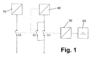
- This auxiliary circuit 40 can be connected to the supply network via a first switch S1 and a second switch S2 and, on the one hand, controls the second switch S2 and, on the other hand, also controls a third switch S3 which connects the control circuit 10 to the supply network or disconnects it.
- the electrical pulse of the actuating element 20 or the forming circuit 30 controls the function of the first switch S1. That the pulse generator of the actuating element 20, upon mechanical actuation of the actuating element 20, sends an electrical pulse to the forming circuit 30, which converts the pulse such that it causes a momentary closure of the first switch S1. Via the first switch S1 thus closed, the auxiliary circuit 40 is connected to the supply network and thus activated.
- the activated auxiliary circuit 40 then closes the second switch S2 and thus generates a latch. That the auxiliary circuit 40 remains connected via the closed second switch S2 to the supply network, even if the first switch S1 opens again after a short time.
- the activated auxiliary circuit 40 further includes the third switch S3 and thus also connects the control circuit 10 and thus the entire electronic device to the supply network.
- the actuator 20 can also be used to turn off the control device or the device.
- the first switch S1 is closed by a pulse generated by the pulse generator of the actuating element 20.
- This closing of the first switch S1 is detected by the auxiliary circuit 40, which then again the second switch S2 is actuated, that opens in this case, and thus the auxiliary circuit 40 is disconnected from the mains supply and so deactivated.
- the deactivation of the auxiliary circuit 40 simultaneously causes an opening of the third switch S3, so that the control circuit 10 and thus the device are disconnected from the supply network.
- an additional switching element which does not necessarily have to be designed as a passive component may be provided.
Landscapes
- Selective Calling Equipment (AREA)
- Electronic Switches (AREA)
Abstract
Description
- Die vorliegende Erfindung betrifft eine Steuervorrichtung für elektronische Geräte, insbesondere für elektronische Haushaltsgeräte.
- Bei elektronischen Geräten ohne Netzschalter wird die Steuerschaltung zum Ansteuern des Geräts oder zumindest ein Teil davon bei Nichtgebrauch des Geräts üblicherweise im Stand by - Zustand gehalten. Auf diese Weise wird sichergestellt, dass mittels Betätigung eines entsprechenden elektrischen Schaltelements diese Steuerschaltung wieder aktiviert wird und das Gerät in seinen Betriebszustand übergeht.
- Ein Vorteil dieses Konzepts ist es, dass die Steuerschaltung über ein leistungsschwaches und damit kostengünstiges elektrisches Schaltetement in Betrieb genommen werden kann. Nachteilig an dieser Lösung ist jedoch, dass die Steuervorrichtung ständig mit dem Versorgungsnetz verbunden ist und deshalb auch ständig elektrische Energie in Form des so genannten Ruhestroms aus dem Versorgungsnetz zieht.
- Der vorliegenden Erfindung liegt daher die Aufgabe zugrunde, eine verbesserte Steuervorrichtung ohne Netzschalter, aber mit vermindertem Energieverbrauch zu schaffen.
- Diese Aufgabe wird gelöst durch eine Steuervorrichtung mit den Merkmalen des Anspruchs 1. Vorteilhafte Ausgestaltungen und Weiterbildungen der Erfindung sind Gegenstand der abhängigen Ansprüche.
- Die erfindungsgemäße Steuervorrichtung weist eine Steuerschaltung, welche bei ausgeschalteter Steuervorrichtung von einem Versorgungsnetz getrennt ist, und ein Betätigungselement zum Einschalten der Steuervorrichtung, bei dessen Betätigung die Steuerschaltung mit dem Versorgungsnetz verbunden wird, auf. Das Betätigungselement wiederum weist einen passiven elektrischen Impulsgeber auf, der bei einer Betätigung des Betätigungselements einen elektrischen Impuls erzeugt, der eine Verbindung der Steuerschaltung mit dem Versorgungsnetz bewirkt. Das Betätigungselement fungiert als Hauptschalter.
- Durch die Verwendung eines Betätigungselements mit einem passiven elektrischen Impulsgeber kann die gesamte Steuervorrichtung im ausgeschalteten Zustand von dem Versorgungsnetz getrennt werden. Mit anderen Worten ist kein Stand by - Betrieb der Steuerschaltung notwendig, der auch bei ausgeschalteter Steuervorrichtung Energie verbrauchen würde.
- Unter einem "passiven elektrischen Impulsgeber" wird ein Element verstanden, das bei seiner Betätigung ohne Zufuhr elektrischer Energie einen elektrischen Impuls erzeugt. Der passive elektrische Impulsgeber muss also nicht mit dem Versorgungsnetz verbunden sein und verbraucht daher auch keinen Ruhestrom. Die Erzeugung des elektrischen Impulses wird durch ein mechanisch (z.B. durch Berührung, Druck, etc.) zu bedienendes Element ausgelöst, das zum Beispiel als berührungsempfindlicher Schalter oder als Drucktaste ausgeführt sein kann.
- Der passive elektrische Impulsgeber des Betätigungselements kann beispielsweise ein piezoelektrisches Element oder ein induktives Element enthalten, bzw. durch ein derartiges Element gebildet sein.
- In einer Ausgestaltung der Erfindung kann ferner eine Umformschaltung zum Umformen des von dem passiven elektrischen Impulsgeber erzeugten Impulses in eine geeignete Form vorgesehen sein, sodass der erzeugte und ggf. umgeformte elektrische Impuls die gewünschten Steuervorgänge auslöst.
- In einer bevorzugten Ausgestaltung der Erfindung kann zwischen dem Betätigungselement und der Steuerschaltung eine Hilfsschaltung angeordnet sein. Diese Hilfsschaltung ist bei ausgeschalteter Steuervorrichtung von dem Versorgungsnetz getrennt. Durch einen von dem Impulsgeber des Betätigungselements erzeugten und ggf. durch die Umformschaltung umgeformten Impuls wird die Hilfsschaltung dauerhaft mit dem Versorgungsnetz verbunden und verbindet in diesem mit dem Versorgungsnetz verbundenen Zustand auch die Steuerschaltung mit dem Versorgungsnetz. Die Hilfsschaltung verfügt über eine so genannte Selbsthaltefunktion, d.h. ein kurzzeitiger elektrischer Impuls von dem Impulsgeber genügt, um die Hilfsschaltung dauerhaft in einen anderen Betriebszustand, hier eine Verbindung mit dem Versorgungsnetz, zu versetzen.
- Zur Realisierung dieser Selbsthaltefunktion kann die Hilfsschaltung zum Beispiel über einen ersten Schalter und einen zweiten Schalter mit dem Versorgungsnetz verbindbar sein. Bei ausgeschalteter Steuervorrichtung sind beide Schalter offen, d.h. ist die Hilfsschaltung von dem Versorgungsnetz getrennt. Ein von dem passiven elektrischen Impulsgeber des Betätigungselements erzeugter Impuls schließt dann den ersten Schalter kurzzeitig, wobei die Hilfsschaltung bei geschlossenem erstem Schalter den zweiten Schalter betätigt, d.h. zum Einschalten der Steuervorrichtung schließt.
- Bei dieser Ausführungsform kann die Hilfsschaltung bei geschlossenem zweitem Schalter die Steuerschaltung über einen dritten Schalter mit dem Versorgungsnetz verbinden.
- In einer weiteren Ausgestaltung der Erfindung kann das Betätigungselement vorzugsweise auch dem Ausschalten der Steuervorrichtung dienen. Eine Betätigung des Betätigungselements zum Ausschalten erzeugt dann einen elektrischen Impuls, der eine Trennung der Hilfsschaltung und damit auch der Steuerschaltung von dem Versorgungsnetz bewirkt.
- Die oben beschriebene Steuervorrichtung der Erfindung ist in vorteilhafter Weise für elektronische Haushaltsgeräte wie zum Beispiel Herde, Kochfelder, Mikrowellenöfen, Waschmaschinen, Trockner, Spülmaschinen, TV-Geräte, Hifi-Geräte usw. einsetzbar, ohne dass die Erfindung auf diese Anwendung beschränkt sein soll.
- Obige sowie weitere Merkmale, Vorteile und Anwendungsmöglichkeiten der Erfindung werden aus der nachfolgenden Beschreibung eines bevorzugten, nichteinschränkenden Ausführungsbeispiels unter Bezug auf die beiliegende Zeichnung besser verständlich. Darin zeigt die einzige Figur ein stark vereinfachtes Blockschaltbild einer Steuervorrichtung gemäß der vorliegenden Erfindung.
- Die in
Figur 1 veranschaulichte Steuervorrichtung sieht vor, mit Hilfe eines kurzzeitigen elektrischen Impulses, der bei Betätigung eines passiven, d.h. nicht mit einem Versorgungsnetz verbundenen Bauelements erzeugt wird, die Steuervorrichtung und damit das gesamte Gerät zu aktivieren. - Die Steuervorrichtung enthält insbesondere eine Steuerschaltung 10 zum Ansteuern des jeweiligen elektronischen Geräts sowie ein Betätigungselement 20 zum Ein- und Ausschalten dieser Steuervorrichtung und damit des gesamten Geräts. Ist die Bedienblende mit Touch Sensoren ausgestattet, so ist vorzugsweise auch das Betätigungselement 20 als ein berührungsempfindlicher Schalter ausgeführt, um ein homogenes Blendendesign zu erzielen. Grundsätzlich kann das Betätigungselement 20 aber ebenso als Drucktaste oder dergleichen ausgebildet werden.
- Das Betätigungselement 20 weist einen passiven elektrischen Impulsgeber auf, der bei Betätigung des Betätigungselements 20 einen elektrischen Impuls erzeugt. Als passives Bauelement ist dieser Impulsgeber nicht mit dem Versorgungsnetz verbunden. Dieser passive elektrische Impulsgeber kann zum Beispiel ein piezoelektrisches Element oder ein induktives Element enthalten.
- Der von dem Impulsgeber des Betätigungselements 20 erzeugte Impuls wird vorzugsweise in einer Umformschaltung 30 in geeigneter Weise umgeformt. Zu den Umformungsmaßnahmen gehören insbesondere auch eine Veränderung der Form des elektrischen Impulses und eine Veränderung der Impulsdauer.
- Zwischen das Betätigungselement 20 und die Umformschaltung 30 einerseits und die Steuerschaltung 10 andererseits ist ferner eine Hilfsschaltung 40 mit einer Selbsthaltefunktion gesetzt. Diese Hilfsschaltung 40 ist über einen ersten Schalter S1 und einen zweiten Schalter S2 mit dem Versorgungsnetz verbindbar und steuert einerseits den zweiten Schalter S2 und andererseits auch einen dritten Schalter S3, der die Steuerschaltung 10 mit dem Versorgungsnetz verbindet bzw. von ihm trennt.
- Der elektrische Impuls des Betätigungselements 20 bzw. der Umformschaltung 30 steuert die Funktion des ersten Schalters S1. D.h. der Impulsgeber des Betätigungselements 20 sendet bei mechanischer Betätigung des Betätigungselements 20 einen elektrischen Impuls an die Umformschaltung 30, die den Impuls so umwandelt, dass dieser ein kurzzeitiges Schließen des ersten Schalters S1 bewirkt. Über den so geschlossenen ersten Schalter S1 wird die Hilfsschaltung 40 mit dem Versorgungsnetz verbunden und damit aktiviert.
- Die aktivierte Hilfsschaltung 40 schließt dann den zweiten Schalter S2 und erzeugt so eine Selbsthaltung. D.h. die Hilfsschaltung 40 bleibt über den geschlossenen zweiten Schalter S2 mit dem Versorgungsnetz verbunden, auch wenn der erste Schalter S1 nach kurzer Zeit wieder öffnet. Die aktivierte Hilfsschaltung 40 schließt weiter den dritten Schalter S3 und verbindet damit auch die Steuerschaltung 10 und damit das gesamte elektronische Gerät mit dem Versorgungsnetz.
- Das Betätigungselement 20 kann auch zum Ausschalten der Steuervorrichtung bzw. des Geräts benutzt werden. Ausgehend von dem eingeschalteten Betriebszustand wird der erste Schalter S1 durch einen von dem Impulsgeber des Betätigungselements 20 erzeugten Impuls geschlossen. Dieses Schließen des ersten Schalters S1 wird von der Hilfsschaltung 40 erfasst, die daraufhin wieder den zweiten Schalter S2 betätigt, also in diesem Fall öffnet, und damit die Hilfsschaltung 40 von dem Versorgungsnetz trennt und so deaktiviert. Die Deaktivierung der Hilfsschaltung 40 bewirkt gleichzeitig ein Öffnen des dritten Schalters S3, sodass die Steuerschaltung 10 und damit das Gerät von dem Versorgungsnetz getrennt werden. Alternativ kann zum Ausschalten der Steuervorrichtung auch ein zusätzliches Schaltelement, welches nicht notwendigerweise als passives Bauelement ausgebildet sein muss, vorgesehen sein.
- In diesem ausgeschalteten Zustand ist dann die gesamte Steuervorrichtung (einschließlich des Betätigungselements 20 und seines Impulsgebers) von dem Versorgungsnetz getrennt und verbraucht - im Gegensatz zu dem Stand by - Betriebszustand herkömmlicher Steuervorrichtungen - keine elektrische Energie.
-
- 10
- Steuerschaltung
- 20
- Betätigungselement
- 30
- Umformschaltung
- 40
- Hilfsschaltung
Claims (8)
- Steuervorrichtung, mit
einer Steuerschaltung (10), die bei ausgeschalteter Steuervorrichtung von einem Versorgungsnetz getrennt ist; und
einem Betätigungselement (20) zum Einschalten der Steuervorrichtung, bei dessen Betätigung die Steuerschaltung (10) mit dem Versorgungsnetz verbunden wird,
dadurch gekennzeichnet,
dass das Betätigungselement (20) einen passiven elektrischen Impulsgeber aufweist, der bei einer Betätigung des Betätigungselements (20) einen elektrischen Impuls erzeugt, der eine Verbindung der Steuerschaltung (10) mit dem Versorgungsnetz bewirkt. - Steuervorrichtung nach Anspruch 1,
dadurch gekennzeichnet,
dass der Impulsgeber des Betätigungselements (20) ein piezoelektrisches Element enthält. - Steuervorrichtung nach Anspruch 1,
dadurch gekennzeichnet,
dass der Impulsgeber des Betätigungselements (20) ein induktives Element enthält. - Steuervorrichtung nach einem der vorherigen Ansprüche,
dadurch gekennzeichnet,
dass eine Umformschaltung (30) zum Umformen des von dem Impulsgeber erzeugten Impulses in eine geeignete Form vorgesehen ist. - Steuervorrichtung nach einem der vorherigen Ansprüche,
dadurch gekennzeichnet,
dass zwischen dem Betätigungselement (20) und der Steuerschaltung (10) eine Hilfsschaltung (40) angeordnet ist, welche bei ausgeschalteter Steuervorrichtung von dem Versorgungsnetz getrennt ist, welche durch einen von dem Impulsgeber des Betätigungselements (20) erzeugten Impuls dauerhaft mit dem Versorgungsnetz verbunden wird und welche in einem mit dem Versorgungsnetz verbundenen Zustand die Steuerschaltung (10) mit dem Versorgungsnetz verbindet. - Steuervorrichtung nach Anspruch 5,
dadurch gekennzeichnet,
dass die Hilfsschaltung (40) über einen ersten Schalter (S1) und einen zweiten Schalter (S2) mit dem Versorgungsnetz verbindbar ist, wobei bei ausgeschalteter Steuervorrichtung der erste und der zweite Schalter (S1, S2) offen sind, wobei ein von dem Impulsgeber des Betätigungselements (20) erzeugter Impuls den ersten Schalter (S1) kurzzeitig schließt und wobei die Hilfsschaltung (40) bei geschlossenem ersten Schalter den zweiten Schalter (S2) betätigt. - Steuervorrichtung nach Anspruch 6,
dadurch gekennzeichnet,
dass die Hilfsschaltung (40) bei geschlossenem zweiten Schalter (S2) die Steuerschaltung (10) mit dem Versorgungsnetz verbindet, indem sie einen dritten Schalter (S3) schließt. - Steuervorrichtung nach einem der vorherigen Ansprüche,
dadurch gekennzeichnet,
dass das Betätigungselement (20) auch dem Ausschalten der Steuervorrichtung dient.
Priority Applications (1)
| Application Number | Priority Date | Filing Date | Title |
|---|---|---|---|
| PL10001353T PL2224595T3 (pl) | 2009-02-26 | 2010-02-10 | Urządzenie sterujące |
Applications Claiming Priority (1)
| Application Number | Priority Date | Filing Date | Title |
|---|---|---|---|
| DE102009010409A DE102009010409B4 (de) | 2009-02-26 | 2009-02-26 | Steuervorrichtung |
Publications (2)
| Publication Number | Publication Date |
|---|---|
| EP2224595A1 true EP2224595A1 (de) | 2010-09-01 |
| EP2224595B1 EP2224595B1 (de) | 2013-04-17 |
Family
ID=42202476
Family Applications (1)
| Application Number | Title | Priority Date | Filing Date |
|---|---|---|---|
| EP10001353.1A Not-in-force EP2224595B1 (de) | 2009-02-26 | 2010-02-10 | Steuervorrichtung |
Country Status (3)
| Country | Link |
|---|---|
| EP (1) | EP2224595B1 (de) |
| DE (1) | DE102009010409B4 (de) |
| PL (1) | PL2224595T3 (de) |
Families Citing this family (1)
| Publication number | Priority date | Publication date | Assignee | Title |
|---|---|---|---|---|
| DE102012012698A1 (de) | 2012-06-26 | 2014-01-02 | Diehl Ako Stiftung & Co. Kg | Bedienvorrichtung für ein elektronisches Gerät und Verfahren zum Betreiben eines elektronischen Gerätes |
Citations (3)
| Publication number | Priority date | Publication date | Assignee | Title |
|---|---|---|---|---|
| EP1460661A1 (de) | 2003-03-15 | 2004-09-22 | Schott Glas | Schaltanordnung für ein Elektrogerät |
| EP1868276A1 (de) | 2006-06-14 | 2007-12-19 | Electrolux Home Products Corporation N.V. | Schaltung für ein elektrisches Gerät |
| EP1978618A1 (de) | 2007-04-03 | 2008-10-08 | BSH Bosch und Siemens Hausgeräte GmbH | Elektrogerät mit verringertem Standbyverbrauch |
Family Cites Families (3)
| Publication number | Priority date | Publication date | Assignee | Title |
|---|---|---|---|---|
| DE2824646A1 (de) * | 1978-06-05 | 1979-12-06 | Licentia Gmbh | Schaltung zur schnellbremsung eines elektrischen antriebsmotors |
| DE10255449A1 (de) * | 2002-11-28 | 2004-06-24 | Daimlerchrysler Ag | Vorrichtung zum Wecken eines Steuergerätes |
| DE102007052089B4 (de) * | 2007-10-31 | 2022-11-03 | BSH Hausgeräte GmbH | Elektrogerät mit verringerter Standby-Leistung |
-
2009
- 2009-02-26 DE DE102009010409A patent/DE102009010409B4/de not_active Expired - Fee Related
-
2010
- 2010-02-10 PL PL10001353T patent/PL2224595T3/pl unknown
- 2010-02-10 EP EP10001353.1A patent/EP2224595B1/de not_active Not-in-force
Patent Citations (3)
| Publication number | Priority date | Publication date | Assignee | Title |
|---|---|---|---|---|
| EP1460661A1 (de) | 2003-03-15 | 2004-09-22 | Schott Glas | Schaltanordnung für ein Elektrogerät |
| EP1868276A1 (de) | 2006-06-14 | 2007-12-19 | Electrolux Home Products Corporation N.V. | Schaltung für ein elektrisches Gerät |
| EP1978618A1 (de) | 2007-04-03 | 2008-10-08 | BSH Bosch und Siemens Hausgeräte GmbH | Elektrogerät mit verringertem Standbyverbrauch |
Also Published As
| Publication number | Publication date |
|---|---|
| DE102009010409B4 (de) | 2013-02-21 |
| DE102009010409A1 (de) | 2010-09-02 |
| EP2224595B1 (de) | 2013-04-17 |
| PL2224595T3 (pl) | 2013-09-30 |
Similar Documents
| Publication | Publication Date | Title |
|---|---|---|
| DE102008044378A1 (de) | Haushaltsgerät mit automatischer Abschaltung | |
| DE10311447B4 (de) | Schaltungsanordnung für ein Elektrogerät | |
| DE102007016075A1 (de) | Elektrogerät mit verringertem Standbyverbrauch | |
| EP2220737B1 (de) | Schaltungsanordnung zum betreiben eines hausgeräts | |
| DE102008011279A1 (de) | Elektrisches Gerät | |
| EP2315337B1 (de) | Haushaltsgerät und Verfahren zum Betreiben eines Haushaltsgeräts | |
| DE102009045967B3 (de) | (Stand-by)-Schaltungsanordnung zum Betreiben eines Haushaltsgeräts und entsprechendes Verfahren | |
| EP2224595B1 (de) | Steuervorrichtung | |
| EP2491845A2 (de) | Elektronisches Haushaltsgerät | |
| EP2056323A1 (de) | Elektrogerät mit verringerter Standby-Leistung | |
| EP3726714B1 (de) | Netzfiltervorrichtung für ein haushaltsgerät, haushaltsgerät sowie verfahren | |
| EP2177137B1 (de) | Elektrische Getränkebereitungsmaschine mit einer Steuereinheit | |
| EP2488088A2 (de) | Haushaltsgerät, insbesondere haushalts-geschirrspülmaschine | |
| EP1511359A2 (de) | Schaltungsanordnung für ein Elektrogerät | |
| EP3084060B1 (de) | Haushaltsgerät mit galvanisch getrennten schaltungsteilen | |
| DE202008006878U1 (de) | Elektromotorischer Möbelantrieb | |
| EP3719985A1 (de) | Haushaltsgerät mit einer elektrischen funktionseinheit sowie verfahren zu deren betrieb | |
| EP2212988B1 (de) | Verfahren zur erkennung der betätigung eines bedienelements einer bedienfront eines wechselrichters und bedienfront für einen wechselrichter | |
| DE102010012311A1 (de) | Steuerschaltung für ein elektronisches Haushaltsgerät | |
| DE102010038485A1 (de) | Schaltung und Verfahren zum Betreiben eines Hausgeräts sowie Hausgerät | |
| EP3191911B1 (de) | Schalteinrichtung zum schalten einer energieversorgung für eine elektronische steuereinheit, haushaltgerät und verfahren hierfür | |
| DE102010039660A1 (de) | Schaltungsanordnung zum Betreiben eines Hausgerätes, Tastermodul für ein Hausgerät und Verfahren zum Betreiben eines Hausgerätes | |
| WO2009027280A1 (de) | Elektrisches hausgerät | |
| EP2434516A1 (de) | Schaltungsanordnung zum Betreiben eines Haushaltgerätes | |
| DE102012012698A1 (de) | Bedienvorrichtung für ein elektronisches Gerät und Verfahren zum Betreiben eines elektronischen Gerätes |
Legal Events
| Date | Code | Title | Description |
|---|---|---|---|
| PUAI | Public reference made under article 153(3) epc to a published international application that has entered the european phase |
Free format text: ORIGINAL CODE: 0009012 |
|
| AK | Designated contracting states |
Kind code of ref document: A1 Designated state(s): AT BE BG CH CY CZ DE DK EE ES FI FR GB GR HR HU IE IS IT LI LT LU LV MC MK MT NL NO PL PT RO SE SI SK SM TR |
|
| AX | Request for extension of the european patent |
Extension state: AL BA RS |
|
| 17P | Request for examination filed |
Effective date: 20100831 |
|
| 17Q | First examination report despatched |
Effective date: 20110907 |
|
| GRAP | Despatch of communication of intention to grant a patent |
Free format text: ORIGINAL CODE: EPIDOSNIGR1 |
|
| GRAS | Grant fee paid |
Free format text: ORIGINAL CODE: EPIDOSNIGR3 |
|
| GRAA | (expected) grant |
Free format text: ORIGINAL CODE: 0009210 |
|
| AK | Designated contracting states |
Kind code of ref document: B1 Designated state(s): AT BE BG CH CY CZ DK EE ES FI FR GB GR HR HU IE IS IT LI LT LU LV MC MK MT NL NO PL PT RO SE SI SK SM TR |
|
| RBV | Designated contracting states (corrected) |
Designated state(s): AT BE BG CH CY CZ DK EE ES FI FR GB GR HR HU IE IS IT LI LT LU LV MC MK MT NL NO PL PT RO SE SI SK SM TR |
|
| REG | Reference to a national code |
Ref country code: DE Ref legal event code: R108 Ref country code: GB Ref legal event code: FG4D Free format text: NOT ENGLISH |
|
| REG | Reference to a national code |
Ref country code: CH Ref legal event code: EP |
|
| REG | Reference to a national code |
Ref country code: IE Ref legal event code: FG4D Free format text: LANGUAGE OF EP DOCUMENT: GERMAN |
|
| REG | Reference to a national code |
Ref country code: AT Ref legal event code: REF Ref document number: 607836 Country of ref document: AT Kind code of ref document: T Effective date: 20130515 |
|
| REG | Reference to a national code |
Ref country code: DE Ref legal event code: R108 Effective date: 20130417 |
|
| REG | Reference to a national code |
Ref country code: LT Ref legal event code: MG4D |
|
| REG | Reference to a national code |
Ref country code: PL Ref legal event code: T3 |
|
| REG | Reference to a national code |
Ref country code: NL Ref legal event code: VDEP Effective date: 20130417 |
|
| PG25 | Lapsed in a contracting state [announced via postgrant information from national office to epo] |
Ref country code: SE Free format text: LAPSE BECAUSE OF FAILURE TO SUBMIT A TRANSLATION OF THE DESCRIPTION OR TO PAY THE FEE WITHIN THE PRESCRIBED TIME-LIMIT Effective date: 20130417 Ref country code: IS Free format text: LAPSE BECAUSE OF FAILURE TO SUBMIT A TRANSLATION OF THE DESCRIPTION OR TO PAY THE FEE WITHIN THE PRESCRIBED TIME-LIMIT Effective date: 20130817 Ref country code: FI Free format text: LAPSE BECAUSE OF FAILURE TO SUBMIT A TRANSLATION OF THE DESCRIPTION OR TO PAY THE FEE WITHIN THE PRESCRIBED TIME-LIMIT Effective date: 20130417 Ref country code: LT Free format text: LAPSE BECAUSE OF FAILURE TO SUBMIT A TRANSLATION OF THE DESCRIPTION OR TO PAY THE FEE WITHIN THE PRESCRIBED TIME-LIMIT Effective date: 20130417 Ref country code: PT Free format text: LAPSE BECAUSE OF FAILURE TO SUBMIT A TRANSLATION OF THE DESCRIPTION OR TO PAY THE FEE WITHIN THE PRESCRIBED TIME-LIMIT Effective date: 20130819 Ref country code: SI Free format text: LAPSE BECAUSE OF FAILURE TO SUBMIT A TRANSLATION OF THE DESCRIPTION OR TO PAY THE FEE WITHIN THE PRESCRIBED TIME-LIMIT Effective date: 20130417 Ref country code: GR Free format text: LAPSE BECAUSE OF FAILURE TO SUBMIT A TRANSLATION OF THE DESCRIPTION OR TO PAY THE FEE WITHIN THE PRESCRIBED TIME-LIMIT Effective date: 20130718 Ref country code: ES Free format text: LAPSE BECAUSE OF FAILURE TO SUBMIT A TRANSLATION OF THE DESCRIPTION OR TO PAY THE FEE WITHIN THE PRESCRIBED TIME-LIMIT Effective date: 20130728 Ref country code: NO Free format text: LAPSE BECAUSE OF FAILURE TO SUBMIT A TRANSLATION OF THE DESCRIPTION OR TO PAY THE FEE WITHIN THE PRESCRIBED TIME-LIMIT Effective date: 20130717 |
|
| PG25 | Lapsed in a contracting state [announced via postgrant information from national office to epo] |
Ref country code: HR Free format text: LAPSE BECAUSE OF FAILURE TO SUBMIT A TRANSLATION OF THE DESCRIPTION OR TO PAY THE FEE WITHIN THE PRESCRIBED TIME-LIMIT Effective date: 20130417 Ref country code: BG Free format text: LAPSE BECAUSE OF FAILURE TO SUBMIT A TRANSLATION OF THE DESCRIPTION OR TO PAY THE FEE WITHIN THE PRESCRIBED TIME-LIMIT Effective date: 20130717 Ref country code: LV Free format text: LAPSE BECAUSE OF FAILURE TO SUBMIT A TRANSLATION OF THE DESCRIPTION OR TO PAY THE FEE WITHIN THE PRESCRIBED TIME-LIMIT Effective date: 20130417 Ref country code: CY Free format text: LAPSE BECAUSE OF FAILURE TO SUBMIT A TRANSLATION OF THE DESCRIPTION OR TO PAY THE FEE WITHIN THE PRESCRIBED TIME-LIMIT Effective date: 20130417 |
|
| PG25 | Lapsed in a contracting state [announced via postgrant information from national office to epo] |
Ref country code: EE Free format text: LAPSE BECAUSE OF FAILURE TO SUBMIT A TRANSLATION OF THE DESCRIPTION OR TO PAY THE FEE WITHIN THE PRESCRIBED TIME-LIMIT Effective date: 20130417 Ref country code: CZ Free format text: LAPSE BECAUSE OF FAILURE TO SUBMIT A TRANSLATION OF THE DESCRIPTION OR TO PAY THE FEE WITHIN THE PRESCRIBED TIME-LIMIT Effective date: 20130417 Ref country code: DK Free format text: LAPSE BECAUSE OF FAILURE TO SUBMIT A TRANSLATION OF THE DESCRIPTION OR TO PAY THE FEE WITHIN THE PRESCRIBED TIME-LIMIT Effective date: 20130417 Ref country code: SK Free format text: LAPSE BECAUSE OF FAILURE TO SUBMIT A TRANSLATION OF THE DESCRIPTION OR TO PAY THE FEE WITHIN THE PRESCRIBED TIME-LIMIT Effective date: 20130417 |
|
| PLBE | No opposition filed within time limit |
Free format text: ORIGINAL CODE: 0009261 |
|
| STAA | Information on the status of an ep patent application or granted ep patent |
Free format text: STATUS: NO OPPOSITION FILED WITHIN TIME LIMIT |
|
| PG25 | Lapsed in a contracting state [announced via postgrant information from national office to epo] |
Ref country code: NL Free format text: LAPSE BECAUSE OF FAILURE TO SUBMIT A TRANSLATION OF THE DESCRIPTION OR TO PAY THE FEE WITHIN THE PRESCRIBED TIME-LIMIT Effective date: 20130417 Ref country code: RO Free format text: LAPSE BECAUSE OF FAILURE TO SUBMIT A TRANSLATION OF THE DESCRIPTION OR TO PAY THE FEE WITHIN THE PRESCRIBED TIME-LIMIT Effective date: 20130417 Ref country code: IT Free format text: LAPSE BECAUSE OF FAILURE TO SUBMIT A TRANSLATION OF THE DESCRIPTION OR TO PAY THE FEE WITHIN THE PRESCRIBED TIME-LIMIT Effective date: 20130417 |
|
| 26N | No opposition filed |
Effective date: 20140120 |
|
| BERE | Be: lapsed |
Owner name: DIEHL AKO STIFTUNG & CO. K.G. Effective date: 20140228 |
|
| PG25 | Lapsed in a contracting state [announced via postgrant information from national office to epo] |
Ref country code: MC Free format text: LAPSE BECAUSE OF FAILURE TO SUBMIT A TRANSLATION OF THE DESCRIPTION OR TO PAY THE FEE WITHIN THE PRESCRIBED TIME-LIMIT Effective date: 20130417 Ref country code: LU Free format text: LAPSE BECAUSE OF FAILURE TO SUBMIT A TRANSLATION OF THE DESCRIPTION OR TO PAY THE FEE WITHIN THE PRESCRIBED TIME-LIMIT Effective date: 20140210 |
|
| REG | Reference to a national code |
Ref country code: CH Ref legal event code: PL |
|
| GBPC | Gb: european patent ceased through non-payment of renewal fee |
Effective date: 20140210 |
|
| PG25 | Lapsed in a contracting state [announced via postgrant information from national office to epo] |
Ref country code: CH Free format text: LAPSE BECAUSE OF NON-PAYMENT OF DUE FEES Effective date: 20140228 Ref country code: LI Free format text: LAPSE BECAUSE OF NON-PAYMENT OF DUE FEES Effective date: 20140228 |
|
| REG | Reference to a national code |
Ref country code: IE Ref legal event code: MM4A |
|
| PG25 | Lapsed in a contracting state [announced via postgrant information from national office to epo] |
Ref country code: BE Free format text: LAPSE BECAUSE OF NON-PAYMENT OF DUE FEES Effective date: 20140228 Ref country code: IE Free format text: LAPSE BECAUSE OF NON-PAYMENT OF DUE FEES Effective date: 20140210 Ref country code: GB Free format text: LAPSE BECAUSE OF NON-PAYMENT OF DUE FEES Effective date: 20140210 |
|
| REG | Reference to a national code |
Ref country code: FR Ref legal event code: PLFP Year of fee payment: 6 |
|
| PGFP | Annual fee paid to national office [announced via postgrant information from national office to epo] |
Ref country code: FR Payment date: 20150219 Year of fee payment: 6 Ref country code: PL Payment date: 20150204 Year of fee payment: 6 |
|
| PG25 | Lapsed in a contracting state [announced via postgrant information from national office to epo] |
Ref country code: MT Free format text: LAPSE BECAUSE OF FAILURE TO SUBMIT A TRANSLATION OF THE DESCRIPTION OR TO PAY THE FEE WITHIN THE PRESCRIBED TIME-LIMIT Effective date: 20130417 |
|
| REG | Reference to a national code |
Ref country code: AT Ref legal event code: MM01 Ref document number: 607836 Country of ref document: AT Kind code of ref document: T Effective date: 20150210 |
|
| PG25 | Lapsed in a contracting state [announced via postgrant information from national office to epo] |
Ref country code: SM Free format text: LAPSE BECAUSE OF FAILURE TO SUBMIT A TRANSLATION OF THE DESCRIPTION OR TO PAY THE FEE WITHIN THE PRESCRIBED TIME-LIMIT Effective date: 20130417 |
|
| PG25 | Lapsed in a contracting state [announced via postgrant information from national office to epo] |
Ref country code: AT Free format text: LAPSE BECAUSE OF NON-PAYMENT OF DUE FEES Effective date: 20150210 |
|
| PG25 | Lapsed in a contracting state [announced via postgrant information from national office to epo] |
Ref country code: HU Free format text: LAPSE BECAUSE OF FAILURE TO SUBMIT A TRANSLATION OF THE DESCRIPTION OR TO PAY THE FEE WITHIN THE PRESCRIBED TIME-LIMIT; INVALID AB INITIO Effective date: 20100210 Ref country code: TR Free format text: LAPSE BECAUSE OF FAILURE TO SUBMIT A TRANSLATION OF THE DESCRIPTION OR TO PAY THE FEE WITHIN THE PRESCRIBED TIME-LIMIT Effective date: 20130417 |
|
| REG | Reference to a national code |
Ref country code: FR Ref legal event code: ST Effective date: 20161028 |
|
| PG25 | Lapsed in a contracting state [announced via postgrant information from national office to epo] |
Ref country code: FR Free format text: LAPSE BECAUSE OF NON-PAYMENT OF DUE FEES Effective date: 20160229 |
|
| PG25 | Lapsed in a contracting state [announced via postgrant information from national office to epo] |
Ref country code: PL Free format text: LAPSE BECAUSE OF NON-PAYMENT OF DUE FEES Effective date: 20160210 |
|
| PG25 | Lapsed in a contracting state [announced via postgrant information from national office to epo] |
Ref country code: MK Free format text: LAPSE BECAUSE OF FAILURE TO SUBMIT A TRANSLATION OF THE DESCRIPTION OR TO PAY THE FEE WITHIN THE PRESCRIBED TIME-LIMIT Effective date: 20130417 |