EP2224194A2 - Kühl- und/oder Gefriergerät - Google Patents
Kühl- und/oder Gefriergerät Download PDFInfo
- Publication number
- EP2224194A2 EP2224194A2 EP10001776A EP10001776A EP2224194A2 EP 2224194 A2 EP2224194 A2 EP 2224194A2 EP 10001776 A EP10001776 A EP 10001776A EP 10001776 A EP10001776 A EP 10001776A EP 2224194 A2 EP2224194 A2 EP 2224194A2
- Authority
- EP
- European Patent Office
- Prior art keywords
- air
- cooling
- areas
- refrigerator
- freezer
- Prior art date
- Legal status (The legal status is an assumption and is not a legal conclusion. Google has not performed a legal analysis and makes no representation as to the accuracy of the status listed.)
- Granted
Links
- 238000005057 refrigeration Methods 0.000 title 1
- 238000001816 cooling Methods 0.000 claims abstract description 43
- 238000007710 freezing Methods 0.000 claims abstract 12
- 230000008014 freezing Effects 0.000 claims abstract 12
- 238000005192 partition Methods 0.000 claims description 5
- 238000000605 extraction Methods 0.000 claims description 3
- 230000000694 effects Effects 0.000 description 2
- 206010037660 Pyrexia Diseases 0.000 description 1
- 239000012141 concentrate Substances 0.000 description 1
- 230000001276 controlling effect Effects 0.000 description 1
- 238000007599 discharging Methods 0.000 description 1
- 238000009413 insulation Methods 0.000 description 1
- 230000001105 regulatory effect Effects 0.000 description 1
- 235000013311 vegetables Nutrition 0.000 description 1
Images


Classifications
-
- F—MECHANICAL ENGINEERING; LIGHTING; HEATING; WEAPONS; BLASTING
- F25—REFRIGERATION OR COOLING; COMBINED HEATING AND REFRIGERATION SYSTEMS; HEAT PUMP SYSTEMS; MANUFACTURE OR STORAGE OF ICE; LIQUEFACTION SOLIDIFICATION OF GASES
- F25D—REFRIGERATORS; COLD ROOMS; ICE-BOXES; COOLING OR FREEZING APPARATUS NOT OTHERWISE PROVIDED FOR
- F25D17/00—Arrangements for circulating cooling fluids; Arrangements for circulating gas, e.g. air, within refrigerated spaces
- F25D17/04—Arrangements for circulating cooling fluids; Arrangements for circulating gas, e.g. air, within refrigerated spaces for circulating air, e.g. by convection
- F25D17/06—Arrangements for circulating cooling fluids; Arrangements for circulating gas, e.g. air, within refrigerated spaces for circulating air, e.g. by convection by forced circulation
- F25D17/062—Arrangements for circulating cooling fluids; Arrangements for circulating gas, e.g. air, within refrigerated spaces for circulating air, e.g. by convection by forced circulation in household refrigerators
- F25D17/065—Arrangements for circulating cooling fluids; Arrangements for circulating gas, e.g. air, within refrigerated spaces for circulating air, e.g. by convection by forced circulation in household refrigerators with compartments at different temperatures
-
- F—MECHANICAL ENGINEERING; LIGHTING; HEATING; WEAPONS; BLASTING
- F25—REFRIGERATION OR COOLING; COMBINED HEATING AND REFRIGERATION SYSTEMS; HEAT PUMP SYSTEMS; MANUFACTURE OR STORAGE OF ICE; LIQUEFACTION SOLIDIFICATION OF GASES
- F25B—REFRIGERATION MACHINES, PLANTS OR SYSTEMS; COMBINED HEATING AND REFRIGERATION SYSTEMS; HEAT PUMP SYSTEMS
- F25B2600/00—Control issues
- F25B2600/11—Fan speed control
- F25B2600/112—Fan speed control of evaporator fans
-
- F—MECHANICAL ENGINEERING; LIGHTING; HEATING; WEAPONS; BLASTING
- F25—REFRIGERATION OR COOLING; COMBINED HEATING AND REFRIGERATION SYSTEMS; HEAT PUMP SYSTEMS; MANUFACTURE OR STORAGE OF ICE; LIQUEFACTION SOLIDIFICATION OF GASES
- F25D—REFRIGERATORS; COLD ROOMS; ICE-BOXES; COOLING OR FREEZING APPARATUS NOT OTHERWISE PROVIDED FOR
- F25D2317/00—Details or arrangements for circulating cooling fluids; Details or arrangements for circulating gas, e.g. air, within refrigerated spaces, not provided for in other groups of this subclass
- F25D2317/06—Details or arrangements for circulating cooling fluids; Details or arrangements for circulating gas, e.g. air, within refrigerated spaces, not provided for in other groups of this subclass with forced air circulation
- F25D2317/065—Details or arrangements for circulating cooling fluids; Details or arrangements for circulating gas, e.g. air, within refrigerated spaces, not provided for in other groups of this subclass with forced air circulation characterised by the air return
- F25D2317/0652—Details or arrangements for circulating cooling fluids; Details or arrangements for circulating gas, e.g. air, within refrigerated spaces, not provided for in other groups of this subclass with forced air circulation characterised by the air return through the corner
-
- F—MECHANICAL ENGINEERING; LIGHTING; HEATING; WEAPONS; BLASTING
- F25—REFRIGERATION OR COOLING; COMBINED HEATING AND REFRIGERATION SYSTEMS; HEAT PUMP SYSTEMS; MANUFACTURE OR STORAGE OF ICE; LIQUEFACTION SOLIDIFICATION OF GASES
- F25D—REFRIGERATORS; COLD ROOMS; ICE-BOXES; COOLING OR FREEZING APPARATUS NOT OTHERWISE PROVIDED FOR
- F25D2317/00—Details or arrangements for circulating cooling fluids; Details or arrangements for circulating gas, e.g. air, within refrigerated spaces, not provided for in other groups of this subclass
- F25D2317/06—Details or arrangements for circulating cooling fluids; Details or arrangements for circulating gas, e.g. air, within refrigerated spaces, not provided for in other groups of this subclass with forced air circulation
- F25D2317/068—Details or arrangements for circulating cooling fluids; Details or arrangements for circulating gas, e.g. air, within refrigerated spaces, not provided for in other groups of this subclass with forced air circulation characterised by the fans
- F25D2317/0682—Two or more fans
Definitions
- the present invention relates to a refrigerator and / or freezer with at least a first and a second region in the interior of the refrigerator and / or freezer.
- Known refrigerators have for the cooling of areas located in the interior separated areas a fan and a plurality of air ducts and flaps to adjust the temperature in the respective areas. This makes it possible to obtain a plurality of temperature zones in the interior of a refrigerator, so that better account can be taken of the different cooling requirements of the refrigerated goods to be stored in the appliance.
- the fan is usually located in the rear, upper region of a cooling air duct and blows the air coming from the interior of the refrigerator via an evaporator, so that this air is cooled again. The thus cooled air is then passed through openings in the respective areas or compartments or temperature zones.
- this type of regulation of the temperature of the individual cooling zones in a cooling device can not prevent slight temperature fluctuations occurring in the individual temperature zones. Therefore, in particular, a more targeted and faster adjustment, e.g. desirable to a constant value of the temperature.
- a refrigerator and / or freezer with the features of claim 1.
- a refrigerator and / or freezer has at least a first and a second region in the interior of the refrigerator and / or freezer.
- a plurality of air circulation means are provided, wherein in each case at least one air circulation means is assigned to one area.
- the interior is preferably the interior of the cooling part of the refrigerator and / or freezer.
- the device additionally has a freezer compartment with an interior separated from the interior of the refrigerator compartment.
- the region is an independent temperature zone and / or that the regions have mutually different temperatures.
- the first region may have a temperature of approximately 4 ° C. and a second region may have a temperature of approximately 8 ° C.
- the ranges have temperatures between -3 ° C to + 8 ° C.
- the respective temperatures in the individual areas can be identical or be partially identical, but also be chosen completely different.
- the areas are arranged one above the other and / or one below the other and / or next to each other.
- a large first area is provided which has a larger volume than the at least one further second area.
- one region is the main region of the cooling part for the storage of goods to be cooled, and the second region is an extraction compartment for the cooling, e.g. of vegetables is.
- a second area is a 0 ° C zone or a BioFresh area.
- a second area is designed as a drawer or pull-out compartment. It is particularly advantageous if the pull-out compartment is designed to be transparent. In principle, it is conceivable that all second areas are designed as BioFresh subjects.
- Air guiding means may be, for example, channels, shafts, flaps and / or other deflection means for air, which either lead to the respective area or be discharged from the respective area.
- the areas have common, continuous walls, the areas being separated from one another by intermediate floors.
- air from the air guidance means to be able to be inflated by the air circulation means in the region assigned to the air circulation means.
- the air circulation means is a fan.
- the actuation of the fans takes place via a control and / or regulating unit.
- This may be the device control of the refrigerator and / or freezer.
- the speed of a fan the temperature can thus be adjusted in an area or compartment.
- the air guide means comprises a cooling air duct, a cooling air duct and / or an air exhaust duct or is designed as such.
- At least one evaporator preferably a central evaporator is arranged in the cooling air shaft.
- a central evaporator can extend almost over the entire height of the interior and serve for the cooling of the air for all areas. It is particularly advantageous if several areas are arranged one above the other and the central evaporator extends over all areas. This results in the advantage that the air passed by the central evaporator and thereby cooled air can be injected directly into the respective area or the respective compartment by means of the respective air circulation means without great detours.
- the areas are connected to an air extraction duct. This makes it possible, for example, first to concentrate the warm air from the respective regions or temperature zones and then to cool it down, ie to supply, for example, to a central evaporator or to pass it and thereby cool it.
- the areas are each connected via an air outlet opening with a common air exhaust duct.
- This embodiment is space-saving and allows, for example, an exploitation of the chimney effect and in particular when the air outlet duct is arranged vertically.
- cooling air duct and an air outlet duct are provided, wherein both are arranged behind the rear wall of the areas.
- the cooling air duct and the air exhaust duct are accommodated together in the duct which is formed by the rear wall of the regions and by the rear inside of the inner container of the refrigerator and / or freezer.
- cooling air duct and air outlet duct are separated by a common partition, wherein in the upper part of the partition over an opening air passes from the air outlet duct into the cooling air duct.
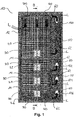
- Fig. 1 shows a schematic representation of the front of a refrigerator and / or freezer 10 with four arranged in the interior 12 of the refrigerator and / or freezer 10, superposed areas 20, 22, 24, 26, each having its own temperature zone 20, 22, 24, 26 represent.
- the top of the interior 12 arranged region 20 a much larger internal volume than the other areas 22, 24, 26th
- the three lower regions 22, 24, 26 are 0 ° C zones or BioFresh zones.
- the areas 22, 24, 26 can be designed as compartments or as pull-out compartments. In an embodiment with pull-out compartments, for example, it is conceivable that transparent drawers can be inserted and ejected into the areas 22, 24, 26.
- the regions 20, 22, 24, 26 can in principle each have a different but also identical temperature. It can thus be provided that the temperature in the first region 20 is approximately 4 ° C., while the temperature in the regions 22, 24, 26 is approximately 0 ° C. in each case. In principle, it can also be provided that the temperature in the regions 22, 24, 26 is higher or even lower than 0 ° C.
- the areas 20, 22, 24, 26 are separated from each other to form an independent temperature zone by continuous shelves 14.
- additional insulation layers may be incorporated, which are not shown in detail in the figures.
- Each area 20, 22, 24, 26 is in each case assigned an air circulation means 30 designed as a fan 30 and an air discharge opening 120, 122, 124, 126. As a result, a very precise temperature regulation in the respective cooling region 20, 22, 24, 26 is achieved.
- the fans 30 blow from the cooling air duct 30, which is behind the common rear wall 16 (see. Fig. 2 and 3 ) of the regions 20, 22, 24, 26, cooled air L in the respective regions 20, 22, 24, 26 a.
- the air L then flows through the respective region 20, 22, 24, 26 and leaves it through the air outlet opening 120, 122, 124, 126 assigned to the region 20, 22, 24, 26 into the chimney-like air channel 50 for the removal of the heated air L.
- the cooling air shaft 30 and the chimney-like air channel 50 are both located behind the rear wall 16 of the regions 20, 22, 24, 26 and are separated by the partition wall 62 of each other and connected by the head side opening 60 together. Both the cooling air duct 30 and the chimney-like air duct 50 are designed to be continuous over their entire height and are not divided by the shelves 14.
- the shelves 14 terminate at the common rear wall 16 of the areas 20, 22, 24, 26th
- the fan 30, which is assigned to the uppermost region 20, is located centrally in the lower part of the rear wall 16 of the region 20 and is fastened in the wall 16.
- the air outlet opening 120 assigned to the area 20 is located in the upper part of the rear wall 16 of the area 20.
- the fans 30 of the lower areas 22, 24, 26 are likewise oriented on the bottom side, while the respective air outlet opening is oriented on the head side.
- Fig. 2 shows the section BB through the in Fig. 1 shown refrigerator and / or freezer. From this sectional drawing the guidance of the L is again clarified.
- the air L from the cooling air shaft 40 with the central evaporator 70 is in each case blown on the bottom side into the areas or compartments 20, 22, 24, 26 or temperature zones 20, 22, 24, 26.
- the air L heated in the region 20 or the compartments 22, 24, 26 rises upwards and leaves the region 20 or the compartments 22, 24, 26 via the respectively assigned air outlet openings 120, 122, 124, 126 into the air channel 50th
- Fig. 3 shows the section AA looking from top to bottom through the in Fig. 1 and 2 shown refrigerator and / or freezer.
- the arrangement of the cooling air shaft 40 with the central evaporator 70 arranged therein and the chimney-like air duct 50 for discharging the heated air L behind the rear wall 16 is shown.
- the temperature in each compartment is predetermined and adjusted individually via a device control and regulation, not shown in detail. It is not absolutely necessary that the fans are controlled and operated synchronously.
- Flaps not shown in detail may further be provided to decouple the region 20 or one or more of the compartments 22, 24, 26 temporarily, for example, from the circulation circuit of the air L.
- Such flaps are associated with the fan 30 and the air outlet openings 120, 122, 124, 126 in such an embodiment of a refrigerator and / or freezer 10 and can also be preferably controlled by the device control and regulation.
Landscapes
- Engineering & Computer Science (AREA)
- Chemical & Material Sciences (AREA)
- Combustion & Propulsion (AREA)
- Physics & Mathematics (AREA)
- Mechanical Engineering (AREA)
- Thermal Sciences (AREA)
- General Engineering & Computer Science (AREA)
- Cold Air Circulating Systems And Constructional Details In Refrigerators (AREA)
Abstract
Description
- Die vorliegende Erfindung betrifft ein Kühl- und/oder Gefriergerät mit wenigstens einem ersten und einem zweiten Bereich im Innenraum des Kühl- und/oder Gefriergeräts.
- Bekannte Kühlgeräte weisen für die Kühlung von im Innenraum befindlichen voneinander abgetrennten Bereichen einen Ventilator und mehrere Luftführungskanäle sowie Klappen auf, um die Temperatur in den jeweiligen Bereichen einzustellen. Dadurch wird es möglich, im Innenraum eines Kühlgerätes mehrere Temperaturzonen zu erhalten, so dass den unterschiedlichen Kühlbedürfnissen des in das Gerät einzulagernden Kühlguts besser Rechnung getragen werden kann. Der Ventilator befindet sich dabei zumeist im hinteren, oberen Bereich eines Kühlluftkanals und bläst die aus dem Innenraum des Kühlgeräts kommende Luft über einen Verdampfer, so dass diese Luft wieder abkühlt wird. Die derart abgekühlte Luft wird sodann über Öffnungen in die jeweiligen Bereiche bzw. Fächer oder Temperaturzonen geleitet.
- Diese Art der Regelung der Temperatur der einzelnen Kühlzonen in einem Kühlgerät kann jedoch nicht verhindern, dass es zu leichten Temperaturschwankungen in den einzelnen Temperaturzonen kommt. Daher wäre insbesondere eine zielgerichtete und schnellere Einstellung bzw. Einregelung z.B. auf einen konstanten Wert der Temperatur wünschenswert.
- Es ist daher die Aufgabe der vorliegenden Erfindung, ein Kühl- und/oder Gefriergerät der eingangs genannten Art in vorteilhafter Weise weiterzubilden, insbesondere dahingehend, dass eine sehr genaue und zielgerichtete Temperaturregelung pro Kühlbereich ermöglicht wird.
- Diese Aufgabe wird erfindungsgemäß gelöst durch ein Kühl- und/oder Gefriergerät mit den Merkmalen des Anspruchs 1. Danach ist vorgesehen, dass ein Kühl- und/oder Gefriergerät wenigstens einen ersten und einem zweiten Bereich im Innenraum des Kühl- und/oder Gefriergeräts aufweist. Weiter sind mehrere Luftumwälzmittel vorgesehen, wobei jeweils wenigstens ein Luftumwälzmittel einem Bereich zugeordnet ist. Dadurch ergibt sich der Vorteil, dass beispielsweise die Zuführung von gekühlter Luft zu einem Bereich und damit auch die Temperatur in diesem Bereich genau eingestellt werden. Insbesondere wird dies durch dynamische Luftumwälzmittel ermöglicht, die es beispielsweise erlauben, den dem Bereich zuzuführenden Kühlluftstrom zu variieren. Bei dem Innenraum handelt es sich vorzugsweise um den Innenraum des Kühlteils des Kühl- und/oder Gefriergerätes. Grundsätzlich ist denkbar, dass das Gerät noch zusätzlich ein Gefrierteil mit einem vom Innenraum des Kühlteils abgesonderten Innenraum aufweist.
- Es ist weiter denkbar, dass der Bereich eine eigenständige Temperaturzone ist und/oder dass die Bereiche voneinander unterschiedliche Temperaturen aufweisen. So kann beispielsweise der erste Bereich eine Temperatur von ca. 4°C aufweisen und ein zweiter Bereich eine Temperatur von ca. 8°C aufweisen. Denkbar ist vorteilhafter Weise, dass die Bereiche Temperaturen zwischen -3°C bis +8°C aufweisen. Die jeweiligen Temperaturen in den einzelnen Bereichen können identisch oder teilweise identisch sein, aber auch vollkommen unterschiedlich gewählt werden.
- Darüber hinaus ist es möglich, dass die Bereiche übereinander und/oder untereinander und/oder nebeneinander angeordnet sind.
- Des weiteren kann vorgesehen sein, dass ein großer erster Bereich vorgesehen ist, der ein größeres Volumen als der wenigstens eine weitere zweite Bereich aufweist. Insbesondere ist dabei denkbar, dass ein Bereich der Hauptbereich des Kühlteils für die Einlagerung von Kühlgut ist und der zweite Bereich ein Auszugfach für die Kühlung z.B. von Gemüse ist.
- Es ist möglich, dass der und/oder die weiteren zweiten Bereiche unterhalb des großen ersten Bereichs angeordnet sind.
- Ferner ist denkbar, dass wenigstens ein zweiter Bereich eine 0°C-Zone bzw. ein BioFresh-Bereich ist. Vorzugsweise ist ein derartiger zweiter Bereich als Schubfach oder Auszugfach ausgeführt. Besonders vorteilhaft ist es, wenn das Auszugfach transparent ausgeführt ist. Grundsätzlich ist denkbar, dass sämtliche zweiten Bereiche als BioFresh-Fächer ausgeführt sind.
- Darüber hinaus kann vorgesehen sein, dass hinter einer Wandung der Bereiche wenigstens ein Luftführungsmittel vorgesehen ist und dass die Luftumwälzmittel in und/oder an der Wandung des Innenraums angeordnet und mit dem Luftführungsmittel für die Luftumwälzung in Verbindung stehen. Luftführungsmittel können beispielsweise Kanäle, Schächte, Klappen und/oder andere Umlenkmittel für Luft sein, die entweder zu dem jeweiligen Bereich hinzuführen oder aus dem jeweiligen Bereich abzuführen ist. Grundsätzlich ist denkbar, dass die Bereiche gemeinsame, durchgängige Wandungen haben, wobei die Bereiche durch Zwischenböden voneinander abgetrennt werden.
- Weiter ist möglich, dass Luft aus dem Luftführungsmittel durch die Luftumwälzmittel in den dem Luftumwälzmittel zugeordneten Bereich einblasbar ist.
- Des weiteren kann vorteilhafter Weise vorgesehen sein, dass das Luftumwälzmittel ein Ventilator ist. In diesem Zusammenhang ist denkbar, dass die Ansteuerung der Ventilatoren über eine Steuerungs- und/oder Regelungseinheit erfolgt. Dabei kann es sich um die Gerätesteuerung des Kühl- und/oder Gefriergeräts handeln. Beispielsweise über die Ansteuerung der Drehzahl eines Ventilators kann somit die Temperatur in einem Bereich bzw. Fach eingeregelt werden.
- Ferner ist es möglich, dass das Luftführungsmittel einen Kühlluftkanal, einen Kühlluftschacht und/oder einen Luftabzugskanal umfasst oder als solcher ausgeführt ist.
- Außerdem ist denkbar, dass im Kühlluftschacht wenigstens ein Verdampfer, vorzugsweise ein Zentralverdampfer angeordnet ist. Ein derartiger Zentralverdampfer kann sich dabei nahezu über die gesamte Höhe des Innenraums erstrecken und für die Abkühlung der Luft für sämtliche Bereiche dienen. Besonders vorteilhaft ist es, wenn mehrere Bereiche übereinander angeordnet sind und der Zentralverdampfer sich über alle Bereiche erstreckt. Dadurch ergibt sich der Vorteil, dass die am Zentralverdampfer vorbeigeführte und hierdurch abgekühlte Luft ohne große Umwege direkt mittels des jeweiligen Luftumwälzmittels in den jeweiligen Bereich bzw. das jeweilige Fach eingeblasen werden kann.
- Von Vorteil ist es, wenn die Bereiche mit einem Luftabzugskanal verbunden sind. Hierdurch wird es beispielsweise möglich, zunächst die warme Luft aus den jeweiligen Bereichen bzw. Temperaturzonen zu bündeln und sodann gesammelt abzukühlen, also beispielsweise einem Zentralverdampfer zuführen bzw. daran vorbeizuführen und hierdurch abzukühlen.
- Weiterhin kann vorgesehen sein, dass die Bereiche jeweils über eine Luftaustrittöffnung mit einem gemeinsamen Luftabzugskanal verbunden sind. Diese Ausgestaltung ist platzsparend und erlaubt z.B. eine Ausnutzung des Kamineffektes und zwar insbesondere dann, wenn der Luftabzugskanal senkrecht angeordnet ist.
- Es ist ferner denkbar, dass wenigstens ein Kühlluftschacht und ein Luftabzugskanal vorgesehen sind, wobei beide hinter der rückseitigen Wandung der Bereiche angeordnet sind. Beispielsweise ist in diesem Zusammenhang vorstellbar, dass Kühlluftschacht und Luftabzugskanal gemeinsam in dem Schacht, der durch die rückseitige Wandung der Bereiche und durch die rückseitige Innenseite des Innenbehälters der Kühl- und/oder Gefriergeräts ausgebildet ist, untergebracht sind.
- Von Vorteil ist es, wenn Kühlluftschacht und Luftabzugskanal durch eine gemeinsame Trennwand getrennt werden, wobei im oberen Teil der Trennwand über eine Öffnung Luft vom Luftabzugskanal in den Kühlluftschacht übertritt.
- Weitere Einzelheiten und Vorteile der Erfindung sollen nun anhand eines in der Zeichnung dargestellten Ausführungsbeispiels näher erläutert werden.
- Es zeigen:
- Fig. 1:
- eine schematische Darstellung der Anordnung der Komponenten eines Kühl- und/oder Gefriergerätes,
- Fig. 2:
- eine Darstellung des Schnittes B-B des in
Fig. 1 dargestellten Kühl- und/oder Gefriergerätes und - Fig. 3:
- eine Darstellung des Schnittes A-A des in
Fig. 1 und2 dargestellten Kühl- und/oder Gefriergerätes. -
Fig. 1 zeigt in schematischer Darstellung von vorne ein Kühl- und/oder Gefriergerät 10 mit vier im Innenraum 12 des Kühl- und/oder Gefriergerätes 10 angeordneten, übereinanderliegenden Bereichen 20, 22, 24, 26, die jeweils eine eigenständige Temperaturzone 20, 22, 24, 26 darstellen. Dabei weist der oben im Innenraum 12 angeordnete Bereich 20 ein wesentlich größeres Innenraumvolumen auf als die übrigen Bereiche 22, 24, 26. - Vorzugsweise ist vorgesehen, dass die drei unteren Bereiche 22, 24, 26 0°C-Zonen bzw. BioFresh Zonen sind. Dabei können die Bereiche 22, 24, 26 als Fächer bzw. als Auszugfächer ausgeführt sein. Bei einer Ausführungsform mit Auszugfächern ist beispielsweise denkbar, dass transparente Schubfächer in die Bereiche 22, 24, 26 ein- und ausgeschoben werden können.
- Die Bereiche 20, 22, 24, 26 können grundsätzlich jeweils eine von einander unterschiedliche, aber auch identische Temperatur aufweisen. So kann vorgesehen sein, dass die Temperatur im ersten Bereich 20 ca. 4°C ist, während die Temperatur in den Bereichen 22, 24, 26 jeweils ca. 0°C ist. Grundsätzlich kann ebenfalls vorgesehen sein, dass die Temperatur in den Bereichen 22, 24, 26 höher oder auch niedriger als 0°C ist.
- Die Bereiche 20, 22, 24, 26 sind zur Ausbildung einer eigenständigen Temperaturzone durch durchgehende Zwischenböden 14 voneinander abgetrennt. In diesen Zwischenböden können zusätzliche Isolationsschichten eingearbeitet sein, die jedoch in den Figuren nicht näher dargestellt sind.
- Jedem Bereich 20, 22, 24, 26 ist jeweils ein als Ventilator 30 ausgeführtes Luftumwälzmittel 30 sowie eine Luftabzugsöffnung 120, 122, 124, 126 zugeordnet. Hierdurch wird eine sehr genaue Temperaturregulierung im jeweiligen Kühlbereich 20, 22, 24, 26 erreicht.
- Die Ventilatoren 30 blasen aus dem Kühlluftschacht 30, der sich hinter der gemeinsamen rückseitigen Wandung 16 (vgl.
Fig. 2 und3 ) der Bereiche 20, 22, 24, 26 befindet, abgekühlte Luft L in die jeweiligen Bereiche 20, 22, 24, 26 ein. Die Luft L strömt sodann durch den jeweiligen Bereich 20, 22, 24, 26 und verläßt diesen durch die dem Bereich 20, 22, 24, 26 zugeordnete Luftaustrittöffnung 120, 122, 124, 126 in den kaminartigen Luftkanal 50 zur Abführung der erwärmten Luft L. - Der Kühlluftschacht 30 sowie der kaminartige Luftkanal 50 befinden beide sich hinter rückseitigen Wandung 16 der Bereiche 20, 22, 24, 26 und werden durch die Trennwand 62 von einander getrennt und durch die kopfseitig angeordnete Öffnung 60 miteinander verbunden. Sowohl der Kühlluftschacht 30 als auch der kaminartige Luftkanal 50 sind über ihre gesamte Höhe durchgängig ausgeführt und werden nicht durch die Zwischenböden 14 unterteilt. Die Zwischenböden 14 enden an der gemeinsamen rückseitigen Wandung 16 der Bereiche 20, 22, 24, 26.
- Die aus den Bereichen 20, 22, 24, 26 abgeführte, erwärmte Luft steigt im Luftkanal 50 nach oben und tritt über die Öffnung 60 in den Kühlluftschacht 30 ein. Dort strömt die Luft L am Zentralverdampfer 70 entlang und kühlt hierdurch ab. Danach wird die Luft erneut durch die Ventilatoren 30 in die jeweiligen Bereiche 20, 22, 24, 26 eingeblasen.
- Der Ventilator 30, der dem obersten Bereich 20 zugeordnet ist, befindet sich mittig im unteren Teil der rückseitigen Wandung 16 des Bereichs 20 und ist in der Wandung 16 befestigt. Die dem Bereich 20 zugeordnete Luftaustrittsöffnung 120 befindet demgegenüber im oberen Teil der rückseitigen Wandung 16 des Bereichs 20. Die Ventilatoren 30 der unteren Bereiche 22, 24, 26 sind ebenfalls bodenseitig orientiert, während die jeweilige Luftaustrittöffnung kopfseitig orientiert ist.
-
Fig. 2 zeigt den Schnitt B-B durch das inFig. 1 gezeigte Kühl- und/oder Gefriergerät. Aus dieser Schnittzeichnung wird die Führung der L nochmals verdeutlicht. Durch die Ventilatoren 30 wird die Luft L aus dem Kühlluftschacht 40 mit dem Zentralverdampfer 70 jeweils bodenseitig in die Bereiche bzw. Fächer 20, 22, 24, 26 bzw. Temperaturzonen 20, 22, 24, 26 eingeblasen. Die sich im Bereich 20 bzw. den Fächern 22, 24, 26 erwärmende Luft L steigt nach oben auf und verläßt den Bereich 20 bzw. die Fächer 22, 24, 26 über die jeweils zugeordneten Luftaustrittsöffnungen 120, 122, 124, 126 in den Luftkanal 50. -
Fig. 3 zeigt den Schnitt A-A mit Blickrichtung von oben nach unten durch das inFig. 1 und2 gezeigte Kühl- und/oder Gefriergerät. In dieser Schnittansicht ist die Anordnung des Kühlluftschachtes 40 mit dem darin angeordneten Zentralverdampfer 70 und dem kaminartigen Luftkanal 50 zur Abführung der erwärmten Luft L hinter der rückseitigen Wandung 16 gezeigt. - Grundsätzlich kann vorgesehen sein, dass über eine nicht näher dargestellte Gerätesteuerung und -regelung die Temperatur in jedem Fach einzeln vorgegeben und eingeregelt wird. Dabei ist es nicht zwingend notwendig, dass die Ventilatoren synchron angesteuert und betrieben werden. Vorteilhafterweise ist es möglich, die Ventilatoren je nach Bedarf und unabhängig voneinander z.B. hinsichtlich Drehzahl anzusteuern und hierdurch die Temperatur im jeweiligen Bereich bzw. Fach 20, 22, 24, 26 einzuregeln. Über nicht näher dargestellte Klappen kann des weiteren vorgesehen sein, den Bereich 20 bzw. eines oder mehrere der Fächer 22, 24, 26 beispielsweise zeitweilig aus dem Zirkulationskreislauf der Luft L auszukoppeln. Derartige Klappen sind bei einer derartigen Ausführungsform eines Kühl- und/oder Gefriergeräts 10 dem Ventilator 30 und auch den Luftaustrittsöffnungen 120, 122, 124, 126 zugeordnet und können ebenfalls vorzugsweise über die Gerätesteuerung und -regelung angesteuert werden.
Claims (15)
- Kühl- und/oder Gefriergerät (10) mit wenigstens einem ersten (20) und einem zweiten Bereich (22, 24, 26) im Innenraum (12) des Kühl- und/oder Gefriergerätes (10),
dadurch gekennzeichnet,
dass mehrere Luftumwälzmittel (30) vorgesehen sind, wobei jeweils wenigstens ein Luftumwälzmittel (30) einem Bereich (20, 22, 24, 26) zugeordnet ist. - Kühl- und/oder Gefriergerät (10) nach Anspruch 1, dadurch gekennzeichnet, dass der Bereich (20, 22, 24, 26) eine eigenständige Temperaturzone (20, 22, 24, 26) ist und/oder dass zumindest zwei Bereiche (20, 22, 24, 26) voneinander unterschiedliche Temperaturen aufweisen.
- Kühl- und/oder Gefriergerät (10) nach Anspruch 1 oder 2, dadurch gekennzeichnet, dass die Bereiche (20, 22, 24, 26) übereinander und/oder untereinander und/oder nebeneinander angeordnet sind.
- Kühl- und/oder Gefriergerät (10) nach einem der vorhergehenden Ansprüche, dadurch gekennzeichnet, dass ein großer erster Bereich (20) vorgesehen ist, der ein größeres Volumen als der wenigstens eine weitere zweite Bereich (22, 24, 26) aufweist.
- Kühl- und/oder Gefriergerät (10) nach Anspruch 4, dadurch gekennzeichnet, dass der und/oder die weiteren zweiten Bereiche (22, 24, 26) unterhalb des großen ersten Bereichs (20) angeordnet sind.
- Kühl- und/oder Gefriergerät (10) nach Anspruch 4 oder 5, dadurch gekennzeichnet, dass wenigstens ein zweiter Bereich (22, 24, 26) eine 0°C-Zone (22, 24, 26) bzw. ein BioFresh-Bereich (22, 24, 26) ist.
- Kühl- und/oder Gefriergerät (10) nach einem der vorhergehenden Ansprüche, dadurch gekennzeichnet, dass hinter einer Wandung (16) der Bereiche (20, 22, 24, 26) wenigstens ein Luftführungsmittel (40, 50) vorgesehen ist und dass die Luftumwälzmittel (30) in und/oder an der Wandung (16) der Bereiche (20, 22, 24, 26) angeordnet sind und mit dem Luftführungsmittel (40, 50) für die Luftumwälzung in Verbindung stehen.
- Kühl- und/oder Gefriergerät (10) nach Anspruch 7, dadurch gekennzeichnet, dass Luft (L) aus dem Luftführungsmittel (40) durch die Luftumwälzmittel (30) in den dem Luftumwälzmittel (30) zugeordneten Bereich (20, 22, 24, 26) einblasbar ist.
- Kühl- und/oder Gefriergerät (10) nach einem der vorhergehenden Ansprüche, dadurch gekennzeichnet, dass das Luftumwälzmittel (30) ein Ventilator (30) ist.
- Kühl- und/oder Gefriergerät (10) nach einem der vorhergehenden Ansprüche, dadurch gekennzeichnet, dass das Luftführungsmittel (40, 50) einen Kühlluftkanal, einen Kühlluftschacht (40) und/oder einen Luftabzugskanal (50) umfasst oder als solcher ausgeführt ist.
- Kühl- und/oder Gefriergerät (10) nach Anspruch 10, dadurch gekennzeichnet, dass im Kühlluftschacht (40) wenigstens ein Verdampfer (70), vorzugsweise ein Zentralverdampfer (70) angeordnet ist.
- Kühl- und/oder Gefriergerät (10) nach Anspruch 10 oder 11, dadurch gekennzeichnet, dass die Bereiche (20, 22, 24, 26) mit einem Luftabzugskanal (50) verbunden sind.
- Kühl- und/oder Gefriergerät (10) nach Anspruch 12, dadurch gekennzeichnet, dass die Bereiche (20, 22, 24, 26) jeweils über eine Luftaustrittsöffnung (120, 122, 124, 126) mit einem gemeinsamen Luftabzugskanal (50) verbunden sind.
- Kühl- und/oder Gefriergerät (10) nach einem der Ansprüche 10 bis 13, dadurch gekennzeichnet, dass wenigstens ein Kühlluftschacht (40) und ein Luftabzugskanal (50) vorgesehen sind, wobei beide hinter der rückseitigen Wandung (16) der Bereiche (20, 22, 24, 26) angeordnet sind.
- Kühl- und/oder Gefriergerät (10) nach Anspruch 14, dadurch gekennzeichnet, dass Kühlluftschacht (40) und Luftabzugskanal (50) durch eine gemeinsame Trennwand (62) getrennt werden, wobei im oberen Teil der Trennwand (62) über eine Öffnung (60) Luft (L) vom Luftabzugskanal (50) in den Kühlluftschacht (40) übertritt.
Applications Claiming Priority (2)
| Application Number | Priority Date | Filing Date | Title |
|---|---|---|---|
| DE202009002634 | 2009-02-25 | ||
| DE202009006300U DE202009006300U1 (de) | 2009-02-25 | 2009-04-29 | Kühl- und/oder Gefriergerät |
Publications (3)
| Publication Number | Publication Date |
|---|---|
| EP2224194A2 true EP2224194A2 (de) | 2010-09-01 |
| EP2224194A3 EP2224194A3 (de) | 2016-11-02 |
| EP2224194B1 EP2224194B1 (de) | 2017-11-15 |
Family
ID=42227089
Family Applications (1)
| Application Number | Title | Priority Date | Filing Date |
|---|---|---|---|
| EP10001776.3A Not-in-force EP2224194B1 (de) | 2009-02-25 | 2010-02-22 | Kühl- und/oder Gefriergerät |
Country Status (3)
| Country | Link |
|---|---|
| US (1) | US20100275639A1 (de) |
| EP (1) | EP2224194B1 (de) |
| DE (1) | DE202009006300U1 (de) |
Cited By (3)
| Publication number | Priority date | Publication date | Assignee | Title |
|---|---|---|---|---|
| WO2013004685A2 (en) | 2011-07-04 | 2013-01-10 | Gorenje D.D. | Cooling and/or freezing apparatus |
| EP2988081A1 (de) * | 2014-08-21 | 2016-02-24 | Samsung Electronics Co., Ltd. | Kühlschrank |
| EP3477228A1 (de) * | 2017-10-24 | 2019-05-01 | Liebherr-Hausgeräte Lienz GmbH | Kühl- und/oder gefriergerät |
Families Citing this family (4)
| Publication number | Priority date | Publication date | Assignee | Title |
|---|---|---|---|---|
| DE102010055726A1 (de) * | 2010-10-21 | 2012-04-26 | Liebherr-Hausgeräte Ochsenhausen GmbH | Kühl- und/oder Gefriergerät |
| CN102997546A (zh) * | 2011-09-19 | 2013-03-27 | 博西华电器(江苏)有限公司 | 家用冰箱 |
| US20170038122A1 (en) * | 2015-08-07 | 2017-02-09 | B/E Aerospace, Inc. | Vehicle Refrigeration System Utilizing Individually Controllable Galley Cart Fans |
| SI25412A (sl) * | 2017-04-03 | 2018-10-30 | Gorenje Gospodinjski Aparati, D.D. | Hladilni aparat z vsaj dvema hladilnima predeloma |
Family Cites Families (23)
| Publication number | Priority date | Publication date | Assignee | Title |
|---|---|---|---|---|
| US3050956A (en) * | 1960-07-08 | 1962-08-28 | Gen Motors Corp | Refrigerating apparatus with frost free compartment |
| US3119240A (en) * | 1962-06-19 | 1964-01-28 | Philco Corp | Refrigeration apparatus with defrost means |
| US3285034A (en) * | 1965-08-09 | 1966-11-15 | Zero Plate Company Inc | Individually accessible multi-compartment refrigerator unit |
| US4876860A (en) * | 1988-05-31 | 1989-10-31 | Sanden Corporation | Refrigerator with variable volume independently cooled storage chambers |
| US5081850A (en) * | 1989-05-25 | 1992-01-21 | Hoshizaki Denki Kabushiki Kaisha | Refrigerator |
| US5398599A (en) * | 1992-08-19 | 1995-03-21 | Goldstar Co., Ltd. | Apparatus for controlling seasoning of kimchi in refrigerator |
| KR100203986B1 (ko) * | 1995-07-20 | 1999-06-15 | 전주범 | 냉장고의 냉기공급덕트 |
| KR0152148B1 (ko) * | 1995-08-19 | 1998-11-02 | 김광호 | 냉장고 |
| TW446106U (en) * | 1998-02-20 | 2001-07-11 | Matsushita Refrigeration Co Lt | Refrigerator having a cooler mounted in each of a refrigerator compartment and a freezer compartment |
| KR100268502B1 (ko) * | 1998-07-30 | 2000-10-16 | 윤종용 | 냉장고의 균일냉각장치 및 그 제어방법 |
| KR20000009637U (ko) * | 1998-11-09 | 2000-06-05 | 전주범 | 냉장고의 에어커텐 장치 |
| KR100404984B1 (ko) * | 2000-08-24 | 2003-11-10 | 가부시끼가이샤 도시바 | 냉장고 및 그 제어방법 |
| JP3784286B2 (ja) * | 2001-09-04 | 2006-06-07 | シャープ株式会社 | スターリング冷凍機用熱交換器およびスターリング冷蔵庫 |
| DE10143242A1 (de) * | 2001-09-04 | 2003-03-20 | Bsh Bosch Siemens Hausgeraete | Kältegerät mit Kühlluftzirkulation |
| SE0302001D0 (sv) * | 2003-07-04 | 2003-07-04 | Electrolux Home Prod Corp | Fan assisted refrigerator |
| KR20060110687A (ko) * | 2005-04-21 | 2006-10-25 | 삼성전자주식회사 | 냉장고의 제어 방법 |
| US20060248915A1 (en) * | 2005-05-06 | 2006-11-09 | Samsung Electronics Co., Ltd. | Refrigerator |
| DE102005021606A1 (de) * | 2005-05-10 | 2006-11-23 | BSH Bosch und Siemens Hausgeräte GmbH | Kältegerät |
| KR100811488B1 (ko) * | 2006-05-19 | 2008-03-07 | 엘지전자 주식회사 | 냉장고 |
| KR101332018B1 (ko) * | 2006-08-11 | 2013-11-25 | 삼성전자주식회사 | 냉장고 |
| KR20080014559A (ko) * | 2006-08-11 | 2008-02-14 | 삼성전자주식회사 | 냉장고 |
| KR20080022466A (ko) * | 2006-09-06 | 2008-03-11 | 삼성전자주식회사 | 냉장고 |
| US8191379B2 (en) * | 2007-02-06 | 2012-06-05 | Haier America Refrigerators Company, Ltd | Refrigerator having improved ice access feature |
-
2009
- 2009-04-29 DE DE202009006300U patent/DE202009006300U1/de not_active Expired - Lifetime
-
2010
- 2010-02-22 EP EP10001776.3A patent/EP2224194B1/de not_active Not-in-force
- 2010-02-24 US US12/711,529 patent/US20100275639A1/en not_active Abandoned
Non-Patent Citations (1)
| Title |
|---|
| None |
Cited By (4)
| Publication number | Priority date | Publication date | Assignee | Title |
|---|---|---|---|---|
| WO2013004685A2 (en) | 2011-07-04 | 2013-01-10 | Gorenje D.D. | Cooling and/or freezing apparatus |
| EP2988081A1 (de) * | 2014-08-21 | 2016-02-24 | Samsung Electronics Co., Ltd. | Kühlschrank |
| US10254036B2 (en) | 2014-08-21 | 2019-04-09 | Samsung Electronics Co., Ltd. | Refrigerator |
| EP3477228A1 (de) * | 2017-10-24 | 2019-05-01 | Liebherr-Hausgeräte Lienz GmbH | Kühl- und/oder gefriergerät |
Also Published As
| Publication number | Publication date |
|---|---|
| US20100275639A1 (en) | 2010-11-04 |
| EP2224194B1 (de) | 2017-11-15 |
| DE202009006300U1 (de) | 2010-07-29 |
| EP2224194A3 (de) | 2016-11-02 |
Similar Documents
| Publication | Publication Date | Title |
|---|---|---|
| EP2224194B1 (de) | Kühl- und/oder Gefriergerät | |
| EP2798285B1 (de) | Haushaltskältegerät mit einem kaltlagerfach | |
| DE102017208901B4 (de) | Kühlschrank mit einer Abdeckung für Kühlrippen des Kühlschranks | |
| WO2007090697A2 (de) | Umluft-kältegerät mit düse | |
| WO2018091323A1 (de) | Kältegerät mit luftfeuchtigkeitsoptimiertem lagerfach | |
| DE202005005940U1 (de) | Kühl- und/oder Gefriergerät | |
| EP2096389A2 (de) | Kühl- und/oder Gefriergerät | |
| DE102010055726A1 (de) | Kühl- und/oder Gefriergerät | |
| EP1886082A1 (de) | Kühl- und/oder gefriergerät | |
| EP3786552B1 (de) | Kühlgerät mit entgegengesetzter luftführung | |
| EP3450888B1 (de) | Weinlagerschrank mit zwei kompartimenten | |
| DE102009019361B4 (de) | Kühl- und/oder Gefriergerät | |
| EP2221562B1 (de) | Kühl- und/oder Gefriergerät | |
| EP2881687B1 (de) | Kühlgerät | |
| DE102012012103A1 (de) | Kühl- und/oder Gefriergerät | |
| EP3015799B1 (de) | Kühl- und/oder gefriergerät | |
| EP4265985B1 (de) | Haushaltskältegerät mit zwei verdampfern | |
| DE29903665U1 (de) | Kombiniertes Kühl- und Gefriergerät | |
| EP3477228A1 (de) | Kühl- und/oder gefriergerät | |
| EP3992553A1 (de) | Kühl- und/oder gefriergerät | |
| DE4317456C2 (de) | Kühltisch | |
| DE102005024231B4 (de) | Kühlschrank | |
| EP3076108B1 (de) | Kühleinrichtung und verfahren zum betreiben einer kühleinrichtung | |
| DE102015007359A1 (de) | Kühl- und/oder Gefriergerät | |
| EP2896916A1 (de) | Kühl- und/ oder Gefriergerät |
Legal Events
| Date | Code | Title | Description |
|---|---|---|---|
| PUAI | Public reference made under article 153(3) epc to a published international application that has entered the european phase |
Free format text: ORIGINAL CODE: 0009012 |
|
| AK | Designated contracting states |
Kind code of ref document: A2 Designated state(s): AT BE BG CH CY CZ DE DK EE ES FI FR GB GR HR HU IE IS IT LI LT LU LV MC MK MT NL NO PL PT RO SE SI SK SM TR |
|
| AX | Request for extension of the european patent |
Extension state: AL BA RS |
|
| PUAL | Search report despatched |
Free format text: ORIGINAL CODE: 0009013 |
|
| AK | Designated contracting states |
Kind code of ref document: A3 Designated state(s): AT BE BG CH CY CZ DE DK EE ES FI FR GB GR HR HU IE IS IT LI LT LU LV MC MK MT NL NO PL PT RO SE SI SK SM TR |
|
| AX | Request for extension of the european patent |
Extension state: AL BA RS |
|
| RIC1 | Information provided on ipc code assigned before grant |
Ipc: F25D 17/06 20060101AFI20160927BHEP |
|
| 17P | Request for examination filed |
Effective date: 20170403 |
|
| GRAP | Despatch of communication of intention to grant a patent |
Free format text: ORIGINAL CODE: EPIDOSNIGR1 |
|
| INTG | Intention to grant announced |
Effective date: 20170616 |
|
| GRAS | Grant fee paid |
Free format text: ORIGINAL CODE: EPIDOSNIGR3 |
|
| GRAA | (expected) grant |
Free format text: ORIGINAL CODE: 0009210 |
|
| AK | Designated contracting states |
Kind code of ref document: B1 Designated state(s): AT BE BG CH CY CZ DE DK EE ES FI FR GB GR HR HU IE IS IT LI LT LU LV MC MK MT NL NO PL PT RO SE SI SK SM TR |
|
| REG | Reference to a national code |
Ref country code: CH Ref legal event code: EP Ref country code: GB Ref legal event code: FG4D Free format text: NOT ENGLISH Ref country code: AT Ref legal event code: REF Ref document number: 946687 Country of ref document: AT Kind code of ref document: T Effective date: 20171115 |
|
| REG | Reference to a national code |
Ref country code: IE Ref legal event code: FG4D Free format text: LANGUAGE OF EP DOCUMENT: GERMAN |
|
| REG | Reference to a national code |
Ref country code: DE Ref legal event code: R096 Ref document number: 502010014363 Country of ref document: DE |
|
| REG | Reference to a national code |
Ref country code: NL Ref legal event code: MP Effective date: 20171115 |
|
| REG | Reference to a national code |
Ref country code: LT Ref legal event code: MG4D |
|
| PG25 | Lapsed in a contracting state [announced via postgrant information from national office to epo] |
Ref country code: ES Free format text: LAPSE BECAUSE OF FAILURE TO SUBMIT A TRANSLATION OF THE DESCRIPTION OR TO PAY THE FEE WITHIN THE PRESCRIBED TIME-LIMIT Effective date: 20171115 Ref country code: NO Free format text: LAPSE BECAUSE OF FAILURE TO SUBMIT A TRANSLATION OF THE DESCRIPTION OR TO PAY THE FEE WITHIN THE PRESCRIBED TIME-LIMIT Effective date: 20180215 Ref country code: LT Free format text: LAPSE BECAUSE OF FAILURE TO SUBMIT A TRANSLATION OF THE DESCRIPTION OR TO PAY THE FEE WITHIN THE PRESCRIBED TIME-LIMIT Effective date: 20171115 Ref country code: NL Free format text: LAPSE BECAUSE OF FAILURE TO SUBMIT A TRANSLATION OF THE DESCRIPTION OR TO PAY THE FEE WITHIN THE PRESCRIBED TIME-LIMIT Effective date: 20171115 Ref country code: SE Free format text: LAPSE BECAUSE OF FAILURE TO SUBMIT A TRANSLATION OF THE DESCRIPTION OR TO PAY THE FEE WITHIN THE PRESCRIBED TIME-LIMIT Effective date: 20171115 Ref country code: FI Free format text: LAPSE BECAUSE OF FAILURE TO SUBMIT A TRANSLATION OF THE DESCRIPTION OR TO PAY THE FEE WITHIN THE PRESCRIBED TIME-LIMIT Effective date: 20171115 |
|
| PG25 | Lapsed in a contracting state [announced via postgrant information from national office to epo] |
Ref country code: GR Free format text: LAPSE BECAUSE OF FAILURE TO SUBMIT A TRANSLATION OF THE DESCRIPTION OR TO PAY THE FEE WITHIN THE PRESCRIBED TIME-LIMIT Effective date: 20180216 Ref country code: BG Free format text: LAPSE BECAUSE OF FAILURE TO SUBMIT A TRANSLATION OF THE DESCRIPTION OR TO PAY THE FEE WITHIN THE PRESCRIBED TIME-LIMIT Effective date: 20180215 Ref country code: HR Free format text: LAPSE BECAUSE OF FAILURE TO SUBMIT A TRANSLATION OF THE DESCRIPTION OR TO PAY THE FEE WITHIN THE PRESCRIBED TIME-LIMIT Effective date: 20171115 Ref country code: LV Free format text: LAPSE BECAUSE OF FAILURE TO SUBMIT A TRANSLATION OF THE DESCRIPTION OR TO PAY THE FEE WITHIN THE PRESCRIBED TIME-LIMIT Effective date: 20171115 |
|
| PG25 | Lapsed in a contracting state [announced via postgrant information from national office to epo] |
Ref country code: DK Free format text: LAPSE BECAUSE OF FAILURE TO SUBMIT A TRANSLATION OF THE DESCRIPTION OR TO PAY THE FEE WITHIN THE PRESCRIBED TIME-LIMIT Effective date: 20171115 Ref country code: CY Free format text: LAPSE BECAUSE OF FAILURE TO SUBMIT A TRANSLATION OF THE DESCRIPTION OR TO PAY THE FEE WITHIN THE PRESCRIBED TIME-LIMIT Effective date: 20171115 Ref country code: EE Free format text: LAPSE BECAUSE OF FAILURE TO SUBMIT A TRANSLATION OF THE DESCRIPTION OR TO PAY THE FEE WITHIN THE PRESCRIBED TIME-LIMIT Effective date: 20171115 Ref country code: SK Free format text: LAPSE BECAUSE OF FAILURE TO SUBMIT A TRANSLATION OF THE DESCRIPTION OR TO PAY THE FEE WITHIN THE PRESCRIBED TIME-LIMIT Effective date: 20171115 Ref country code: CZ Free format text: LAPSE BECAUSE OF FAILURE TO SUBMIT A TRANSLATION OF THE DESCRIPTION OR TO PAY THE FEE WITHIN THE PRESCRIBED TIME-LIMIT Effective date: 20171115 |
|
| REG | Reference to a national code |
Ref country code: DE Ref legal event code: R097 Ref document number: 502010014363 Country of ref document: DE |
|
| PG25 | Lapsed in a contracting state [announced via postgrant information from national office to epo] |
Ref country code: IT Free format text: LAPSE BECAUSE OF FAILURE TO SUBMIT A TRANSLATION OF THE DESCRIPTION OR TO PAY THE FEE WITHIN THE PRESCRIBED TIME-LIMIT Effective date: 20171115 Ref country code: SM Free format text: LAPSE BECAUSE OF FAILURE TO SUBMIT A TRANSLATION OF THE DESCRIPTION OR TO PAY THE FEE WITHIN THE PRESCRIBED TIME-LIMIT Effective date: 20171115 Ref country code: RO Free format text: LAPSE BECAUSE OF FAILURE TO SUBMIT A TRANSLATION OF THE DESCRIPTION OR TO PAY THE FEE WITHIN THE PRESCRIBED TIME-LIMIT Effective date: 20171115 Ref country code: PL Free format text: LAPSE BECAUSE OF FAILURE TO SUBMIT A TRANSLATION OF THE DESCRIPTION OR TO PAY THE FEE WITHIN THE PRESCRIBED TIME-LIMIT Effective date: 20171115 |
|
| REG | Reference to a national code |
Ref country code: CH Ref legal event code: PL |
|
| PLBE | No opposition filed within time limit |
Free format text: ORIGINAL CODE: 0009261 |
|
| STAA | Information on the status of an ep patent application or granted ep patent |
Free format text: STATUS: NO OPPOSITION FILED WITHIN TIME LIMIT |
|
| PG25 | Lapsed in a contracting state [announced via postgrant information from national office to epo] |
Ref country code: MC Free format text: LAPSE BECAUSE OF FAILURE TO SUBMIT A TRANSLATION OF THE DESCRIPTION OR TO PAY THE FEE WITHIN THE PRESCRIBED TIME-LIMIT Effective date: 20171115 Ref country code: MT Free format text: LAPSE BECAUSE OF FAILURE TO SUBMIT A TRANSLATION OF THE DESCRIPTION OR TO PAY THE FEE WITHIN THE PRESCRIBED TIME-LIMIT Effective date: 20171115 |
|
| 26N | No opposition filed |
Effective date: 20180817 |
|
| GBPC | Gb: european patent ceased through non-payment of renewal fee |
Effective date: 20180222 |
|
| REG | Reference to a national code |
Ref country code: IE Ref legal event code: MM4A |
|
| REG | Reference to a national code |
Ref country code: BE Ref legal event code: MM Effective date: 20180228 |
|
| PG25 | Lapsed in a contracting state [announced via postgrant information from national office to epo] |
Ref country code: LU Free format text: LAPSE BECAUSE OF NON-PAYMENT OF DUE FEES Effective date: 20180222 Ref country code: LI Free format text: LAPSE BECAUSE OF NON-PAYMENT OF DUE FEES Effective date: 20180228 Ref country code: SI Free format text: LAPSE BECAUSE OF FAILURE TO SUBMIT A TRANSLATION OF THE DESCRIPTION OR TO PAY THE FEE WITHIN THE PRESCRIBED TIME-LIMIT Effective date: 20171115 Ref country code: CH Free format text: LAPSE BECAUSE OF NON-PAYMENT OF DUE FEES Effective date: 20180228 |
|
| REG | Reference to a national code |
Ref country code: FR Ref legal event code: ST Effective date: 20181031 |
|
| PG25 | Lapsed in a contracting state [announced via postgrant information from national office to epo] |
Ref country code: IE Free format text: LAPSE BECAUSE OF NON-PAYMENT OF DUE FEES Effective date: 20180222 |
|
| PG25 | Lapsed in a contracting state [announced via postgrant information from national office to epo] |
Ref country code: BE Free format text: LAPSE BECAUSE OF NON-PAYMENT OF DUE FEES Effective date: 20180228 Ref country code: FR Free format text: LAPSE BECAUSE OF NON-PAYMENT OF DUE FEES Effective date: 20180228 Ref country code: GB Free format text: LAPSE BECAUSE OF NON-PAYMENT OF DUE FEES Effective date: 20180222 |
|
| REG | Reference to a national code |
Ref country code: AT Ref legal event code: MM01 Ref document number: 946687 Country of ref document: AT Kind code of ref document: T Effective date: 20180222 |
|
| PG25 | Lapsed in a contracting state [announced via postgrant information from national office to epo] |
Ref country code: AT Free format text: LAPSE BECAUSE OF NON-PAYMENT OF DUE FEES Effective date: 20180222 |
|
| PG25 | Lapsed in a contracting state [announced via postgrant information from national office to epo] |
Ref country code: TR Free format text: LAPSE BECAUSE OF FAILURE TO SUBMIT A TRANSLATION OF THE DESCRIPTION OR TO PAY THE FEE WITHIN THE PRESCRIBED TIME-LIMIT Effective date: 20171115 |
|
| PG25 | Lapsed in a contracting state [announced via postgrant information from national office to epo] |
Ref country code: HU Free format text: LAPSE BECAUSE OF FAILURE TO SUBMIT A TRANSLATION OF THE DESCRIPTION OR TO PAY THE FEE WITHIN THE PRESCRIBED TIME-LIMIT; INVALID AB INITIO Effective date: 20100222 Ref country code: PT Free format text: LAPSE BECAUSE OF FAILURE TO SUBMIT A TRANSLATION OF THE DESCRIPTION OR TO PAY THE FEE WITHIN THE PRESCRIBED TIME-LIMIT Effective date: 20171115 |
|
| PG25 | Lapsed in a contracting state [announced via postgrant information from national office to epo] |
Ref country code: MK Free format text: LAPSE BECAUSE OF NON-PAYMENT OF DUE FEES Effective date: 20171115 |
|
| PG25 | Lapsed in a contracting state [announced via postgrant information from national office to epo] |
Ref country code: IS Free format text: LAPSE BECAUSE OF FAILURE TO SUBMIT A TRANSLATION OF THE DESCRIPTION OR TO PAY THE FEE WITHIN THE PRESCRIBED TIME-LIMIT Effective date: 20180315 |
|
| PGFP | Annual fee paid to national office [announced via postgrant information from national office to epo] |
Ref country code: DE Payment date: 20210301 Year of fee payment: 12 |
|
| REG | Reference to a national code |
Ref country code: DE Ref legal event code: R119 Ref document number: 502010014363 Country of ref document: DE |
|
| PG25 | Lapsed in a contracting state [announced via postgrant information from national office to epo] |
Ref country code: DE Free format text: LAPSE BECAUSE OF NON-PAYMENT OF DUE FEES Effective date: 20220901 |