EP2224191A2 - Climatiseur et procédé de commande correspondant - Google Patents
Climatiseur et procédé de commande correspondant Download PDFInfo
- Publication number
- EP2224191A2 EP2224191A2 EP10001897A EP10001897A EP2224191A2 EP 2224191 A2 EP2224191 A2 EP 2224191A2 EP 10001897 A EP10001897 A EP 10001897A EP 10001897 A EP10001897 A EP 10001897A EP 2224191 A2 EP2224191 A2 EP 2224191A2
- Authority
- EP
- European Patent Office
- Prior art keywords
- refrigerant
- compressor
- pressure
- heat exchanger
- degree
- Prior art date
- Legal status (The legal status is an assumption and is not a legal conclusion. Google has not performed a legal analysis and makes no representation as to the accuracy of the status listed.)
- Granted
Links
Images


Classifications
-
- F—MECHANICAL ENGINEERING; LIGHTING; HEATING; WEAPONS; BLASTING
- F25—REFRIGERATION OR COOLING; COMBINED HEATING AND REFRIGERATION SYSTEMS; HEAT PUMP SYSTEMS; MANUFACTURE OR STORAGE OF ICE; LIQUEFACTION SOLIDIFICATION OF GASES
- F25B—REFRIGERATION MACHINES, PLANTS OR SYSTEMS; COMBINED HEATING AND REFRIGERATION SYSTEMS; HEAT PUMP SYSTEMS
- F25B13/00—Compression machines, plants or systems, with reversible cycle
-
- F—MECHANICAL ENGINEERING; LIGHTING; HEATING; WEAPONS; BLASTING
- F25—REFRIGERATION OR COOLING; COMBINED HEATING AND REFRIGERATION SYSTEMS; HEAT PUMP SYSTEMS; MANUFACTURE OR STORAGE OF ICE; LIQUEFACTION SOLIDIFICATION OF GASES
- F25B—REFRIGERATION MACHINES, PLANTS OR SYSTEMS; COMBINED HEATING AND REFRIGERATION SYSTEMS; HEAT PUMP SYSTEMS
- F25B40/00—Subcoolers, desuperheaters or superheaters
- F25B40/02—Subcoolers
-
- F—MECHANICAL ENGINEERING; LIGHTING; HEATING; WEAPONS; BLASTING
- F25—REFRIGERATION OR COOLING; COMBINED HEATING AND REFRIGERATION SYSTEMS; HEAT PUMP SYSTEMS; MANUFACTURE OR STORAGE OF ICE; LIQUEFACTION SOLIDIFICATION OF GASES
- F25B—REFRIGERATION MACHINES, PLANTS OR SYSTEMS; COMBINED HEATING AND REFRIGERATION SYSTEMS; HEAT PUMP SYSTEMS
- F25B41/00—Fluid-circulation arrangements
-
- F—MECHANICAL ENGINEERING; LIGHTING; HEATING; WEAPONS; BLASTING
- F25—REFRIGERATION OR COOLING; COMBINED HEATING AND REFRIGERATION SYSTEMS; HEAT PUMP SYSTEMS; MANUFACTURE OR STORAGE OF ICE; LIQUEFACTION SOLIDIFICATION OF GASES
- F25B—REFRIGERATION MACHINES, PLANTS OR SYSTEMS; COMBINED HEATING AND REFRIGERATION SYSTEMS; HEAT PUMP SYSTEMS
- F25B43/00—Arrangements for separating or purifying gases or liquids; Arrangements for vaporising the residuum of liquid refrigerant, e.g. by heat
-
- F—MECHANICAL ENGINEERING; LIGHTING; HEATING; WEAPONS; BLASTING
- F25—REFRIGERATION OR COOLING; COMBINED HEATING AND REFRIGERATION SYSTEMS; HEAT PUMP SYSTEMS; MANUFACTURE OR STORAGE OF ICE; LIQUEFACTION SOLIDIFICATION OF GASES
- F25B—REFRIGERATION MACHINES, PLANTS OR SYSTEMS; COMBINED HEATING AND REFRIGERATION SYSTEMS; HEAT PUMP SYSTEMS
- F25B1/00—Compression machines, plants or systems with non-reversible cycle
- F25B1/10—Compression machines, plants or systems with non-reversible cycle with multi-stage compression
-
- F—MECHANICAL ENGINEERING; LIGHTING; HEATING; WEAPONS; BLASTING
- F25—REFRIGERATION OR COOLING; COMBINED HEATING AND REFRIGERATION SYSTEMS; HEAT PUMP SYSTEMS; MANUFACTURE OR STORAGE OF ICE; LIQUEFACTION SOLIDIFICATION OF GASES
- F25B—REFRIGERATION MACHINES, PLANTS OR SYSTEMS; COMBINED HEATING AND REFRIGERATION SYSTEMS; HEAT PUMP SYSTEMS
- F25B2313/00—Compression machines, plants or systems with reversible cycle not otherwise provided for
- F25B2313/027—Compression machines, plants or systems with reversible cycle not otherwise provided for characterised by the reversing means
- F25B2313/02741—Compression machines, plants or systems with reversible cycle not otherwise provided for characterised by the reversing means using one four-way valve
-
- F—MECHANICAL ENGINEERING; LIGHTING; HEATING; WEAPONS; BLASTING
- F25—REFRIGERATION OR COOLING; COMBINED HEATING AND REFRIGERATION SYSTEMS; HEAT PUMP SYSTEMS; MANUFACTURE OR STORAGE OF ICE; LIQUEFACTION SOLIDIFICATION OF GASES
- F25B—REFRIGERATION MACHINES, PLANTS OR SYSTEMS; COMBINED HEATING AND REFRIGERATION SYSTEMS; HEAT PUMP SYSTEMS
- F25B2400/00—General features or devices for refrigeration machines, plants or systems, combined heating and refrigeration systems or heat-pump systems, i.e. not limited to a particular subgroup of F25B
- F25B2400/07—Details of compressors or related parts
- F25B2400/075—Details of compressors or related parts with parallel compressors
-
- F—MECHANICAL ENGINEERING; LIGHTING; HEATING; WEAPONS; BLASTING
- F25—REFRIGERATION OR COOLING; COMBINED HEATING AND REFRIGERATION SYSTEMS; HEAT PUMP SYSTEMS; MANUFACTURE OR STORAGE OF ICE; LIQUEFACTION SOLIDIFICATION OF GASES
- F25B—REFRIGERATION MACHINES, PLANTS OR SYSTEMS; COMBINED HEATING AND REFRIGERATION SYSTEMS; HEAT PUMP SYSTEMS
- F25B2400/00—General features or devices for refrigeration machines, plants or systems, combined heating and refrigeration systems or heat-pump systems, i.e. not limited to a particular subgroup of F25B
- F25B2400/13—Economisers
-
- F—MECHANICAL ENGINEERING; LIGHTING; HEATING; WEAPONS; BLASTING
- F25—REFRIGERATION OR COOLING; COMBINED HEATING AND REFRIGERATION SYSTEMS; HEAT PUMP SYSTEMS; MANUFACTURE OR STORAGE OF ICE; LIQUEFACTION SOLIDIFICATION OF GASES
- F25B—REFRIGERATION MACHINES, PLANTS OR SYSTEMS; COMBINED HEATING AND REFRIGERATION SYSTEMS; HEAT PUMP SYSTEMS
- F25B2600/00—Control issues
- F25B2600/25—Control of valves
- F25B2600/2509—Economiser valves
-
- F—MECHANICAL ENGINEERING; LIGHTING; HEATING; WEAPONS; BLASTING
- F25—REFRIGERATION OR COOLING; COMBINED HEATING AND REFRIGERATION SYSTEMS; HEAT PUMP SYSTEMS; MANUFACTURE OR STORAGE OF ICE; LIQUEFACTION SOLIDIFICATION OF GASES
- F25B—REFRIGERATION MACHINES, PLANTS OR SYSTEMS; COMBINED HEATING AND REFRIGERATION SYSTEMS; HEAT PUMP SYSTEMS
- F25B2700/00—Sensing or detecting of parameters; Sensors therefor
- F25B2700/21—Temperatures
- F25B2700/2101—Temperatures in a bypass
Definitions
- the present disclosure relates to an air conditioner, and more particularly, to an air conditioner that is configured to increase an amount of refrigerant that is compressed by a compressor in a heating mode.
- an air conditioner is an appliance that cools or heats indoor air by heat-exchange of refrigerant with the indoor air using a refrigeration cycle for compressing, condensing, expanding, and vaporizing the refrigerant.
- the air conditioners are classified into cooling air conditioners that supply cool air to an indoor space by operating the refrigeration cycle in only one direction and heating-and-cooling air conditioners that can supply cool or hot air by selectively operating the refrigeration cycle in one of both directions.
- the heating-and-cooling air conditioner heats an indoor space when the refrigerant compressed by a compressor flows into an indoor heat exchanger provided in an indoor unit and is condensed by heat-exchanging with indoor air.
- the condensed refrigerant expands at an expansion valve and is vaporized by heat-exchanging with outdoor air at an outdoor heat exchanger provided in an outdoor unit.
- the vaporized refrigerant flows into the compressor and is compressed by the compressor.
- the compressed refrigerant flows toward the indoor heat exchanger, thereby continuously realizing a heating cycle.
- the present disclosure is directed to an air conditioner and method of controlling the air conditioner that substantially obviate one or more problems due to limitations and disadvantages of the related art.
- An object of the present disclosure relates to an air conditioner that can improve heating capability by increasing an amount of refrigerant compressed by a compressor.
- Another object of the present disclosure relates to an air conditioner that can highly maintain a heating increase rate even in a very low outdoor temperature environment.
- an air conditioner including a compressor, a first heat exchanger, and a first pipe configured to allow refrigerant to flow from the first heat exchanger.
- a bypass pipe is branched off from the first pipe and is configured to expand refrigerant flowing through the bypass pipe.
- a second heat exchanger is configured to allow the expanded refrigerant of the bypass pipe to heat-exchange with the refrigerant flowing along the first pipe.
- a second pipe couples the second heat exchanger to the compressor so that the refrigerant expanded by the bypass pipe and heat-exchanged at the second heat exchanger can be introduced into the compressor.
- a control method of an air conditioner including measuring a degree of discharge superheat of a compressor, expanding a portion of refrigerant that is branched off from refrigerant that flows from an indoor heat exchanger into an outdoor heat exchanger, heat-exchanging the expanded portion of the refrigerant with the refrigerant that flows towards the outdoor heat exchanger, and introducing the heat-exchanged portion of the refrigerant into the compressor, when a degree of discharge superheat is above a first predetermined value.
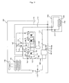
- FIG. 1 is a schematic view of an air conditioner in a heating mode according to an embodiment of the present invention
- FIG. 2 is a schematic diagram of the air conditioner of FIG. 1 , illustrating flow of refrigerant in the heating mode;
- FIG. 3 is a schematic diagram of an air conditioner in a cooling mode according to an embodiment of the present invention.
- FIG. 4 is a schematic diagram of the air conditioner of FIG. 3 , illustrating flow of refrigerant in the cooling mode
- FIG. 5 is a P-h diagram illustrating variation in enthalpy and pressure of refrigerant circulating an air conditioner according to an embodiment of the present invention.
- FIG. 6 is a flowchart illustrating an exemplary control method of an air conditioner according to an embodiment of the present invention.
- FIG. 1 is a schematic view of an air conditioner in a heating mode according to an embodiment of the present invention
- FIG. 2 is a schematic diagram of the air conditioner of FIG. 1 , illustrating flow of refrigerant in the heating mode.
- An embodiment of the present invention will be described hereinafter with reference to FIGS. 1 and 2 .
- An air conditioner includes an outdoor unit 100 and an indoor unit 200. Although one outdoor unit 100 and one indoor unit 200 are illustrated in the drawings, this should not be construed as a limitation. That is, the air conditioner may include a plurality of outdoor units 100 and/or a plurality of indoor units 200. When a plurality of outdoor units 100 are provided and interconnected, a high/low pressure common pipe 115 may be further provided to equalize the high pressure or low pressure refrigerant between the outdoor units 100.
- the outdoor unit 100 includes a compressor 120, an outdoor heat exchanger 130, and an internal heat exchanger 182. Although three compressors 120 are illustrated in this embodiment, this should not be construed as a limitation. The number of compressors may vary depending on an air conditioning load and compression capacity of the air conditioner.
- the compressor 120 includes an intake port 122 through which the refrigerant vaporized by the outdoor heat exchanger 130 flows into the compressor 120, a discharge port 124 through which the compressed refrigerant is discharged, and an injection port 126 through which the refrigerant that is in an intermediate pressure state is injected from the internal heat exchanger 182 side.
- the compressor 120 compresses low temperature/low pressure refrigerant into high temperature/high pressure refrigerant.
- the compressor 120 may be variously structured. For example, an inverter type compressor or a constant speed compressor may be used as the compressor 120.
- An accumulator 162 may be provided to prevent the liquid-phase refrigerant from flowing into the compressor 120.
- a temperature sensor 131 for measuring a temperature of the refrigerant discharged by the compressor 120 and a pressure switch 133 for adjusting discharge pressure of the refrigerant are provided.
- Oil contained in the refrigerant discharged by the compressor 120 is separated from the refrigerant by an oil separator 140 and the separated oil flows along the oil recovery pipe 141 and is mixed with the gas-phase refrigerant separated from the accumulator 162, after which the oil flows into the compressor 120.
- a capillary tube 137 may be provided in the oil recovery pipe 141.
- a four-way valve 172 that is a directional control valve functions to guide the refrigerant compressed in the compressor 120 to the outdoor heat exchanger 130 in a cooling mode and to the indoor heat exchanger 220 in a heating mode.
- the outdoor heat exchanger 130 is generally disposed outdoor.
- the refrigerant heat-exchanges with the outdoor air while passing through the outdoor heat exchanger 130.
- the outdoor heat exchanger 130 functions as a condenser in the cooling mode and as a vaporizer in the heating mode.
- the outdoor expansion valve 171 expands the refrigerant directed toward the outdoor heat exchanger 130 in the heating mode.
- a blower fan 178 may be provided to discharge heat generated by the heat-exchange between the outdoor air and the refrigerant flowing along the outdoor heat exchanger 178 external to the outdoor unit 100.
- the refrigerant condensed by the indoor heat exchanger 220 flows into the internal heat exchanger 182 through a liquid pipe 112.
- some of the refrigerant flowing along the liquid pipe 112 is directed to the bypass pipe 181 and expands while passing through an internal expansion valve 184 provided on the bypass pipe 181, after which the expanded refrigerant flows into the internal heat exchanger 182.
- heat exchange between the refrigerant from the liquid pipe 112 and the refrigerant from the bypass pipe 181 is realized at the internal heat exchanger 182.
- the refrigerant flowing from the liquid pipe 112 to the internal heat exchanger 182 has the higher temperature than the refrigerant flowing toward the bypass pipe 181 and expanded by the internal expansion valve 184.
- the expanded refrigerant absorbs the heat to be vaporized.
- the vaporized refrigerant is transferred to the compressor 120 through a first refrigerant pipe 111.
- a first temperature sensor 185 for measuring a temperature of the refrigerant injected toward the compressor 120 is provided.
- the first temperature sensor 185 may be provided on the first refrigerant pipe 111.
- a linear expansion valve may be used as the internal expansion valve 184 considering convenience in use and control.
- a first refrigerant adjusting valve 154 for controlling the refrigerant injected to the compressor 120 through the first refrigerant pipe 111 may be provided.
- the first refrigerant control valve 154 is controlled to be opened when degree of discharge superheat of the compressor is above a first predetermined value.
- the degree of superheat means a difference between a temperature of vaporized gas superheated above a saturated temperature and a saturated temperature corresponding to the pressure.
- the degree of discharge superheat of the compressor means a degree of superheat of the refrigerant discharged through a discharge port 124 of the compressor 120.
- the degree of discharge superheat may be measured in various ways. For example, it is possible to measure the degree of discharge superheat of the compressor 120 by detecting the discharge pressure and temperature of the compressor 120, which can be easily measured, and using a pressure-temperature curve corresponding to the detected discharge pressure and temperature. It is also possible to measure the degree of discharge superheat of the compressor by measuring a discharge temperature of the compressor 120 and a temperature of the refrigerant vaporized in the outdoor heat exchanger 130.
- the first predetermined value is a value for stable operation of the compressor 120.
- the degree of discharge superheat of the compressor 120 is too low, the liquid-phase refrigerant may flow into the compressor 120. This may be hard on the compressor 120 and may cause noise to be generated.
- the degree of discharge superheat of the compressor 120 is too high, the compressor 120 may be overheated and the efficiency of the compressor 120 may be deteriorated. Therefore, it is preferable that the first predetermined value is set considering these characteristics.
- a second refrigerant pipe 113 may be further provided so that the refrigerant flowing into the internal heat exchanger 182 through the bypass pipe 181 and heat-exchanged at the internal heat exchanger 182 can be transferred to the accumulator 162 in the cooling mode.
- a second refrigerant adjusting valve 156 may be provided on the second refrigerant pipe 113. The second refrigerant adjusting valve 156 may be controlled to be closed in the heating mode.
- the refrigerant flowing from the liquid pipe 112 to the internal heat exchanger 182 heat-exchanges with the refrigerant flowing along the bypass pipe 181, after which the refrigerant is discharged toward the outdoor heat exchanger 130.
- the refrigerant discharged toward the outdoor heat exchanger 130 expands while passing through the refrigerant expansion valve 171 before flowing into the outdoor heat exchanger 130.
- the refrigerant expanded by the refrigerant expansion valve 171 heat-exchanges while passing through the outdoor heat exchanger 130. At this point, it is preferable that the refrigerant is completely vaporized in the outdoor heat exchanger 130. However, the refrigerant may not be completely vaporized in the outdoor heat exchanger 130 due to a variety of conditions such as a temperature of outdoor air, pressure of the refrigerant, and temperature of the refrigerant. As a result, the refrigerant may exist in a state where liquid-phase refrigerant and gas-phase refrigerant are mixed with each other.
- the mixed refrigerant (the liquid-phase refrigerant and the gas-phase refrigerant) is separated into the gas-phase refrigerant and the liquid-phase refrigerant in the accumulator 162. At this point, the gas-phase refrigerant is returned to the compressor 120.
- the refrigerant injected through the first refrigerant pipe 111 and the refrigerant from the accumulator 162 are compressed together in the compressor 120. Therefore, a sufficient amount of the refrigerant being compressed can be attained and thus there is an effect that the heat efficiency can be improved.
- the refrigerant when a temperature of the outdoor air is low, the refrigerant may not be sufficiently vaporized in the outdoor heat exchanger 130 and thus both the gas-phase refrigerant and the liquid-phase refrigerant may be mixed and flow into the accumulator 162.
- the gas-phase refrigerant is separated in the accumulator 162 and flows into the compressor 120. Therefore, there was a problem that an amount of the gas-phase refrigerant flowing into the compressor 120 is reduced.
- a sufficient amount of the refrigerant flowing into the compressor 120 can be attained even when the temperature of the outdoor air is low.
- the air conditioner may further include a first temperature sensor 185 for measuring a temperature of refrigerant flowing along the first refrigerant pipe 111 and a second temperature sensor 183 for measuring the refrigerant flowing into the internal heat exchanger 182 through the bypass pipe 181.
- the second temperature sensor 183 may be provided between the internal heat exchanger 182 and the internal expansion valve 184.
- the degree of superheat (hereinafter, referred to as "degree of injection superheat") of the refrigerant injected into the compressor 120 can be represented by a difference between a temperature measured by the first temperature sensor 185 and a temperature measured by the second temperature sensor 183.
- An opening of the internal expansion valve 184 is adjusted such that the degree of injection superheat reaches a second predetermined value.
- the second predetermined value is set such that the degree of injection superheat can be sufficiently attained.
- the second predetermined value may be properly set considering the temperature of the outdoor air, performance of the compressor, endurance of the compressor and set value of the indoor temperature.
- the second predetermined value may be set to keep the degree of discharge superheat of the compressor 120 above the first predetermined value.
- the degree of discharge superheat of the compressor 120 may be lowered by a variety of conditions such as variation of outdoor temperature, the outdoor heat exchanger 130 in a low temperature environment, and freezing caused by the heat exchange in the outdoor heat exchanger 130 and internal heat exchanger 182.
- the second predetermined value can be properly set to keep the degree of discharge superheat of the compressor above the first predetermined value, thereby improving the heat performance and attaining the stability of the system.
- the second predetermined value may be set considering the temperature of the outdoor air.
- the second temperature should be set high.
- the indoor unit 200 may include an indoor expansion valve 210, an indoor heat exchanger 220, and an indoor blower fan 230 directing the heat-exchanged air toward the indoor space.
- the indoor expansion valve 210 is a device for expanding the refrigerant in the cooling mode. Although there is a variety of types of expansion valves, a linear expansion valve may be used as the indoor expansion valve 210 considering convenience in use and control. An opening of the indoor expansion valve 210 may be differently adjusted depending on whether it is in a cooling mode and in a heating mode.
- FIG. 3 is a schematic diagram of an air conditioner in a cooling mode according to an embodiment of the present invention
- FIG. 4 is a schematic diagram of the air conditioner of FIG. 3 , illustrating flow of refrigerant in the cooling mode. The flow of the refrigerant in the cooling mode will be described hereinafter with reference to FIGS. 3 and 4 .
- the high temperature/high pressure gas-phase refrigerant discharged from the compressor 120 flows into the outdoor heat exchanger 130 via the four-way valve 172.
- the refrigerant is condensed by heat-exchanging with the outdoor air.
- the refrigerant passing through the outdoor heat exchanger 130 does not flow into the refrigerant expansion valve 171 but is input to the internal heat exchanger 171 by detouring around the refrigerant expansion valve 171 through the refrigerant pipe 179.
- the refrigerant introduced into the internal heat exchanger 182 heat-exchanges and is then discharged to the liquid pipe 112.
- the refrigerant that is input from the bypass pipe 181 to the internal heat exchanger 182 and heat-exchanged is transferred to the accumulator 162 through the second refrigerant pipe 113.
- the liquid-phase refrigerant is removed from the refrigerant in the accumulator 162 and the refrigerant from which the liquid-phase refrigerant is removed is introduced into the compressor 120.
- the second refrigerant adjusting valve 156 may be provided on the second refrigerant pipe 113 and controlled to be opened in the cooling mode.
- the first refrigerant adjusting valve 154 provided on the first refrigerant adjusting valve 154 may be closed.
- a check valve 132 for preventing the refrigerant from flowing toward the compressor 120 may be provided on the first refrigerant pipe 111.
- the refrigerant flowing from the internal heat exchanger 182 to the liquid pipe 112 flows into the indoor unit 200 and is expanded by the indoor expansion valve 210, after which the refrigerant heat-exchanges at the indoor heat exchanger 220 and is then introduced into the compressor via the gas pipe 114, four-way valve 172, and accumulator 162 to continuously realize the cooling cycle.
- FIG. 5 is a P-h diagram illustrating variation in an enthalpy and pressure of refrigerant circulating in an air conditioner according to an embodiment of the present invention.
- the refrigerant flowing into the compressor 120 through the intake port 122 is compressed while varying in a phase thereof along "a-b" in the P-h diagram.
- the gas-phase refrigerant that heat-exchanged in the internal heat exchanger 182 is further injected into the compressor 120 through the injection port 126.
- the refrigerant flowing into the compressor 120 through the intake port 122 and the refrigerant injected through the injection port 126 are compressed together in the compressor 120.
- This process can be represented as a phase variation process along "c-d" in the P-h diagram.
- the refrigerant compressed by the compressor 120 and discharged from the compressor 120 flows into the indoor unit 200 and is condensed by heat-exchanging in the indoor heat exchanger 220. At this point, the phase of the refrigerant varies along "d-e" in the P-h diagram.
- This process can be represented as a phase variation process along "e-f" in the P-h diagram.
- the refrigerant output from the internal heat exchanger 182 to the outdoor heat exchanger 130 expands while passing through the refrigerant expansion valve 171.
- This process can be represented as a phase variation process along "f-g" in the P-h diagram.
- the refrigerant expanded by the refrigerant expansion valve 171 is input to the outdoor heat exchanger 130 and vaporized by heat-exchanging with the outdoor air.
- This process can be represented as a phase variation process along "g-a" in the P-h diagram.
- the refrigerant expanded by the internal expansion valve 184 is input again to the internal heat exchanger 182, after which the refrigerant is vaporized while heat-exchanging with the refrigerant input from the liquid pipe 112 to the internal heat exchanger 182.
- This process can be represented as a phase variation process along "h-c" in the P-h diagram.
- the refrigerant vaporized by heat-exchanging in the internal heat exchanger 182 is additionally injected into the compressor 120 and compressed by the compressor 120, much more refrigerant is compressed and thus the heating energy increases.
- a whole amount of energy (an amount proportional to an area defined by "a-b-c-d-e-f-g-a" in the P-h diagram) used for general heating increases by a process ("e-f" in the P-h diagram) where the refrigerant flowing from the liquid pipe 112 to the internal heat exchanger 182 is condensed while heat-exchanging with the refrigerant input to the internal heat exchanger 182 through the bypass pipe 181.
- the heating increase rate can be defined by a ratio between Pd-Pm and Pd-Ps as follows:
- n Pd ⁇ Pm / Pd ⁇ Ps ;
- Pd pressure of the refrigerant discharged by the compressor 120, which can be measured by a pressure sensor 187 measuring pressure at an front end of the discharge port 124
- Pm pressure of the refrigerant flowing into the compressor 120 through the injection port 126, which can be measured by a pressure sensor 186 provided on the first refrigerant pipe 111
- Ps is pressure introduced into the intake port 122, which can be measured by a pressure sensor 188.
- a pressure adjusting unit may be provided near the discharge port 124 of the compressor 120.
- a pressure switch 133 may be provided on the front end of the discharge port 124 of the compressor as the pressure adjusting unit.
- a pressure switch (not shown) may be provided on the first refrigerant pipe 111 to adjust the pressure Pm of the refrigerant injected to the compressor 120 through the injection port 126.
- An additional pressure switch (now shown) may be provided to adjust the pressure of the refrigerant flowing into the compressor 120 through the intake port 122.
- the opening of the internal expansion valve 184 it is also possible to adjust the opening of the internal expansion valve 184 to maintain the heat increasing rate (n) within a predetermined range. That is, by adjusting the opening of the internal expansion valve 184, the degree of superheat of the refrigerant injected into the compressor 120 through the injection port 126 can be controlled and thus the heating increase rate (n) determined by the pressures Pd, Ps, and Pm that vary in response to the degree of superheat of the refrigerant.
- FIG. 6 is a flowchart illustrating an exemplary control method of an air conditioner according to an embodiment of the present invention, which may be performed by a controller.
- the heating mode operation is performed (S10).
- the degree of discharge superheat of the compressor 120 is measured (S20).
- the predetermined time is a time for which the system can be stabilized. That is, when the degree of discharge superheat of the compressor 120 is too low, the refrigerant flowing into the compressor 120 may contain the liquid-phase refrigerant. This may cause operational noise to be generated. The operational noise may cause user complaint. On the other hand, when the degree of discharge superheat of the compressor 120 is too high, the compressor 120 may burn out. Therefore, the predetermined time may be set considering the above-described characteristics.
- the first predetermined value may be set considering the above-described characteristics for the stability of the system.
- the first refrigerant adjusting valve 154 When the degree of discharge superheat is above the first predetermined value, the first refrigerant adjusting valve 154 is opened to allow for a refrigerant passage from the internal heat exchanger 182 to the compressor 120 (S40). At this point, some of the refrigerant input from the indoor heat exchanger 220 to the internal heat exchanger 182 along the liquid pipe 112 is branched off to the bypass pipe 181 and expands while passing through the internal expansion valve 184.
- the expanded refrigerant heat-exchanges with the rest of the refrigerant input to the internal heat exchanger 182 along the liquid pipe 112. At this point, the refrigerant vaporized by the heat exchange is injected into the compressor 120 through the injection port 126 along the first refrigerant pipe 111.
- the first and second temperature sensors 185 and 183 measure a first temperature T1 injected to the compressor 120 and a temperature T2 expanded by the internal expansion valve 184 and input to the internal heat exchanger 182 to measure the degree of injection superheat, respectively (S50).
- the opening of the internal expansion valve 184 is adjusted in accordance with the degree of discharge superheat and/or degree of injection superheat of the compressor 120 (S60). Next, the degree of injection superheat is compared with a second predetermined value (S70). When the degree of injection superheat is lower than the second predetermined value, the opening of the internal expansion valve 184 is adjusted again to make the degree of injection superheat higher than the second predetermined value.
- a condensing temperature (T3) of the refrigerant flowing into the compressor 120 is measured (S80).
- the condensing temperature may be a temperature for condensing the refrigerant in the indoor heat exchanger 220.
- the temperatures (T1 and T2) are measured again (S50) to continuously control the degree of injection superheat.
- the condensing temperature (T3) is a reference temperature by which it is determined if the system is stabilized to a state where no refrigerant injection is required any more. Therefore, the condensing temperature (T3) may be set based on a condensing temperature in the internal heat exchanger 182.
- the second predetermined value is a value affecting on the degree of discharge superheat of the compressor.
- the second predetermined value may be set to maintain the degree of discharge superheat of the compressor above the first predetermined value.
- the degree of injection superheat is above the second predetermined value by adjusting the opening of the internal expansion valve 184, the degree of discharge superheat will be also above the first predetermined value consequently.
- the pressure of the refrigerant discharged by the compressor 120 may be adjusted such that the heating increase rate (n) that is a ratio between a difference between the pressure Pd of the refrigerant discharged by the compressor 120 and the pressure Ps of the refrigerant introduced into the compressor and a difference between the pressure Pd of the refrigerant discharged by the compressor 120 and the pressure Ps of the refrigerant injected to the compressor 120 can be within a predetermined range.
- the pressure of the refrigerant discharged by the compressor 120 can be adjusted by the pressure switch 133.
- the heating increase rate (n) may be controlled by adjusting the opening of the internal expansion valve 184. That is, the pressures Pd, Pm, and Ps that vary by adjustment of the opening of the internal expansion valve 184 are detected and the opening of the internal expansion valve 184 is corrected in accordance with the detected pressures Pd, Pm, and Ps, thereby controlling the heating increase rate (n) within the predetermined range.
Landscapes
- Engineering & Computer Science (AREA)
- Physics & Mathematics (AREA)
- Mechanical Engineering (AREA)
- Thermal Sciences (AREA)
- General Engineering & Computer Science (AREA)
- Chemical & Material Sciences (AREA)
- Analytical Chemistry (AREA)
- Power Engineering (AREA)
- Compression-Type Refrigeration Machines With Reversible Cycles (AREA)
- Air Conditioning Control Device (AREA)
Applications Claiming Priority (1)
| Application Number | Priority Date | Filing Date | Title |
|---|---|---|---|
| KR1020090015927A KR101552618B1 (ko) | 2009-02-25 | 2009-02-25 | 공기 조화기 |
Publications (3)
| Publication Number | Publication Date |
|---|---|
| EP2224191A2 true EP2224191A2 (fr) | 2010-09-01 |
| EP2224191A3 EP2224191A3 (fr) | 2012-01-11 |
| EP2224191B1 EP2224191B1 (fr) | 2016-12-28 |
Family
ID=42235666
Family Applications (1)
| Application Number | Title | Priority Date | Filing Date |
|---|---|---|---|
| EP10001897.7A Not-in-force EP2224191B1 (fr) | 2009-02-25 | 2010-02-24 | Climatiseur et procédé de commande correspondant |
Country Status (4)
| Country | Link |
|---|---|
| US (1) | US8459051B2 (fr) |
| EP (1) | EP2224191B1 (fr) |
| KR (1) | KR101552618B1 (fr) |
| ES (1) | ES2619706T3 (fr) |
Cited By (5)
| Publication number | Priority date | Publication date | Assignee | Title |
|---|---|---|---|---|
| CN104613665A (zh) * | 2015-02-02 | 2015-05-13 | 珠海格力电器股份有限公司 | 热泵空调系统 |
| EP2778567A4 (fr) * | 2011-11-07 | 2015-07-08 | Mitsubishi Electric Corp | Appareil de climatisation |
| CN104896813A (zh) * | 2015-06-29 | 2015-09-09 | 广东美的暖通设备有限公司 | 用于空调的多联机系统 |
| WO2017206106A1 (fr) * | 2016-06-01 | 2017-12-07 | 唐玉敏 | Système d'échange de chaleur |
| EP3382300A1 (fr) * | 2017-03-31 | 2018-10-03 | Mitsubishi Electric R&D Centre Europe B.V. | Système de cycle de chauffage et/ou de refroidissement et procédé de fonctionnement de chauffage et/ou de refroidissement |
Families Citing this family (18)
| Publication number | Priority date | Publication date | Assignee | Title |
|---|---|---|---|---|
| JP5484930B2 (ja) | 2010-01-25 | 2014-05-07 | 三菱重工業株式会社 | 空気調和機 |
| JP5240332B2 (ja) * | 2011-09-01 | 2013-07-17 | ダイキン工業株式会社 | 冷凍装置 |
| EP2787305B1 (fr) * | 2011-11-29 | 2019-09-04 | Mitsubishi Electric Corporation | Dispositif de réfrigération/climatisation |
| KR102122258B1 (ko) * | 2013-12-31 | 2020-06-12 | 엘지전자 주식회사 | 공기조화기 |
| KR102242776B1 (ko) * | 2014-03-20 | 2021-04-20 | 엘지전자 주식회사 | 공기조화기 및 그 제어방법 |
| KR102242777B1 (ko) * | 2014-03-20 | 2021-04-20 | 엘지전자 주식회사 | 공기조화기 |
| JP6242321B2 (ja) * | 2014-10-03 | 2017-12-06 | 三菱電機株式会社 | 空気調和機 |
| KR101854335B1 (ko) * | 2016-01-18 | 2018-05-03 | 엘지전자 주식회사 | 공기조화기 |
| US10801762B2 (en) | 2016-02-18 | 2020-10-13 | Emerson Climate Technologies, Inc. | Compressor floodback protection system |
| CN107356012A (zh) | 2016-05-09 | 2017-11-17 | 开利公司 | 热泵系统及其控制方法 |
| US20220228767A1 (en) * | 2016-10-17 | 2022-07-21 | Gree Electric Appliances, Inc. Of Zhuhai | Air Conditioner, Control Method and Control Device Thereof |
| CN106766444B (zh) * | 2016-11-17 | 2019-10-01 | 广东美的暖通设备有限公司 | 空调系统的防液击控制方法和控制装置及空调系统 |
| CN107192159A (zh) * | 2017-07-11 | 2017-09-22 | 南京天加环境科技有限公司 | 一种改进的补气增焓冷热机组 |
| CN111954787B (zh) * | 2018-04-16 | 2023-06-27 | 开利公司 | 双压缩机式热泵 |
| JP7162173B2 (ja) * | 2019-03-28 | 2022-10-28 | パナソニックIpマネジメント株式会社 | 空気調和装置 |
| CN110057132A (zh) * | 2019-04-30 | 2019-07-26 | 广东美的制冷设备有限公司 | 冷媒系统和空调器 |
| WO2020257966A1 (fr) * | 2019-06-24 | 2020-12-30 | 广东美芝精密制造有限公司 | Compresseur et système d'échange de chaleur |
| WO2021082331A1 (fr) * | 2019-10-28 | 2021-05-06 | 广东美的制冷设备有限公司 | Climatiseur |
Citations (7)
| Publication number | Priority date | Publication date | Assignee | Title |
|---|---|---|---|---|
| US4938029A (en) | 1989-07-03 | 1990-07-03 | Carrier Corporation | Unloading system for two-stage compressors |
| EP0778451A2 (fr) | 1995-12-06 | 1997-06-11 | Carrier Corporation | Refroidissement de moteur dans un système frigorifique |
| JPH09210480A (ja) | 1996-01-31 | 1997-08-12 | Mitsubishi Heavy Ind Ltd | 二段圧縮式冷凍装置 |
| JP2000234811A (ja) | 1999-02-17 | 2000-08-29 | Matsushita Electric Ind Co Ltd | 冷凍サイクル装置 |
| US20030010046A1 (en) | 2001-07-11 | 2003-01-16 | Thermo King Corporation | Method for operating a refrigeration unit |
| JP2007255864A (ja) | 2006-03-27 | 2007-10-04 | Mitsubishi Electric Corp | 二段圧縮式冷凍装置 |
| US20090044550A1 (en) | 2005-12-16 | 2009-02-19 | Daikin Industries, Ltd. | Air conditioner |
Family Cites Families (10)
| Publication number | Priority date | Publication date | Assignee | Title |
|---|---|---|---|---|
| JPS61174295A (ja) | 1985-01-28 | 1986-08-05 | Sumikin Coke Co Ltd | タール酸の精製方法 |
| JPH02309157A (ja) | 1989-05-24 | 1990-12-25 | Matsushita Electric Ind Co Ltd | 二段圧縮冷凍サイクル装置とその運転方法 |
| JP2000018737A (ja) | 1998-06-24 | 2000-01-18 | Daikin Ind Ltd | 空気調和機 |
| EP1225400B1 (fr) | 1999-10-18 | 2007-12-12 | Daikin Industries, Ltd. | Dispositif de refrigeration |
| US6474087B1 (en) | 2001-10-03 | 2002-11-05 | Carrier Corporation | Method and apparatus for the control of economizer circuit flow for optimum performance |
| JP4442237B2 (ja) * | 2004-01-30 | 2010-03-31 | 三菱電機株式会社 | 空気調和装置 |
| US20060064997A1 (en) * | 2004-09-29 | 2006-03-30 | Grabon Michal K | Cooling systems |
| JP4771721B2 (ja) * | 2005-03-16 | 2011-09-14 | 三菱電機株式会社 | 空気調和装置 |
| JP2008106738A (ja) | 2006-09-29 | 2008-05-08 | Fujitsu General Ltd | ロータリ圧縮機およびヒートポンプシステム |
| US7997092B2 (en) * | 2007-09-26 | 2011-08-16 | Carrier Corporation | Refrigerant vapor compression system operating at or near zero load |
-
2009
- 2009-02-25 KR KR1020090015927A patent/KR101552618B1/ko active IP Right Grant
-
2010
- 2010-02-23 US US12/710,886 patent/US8459051B2/en active Active
- 2010-02-24 EP EP10001897.7A patent/EP2224191B1/fr not_active Not-in-force
- 2010-02-24 ES ES10001897.7T patent/ES2619706T3/es active Active
Patent Citations (7)
| Publication number | Priority date | Publication date | Assignee | Title |
|---|---|---|---|---|
| US4938029A (en) | 1989-07-03 | 1990-07-03 | Carrier Corporation | Unloading system for two-stage compressors |
| EP0778451A2 (fr) | 1995-12-06 | 1997-06-11 | Carrier Corporation | Refroidissement de moteur dans un système frigorifique |
| JPH09210480A (ja) | 1996-01-31 | 1997-08-12 | Mitsubishi Heavy Ind Ltd | 二段圧縮式冷凍装置 |
| JP2000234811A (ja) | 1999-02-17 | 2000-08-29 | Matsushita Electric Ind Co Ltd | 冷凍サイクル装置 |
| US20030010046A1 (en) | 2001-07-11 | 2003-01-16 | Thermo King Corporation | Method for operating a refrigeration unit |
| US20090044550A1 (en) | 2005-12-16 | 2009-02-19 | Daikin Industries, Ltd. | Air conditioner |
| JP2007255864A (ja) | 2006-03-27 | 2007-10-04 | Mitsubishi Electric Corp | 二段圧縮式冷凍装置 |
Cited By (6)
| Publication number | Priority date | Publication date | Assignee | Title |
|---|---|---|---|---|
| EP2778567A4 (fr) * | 2011-11-07 | 2015-07-08 | Mitsubishi Electric Corp | Appareil de climatisation |
| US9797610B2 (en) | 2011-11-07 | 2017-10-24 | Mitsubishi Electric Corporation | Air-conditioning apparatus with regulation of injection flow rate |
| CN104613665A (zh) * | 2015-02-02 | 2015-05-13 | 珠海格力电器股份有限公司 | 热泵空调系统 |
| CN104896813A (zh) * | 2015-06-29 | 2015-09-09 | 广东美的暖通设备有限公司 | 用于空调的多联机系统 |
| WO2017206106A1 (fr) * | 2016-06-01 | 2017-12-07 | 唐玉敏 | Système d'échange de chaleur |
| EP3382300A1 (fr) * | 2017-03-31 | 2018-10-03 | Mitsubishi Electric R&D Centre Europe B.V. | Système de cycle de chauffage et/ou de refroidissement et procédé de fonctionnement de chauffage et/ou de refroidissement |
Also Published As
| Publication number | Publication date |
|---|---|
| EP2224191A3 (fr) | 2012-01-11 |
| EP2224191B1 (fr) | 2016-12-28 |
| US20100212342A1 (en) | 2010-08-26 |
| ES2619706T3 (es) | 2017-06-26 |
| US8459051B2 (en) | 2013-06-11 |
| KR101552618B1 (ko) | 2015-09-11 |
| KR20100096858A (ko) | 2010-09-02 |
Similar Documents
| Publication | Publication Date | Title |
|---|---|---|
| US8459051B2 (en) | Air conditioner and method of controlling the same | |
| CN108027179B (zh) | 空气调节机 | |
| US8353173B2 (en) | Refrigerating cycle apparatus and operation control method therefor | |
| KR101605901B1 (ko) | 공기 조화기 및 그 제어방법 | |
| CN105371545B (zh) | 空调器及其制冷系统的制冷剂循环量调节方法 | |
| US9151522B2 (en) | Air conditioner and control method thereof | |
| JP5213817B2 (ja) | 空気調和機 | |
| JP6223469B2 (ja) | 空気調和装置 | |
| US20100206000A1 (en) | Air conditioner and method of controlling the same | |
| EP3483524A1 (fr) | Dispositif de commande de dispositif de conditionnement d'air de type multiple, dispositif de conditionnement d'air de type multiple, procédé de commande de dispositif de conditionnement d'air de type multiple et programme informatique de commande de dispositif de conditionnement d'air de type multiple | |
| US20200256590A1 (en) | Refrigeration cycle apparatus | |
| JP6594599B1 (ja) | 空気調和装置 | |
| JP2005076933A (ja) | 冷凍サイクル装置 | |
| KR20080069824A (ko) | 공기조화기의 과열도 제어시스템 및 그 방법 | |
| US8205463B2 (en) | Air conditioner and method of controlling the same | |
| JP5213372B2 (ja) | 空気調和機 | |
| KR101414860B1 (ko) | 공기 조화기 및 그의 제어방법 | |
| JP7112057B1 (ja) | 空気調和装置 | |
| JP6846915B2 (ja) | 多室型空気調和機 | |
| KR20110062455A (ko) | 공기조화 시스템 | |
| JP5517891B2 (ja) | 空気調和装置 | |
| JP2017101857A (ja) | 冷凍装置 | |
| JP7224503B2 (ja) | 冷凍サイクル装置 | |
| JP2018146169A (ja) | 空調機 | |
| JP6105271B2 (ja) | 空気調和機 |
Legal Events
| Date | Code | Title | Description |
|---|---|---|---|
| PUAI | Public reference made under article 153(3) epc to a published international application that has entered the european phase |
Free format text: ORIGINAL CODE: 0009012 |
|
| AK | Designated contracting states |
Kind code of ref document: A2 Designated state(s): AT BE BG CH CY CZ DE DK EE ES FI FR GB GR HR HU IE IS IT LI LT LU LV MC MK MT NL NO PL PT RO SE SI SK SM TR |
|
| AX | Request for extension of the european patent |
Extension state: AL BA RS |
|
| PUAL | Search report despatched |
Free format text: ORIGINAL CODE: 0009013 |
|
| AK | Designated contracting states |
Kind code of ref document: A3 Designated state(s): AT BE BG CH CY CZ DE DK EE ES FI FR GB GR HR HU IE IS IT LI LT LU LV MC MK MT NL NO PL PT RO SE SI SK SM TR |
|
| AX | Request for extension of the european patent |
Extension state: AL BA RS |
|
| RIC1 | Information provided on ipc code assigned before grant |
Ipc: F25B 13/00 20060101ALN20111208BHEP Ipc: F25B 41/00 20060101AFI20111208BHEP |
|
| 17P | Request for examination filed |
Effective date: 20120709 |
|
| GRAP | Despatch of communication of intention to grant a patent |
Free format text: ORIGINAL CODE: EPIDOSNIGR1 |
|
| INTG | Intention to grant announced |
Effective date: 20160712 |
|
| RAP1 | Party data changed (applicant data changed or rights of an application transferred) |
Owner name: LG ELECTRONICS INC. |
|
| GRAS | Grant fee paid |
Free format text: ORIGINAL CODE: EPIDOSNIGR3 |
|
| GRAA | (expected) grant |
Free format text: ORIGINAL CODE: 0009210 |
|
| AK | Designated contracting states |
Kind code of ref document: B1 Designated state(s): AT BE BG CH CY CZ DE DK EE ES FI FR GB GR HR HU IE IS IT LI LT LU LV MC MK MT NL NO PL PT RO SE SI SK SM TR |
|
| REG | Reference to a national code |
Ref country code: GB Ref legal event code: FG4D |
|
| REG | Reference to a national code |
Ref country code: CH Ref legal event code: EP |
|
| REG | Reference to a national code |
Ref country code: AT Ref legal event code: REF Ref document number: 857653 Country of ref document: AT Kind code of ref document: T Effective date: 20170115 |
|
| REG | Reference to a national code |
Ref country code: IE Ref legal event code: FG4D |
|
| REG | Reference to a national code |
Ref country code: DE Ref legal event code: R096 Ref document number: 602010039084 Country of ref document: DE |
|
| REG | Reference to a national code |
Ref country code: FR Ref legal event code: PLFP Year of fee payment: 8 |
|
| PG25 | Lapsed in a contracting state [announced via postgrant information from national office to epo] |
Ref country code: LV Free format text: LAPSE BECAUSE OF FAILURE TO SUBMIT A TRANSLATION OF THE DESCRIPTION OR TO PAY THE FEE WITHIN THE PRESCRIBED TIME-LIMIT Effective date: 20161228 |
|
| REG | Reference to a national code |
Ref country code: LT Ref legal event code: MG4D |
|
| PG25 | Lapsed in a contracting state [announced via postgrant information from national office to epo] |
Ref country code: GR Free format text: LAPSE BECAUSE OF FAILURE TO SUBMIT A TRANSLATION OF THE DESCRIPTION OR TO PAY THE FEE WITHIN THE PRESCRIBED TIME-LIMIT Effective date: 20170329 Ref country code: NO Free format text: LAPSE BECAUSE OF FAILURE TO SUBMIT A TRANSLATION OF THE DESCRIPTION OR TO PAY THE FEE WITHIN THE PRESCRIBED TIME-LIMIT Effective date: 20170328 Ref country code: LT Free format text: LAPSE BECAUSE OF FAILURE TO SUBMIT A TRANSLATION OF THE DESCRIPTION OR TO PAY THE FEE WITHIN THE PRESCRIBED TIME-LIMIT Effective date: 20161228 Ref country code: SE Free format text: LAPSE BECAUSE OF FAILURE TO SUBMIT A TRANSLATION OF THE DESCRIPTION OR TO PAY THE FEE WITHIN THE PRESCRIBED TIME-LIMIT Effective date: 20161228 |
|
| REG | Reference to a national code |
Ref country code: NL Ref legal event code: MP Effective date: 20161228 |
|
| REG | Reference to a national code |
Ref country code: AT Ref legal event code: MK05 Ref document number: 857653 Country of ref document: AT Kind code of ref document: T Effective date: 20161228 |
|
| PG25 | Lapsed in a contracting state [announced via postgrant information from national office to epo] |
Ref country code: FI Free format text: LAPSE BECAUSE OF FAILURE TO SUBMIT A TRANSLATION OF THE DESCRIPTION OR TO PAY THE FEE WITHIN THE PRESCRIBED TIME-LIMIT Effective date: 20161228 Ref country code: HR Free format text: LAPSE BECAUSE OF FAILURE TO SUBMIT A TRANSLATION OF THE DESCRIPTION OR TO PAY THE FEE WITHIN THE PRESCRIBED TIME-LIMIT Effective date: 20161228 Ref country code: BE Free format text: LAPSE BECAUSE OF NON-PAYMENT OF DUE FEES Effective date: 20170228 |
|
| REG | Reference to a national code |
Ref country code: ES Ref legal event code: FG2A Ref document number: 2619706 Country of ref document: ES Kind code of ref document: T3 Effective date: 20170626 |
|
| PG25 | Lapsed in a contracting state [announced via postgrant information from national office to epo] |
Ref country code: NL Free format text: LAPSE BECAUSE OF FAILURE TO SUBMIT A TRANSLATION OF THE DESCRIPTION OR TO PAY THE FEE WITHIN THE PRESCRIBED TIME-LIMIT Effective date: 20161228 |
|
| PG25 | Lapsed in a contracting state [announced via postgrant information from national office to epo] |
Ref country code: IS Free format text: LAPSE BECAUSE OF FAILURE TO SUBMIT A TRANSLATION OF THE DESCRIPTION OR TO PAY THE FEE WITHIN THE PRESCRIBED TIME-LIMIT Effective date: 20170428 Ref country code: SK Free format text: LAPSE BECAUSE OF FAILURE TO SUBMIT A TRANSLATION OF THE DESCRIPTION OR TO PAY THE FEE WITHIN THE PRESCRIBED TIME-LIMIT Effective date: 20161228 Ref country code: CZ Free format text: LAPSE BECAUSE OF FAILURE TO SUBMIT A TRANSLATION OF THE DESCRIPTION OR TO PAY THE FEE WITHIN THE PRESCRIBED TIME-LIMIT Effective date: 20161228 Ref country code: EE Free format text: LAPSE BECAUSE OF FAILURE TO SUBMIT A TRANSLATION OF THE DESCRIPTION OR TO PAY THE FEE WITHIN THE PRESCRIBED TIME-LIMIT Effective date: 20161228 Ref country code: RO Free format text: LAPSE BECAUSE OF FAILURE TO SUBMIT A TRANSLATION OF THE DESCRIPTION OR TO PAY THE FEE WITHIN THE PRESCRIBED TIME-LIMIT Effective date: 20161228 |
|
| PG25 | Lapsed in a contracting state [announced via postgrant information from national office to epo] |
Ref country code: SM Free format text: LAPSE BECAUSE OF FAILURE TO SUBMIT A TRANSLATION OF THE DESCRIPTION OR TO PAY THE FEE WITHIN THE PRESCRIBED TIME-LIMIT Effective date: 20161228 Ref country code: AT Free format text: LAPSE BECAUSE OF FAILURE TO SUBMIT A TRANSLATION OF THE DESCRIPTION OR TO PAY THE FEE WITHIN THE PRESCRIBED TIME-LIMIT Effective date: 20161228 Ref country code: PL Free format text: LAPSE BECAUSE OF FAILURE TO SUBMIT A TRANSLATION OF THE DESCRIPTION OR TO PAY THE FEE WITHIN THE PRESCRIBED TIME-LIMIT Effective date: 20161228 Ref country code: IT Free format text: LAPSE BECAUSE OF FAILURE TO SUBMIT A TRANSLATION OF THE DESCRIPTION OR TO PAY THE FEE WITHIN THE PRESCRIBED TIME-LIMIT Effective date: 20161228 Ref country code: BE Free format text: LAPSE BECAUSE OF FAILURE TO SUBMIT A TRANSLATION OF THE DESCRIPTION OR TO PAY THE FEE WITHIN THE PRESCRIBED TIME-LIMIT Effective date: 20161228 Ref country code: PT Free format text: LAPSE BECAUSE OF FAILURE TO SUBMIT A TRANSLATION OF THE DESCRIPTION OR TO PAY THE FEE WITHIN THE PRESCRIBED TIME-LIMIT Effective date: 20170428 Ref country code: BG Free format text: LAPSE BECAUSE OF FAILURE TO SUBMIT A TRANSLATION OF THE DESCRIPTION OR TO PAY THE FEE WITHIN THE PRESCRIBED TIME-LIMIT Effective date: 20170328 |
|
| REG | Reference to a national code |
Ref country code: DE Ref legal event code: R119 Ref document number: 602010039084 Country of ref document: DE |
|
| PG25 | Lapsed in a contracting state [announced via postgrant information from national office to epo] |
Ref country code: MC Free format text: LAPSE BECAUSE OF FAILURE TO SUBMIT A TRANSLATION OF THE DESCRIPTION OR TO PAY THE FEE WITHIN THE PRESCRIBED TIME-LIMIT Effective date: 20161228 |
|
| REG | Reference to a national code |
Ref country code: CH Ref legal event code: PL |
|
| PG25 | Lapsed in a contracting state [announced via postgrant information from national office to epo] |
Ref country code: LI Free format text: LAPSE BECAUSE OF NON-PAYMENT OF DUE FEES Effective date: 20170228 Ref country code: CH Free format text: LAPSE BECAUSE OF NON-PAYMENT OF DUE FEES Effective date: 20170228 |
|
| PLBE | No opposition filed within time limit |
Free format text: ORIGINAL CODE: 0009261 |
|
| STAA | Information on the status of an ep patent application or granted ep patent |
Free format text: STATUS: NO OPPOSITION FILED WITHIN TIME LIMIT |
|
| GBPC | Gb: european patent ceased through non-payment of renewal fee |
Effective date: 20170328 |
|
| REG | Reference to a national code |
Ref country code: IE Ref legal event code: MM4A |
|
| PG25 | Lapsed in a contracting state [announced via postgrant information from national office to epo] |
Ref country code: DK Free format text: LAPSE BECAUSE OF FAILURE TO SUBMIT A TRANSLATION OF THE DESCRIPTION OR TO PAY THE FEE WITHIN THE PRESCRIBED TIME-LIMIT Effective date: 20161228 |
|
| 26N | No opposition filed |
Effective date: 20170929 |
|
| PG25 | Lapsed in a contracting state [announced via postgrant information from national office to epo] |
Ref country code: LU Free format text: LAPSE BECAUSE OF NON-PAYMENT OF DUE FEES Effective date: 20170224 |
|
| REG | Reference to a national code |
Ref country code: FR Ref legal event code: PLFP Year of fee payment: 9 |
|
| PG25 | Lapsed in a contracting state [announced via postgrant information from national office to epo] |
Ref country code: DE Free format text: LAPSE BECAUSE OF NON-PAYMENT OF DUE FEES Effective date: 20170901 |
|
| PG25 | Lapsed in a contracting state [announced via postgrant information from national office to epo] |
Ref country code: GB Free format text: LAPSE BECAUSE OF NON-PAYMENT OF DUE FEES Effective date: 20170328 Ref country code: SI Free format text: LAPSE BECAUSE OF FAILURE TO SUBMIT A TRANSLATION OF THE DESCRIPTION OR TO PAY THE FEE WITHIN THE PRESCRIBED TIME-LIMIT Effective date: 20161228 Ref country code: IE Free format text: LAPSE BECAUSE OF NON-PAYMENT OF DUE FEES Effective date: 20170224 |
|
| PG25 | Lapsed in a contracting state [announced via postgrant information from national office to epo] |
Ref country code: MT Free format text: LAPSE BECAUSE OF NON-PAYMENT OF DUE FEES Effective date: 20170224 |
|
| PGFP | Annual fee paid to national office [announced via postgrant information from national office to epo] |
Ref country code: ES Payment date: 20190313 Year of fee payment: 10 |
|
| PG25 | Lapsed in a contracting state [announced via postgrant information from national office to epo] |
Ref country code: HU Free format text: LAPSE BECAUSE OF FAILURE TO SUBMIT A TRANSLATION OF THE DESCRIPTION OR TO PAY THE FEE WITHIN THE PRESCRIBED TIME-LIMIT; INVALID AB INITIO Effective date: 20100224 |
|
| PG25 | Lapsed in a contracting state [announced via postgrant information from national office to epo] |
Ref country code: CY Free format text: LAPSE BECAUSE OF NON-PAYMENT OF DUE FEES Effective date: 20161228 |
|
| PG25 | Lapsed in a contracting state [announced via postgrant information from national office to epo] |
Ref country code: MK Free format text: LAPSE BECAUSE OF FAILURE TO SUBMIT A TRANSLATION OF THE DESCRIPTION OR TO PAY THE FEE WITHIN THE PRESCRIBED TIME-LIMIT Effective date: 20161228 |
|
| PG25 | Lapsed in a contracting state [announced via postgrant information from national office to epo] |
Ref country code: TR Free format text: LAPSE BECAUSE OF FAILURE TO SUBMIT A TRANSLATION OF THE DESCRIPTION OR TO PAY THE FEE WITHIN THE PRESCRIBED TIME-LIMIT Effective date: 20161228 |
|
| PGFP | Annual fee paid to national office [announced via postgrant information from national office to epo] |
Ref country code: FR Payment date: 20200108 Year of fee payment: 11 |
|
| PG25 | Lapsed in a contracting state [announced via postgrant information from national office to epo] |
Ref country code: ES Free format text: LAPSE BECAUSE OF NON-PAYMENT OF DUE FEES Effective date: 20200225 |
|
| PG25 | Lapsed in a contracting state [announced via postgrant information from national office to epo] |
Ref country code: FR Free format text: LAPSE BECAUSE OF NON-PAYMENT OF DUE FEES Effective date: 20210228 |