EP2222248B1 - Cardiac valve downsizing device - Google Patents
Cardiac valve downsizing device Download PDFInfo
- Publication number
- EP2222248B1 EP2222248B1 EP08865711.9A EP08865711A EP2222248B1 EP 2222248 B1 EP2222248 B1 EP 2222248B1 EP 08865711 A EP08865711 A EP 08865711A EP 2222248 B1 EP2222248 B1 EP 2222248B1
- Authority
- EP
- European Patent Office
- Prior art keywords
- valve
- medical device
- downsizing
- heart
- annulus
- Prior art date
- Legal status (The legal status is an assumption and is not a legal conclusion. Google has not performed a legal analysis and makes no representation as to the accuracy of the status listed.)
- Revoked
Links
Images


Classifications
-
- A—HUMAN NECESSITIES
- A61—MEDICAL OR VETERINARY SCIENCE; HYGIENE
- A61F—FILTERS IMPLANTABLE INTO BLOOD VESSELS; PROSTHESES; DEVICES PROVIDING PATENCY TO, OR PREVENTING COLLAPSING OF, TUBULAR STRUCTURES OF THE BODY, e.g. STENTS; ORTHOPAEDIC, NURSING OR CONTRACEPTIVE DEVICES; FOMENTATION; TREATMENT OR PROTECTION OF EYES OR EARS; BANDAGES, DRESSINGS OR ABSORBENT PADS; FIRST-AID KITS
- A61F2/00—Filters implantable into blood vessels; Prostheses, i.e. artificial substitutes or replacements for parts of the body; Appliances for connecting them with the body; Devices providing patency to, or preventing collapsing of, tubular structures of the body, e.g. stents
- A61F2/02—Prostheses implantable into the body
- A61F2/24—Heart valves ; Vascular valves, e.g. venous valves; Heart implants, e.g. passive devices for improving the function of the native valve or the heart muscle; Transmyocardial revascularisation [TMR] devices; Valves implantable in the body
- A61F2/2442—Annuloplasty rings or inserts for correcting the valve shape; Implants for improving the function of a native heart valve
- A61F2/2445—Annuloplasty rings in direct contact with the valve annulus
-
- A—HUMAN NECESSITIES
- A61—MEDICAL OR VETERINARY SCIENCE; HYGIENE
- A61B—DIAGNOSIS; SURGERY; IDENTIFICATION
- A61B17/00—Surgical instruments, devices or methods, e.g. tourniquets
- A61B17/12—Surgical instruments, devices or methods, e.g. tourniquets for ligaturing or otherwise compressing tubular parts of the body, e.g. blood vessels, umbilical cord
-
- A—HUMAN NECESSITIES
- A61—MEDICAL OR VETERINARY SCIENCE; HYGIENE
- A61F—FILTERS IMPLANTABLE INTO BLOOD VESSELS; PROSTHESES; DEVICES PROVIDING PATENCY TO, OR PREVENTING COLLAPSING OF, TUBULAR STRUCTURES OF THE BODY, e.g. STENTS; ORTHOPAEDIC, NURSING OR CONTRACEPTIVE DEVICES; FOMENTATION; TREATMENT OR PROTECTION OF EYES OR EARS; BANDAGES, DRESSINGS OR ABSORBENT PADS; FIRST-AID KITS
- A61F2/00—Filters implantable into blood vessels; Prostheses, i.e. artificial substitutes or replacements for parts of the body; Appliances for connecting them with the body; Devices providing patency to, or preventing collapsing of, tubular structures of the body, e.g. stents
- A61F2/02—Prostheses implantable into the body
- A61F2/24—Heart valves ; Vascular valves, e.g. venous valves; Heart implants, e.g. passive devices for improving the function of the native valve or the heart muscle; Transmyocardial revascularisation [TMR] devices; Valves implantable in the body
- A61F2/2442—Annuloplasty rings or inserts for correcting the valve shape; Implants for improving the function of a native heart valve
- A61F2/2466—Delivery devices therefor
-
- A—HUMAN NECESSITIES
- A61—MEDICAL OR VETERINARY SCIENCE; HYGIENE
- A61M—DEVICES FOR INTRODUCING MEDIA INTO, OR ONTO, THE BODY; DEVICES FOR TRANSDUCING BODY MEDIA OR FOR TAKING MEDIA FROM THE BODY; DEVICES FOR PRODUCING OR ENDING SLEEP OR STUPOR
- A61M25/00—Catheters; Hollow probes
- A61M25/01—Introducing, guiding, advancing, emplacing or holding catheters
-
- A—HUMAN NECESSITIES
- A61—MEDICAL OR VETERINARY SCIENCE; HYGIENE
- A61F—FILTERS IMPLANTABLE INTO BLOOD VESSELS; PROSTHESES; DEVICES PROVIDING PATENCY TO, OR PREVENTING COLLAPSING OF, TUBULAR STRUCTURES OF THE BODY, e.g. STENTS; ORTHOPAEDIC, NURSING OR CONTRACEPTIVE DEVICES; FOMENTATION; TREATMENT OR PROTECTION OF EYES OR EARS; BANDAGES, DRESSINGS OR ABSORBENT PADS; FIRST-AID KITS
- A61F2/00—Filters implantable into blood vessels; Prostheses, i.e. artificial substitutes or replacements for parts of the body; Appliances for connecting them with the body; Devices providing patency to, or preventing collapsing of, tubular structures of the body, e.g. stents
- A61F2/02—Prostheses implantable into the body
- A61F2/24—Heart valves ; Vascular valves, e.g. venous valves; Heart implants, e.g. passive devices for improving the function of the native valve or the heart muscle; Transmyocardial revascularisation [TMR] devices; Valves implantable in the body
- A61F2/2409—Support rings therefor, e.g. for connecting valves to tissue
-
- A—HUMAN NECESSITIES
- A61—MEDICAL OR VETERINARY SCIENCE; HYGIENE
- A61F—FILTERS IMPLANTABLE INTO BLOOD VESSELS; PROSTHESES; DEVICES PROVIDING PATENCY TO, OR PREVENTING COLLAPSING OF, TUBULAR STRUCTURES OF THE BODY, e.g. STENTS; ORTHOPAEDIC, NURSING OR CONTRACEPTIVE DEVICES; FOMENTATION; TREATMENT OR PROTECTION OF EYES OR EARS; BANDAGES, DRESSINGS OR ABSORBENT PADS; FIRST-AID KITS
- A61F2/00—Filters implantable into blood vessels; Prostheses, i.e. artificial substitutes or replacements for parts of the body; Appliances for connecting them with the body; Devices providing patency to, or preventing collapsing of, tubular structures of the body, e.g. stents
- A61F2/02—Prostheses implantable into the body
- A61F2/24—Heart valves ; Vascular valves, e.g. venous valves; Heart implants, e.g. passive devices for improving the function of the native valve or the heart muscle; Transmyocardial revascularisation [TMR] devices; Valves implantable in the body
- A61F2/2442—Annuloplasty rings or inserts for correcting the valve shape; Implants for improving the function of a native heart valve
- A61F2/2445—Annuloplasty rings in direct contact with the valve annulus
- A61F2/2448—D-shaped rings
-
- A—HUMAN NECESSITIES
- A61—MEDICAL OR VETERINARY SCIENCE; HYGIENE
- A61F—FILTERS IMPLANTABLE INTO BLOOD VESSELS; PROSTHESES; DEVICES PROVIDING PATENCY TO, OR PREVENTING COLLAPSING OF, TUBULAR STRUCTURES OF THE BODY, e.g. STENTS; ORTHOPAEDIC, NURSING OR CONTRACEPTIVE DEVICES; FOMENTATION; TREATMENT OR PROTECTION OF EYES OR EARS; BANDAGES, DRESSINGS OR ABSORBENT PADS; FIRST-AID KITS
- A61F2/00—Filters implantable into blood vessels; Prostheses, i.e. artificial substitutes or replacements for parts of the body; Appliances for connecting them with the body; Devices providing patency to, or preventing collapsing of, tubular structures of the body, e.g. stents
- A61F2/02—Prostheses implantable into the body
- A61F2/24—Heart valves ; Vascular valves, e.g. venous valves; Heart implants, e.g. passive devices for improving the function of the native valve or the heart muscle; Transmyocardial revascularisation [TMR] devices; Valves implantable in the body
- A61F2/2442—Annuloplasty rings or inserts for correcting the valve shape; Implants for improving the function of a native heart valve
- A61F2/2454—Means for preventing inversion of the valve leaflets, e.g. chordae tendineae prostheses
- A61F2/2457—Chordae tendineae prostheses
-
- A—HUMAN NECESSITIES
- A61—MEDICAL OR VETERINARY SCIENCE; HYGIENE
- A61F—FILTERS IMPLANTABLE INTO BLOOD VESSELS; PROSTHESES; DEVICES PROVIDING PATENCY TO, OR PREVENTING COLLAPSING OF, TUBULAR STRUCTURES OF THE BODY, e.g. STENTS; ORTHOPAEDIC, NURSING OR CONTRACEPTIVE DEVICES; FOMENTATION; TREATMENT OR PROTECTION OF EYES OR EARS; BANDAGES, DRESSINGS OR ABSORBENT PADS; FIRST-AID KITS
- A61F2230/00—Geometry of prostheses classified in groups A61F2/00 - A61F2/26 or A61F2/82 or A61F9/00 or A61F11/00 or subgroups thereof
- A61F2230/0063—Three-dimensional shapes
- A61F2230/0091—Three-dimensional shapes helically-coiled or spirally-coiled, i.e. having a 2-D spiral cross-section
-
- A—HUMAN NECESSITIES
- A61—MEDICAL OR VETERINARY SCIENCE; HYGIENE
- A61F—FILTERS IMPLANTABLE INTO BLOOD VESSELS; PROSTHESES; DEVICES PROVIDING PATENCY TO, OR PREVENTING COLLAPSING OF, TUBULAR STRUCTURES OF THE BODY, e.g. STENTS; ORTHOPAEDIC, NURSING OR CONTRACEPTIVE DEVICES; FOMENTATION; TREATMENT OR PROTECTION OF EYES OR EARS; BANDAGES, DRESSINGS OR ABSORBENT PADS; FIRST-AID KITS
- A61F2250/00—Special features of prostheses classified in groups A61F2/00 - A61F2/26 or A61F2/82 or A61F9/00 or A61F11/00 or subgroups thereof
- A61F2250/0058—Additional features; Implant or prostheses properties not otherwise provided for
- A61F2250/006—Additional features; Implant or prostheses properties not otherwise provided for modular
Definitions
- the present invention generally relates to heart valve repair and/or replacement techniques, annuloplasty devices, and related tools. More specifically, the invention relates to a medical device devised for facilitating or providing such heart valve repair techniques and/or heart valve replacement techniques for the repair of defective heart valves.
- chordae tendinae or heart strings, in short called the chordae, are cord-like tendons that connect the papillary muscles to the tricuspid valve and the mitral valve in the heart.
- the leaflets and chordae may become calcified and thickened rendering them stenotic (obstructing forward flow).
- the valve relies on insertion of the chordae inside the ventricle. If the ventricle changes in shape, the valve support may become non-functional and the valve may leak.
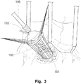
- sutures are spaced around the annulus (the point where the valve leaflet attaches to the heart) and then the sutures are attached to a prosthetic valve, see Fig. 3 .
- the valve is lowered into position and when the sutures are tied, the valve is fastened to the annulus. The surgeon may remove all or part of the valve leaflets before inserting the prosthetic valve.
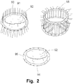
- Mitral and tricuspid valve repair is traditionally performed with a suture technique, e.g. by performing the so-called Parachute procedure, see Fig. 2 .
- Heart valve repair and heart valve replacement may be performed in combination, e.g. a dilated leaflet may be partially surgically removed (e.g. leaving the chordae intact) and a heart valve replacement prosthetic valve may be affixed to the surgically modified anatomical heart valve in order to restore heart valve function.
- annuloplasty ring is used to fixate an altered size of the annulus and/or support the annulus.
- the annuloplasty ring serves to keep the annulus in a reduced diameter and to allow the existing leaflets to oppose each other normally again, in order to restore correct valve function.
- Sutures are used to attach the prosthetic annuloplasty ring to the annulus of the heart valve and to assist in plicating the annulus.
- the annulosplasty ring Before permanently attaching the annulosplasty ring to the annulus, the latter is prepared to the desired shape by other means than the annulosplasty ring. This preparation of the valve in order to achieve a correct geometrical arrangement of the anatomical entities of a heart valve, and a restored correct function thereof, is hitherto performed manually by a surgeon. This part of the procedure is also called downsizing, which is explained in more detail below. Furthermore, manual downsizing may be dependent on a line of sight or suitable imaging modalities.
- the form of the valve leaflets may be corrected by surgical techniques, e.g. tiny sutures, during the same surgical procedure.
- the annuloplasty ring must be sutured to the valve annulus at the same time as a desired form of the latter is obtained at the end of the procedure.
- two highly integrated processes are involved in the Parachute procedure, namely a) downsizing, perhaps including reshaping, of a dilated valve and b) a subsequent fixation of an annuloplasty ring.
- the Parachute procedure is highly dependent on the experience of the performing surgeon, who has to be able to think sterically, as it is necessary to firstly place the sutures on the annulus and then through the support ring.
- a result of such a procedure may differ greatly and even provide a non-desired result, very much depending on the skills of the surgeon performing the procedure. If the ring is severely malpositioned, then the stitches must be removed and the ring repositioned relative to the valve annulus during restitching. In other cases, a less than optimum annuloplasty may be tolerated by the surgeon rather than lengthening the time of the surgery to restitch the ring.
- a device for repairing a heart valve comprises an implantation instrument.
- the implantation instrument comprises a first support ring, and a second support ring connected to the first support ring to form a coiled configuration.
- the first support ring is configured to abut one side of the valve and the second support ring is configured to abut an opposite side of the valve to thereby trap a portion of the valve tissue there between.
- the device further comprises an annuloplasty implant adapted to be attached to the heart valve annulus in order to reshape the annulus and allow the leaflets to open and close properly.
- the annuloplasty implant is connected to the implantation instrument for insertion to the annulus.
- the implantation instrument disclosed in WO2006/054930 provides already a major improvement of the previously known devices and methods.
- the devices and methods as disclosed in WO2006/054930 may further be improved as a primary reshaping for defining a working position of the insertion tool still has to be performed by the surgeon using a forceps instrument.
- Similar devices, suffering from analogous drawbacks are disclosed in e.g. US 2004/0167620 , US 2005/0149178 , and WO 2007/030063 .
- US2007/0038293 discloses methods, devices, and systems for performing endovascular repair of atrioventricular and other cardiac valves in the heart.
- Regurgitation of an atrioventricular valve can be repaired by modifying a tissue structure selected from the valve leaflets, the valve annulus, the valve chordae, and the papillary muscles. These structures may be modified by suturing, stapling, snaring, or shortening, using interventional tools which are introduced to a heart chamber.
- the tissue structures can be temporarily modified prior to permanent modification. For example, opposed valve leaflets may be temporarily grasped and held into position prior to permanent attachment.
- US2007/0038293 does only provide local modification of certain portions of a heart valve, e.g. by grasping one or more leaflets for bringing these into a position suitable for fixation of a clip to the leaflets. Hence, the motion of the valve leaflets is only partly and temporary immobilized.
- WO 2006/093656 devices and methods are disclosed for aiding valve annulosplasty.
- the disclosed devices comprise a radiopaque deformable reference ring facilitating imaging based navigation of an annulosplasty procedure.
- the devices are not providing an active downsizing. Downsizing still has to be performed in a separate manner.
- embodiments of the present invention preferably seek to mitigate, alleviate or eliminate one or more deficiencies, disadvantages or issues in the art, such as the above-identified, singly or in any combination by providing a medical device and a kit according to the appended independent patent claims.
- embodiments of the present invention provide for a separation (in time) of downsizing and reshaping.
- embodiments of the present invention provide for an advantageous downsizing, substantially simplifying the remainder of the valve repair or replacement procedure.
- Embodiments thus provide for both reducing complexity and time of previously known procedures.
- a medical device for repairing and/or replacing a heart valve comprised of valve tissue including an annulus and a plurality of leaflets for allowing and preventing blood flow through a patient's heart.
- the medical device is arranged for facilitating the repair and/or replacement of a defective heart valve of a heart and comprises a downsizing element devised to automatically provide downsizing of an annulus of the heart valve upon insertion of the downsizing element into the heart.
- the downsizing element is a distal helical loop shaped downsizing element devised to automatically provide downsizing of an annulus of the heart valve upon insertion of the downsizing element into the heart, wherein the downsizing element has a first shape to facilitate access to circumflex substantially all chordae of the heart valve, and a second shape to reposition the chordae towards a centre of the valve upon the insertion to provide the downsizing.
- the downsizing element has a first shape to facilitate access to circumflex substantially all chordae of the heart valve, and a second shape to reposition the chordae towards a centre of the valve upon the insertion to provide the downsizing.
- a kit for repairing a heart valve comprised of valve tissue including an annulus and a plurality of leaflets for allowing and preventing blood flow.
- the kit comprises a medical device for facilitating a repair and/or replacement of a defective heart valve of a heart of a patient according to the first aspect of the invention, wherein the device comprising a downsizing element devised to automatically provide downsizing of an annulus of the heart valve upon insertion of the downsizing element into the heart; and an annuloplasty implant adapted to be attached to the heart valve annulus in order to reshape the annulus and allow the leaflets to open and close properly, and/or a valve prosthesis adapted to be attached to the heart valve annulus or the annuloplasty implant in order to allow the heart valve to open and close properly.
- An exemplary method for repairing and/or replacing a heart valve comprised of valve tissue including an annulus and a plurality of leaflets for allowing and preventing blood flow.
- the method comprises inserting a medical device for automatically downsizing the annulus of the heart valve upon insertion of the medical device and prior to fixating an annuloplasty implant and/or valve prosthesis to the heart valve.
- the disclosure contemplates various examples of the medical device, including embodiments for catheter-based surgery and examples for open heart surgery.
- Another exemplary method is provided, comprising using the medical device according the first aspect of the invention in a medical procedure for repairing a heart valve comprised of valve tissue including an annulus and a plurality of leaflets for allowing and preventing blood flow through a patient's heart.
- Some examples provide for advantageous devices and/or methods for facilitating and/or providing treatment of regurgitation of mitral and tricuspid valves.
- the following description focuses on an embodiment of the present invention applicable to a repair of a defective heart valve and in particular to a reshaping the valve shape and/or area in order to facilitate insertion of an annuloplasty implant and/or artificial heart valve.
- the invention is not limited to this application but may be applied to many other heart valve disorders for which downsizing and/or reshaping of the valve shape and/or area is needed.
- a heavily dilated heart valve may be replaced with a heart valve prosthesis, wherein existing anatomical structures may be removed or partly removed.
- a part of the valve leaflets may be surgically removed, wherein it may be desired to keep as much of the leaflets as possible, e.g.
- An anatomically correct size of the heart valve prosthesis is preferably chosen for providing a restoration of valve function, which may necessitates downsizing, i.e. reshaping the dilated valve shape and/or area, prior to fixating the heart valve prosthesis. This downsizing is provideable by embodiments of the present invention.
- the methods and devices are applicable for both downsizing of mitral and tricuspid valves.
- a leaking valve e.g. mitral valve
- a supporting ring with a smaller diameter and/or area than the diameter and/or area of the leaking valve, and is fixated at a correct position by means of sutures (commonly by applying the tedious Parachute procedure illustrated in Figs. 2 and 3 ).
- the Parachute procedure sets demands on the performing surgeon, who has to be able to think sterically, as it is necessary to firstly place the sutures on the annulus and then through the support ring. The chance of failure is great.
- the downsizing of a dilated valve and the fixation of the support ring is a highly integrated process. An improvement provided by some examples of the present disclosure might be described as a separation (in time) of these two events; downsizing, and fixation.
- examples provide for reducing both complexity and time for the combined procedure.
- downsizing as used in the present specification is to be understood as an alteration of a heart valve, e.g. for a pre-annuloplasty, by means of
- a successful downsizing may be appraised by the leaflets of a heart valve having regained proper coaptation.
- some examples of the disclosure provide a restored proper coaptation of heart valve leaflets. This may be permanently fixated by annuloplasty implants subsequently fixated to the annulus of the heart valve.
- some examples of the disclosure provide a permanent downsizing and are left in place in the body.
- some examples of the disclosure may provide an improved, restored or proper leaflet coaptation that in addition is permanently supported by an artificial heart valve, in order to provide proper heart valve function.
- the aspect of downsizing may be performed in many ways. Some may be more suitable at specific circumstances although not applicable in others.
- some anatomical structures may be pushed, pulled or stretched to enforce a reshaping of an adjacent valve, i.e. the chordae, the leaflet or the annulus may be manipulated accordingly to achieve the desired downsizing of the heart valve.
- the heart valve may be permanently fixated in this shape and/or area by suitable elements, such as annuloplasty devices, or by leaving a downsizing element permanently in its position.
- Heart valve repair may include heart valve replacement.
- Heart valve repair may comprise installation of artificial heart valve prosthesis.
- a dilated heart valve leaflet may be partially surgically removed (e.g. leaving the chordae intact) and a heart valve replacement prosthetic valve may be affixed to the surgically modified anatomical heart valve in order to restore heart valve function.
- an artificial heart valve prosthesis may be attached to an annuloplasty device. Downsizing is thus alternatively or in addition to fixation of annuloplasty devices provided prior to fixation of artificial heart valves.
- Figs. 1a and 1b are given for illustrating the anatomical situation where examples of the disclosure are implementable.
- Fig. 1a is a schematic cross-sectional view of a heart 1 having a tricuspid valve 2 and tricuspid valve annulus 3.
- the mitral valve 4 is shown adjacent a mitral valve annulus 5.
- the mitral valve 4 is a bicuspid valve having an anterior cusp 7 and a posterior cusp 6.
- the anterior cusp 7 and the posterior cusp 6 are often referred to, respectively, as the anterior and posterior leaflets.
- Fig. 1a also shows the aorta 15, which is located adjacent the wall of the left atrium on the anterior side of the mitral valve. Also shown in the figure are the posterior commissure 17 and the anterior commissure 18.
- Fig. 1b is a cross sectional view of the left ventricle showing the mitral valve 4 in perspective.
- Fig. 1b illustrates a patient 10 having a heart 12 shown in cross section including a left ventricle 14.
- the concepts of the present invention are suitable to be applied, for example, to a mitral valve 18 which supplies blood into left ventricle 14.
- Mitral valve 18, as better shown in Fig. 1a includes an annulus 20 and a pair of leaflets 22, 24 which selectively allow and prevent blood flow into left ventricle 14.
- annulus tissue is used extensively throughout this disclosure in reference to the drawings, however, the inventive principles are equally applicable when referring to other valve tissue such as leaflet tissue or other attached vessel tissue.
- Leaflets 22, 24 are supported for coaptation by chordae tendinae or chords 26, 28 extending upwardly from respective papillary muscles 30, 32. Blood enters the left ventricle 14 through the mitral valve 4 and is expelled during subsequent contraction of the heart 12 through the aortic valve 34. It will be appreciated that the present invention is applicable to tricuspidal heart valves as well.
- a medical devices collects the chordae, or bundles of chordae, for providing a downsizing of the corresponding adjoining heart valve. Some examples collect at least substantially all the entire chordae in a single working operation.
- the medical devices comprise a downsizing element devised to automatically provide downsizing of an annulus of the heart valve upon insertion of the downsizing element into the heart. Insertion may be performed from the atrial side or the ventricular side of the valve.
- the downsizing element is arranged to automatically reposition the chordae 26, 28, e.g. towards a centre of the valve, upon the insertion to provide the automatic downsizing.
- the medical device facilitates a repair and/or replacement of a defective heart valve of the heart of a patient.
- chordae manipulating downsizing elements will now be described.
- medical devices are provided that are arranged and comprise one downsizing element to physically circumflex around substantially the entire chordae tendinae of a valve, gripping the latter in a gentle manner such that a distinct temporary downsizing of the valve is automatically provided by inserting the medical device accordingly.
- the downsizing element has a first shape to facilitate access to circumflex substantially all chordae 26, 28 of the heart valve, and a second shape to reposition the chordae 26, 28 towards a centre of the valve upon the insertion to provide the downsizing.
- the downsizing element comprises a distal helical loop shaped element configured to be positioned on a first side of an area of valve tissue oriented towards a cardiac chamber of the heart comprising a plurality of chordae.
- the distal loop shaped element is arranged to at least temporary circumflex substantially all the chordae 26, 28 and to rearrange a position of the chordae 26, 28 upon the insertion thereof to provide the downsizing.
- the distal loop shaped element is brought into apposition with the chordae and then draws together the chordae in a suitable manner. This may be provided by reducing the interior area or shape, e.g. the diameter, of the distal loop shaped element in relation to the anatomical diameter of the chordae. Reducing the area or shape may be provided actively, e.g. by shape memory materials, tendons etc., as described below. Alternatively, or in addition, the reduction area or shape may be provided in a more passive way, e.g. by rotating a first loop shaped element, having a decreasing inner area or shape in axial direction thereof, axially along the chordae.
- the valves are blocking the view of the chordae tendinae, as shown in Fig. 1a .
- the anatomy of the valve makes it possible to go beneath a valve, e.g. through a commissure thereof or by penetrating the annulus thereof, and thereby reaching an anatomical space near the valve between the wall of the heart and the chordae tendinae.
- the chordae may be collected within a helical device comprising the distal loop shaped element, whereby the chordae may be drawn together for downsizing the valve, upon insertion of the device. Downsizing is thus provided by making use of the helix-shaped device.
- the helical device has a helical structure that is arranged on an imaginary cylinder and where a defined distance is kept between subsequent turns of the helix, i.e. a hollow centre and a free space is provided between each turn.
- the helix may have a blunt tip in order to not harm the anatomical structure of the heart.
- the tip of the device may be arranged with a larger diameter than the subsequent part of the helix that circumflexes the chordae.
- the device may be inserted through either commissure at a valve or penetrating through the valve annulus, whereby the chordae tendinae will be circumflexed by the helical structure as the device is inserted continuously.
- the diameter of the helical structure i.e. diameter of the imaginary cylinder, is defined prior to insertion and set smaller than corresponding value of the valve, hence the valve will be downsized as the helix is inserted and circumflexing all of the chordae tendinae.
- the helical device comprises the distal helical loop shaped element, which thus is "loop-shaped" with an open distal end.
- the loop shape is provided as a curved shape that is continuous towards a proximal part of the device, e.g. with a circular, elliptic, or D-shaped form or any other curvature which may provide a suitable downsizing of the shape of the valve annulus.
- the term "loop-shaped” also includes a curved shape that is open forming an arcuate shape, such as a C-shape or U-shape.
- the term "loop-shaped” also includes a curved shape overlapping itself to form a portion of a coil.
- loop-shaped also includes three dimensional curves as mentioned in the previous paragraph.
- the number of loops of the helix may be different and vary from e.g. a half turn (e.g. C-shape or U-shape) up to several turns.
- the cross section of the helix may differ along the longitudinal extension of the helix in some examples.
- Some examples may be provided for catheter-based surgery, for transvascularly introducing into position. Some examples may be provided for open heart surgery, e.g. in a rigid configuration.
- a catheter and/or wire may be fed generally axially into place around the entire, or at least substantially the entire chordae (either through the leaflets from the atrial chamber or from the ventricular side of the valve).
- a wire is fed into the central lumen to form the catheter to the desired curvature around the chordae, gather the chordae, and alter the curvature of the valve annulus, generally to a smaller diameter or radius through at least a segment of the annulus circumference.
- the wire may for instance be pre-shaped, spring formed, memory biased, tension wound or braided, plastic polymer formed, in order to achieve the desired curvature.
- a wire of pre-formed shape may also be provided and used to change the shape of the catheter upon axial rotation of the wire after it has been fed into the catheter.
- the catheter may also be altered in shape or curvature as a result of fluid (gas or liquid) pressure or vacuum exerted on the inner lumen of the catheter, as in the case of a balloon catheter.
- the catheter may be provided as shape biased to curve under pressure applied to the central lumen or when pressure or vacuum is applied to one of a plurality of lumen, creating a high pressure distended lumen and/or a low pressure contracted lumen, as desired, in order to circumflex, grab and modify an anatomical structure, such as the entire chordae of a heart valve.
- a sleeve or catheter of a desired curvature may be fed over the wire and around the chordae to gather the chordae and alter the curvature of the valve annulus, generally to a smaller diameter or radius through at least a segment of the annulus circumference.
- the catheter may for instance be pre-shaped, spring formed, memory biased, tension wound or braided, plastic polymer formed, in order to achieve the desired curvature.
- a sleeve or catheter of pre-formed shape may also be used to change the shape of the catheter upon axial rotation of the sleeve or catheter after it has been pushed over the wire.
- actively steerable wires or catheters may be provided and used to modify an anatomical cardiac structure for achieving a downsizing. For instance, in case the annulus does not have a smooth path, abrupt change in direction or is extensively elongated or presents some other irregularity, a steerable device may be provided. As the path may be blocked, while inserting the device through a commissure, small adjustments of e.g. the direction of the tip of the device may steer and overcome the obstacle. Insertion of a helical device via either commissure and rotating the device, e.g. a full loop, i.e.
- a 360 degree turn, parts thereof, or multiples thereof, introduces the device in the interspace between the heart muscle wall and the chordae tendinae.
- the entire, or at least substantially the entire chordae tendinae are circumflexed by the device, as e.g. illustrated on the right in Fig. 17 showing a medical device 50 circumflexing the chordae and downsizing a heart valve annulus.
- the actual retraction of the chordae tendinae towards the centre of the annulus may be already be achieved by the shape of the medical device.
- the retraction of the chordae may be provided by an electroactive system implemented within the device.
- Intrinsic parts of the device may be activated by electric energy.
- the total length of the device may be shortened in this manner, and hence its circumference gets smaller, resulting in a downsizing of the annulus.
- the device may be configured to be elongated on its outer while it is shortened on the inside or only one of these configurations. The effect is that the device will get a curvature, bending in the direction of the device gets shorter.
- Tendons or tension elements may be used in an inner lumen of a catheter structure to generate a compressive force on one side of a catheter wall in order to provide a controllable curvature of the catheter.
- Tension in the tendon is for instance generated by a screw or pully mechanism, remotely operated e.g. in the catheter handle.
- the curvature of the distal catheter tip is determined by the form of the catheter wall itself, e.g. its wall thickness, notches or features to allow flexibility in the catheter.
- a dual profile steerable catheter is disclosed, which is used for treating e.g. cardiac arrhythmia.
- the catheter has tendons housed within a sheath such that a movement of tendons in proximal direction causes a distal end region of the sheath to deflect.
- a steerable catheter may be fed generally axially into place around the chordae, either through the leaflets from the atrial chamber or from the ventricular side of the valve, and the shape of the catheter may be altered, e.g. using tendons, to form the catheter to the desired curvature around the chordae, gather the chordae, and thus alter the curvature of the valve annulus, generally to a smaller diameter or radius through at least a segment of the annulus circumference.
- elements may be provided and used to create a pushing force, instead of a pull, in a catheter lumen to deflect the catheter or a downsizing element of the medical device.
- Electroactive polymers i.e. micromuscles
- the shape of the medical downsizing device may be actively controlled, e.g. by electroactive polymers.
- Electroactive polymers are known to increase or decrease in bulk volume, which may be used to create expansion or contraction forces on one side or another of a catheter lumen.
- an universal, programmable guide catheter for coronary treatment which comprises electroactive polymer actuators to change shape of the catheter based on control signals received from a control unit.
- electroactive polymer based artificial sphincters and artificial muscle patches are disclosed for treating, e.g. fecal incontinence, which has a cuff for placement around a body lumen and electroactive polymer actuator.
- a control unit is provided for controlling the actuators to expand or contract the cuff.
- the artificial muscle patches which are adapted to be implanted adjacent a patient's heart, and the artificial sphincter cuffs are adapted to be implanted around a body lumen, such as the urethra, the anal canal, or the lower esophagus.
- a construction comprising electroactive polymer actuators may for instance be provided at a catheter tip or distal portion of a partly flexible helical downsizing device, allowing for gathering anatomical structures like the chordae and downsizing of a heart valve annulus.
- Rotating elements may be used for changing the curvature of downsizing elements.
- the above mentioned wire may comprise sections of elements rotatable relative each other with an inclination angle, thus leading to a curvature of the wire controllable by rotating the latter, e.g. in relation to a distal end of the wire fixed to a catheter sheath.
- the downsizing element may be introduced through a commissure and be guided in between the wall of the heart and the chordae tendinae. As a full 360 degree rotation is completed the outer most end of the inserted device returns to the commissure and site of entrance.
- the thread tip may be pulled as a lasso structure, whereby gently applying a pulling force to the ends of the thread will downsize the valve in respect to the amount of force applied.
- the alteration of a valve may be provided by pulling the outer rim of the leaflet by means of a forceps device.
- the reduction in size of the valve depends on the applied force, on each leaflet, and on the overall rigidity of the anatomic structures of the heart surrounding the specific valve in question.
- the valve may be altered to a larger extent in the transversal than in the longitudinal direction by the method; however it will depend on how the applied force is distributed across the annulus. For instance, using at least one forceps for each leaflet to grab gently the edge of each leaflet and pulling the edges towards each other, the size of the valve may be altered. This downsizing using forceps may be performed automatically, e.g. robot based and/or ultrasound feedback controlled.
- Another approach is to apply an adjustable tape pulling the annulus.
- an adhesive surface a strip may be attached to the leaflets, thus securing a firm grip, whereby the leaflets may be pulled toward each other.
- the adhesive must be designed for biological tissue to have a desired effect of firmly attach to the leaflet.
- This downsizing using adjustable tapes may be performed automatically, e.g. robot based and/or ultrasound feedback controlled.
- Another method may comprise attaching arms to the annulus, i.e. distal the leaflet edge, and applying a pulling force with these arms.
- the arms may have barbs or an adhesive surface at the outer end securing a firm grip at the annulus. The effect is dependent on how firmly the arms are anchored at the annulus and the numbers of arms, the amount of force applied and the overall rigidity of the heart surrounding the annulus. This downsizing using arms may be performed automatically, e.g. robot based and/or ultrasound feedback controlled.
- An "Alfieri" type repair for mitral insufficiency may be performed by suturing the free edges of the leaflets together thus generating a double orifice appearance.
- the procedure is performed by open heart surgery and may be suitable in downsizing a valve temporarily.
- Mitraclip Evalve Inc., Redwood City, CA, US.
- the device a fabric covered clip capturing both free edges of the leaflets, is delivered by a transseptal catheter creating a double orifice.
- the valve annulus has hitherto not been modified or downsized when using the Mitraclip devices.
- the Mitraclip devices did hitherto not allow for an automatic pre-annuloplasty change of shape of the annulus for facilitating the annuloplasty procedure.
- Mobius device Edwards Lifesciences, Irvine, CA, US
- Mobius device captures the free leaflets via a transatrial guide catheter.
- the process uses a vacuum port to secure the leaflet and a needle places a suture.
- the process is then repeated for the adjacent leaflet. As both leaflets are captured they are drawn together and a small clip securing the suture finishes the procedure.
- the Mobius device has hitherto not been used for downsizing.
- Encircling collars may be provided for downsizing purposes, e.g. in form of lassos, clamps or cuff collars, as explained below.
- a lasso may be placed around the valve chordae, either through the leaflets from the atrial chamber or from the ventricular side of the valve.
- the chordae may then be gathered, and the curvature of the valve annulus altered, generally to a smaller diameter or radius through at least a segment of the annulus circumference, i.e. a downsizing is achieved.
- An automatic downsizing to a desired degree of downsizing may be achieved by providing a suitable end position or stop of the lasso.
- US 6,123,703 an ablation catheter and methods for treating tissues are disclosed.
- a deployable closed loop is shown.
- US 6,123,703 deals with an ablation catheter system for treating tissues or atherosclerotic tissues of a patient.
- the catheter system has a retractable metallic element means comprising the deployable close loop with a running noose at its end, and the ablation catheter provides RF therapy to the tissues through the retractable metallic elements means.
- a clamping device may be positioned around the external features of the heart, e.g. around the atrial-ventricular (AV) groove or on the left ventricular free wall to push in the valve annulus anatomy and bring the annulus into the desired shape for placement or a prosthetic device.
- the clamp may be in the form of at least one and perhaps two opposed clamping surfaces.
- the clamp may have a shape to match the desired heart anatomy.
- the clamp may be drawn together like a screw clamp or forced together in a tong like device.
- An automatic downsizing to a desired degree of downsizing may be achieved by providing a suitable end position or stop of the clamp(s).
- a clamping collar may be positioned around the external features of the heart, probably around the AV groove or on the left ventricular free wall to push in the valve annulus anatomy and bring the annulus into the desired downsized shape for placement of a prosthetic device.
- the collar may be in the form of at least one, such as two opposed, encircling band elements.
- the collar may be of a shape to match the desired heart anatomy.
- the collar may be drawn together like a lasso, or be forced together in a tong like device or screw clamp device.
- the cuff may be similar cuffs developed by Acorn Cardiovascular and Paracor to restrain the heart from further dilation, namely the HeartNetTM Device.
- the cuff device may be used to form the heart into the desired shape to shape the valve annulus appropriately for prosthetic device placement or another form of repair.
- An automatic downsizing to a desired degree of downsizing may be achieved by providing a suitable end position or stop of the cuff or collar.
- the mitral valve From the surface of the heart muscle force may be applied, reshaping the anatomic configuration of the myocardium.
- the mitral valve it is possible to use the adjacent sinus coronaries as an access path, which is reachable via a minimal invasive method.
- WO02/062270 Long-term therapeutic devices using this access path for treating mitral insufficiency are e.g. disclosed in WO02/062270 of Solem and Kimblad.
- a device is disclosed in WO02/062270 for treatment of mitral annulus dilatation that comprises an elongate body having two states. In a first of these states the elongate body is insertable into the coronary sinus and has a shape adapting to the shape of coronary sinus. When permanently positioned in the coronary sinus, the elongate body is transferred to the second state assuming a reduced radius of curvature, whereby the radius of curvature of the coronary sinus and the radius of curvature as well as the circumference of the mitral annulus is reduced.
- the elongate body comprises a distal stent section, a proximal stent section and control wires between the two stent sections for reducing the distance between the distal and proximal stent sections for achieving the change of curvature.
- Various shape effecting devices may be placed temporary in the sinus coronaries for a temporary downsizing effect facilitating an annuloplasty procedure. After terminating the procedure, the devices are then removed from the coronary sinus.
- Tendons may be used for changing the shape of a medical device, such as shown in Fig. 10 .
- the downsizing element comprises a plurality of segments 312 moveable in relation to each other, and a tendon 314 inserted along the plurality of segments 312, wherein the tendon is distally attached to a distal end portion of the downsizing element, such that the downsizing element decreases radially at least along a portion thereof upon pulling at a proximal portion of the tendon 314.
- Electroactive elements e.g. micro muscle
- Electro active elements e.g. polymeric elements as described above may be provided in elongate elements insertable into the sinus coronaries.
- Rotating elements may be used for changing the curvature of downsizing elements insertable into the coronary sinus.
- a temporary fixation element for facilitating the desired change of shape of the downsizing elements.
- an inflatable balloon may be provided at a distal end of the device. Upon inflating the balloon, a fixation point is provided and the flexion of the temporary downsizing element is facilitated. When the annuloplasty procedure is finalized, the balloon is deflated again and the downsizing element is removed from the coronary sinus.
- the circumflex artery may be used as an access path for temporary downsizing elements, devices or assemblies adapted for downsizing of an adjacent heart valve.
- the myocardium (heart muscle) may be exposed to a stimulating element or agent resulting in a local contraction thereof providing a temporary downsizing. This may be provided both minimally invasive or during open chest cardiac surgery.
- the stimulation may be provided by electrical charges delivered locally to the myocardium, e.g. by means of an electrode.
- the electrode may be positioned in a catheter based minimally invasive manner.
- Locally cooling down the cardiac tissue may be used to provide downsizing a valve annulus temporarily.
- Various chemical substances or pharmacological agents may affect the contraction of the myocardium and provide downsizing of a valve annulus.
- the substances or agents may be delivered to the desired cardiac target site by a syringe needle or a hollow catheter e.g. having a hollow steerable needle tip, e.g. a smart needle.
- a further stimulus providing a temporary downsizing is radiation, e.g. from a radio frequency source.
- Chordae tendinae are approximately 80% collagen, while the remaining 20% is made up of elastin and endothelial cells.
- a part of the collagen may be temporary removed from the chordae for the downsizing. Collagen is rebuild after a certain time and restores function of the chordae.
- the compression delivers a force uniformly over the area whereon the cuff is placed. With correct placement the shape of the annulus is affected, and downsizing of the same may be achieved.
- the myocardium may be elongated, with the use of an external force, whereby the circumference of the myocardium at a cross-sectional plane close to the mitral valve and tricuspidal valve is reduced. Hence, these valves will be reshaped, and a downsizing may be achieved.
- the force may be of a mechanical origin, as applying a pulling force at the apex cordis while fixating the superior part of the myocardium.
- the fixation of the pulling device at the apical area of the heart must be firm as well as gently in order not to harm the tissue.
- the force for fixation of the apical area may be provided utilizing a suction cup.
- a suction cup By providing a vacuum, a secure fixation may be reached. Still a fixation of the superior part of the myocardium must be firm. While applying a pulling force at the apex cordis the rim of the suction cup together with the smoothness of the heart surface set boundaries to the amount of force the transition zone can bridge.
- the heart muscle may be mechanically fixated by one or several pins though the whole extension of the heart, as well as the chordae. As the heart is fixated it may be compressed by applying force at each pin end, in a direction towards the centre of the heart. With suitable position of these pins a valve and corresponding annulus may be affected by the applied force, whereupon the valve is reshaped, and a downsizing may be achieved.
- the compression may be suitable to temporary compress an atrium to reshape the superior dimensions of the heart.
- the compression may provide a force uniformly over the area whereon e.g. a cuff is placed. With correct placement the shape of the annulus is affected, and downsizing of the latter is achieved.
- ribbons or flexible bands may be positioned near or on top of the sinus coronaries to restrain the mitral valve. As the ribbon is tightened a compression force is applied to the mitral valve which may reduce its size.
- the method is however more rough than corresponding compression utilizing a cuff arrangement mainly because of two reasons: ribbons are most often small in width which may damage the tissue as the ribbons get tightened and the heart tissue may be callipered at the junction as well.
- aortic wall as a backbone, support, for a balloon
- displacement of the aorta septal wall may be possible.
- the balloon will upon inflation, either by fluid as saline or other non-harming fluid or gas, induce a force towards the heart thereby causing a displacement of the heart structure.
- the amount of displacement is dependent on the overall rigidity of both the heart muscle and the aortic wall.
- rupture or weakening the aorta must be avoided.
- one or more papillary muscles may be circumflexed.
- a lasso may be positioned around a single papillary muscle, or several papillary muscles, or all papillary muscles. Pulling the ends of the lasso arrangement and drawing towards the cardiac apex, i.e. away from the heart valve, may provide downsizing thereof.
- Helical devices may be provided and used for this purpose. An access way for such a device and method is via the apex through the myocardium. Transapical access is described below in more detail.
- the parachute technique may be simplified by examples of the present disclosure.
- the downsizing of an annulus may be provided prior to placing the sutures carrying an annuloplasty prosthesis. In this manner, the surgeon does not need to take into consideration a further change of shape of the annulus imposed by the position of the sutures.
- the alignment of the annuloplasty prosthesis is thus facilitated and the parachute procedure substantially simplified.
- the helical device is provided and used for this purpose.
- both ends of a single suture are sutured through the natural annulus, taking a relatively large gap between the needle penetration points.
- the two ends of this same suture are then passed through the prosthesis.
- the prosthesis is held away from the natural valve annulus during this procedure to allow easy access to the downsized annulus and the prosthesis.
- the prosthesis is easily aligned to the downsized annulus during this procedure, as the downsized annulus has a shape or contour adapted to that of the annuloplasty prosthesis.
- the suturing pattern is repeated using additional sutures, resulting in several suture "pairs" spaced around the downsized annulus.
- the prosthesis is then lowered or parachuted down against the downsized annulus. After all the suture pairs are secured, the result is a reduced annular circumference with an attached prosthesis.
- the downsizing medical device providing the downsizing may then be removed as the prosthesis now fixates the downsized shape permanently.
- Percutaneous methods and techniques that may be applicable in downsizing a heart valve may be used. Even at open surgery it may be feasible to address the heart by some catheter based therapy. Access routes for the downsizing devices comprise the following routes, including catheter based therapy:
- a path to reach the mitral valve is by applying a transaortic approach entering the myocardium on the arterial side, reaching the mitral valve from beneath, the valve is up-stream.
- the specific method is chosen to downsize the valve may be some of the above mentioned.
- Another path to reach the mitral valve is by a trans septal approach, entering the myocardium on the venous side at the vena cava.
- the mitral valve is reached from beneath.
- the specific method chosen to downsize the valve may be some of the above mentioned.
- the heart From the venous side the heart is reached via vena cava and entering the left atrium.
- the tricuspid valve is reached from above, trough the leaflets.
- the specific method chosen to downsize the valve may be some of the above mentioned.
- WO2005/104957 it is disclosed how the mitral valve and the tricuspid valve can be reached from beneath by entering at the apical area of the myocardium, hence the valves are reached from below. It is suggested to enter percutaneously at the thorax at the fifth intercostal space, at the left side of the chest, other suitable entrance position are suggested as well.
- the suggested approach to reach the heart valves give possibilities to use larger surgical equipment than usually at percutaneous procedures.
- the lumen of the vessels normally sets an upper boundary on the equipment size.
- the suggested approach of entrance is directly trough the apical area of the heart, restrains are set by this anatomical structure.
- the specific method chosen to downsize the valve may be some of ones mentioned herein. A further detailed example of this access path is given below.
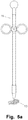
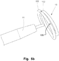
- Fig. 5a is a lateral view of a medical device 10 according to an example of the disclosure, attached to a delivery handle 11.
- Fig. 5b is a perspective view of the medical device 10 of Fig. 5a in an enlarged view.
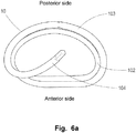
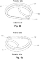
- Figs. 6a , 6b and 6c are detailed illustrations of the medical device according to Fig. 5b without the delivery handle.
- the medical device 10 is a pre annuloplasty downsizing device of the kind that is above referred to as helical or loop shaped device.
- the medical device 10 is a tool adapted to downsize a heart valve annulus for facilitating an annuloplasty procedure.
- the medical device 10 comprises a first and a second loop shaped, helical element 102, 103 assuming a helical structure on an imaginary cone and where a defined distance is kept between subsequent turns of the helix, i.e. a hollow centre and a free space between each turn.
- the medical device comprises further a proximal end 104 for releasably attaching a handle 20, and a distal end 101 in insertion direction of the medical device 10.
- the handle may be disengaged from the medical device 10.
- the cone shaped coil may resemble a spiral, helix like or keyring-type configuration.
- the second loop shaped element is connected to the first loop shaped element to form a coiled configuration, wherein the second loop shaped element is configured to be positioned on a second, opposite side oriented towards an atrium of the area of the valve tissue to thereby arrange the valve tissue between the first loop shaped element and the second loop shaped element, and wherein the second loop shaped element comprises at least one fixation element for releasable attachment of an annuloplasty implant or a heart valve prosthesis.
- the first and a second loop shaped, helical elements 102, 103 may also be referred to as rings, laps or turns.
- the first ring is to be positioned within a cardiac chamber adjacent to, or in the vicinity of the valve tissue.
- the second ring which at least partly may have a slightly larger circumference than the first ring, is to be positioned in the atrial side of the valve, i.e. adjacent to, or in the vicinity of the annulus of the valve.
- the distal end 101 of the helical medical device 10 is introduced at a commissure of the valve and rotated further for reaching its final position of use with the two helical elements 102, 103 on either side of the heart valve.
- the medical device may also penetrate the annulus of the heart valve instead of passing through the commissure.
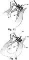
- the positioning and downsizing procedure making use of the medical device 10 is explained in more detail below with reference to Figs. 12 and 13 .
- the medical device 10 may comprise elements facilitating temporary fixation of other devices to the medical device 10.
- through-holes 105 in the loop shaped elements, or selected portions thereof may provide temporary fixation of other elements, such as an annuloplasty implant, and/or a heart valve prosthesis to the medical device 10, e.g. by means of sutures.
- other fixation means may be used for this purpose, such as clips, releasable staples, bands, etc.
- the other element itself may be devised for the temporary fixation, e.g. by having a spring function temporary grabbing around one of the loop shaped elements.
- the other element may thus be removed from the medical device 10 to the site of implantation, e.g. by removing the fixation means, such as sutures, clips, etc. or by turning over, stretching, expanding, etc. the other element from the medical device 10 for fixation to the anatomical structure at the implantation site.
- the distal end 101 is shaped in such a manner, that it catches the chordae (26, 28 for the mitral valve) by advancing between the chordae and the opposite cardiac muscle tissue 12.
- the distal end 101 is arranged for catching the chordae inside the first helical element 102.
- the distal end 101 may for this catching purpose be directed radially outwards or axially downwards from a diametric plane of the second helical element 103.
- the tip of the distal end 101 may be blunt, e.g. rounded, or provided with a spherical element. This provides for advantageous catching the chordae without risking injury or damaging the chordae or ventricular tissue.
- the device is provided with a connection interface for releasably attaching a delivery device, such as handle 11, such that a handling, direction and rotation is provideable to the medical device 10 in use thereof.
- a delivery device such as handle 11
- the delivery handle may be integral with the medical device 10.
- the proximal end 104 is arranged substantially perpendicular to a plane diametric to the loops of the medical device 10.
- the proximal end 104 may be arranged along a longitudinal axis imaginary arranged perpendicular to the plane diametric to the loops and in a center of the loops.
- the proximal end may also be arranged off-center, depending on the patient specific anatomical situation.
- the body of the present example of the medical device 10 extends along the first helical element 102 with a reduced radial extension.
- the entire chordae of a heart valve are circumferentially gripped and upon rotation gradually moved towards the center of the medical device 10, defined by a longitudinal axis thereof.
- the movement of the chordae for the downsizing is dependent on the rotational direction of the medical device 10 in relation to the longitudinal axis of the medical device 10.
- the effective turns (as e.g. shown in Fig. 12 and 13 ) needed for providing a desired downsizing may be variable, including parts of turns, depending on the shape characteristics of the helical elements, e.g. their pitch, amount of taper of the helical windings, etc.
- the examples of the medical device may be rotated in full turns, quarter turns, half turns, multiple turns etc.
- a non-circular shape of at least a part of the helical windings may be used for providing a desired variable downsizing effect, depending on the degree of rotation when introducing the medical device 10.
- a D-shaped medical device 10 as illustrated in Figs.
- 6a to 6c may advantageously provide downsizing in a preferred direction, e.g. between the anterior side and the posterior side of the heart valve, e.g. for changing the shape of the mitral valve annulus in such a manner that two valve leaflets of the mitral valve are pushed towards each other without compressing the valve leaflets in the longitudinal direction thereof.
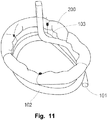
- an annuloplasty ring 200 may be temporary attached to the second helical element 103 and thus conveniently arranged for fixation to the valve annulus. Fixation of an annulosplasty ring to a valve annulus is e.g. described in WO2006/054930 . Holes may be provided in the second helical element 103 for providing temporary fixation points for the annuloplasty ring 200 to the medical device 10. For instance in Fig. 11 , the fixation is illustrated with sutures that are removed upon downsizing of the valve annulus by means of the first helical element 102 and positioning of the annuloplasty prosthesis 200 at the annulus.
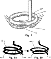
- Fig. 7 is a schematic view of the medical device of Figs. 6a-6c with an annuloplasty prosthesis attached thereto, in use at a heart valve tissue.
- the distal end 101 of the medical device is introduced through the commissure and is rotated to position, passing in between the heart muscle wall and the chordae. As the diameter is decreasing the chordae are pulled inward to the centre of the medical device and thus of the valve.
- the valve annulus has been downsized to a desired degree allowing fixation of the shape and area thereof, e.g. by means of the annuloplasty prosthesis 200.
- the annuloplasty prosthesis 200 is removed from the medical downsizing device 10 and fixated to the valve annulus, the medical device 10 is counter rotated and then withdrawn from the patient.
- a downsizing of the valve is automatically achieved in one step and the desired shape and area of the valve is provided for long-term fixation, e.g. by an annuloplasty ring.
- the downsizing may also be achieved in a long-term perspective for therapeutic purposes, thus further facilitating and simplifying the repair of valve regurgitation.
- the medical downsizing devices are left in place at the termination of the medical valve repair procedure. This may be provided by disengaging a delivery unit, such as a handle or a catheter wire, from the downsizing element.
- any suitable medical grade material(s), such as medical grade metals or plastics, may be used to form the medical device 10.
- the medical device 10 may have a traditional cross sectional shape associated with a keyring.
- flat, opposed surfaces are arranged to be positioned on either side of a valve annulus tissue 20, the first ring in the cardiac chamber and the second ring in the atrium.
- the opposed surfaces 45 may also be roughened in order to improve engagement with the valve annulus 20.
- Viewed cross sectional, perpendicular to the longitudinal axis of the helical structure the various examples of the disclosure may have a variety of geometric appearances e.g. circular, oval.
- Some examples may comprise changes of the cross sectional geometric form along the length of the medical device, e.g. the first and/or second ring may have different geometric shapes and varying cross sections, at least at portions thereof.
- the annuloplasty implant 200 may be attached to the second helical element 103 of the medical device 10, by means of sutures or clips.
- the annuloplasty implant 200 may be any type of annuloplasty ring or band or C-formed band, such as the CG FutureTM Annuloplasty System manufactured by Medtronic, Inc., the SJM Tailor® Annuloplasty Ring or the SJM Tailor® Flexible Annuloplasty Band manufactured by St. Jude Medical, Inc., the SoveringTM manufactured by Sorin Group, the Carpentier-McCarthy-Adams IMR ETlogix Annuloplasty Ring® or the Carpentier-Edwards Classic Annuloplasty Ring® manufactured by Edwards Lifesciences Corporation, which annuloplasty ring may form a complete ring-shape or an arcuate shape.
- the annuloplasty implant 200 is adapted to be attached to the valve annulus 20 by means of suture threads.
- the annuloplasty implant 200 has a shape conforming to a desired shape of the valve annulus 20. Thus, when attached to the valve annulus 20, the annuloplasty implant 200 will keep the, by downsizing reshaped, valve annulus 20 in the desired shape.
- the annuloplasty implant 200 is non- stretchable lengthwise, which implies that when attached to the valve annulus it will not allow dilatation of the annulus.
- the annuloplasty implant may be flexible to change its shape while maintaining its length to allow the normal movements of the valve annulus 20 during a heart cycle.
- the annuloplasty implant 200 may have sections of differing rigidity and flexibility to comply with the normal movements of the valve annulus 20 during the heart cycle.
- Figs 7-8a and 8b a method for repairing a heart valve by means of examples of the medical device will now be described.
- access to the heart valve is achieved by conventional techniques, including arresting the heart and opening the chest.
- Fig. 7 the device is shown when being inserted to the mitral valve 18.
- the distal end 101 of the first helical element 102 is brought to a corner of the opening between the leaflets 22, 24 of the mitral valve 18.
- the end 101 is led through the opening and the coil-shaped medical device 10 is turned, e.g. 360 degrees.
- the first helical element 102 is rotated into place on one side of the valve 18, whereas the second helical element 103 is placed on the opposite side of the valve 18.
- the medical device 10 is arranged in engagement with the valve 18, as shown in Fig. 7 .
- the medical device is rotated into position and. Thereafter, the first helical element may be drawn towards the center of the medical device, drawing together the chordae, as shown in Fig. 8b .
- the movement of the first helical element 102 towards the center of the device 10 may be implemented in various ways. In some examples a shape memory effect may be taken advantage of.
- a tether line 314 may be used for drawing together a flexible first helical element 102, as shown in Fig 10 .
- the first helical element 102 may comprise a plurality of interconnected segments 312 allowing a change of shape of the first helical element 102, as shown in Fig 10 .
- a single partial loop shaped element 310 is provided. Other examples may comprise several such loop shaped elements or only a portion thereof.
- the medical device comprises of three rigid supporting elements, i.e. one added supporting element. Based on the helical structure the entire lowest ring has a diameter suited to be introduced in between the heart muscle wall and the most inner chordae tendinae for a heart with a dilated valve. The next lap has a smaller diameter in order to reduce the valve diameter.
- a conventional annuloplasty ring 200 may be connected at the topmost lap of the device for delivery to the annulus.
- the medical device 10 may comprise a third helical element for providing a function of support rings, as described in WO2006/054930 with reference to Fig. 8 thereof.
- the leaflets 22, 24 need in the present examples not be drawn towards each other through a pinch of the support rings by means of a forceps instrument.
- the leaflets are already brought in a desired shape by the downsizing procedure. However, further adjustments may be made manually in this example, if so desired.
- the support rings may be arranged to flex away from each other to allow drawing the leaflets 22, 24 through the pinch and to flex towards each other for preventing the leaflets 22, 24 to slip back.
- the valve annulus 20 may in this way be temporarily held in the new shape by means of the medical device 10 comprising two support rings configured to be arranged on opposite sides of the valve annulus and arranged to provide a releasable pinch between each other.
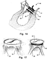
- Fig. 14 is a schematic illustration showing the medical device of the invention inserted, circumflexing the chordae and providing a pre-annuloplasty downsizing of the mitral valve.
- a first support ring 41 and a second support ring 43 are configured to be arranged on opposite sides of the valve annulus.
- the second support ring 43 provides the downsizing by circumflexing the chordae.
- a distal helical loop shaped element 42 provides for an advantageous insertion and circumflexing of the chordae, as well as variable downsizing, as explained above.
- the support rings may have roughened, opposed surfaces to better keep the leaflets 22, 24 from slipping through the pinch and to hold the valve annulus 20 in its reshaped form.
- the annuloplasty implant 200 which has been carried into position by means of the second helical element, may now be attached to the valve annulus 20 for achieving a permanent reshaping of the annulus 20. Since a primary reshaping has already been made by the downsizing procedure, the positioning of the annuloplasty implant 200 is facilitated.
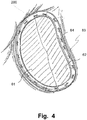
- the annuloplasty implant 200 is then sutured to the valve annulus, as illustrated in Fig. 4 , showing a completed suture 60 attaching the annuloplasty implant 200 to the valve annulus 20 and showing a suture being performed.
- the annuloplasty implant 200 is firmly attached to the valve annulus 20 for keeping the valve annulus 20 in its reshaped form.
- the annuloplasty implant 200 When the annuloplasty implant 200 has been firmly attached to the valve annulus 20, the annuloplasty implant 200 is released from the medical device 10. The sutures holding the annuloplasty implant 200 attached to the second helical element 103 are cut in order to release the annuloplasty implant 200 from the medical device 10. Now, the medical device 10 may be withdrawn. The medical device 10 is turned 360 degrees in order to rotate the first helical element 102 to be retracted through the opening between the leaflets 22, 24. Thereafter, the medical device 10 may be retracted from the patient, e.g. by means of handle 20. As shown in Fig. 4 , the annuloplasty implant 200 is now left in the patient holding the valve annulus 20 in a reshaped form such as to function normally.
- the distal helical loop shaped element of the medical device is at least partly made of a shape memory material, such as a shape memory alloy or a shape memory polymer (SMP) configuration, wherein the SMP in some examples may be radio-opaque.
- a shape memory material such as a shape memory alloy or a shape memory polymer (SMP) configuration
- SMP shape memory polymer
- the distal element is configured to have a larger curvature which may facilitate a more easily surgical procedure for the surgeon.
- the surrounding heat from the patient causes the device to assume a smaller diameter, corresponding to a memory shape previously set, and hence a downsizing of the valve is achieved in an advantageous manner.
- the medical device comprise a downsizing element that comprises at least a portion of a shape memory material.
- the distal loop shaped element has a first shape configured to facilitate easy access of the chordae 26, 28 and a second shape, obtained by a change of shape of the portion of the shape memory material, configured to reposition the chordae 26, 28 towards a centre of the valve.
- Fig. 9 is a schematic illustration of another example of the medical device for insertion to the ventricular side of a heart valve.
- the medical device 300 comprises a proximal end 301, and a helical loop 302, and a transition section 304 there between. As the diameter of the transition section gradually decreases, the downsizing achievable by the medical device 300 is depending on how far it is rotated, and thereby the rate of downsizing is controllable.
- Controllability and repeatability of the downsizing may in examples be provided by a unit indicating the rate of downsizing, e.g. a scale indicating the position of the device relative anatomical structures, such as the chordae, annulus or valve leaflets; or a unit indicting the rotational angle of the medical device 300 upon insertion; a conically coiled downsizing element wherein a degree of the cone in relation to the valve corresponds to the degree of downsizing.
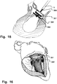
- Fig. 15 is a schematic illustration showing the medical device 300 inserted, circumflexing the chordae and providing a pre-annuloplasty downsizing of the mitral valve.
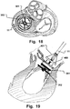
- Fig. 16 is a perspective view of a heart showing the situation of Fig. 15 in perspective. It becomes evident that the distal end of the medical device 10 advantageously is insertable into the interspace between the chordae and the myocardium.
- Fig. 17 is schematic illustration of another device providing pre-annuloplasty downsizing.
- the device 50 may for instance be a lasso, or similar, as described above.
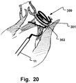
- Fig. 18 is a view from above showing another medical device providing downsizing and positioning of an annuloplasty prosthesis with a single delivery device 11.
- An annuloplasty prosthesis 400 may be arranged longitudinally movable along an elongated section of the delivery device 11. In use, the downsizing is first achieved by the loops 301, 302 as described above. The annuloplasty prosthesis 400 is then lowered into position and fixates the valve annulus. Subsequently, the annuloplasty prosthesis 400 is released from the tool 11, e.g. by cutting connection elements 401, such as threads or wires.
- Fig. 19 is a schematic lateral view illustrating the annuloplasty prosthesis and the medical device of Fig. 18 in the pre-annuloplasty downsized configuration prior to positioning and fixating the annuloplasty prosthesis.
- the medical device 10 does not carry the annuloplasty implant 200.
- the medical device 10 is inserted into position first. This positioning of the medical device 10 may be performed as described above with reference to Fig. 7 .
- the annuloplasty implant 200 may be inserted to the valve to be treated by means of conventional techniques for inserting an annuloplasty ring.
- the annuloplasty implant 200 is then sutured to the valve annulus in order to permanently keep the valve annulus 20 in its reshaped form. Thereafter, the medical device 10 may be withdrawn leaving the annuloplasty implant 200 in the patient.
- a kit for repairing a heart valve comprised of valve tissue including an annulus and a plurality of leaflets for allowing and preventing blood flow may comprise a medical device for facilitating a repair and/or replacement of a defective heart valve of a heart of a patient, the device comprising a downsizing element devised to automatically provide downsizing of an annulus of the heart valve upon insertion of the downsizing element into the heart; and an annuloplasty implant adapted to be attached to the heart valve annulus in order to reshape the annulus and allow the leaflets to open and close properly, and/or a valve prosthesis adapted to be attached to the heart valve annulus or the annuloplasty implant in order to allow the heart valve to open and close properly.
- the medical device may in specific examples be any of the above described medical devices comprising a downsizing element.
- the annuloplasty implant and/or the valve prosthesis may be arranged movable along the medical device upon the downsizing and into position for fixation to the annulus, and arranged releasably to the medical device for the fixation, such as described with reference to Figs. 18 and 19 .
- the annuloplasty implant and/or valve prosthesis may be releasably attached to the medical device by means of sutures, clips or staples.
- the downsizing device, annuloplasty implant and/or valve prosthesis may be patient configured.
- the device may be arranged to be withdrawn from the patient after the annuloplasty implant and/or valve prosthesis has been fixated to the valve tissue.
- the medical devices of examples may be used in a method for repairing and/or replacing a heart valve comprised of valve tissue including an annulus and a plurality of leaflets for allowing and preventing blood flow, the method comprising: inserting a medical device for automatically downsizing the annulus of the heart valve upon insertion of the medical device and prior to fixating an annuloplasty implant and/or valve prosthesis to the heart valve.
- the method may comprise accomplishing the automatically downsizing by means of a downsizing element of the medical device devised to provide the automatically downsizing of an annulus of the heart valve upon insertion of the downsizing element into the heart.
- the method may comprise accessing and circumflexing all chordae 26, 28 of the heart valve by the downsizing element and temporary repositioning the chordae 26, 28 of the heart valve by the downsizing element upon insertion thereof.
- the reposition of the chordae 26, 28 may comprise repositioning the latter towards a centre of the valve upon the insertion of the medical device to provide the downsizing.
- the inserting may comprise inserting a distal end of the medical device through a portion of the valve tissue, rotating the medical device to position the distal end on a first side of the valve, and downsizing the annulus from the first side of the valve.
- Fig. 20 is a schematic illustration of a medical device 300 providing downsizing via a ventricular access to a cardiac valve.
- a downsizing element is provided via ventricular access.
- the downsizing medical device 300 might be introduced transapically through a ventricle towards the valve.
- a surgical cut is made in the apex of the ventricle, and widened by a dilator, for access of the tool.
- the tool may then conveniently be inserted through the transapical opening, e.g. intercostally or from a sub sternal incision via an opening in the epicardium.
- the delivery device such as handle 11 is conveniently removed, and the incision is safely closed before finalizing the medical procedure.
- the downsizing element may be introduced via a transmuscular access through the ventricle wall. For instance when having overdilated heart muscle tissue, an aneurysm may occur. Such diseased heart muscle tissue is often surgically removed. Before closing the opening in the heart muscle, access is provided to the interior of the ventricle and to the heart valves.
- the downsizing element When the downsizing element is inserted into the ventricle, it may be rotated or change shape to circumflex the chordae 26, 45. Upon rotation towards the valve, downsizing is achieved. The medical device may then be further rotated, through a commissure of the valve, e.g. for delivery of an annulosplasty ring and/or artificial heart valve. Thanks to the anatomical arrangement of the chordae and commissures, the chordae automatically guide the distal end of the medical device 300 towards and into the commissure through the valve. This is in particular advantageous as performance of the procedure becomes very convenient.
- the downsizing element when inserted into the ventricle, it positioned distally through the valve. There it may change shape to the helical configuration. Upon rotation back towards and through the valve, downsizing is achieved.
- a correct size of an annulosplasty device and/or heart valve is provided. Hitherto surgeons determined the correct size by a trial and error principle, testing different sizes of annulosplasty devices until a correct one was found for implantation. This is now avoided.
- the correct size may be provided by a unit indicating the rate of downsizing, and choosing a corresponding annulosplasty device and/or heart valve.
- an annulosplasty device and/or heart valve may be affixed to the medical device 300, as described above. In this case, the annulosplasty device and/or heart valve automatically have the correct size, as the size is determined by the downsizing element.
- the downsizing element may be rotated into position.
- the correct downsizing is checked. If not satisfactory, a further up/down rotation is provided until an acceptable downsizing is provided by a correct coaptation.
- the downsizing element may then be removed, an annulosplasty device releasably fixed to it at a position for correct release at the downsized valve. Then the downsizing element is rotated back into the previously determined correct position, and the annulosplasty device is implanted or fixated to the annulus.
- a successful procedure may be tested by supplying a liquid into the ventricle, and subsequently pressurizing the ventricle. In this manner, a leakage is detectable by liquid passing a valve area, e.g. via a paravalvular leakage. Detected leakages may then be attended to. Leakages may for instance be prevented by using specific flange units on annulosplasty devices, such as described in PCT/EP2007/062225 .
- the access to the heart valve may be achieved endoscopically.
- the medical device 10 and/or the annuloplasty implant 200 need to be inserted through a narrow tube (catheter). This implies that the medical device 10 and perhaps the annuloplasty implant 200 will need to be compressed during insertion in order to pass through the catheter.
- the medical device 10 needs to assume its proper shape after having been passed through the endoscope. Therefore, using a catheter based approach, the medical device 10 should preferably be formed from a shape memory material. This allows the medical device 10 to be compressed and also to have a stable shape when being applied to the heart valve. Further, the annuloplasty implant 200 needs to be flexible in order to be compressed for the insertion through the endoscope.
- the medical device 10 may also be produced as a patient configured device. Production of the medical device 10 may for instance be based on production data derived from virtual planning a heart valve repair and/or replacement based on 3D image data, such as patient image data acquired by an image modality, such as Magnetic Resonance (MR) Imaging, Computed tomography (CT), or Ultrasound.
- MR Magnetic Resonance
- CT Computed tomography
- Ultrasound MR Imaging
- the medical device 10 may be produced at the patient examination site where the images are acquired, which save transport time. Alternatively, the production data may be generated or transmitted to a remote production site of the medical device 10.
- a patient configured device further minimizes the time needed for the medical procedure, providing all advantages related thereto.
- mitral regurgitation e.g. myxomatous degeneration of the valve, which is a genetic abnormality affecting the collagen that makes up the mitral valve. This causes a stretching out of the leaflets of the valve and the chordae tendinae. The elongation of the valve leaflets and the chordae tendinae prevent the valve leaflets from fully coapting when the valve is closed, causing the valve leaflets to prolapse into the left atrium, thereby causing mitral regurgitation.
- Ischemic heart disease may cause mitral regurgitation by the combination of ischemic dysfunction of the papillary muscles, and the dilatation of the left ventricle that is present in ischemic heart disease, with the subsequent displacement of the papillary muscles and the dilatation of the mitral valve annulus.
- Secondary mitral regurgitation may be present due to the dilatation of the left ventricle, causing stretching of the mitral valve annulus and displacement of the papillary muscles. This dilatation of the left ventricle can be due to any cause of dilated cardiomyopathy, including aortic insufficiency, nonischemic dilated cardiomyopathy and Noncompaction Cardiomyopathy. Dilated ventricles may be surgically treated by removing a portion of the ventricular muscle tissue.
Description
- The present invention generally relates to heart valve repair and/or replacement techniques, annuloplasty devices, and related tools. More specifically, the invention relates to a medical device devised for facilitating or providing such heart valve repair techniques and/or heart valve replacement techniques for the repair of defective heart valves.
- Diseased mitral and tricuspid valves frequently need replacement or repair of various reasons. The mitral and tricuspid valve leaflets or supporting chordae may degenerate and weaken or the annulus may dilate leading to valve leak (valve insufficiency). The chordae tendinae, or heart strings, in short called the chordae, are cord-like tendons that connect the papillary muscles to the tricuspid valve and the mitral valve in the heart. The leaflets and chordae may become calcified and thickened rendering them stenotic (obstructing forward flow). Finally, the valve relies on insertion of the chordae inside the ventricle. If the ventricle changes in shape, the valve support may become non-functional and the valve may leak.
- During heart valve replacement, sutures are spaced around the annulus (the point where the valve leaflet attaches to the heart) and then the sutures are attached to a prosthetic valve, see
Fig. 3 . The valve is lowered into position and when the sutures are tied, the valve is fastened to the annulus. The surgeon may remove all or part of the valve leaflets before inserting the prosthetic valve. - In heart valve repair, a defective valve is left in situ and surgical procedures are performed to restore its function. Mitral and tricuspid valve repair is traditionally performed with a suture technique, e.g. by performing the so-called Parachute procedure, see
Fig. 2 . - Heart valve repair and heart valve replacement may be performed in combination, e.g. a dilated leaflet may be partially surgically removed (e.g. leaving the chordae intact) and a heart valve replacement prosthetic valve may be affixed to the surgically modified anatomical heart valve in order to restore heart valve function.
- Frequently an annuloplasty ring is used to fixate an altered size of the annulus and/or support the annulus. The annuloplasty ring serves to keep the annulus in a reduced diameter and to allow the existing leaflets to oppose each other normally again, in order to restore correct valve function. Sutures are used to attach the prosthetic annuloplasty ring to the annulus of the heart valve and to assist in plicating the annulus. Before permanently attaching the annulosplasty ring to the annulus, the latter is prepared to the desired shape by other means than the annulosplasty ring. This preparation of the valve in order to achieve a correct geometrical arrangement of the anatomical entities of a heart valve, and a restored correct function thereof, is hitherto performed manually by a surgeon. This part of the procedure is also called downsizing, which is explained in more detail below. Furthermore, manual downsizing may be dependent on a line of sight or suitable imaging modalities.
- In addition, the form of the valve leaflets may be corrected by surgical techniques, e.g. tiny sutures, during the same surgical procedure. In general, the annuloplasty ring must be sutured to the valve annulus at the same time as a desired form of the latter is obtained at the end of the procedure. This simultaneous downsizing of the valve annulus and, which is time consuming and tedious. This means that two highly integrated processes are involved in the Parachute procedure, namely a) downsizing, perhaps including reshaping, of a dilated valve and b) a subsequent fixation of an annuloplasty ring. Thus, the Parachute procedure is highly dependent on the experience of the performing surgeon, who has to be able to think sterically, as it is necessary to firstly place the sutures on the annulus and then through the support ring.
- A result of such a procedure may differ greatly and even provide a non-desired result, very much depending on the skills of the surgeon performing the procedure. If the ring is severely malpositioned, then the stitches must be removed and the ring repositioned relative to the valve annulus during restitching. In other cases, a less than optimum annuloplasty may be tolerated by the surgeon rather than lengthening the time of the surgery to restitch the ring.
- During heart surgery, a premium is placed on reducing the amount of time used to replace or repair valves as the heart is frequently arrested and without perfusion. It would therefore be very useful to have a device and method to efficiently facilitate repair of heart valves or to facilitate attachment of a valve prosthesis into the mitral or tricuspid valve position.
- There is a need of improving this downsizing. It would be advantageous to be less dependent on the human factor. Moreover, the surgeons would welcome a device and method facilitating this crucial operation.
- In
WO2006/054930 , a device for repairing a heart valve is disclosed that comprises an implantation instrument. The implantation instrument comprises a first support ring, and a second support ring connected to the first support ring to form a coiled configuration. The first support ring is configured to abut one side of the valve and the second support ring is configured to abut an opposite side of the valve to thereby trap a portion of the valve tissue there between. The device further comprises an annuloplasty implant adapted to be attached to the heart valve annulus in order to reshape the annulus and allow the leaflets to open and close properly. The annuloplasty implant is connected to the implantation instrument for insertion to the annulus. The implantation instrument disclosed inWO2006/054930 provides already a major improvement of the previously known devices and methods. However, the devices and methods as disclosed inWO2006/054930 may further be improved as a primary reshaping for defining a working position of the insertion tool still has to be performed by the surgeon using a forceps instrument. Similar devices, suffering from analogous drawbacks are disclosed in e.g.US 2004/0167620 ,US 2005/0149178 , andWO 2007/030063 . -
US2007/0038293 discloses methods, devices, and systems for performing endovascular repair of atrioventricular and other cardiac valves in the heart. Regurgitation of an atrioventricular valve, particularly a mitral valve, can be repaired by modifying a tissue structure selected from the valve leaflets, the valve annulus, the valve chordae, and the papillary muscles. These structures may be modified by suturing, stapling, snaring, or shortening, using interventional tools which are introduced to a heart chamber. The tissue structures can be temporarily modified prior to permanent modification. For example, opposed valve leaflets may be temporarily grasped and held into position prior to permanent attachment. However, the disclosure ofUS2007/0038293 does only provide local modification of certain portions of a heart valve, e.g. by grasping one or more leaflets for bringing these into a position suitable for fixation of a clip to the leaflets. Hence, the motion of the valve leaflets is only partly and temporary immobilized. - In
WO 2006/093656 devices and methods are disclosed for aiding valve annulosplasty. The disclosed devices comprise a radiopaque deformable reference ring facilitating imaging based navigation of an annulosplasty procedure. However, the devices are not providing an active downsizing. Downsizing still has to be performed in a separate manner. - Therefore, there is a need to for devices and/or methods that further facilitate heart valve repair and/or replacement, e.g. by providing a suitable annuloplasty preparation of a cardiac valve area.
- Thus, there is a need to provide a tool or medical device that provides for a reliable and more easily accomplished valve repair or replacement. Facilitated, or less surgically demanding insertion of an annuloplasty implant and/or artificial heart valve would be advantageous. Hence, an improved tool, medical device or method would be advantageous and in particular a tool or method allowing for increased flexibility, user-friendliness, cost-effectiveness, and/or patient safety would be advantageous.
- Accordingly, embodiments of the present invention preferably seek to mitigate, alleviate or eliminate one or more deficiencies, disadvantages or issues in the art, such as the above-identified, singly or in any combination by providing a medical device and a kit according to the appended independent patent claims.
- In comparison with conventional annuloplasty, with the Parachute procedure, where the downsizing of a dilated valve and the reshaping as well as the fixation of the support ring are highly integrated into a tedious process, embodiments of the present invention provide for a separation (in time) of downsizing and reshaping. In particular, embodiments of the present invention provide for an advantageous downsizing, substantially simplifying the remainder of the valve repair or replacement procedure.
- Embodiments thus provide for both reducing complexity and time of previously known procedures.
- Thus, according to a first aspect of the invention, a medical device is provided for repairing and/or replacing a heart valve comprised of valve tissue including an annulus and a plurality of leaflets for allowing and preventing blood flow through a patient's heart. The medical device is arranged for facilitating the repair and/or replacement of a defective heart valve of a heart and comprises a downsizing element devised to automatically provide downsizing of an annulus of the heart valve upon insertion of the downsizing element into the heart. The downsizing element is a distal helical loop shaped downsizing element devised to automatically provide downsizing of an annulus of the heart valve upon insertion of the downsizing element into the heart, wherein the downsizing element has a first shape to facilitate access to circumflex substantially all chordae of the heart valve, and a second shape to reposition the chordae towards a centre of the valve upon the insertion to provide the downsizing.
- In the invention, the downsizing element has a first shape to facilitate access to circumflex substantially all chordae of the heart valve, and a second shape to reposition the chordae towards a centre of the valve upon the insertion to provide the downsizing.
- In a second aspect a kit is provided for repairing a heart valve comprised of valve tissue including an annulus and a plurality of leaflets for allowing and preventing blood flow. The kit comprises a medical device for facilitating a repair and/or replacement of a defective heart valve of a heart of a patient according to the first aspect of the invention, wherein the device comprising a downsizing element devised to automatically provide downsizing of an annulus of the heart valve upon insertion of the downsizing element into the heart; and an annuloplasty implant adapted to be attached to the heart valve annulus in order to reshape the annulus and allow the leaflets to open and close properly, and/or a valve prosthesis adapted to be attached to the heart valve annulus or the annuloplasty implant in order to allow the heart valve to open and close properly. An exemplary method is provided for repairing and/or replacing a heart valve comprised of valve tissue including an annulus and a plurality of leaflets for allowing and preventing blood flow. The method comprises inserting a medical device for automatically downsizing the annulus of the heart valve upon insertion of the medical device and prior to fixating an annuloplasty implant and/or valve prosthesis to the heart valve.
- The disclosure contemplates various examples of the medical device, including embodiments for catheter-based surgery and examples for open heart surgery. Another exemplary method is provided, comprising using the medical device according the first aspect of the invention in a medical procedure for repairing a heart valve comprised of valve tissue including an annulus and a plurality of leaflets for allowing and preventing blood flow through a patient's heart.
- Some examples provide for advantageous devices and/or methods for facilitating and/or providing treatment of regurgitation of mitral and tricuspid valves.
- Further embodiments of the invention are defined in the dependent claims, wherein features for the second aspect of the invention are as for the first aspect mutatis mutandis.
- Various additional objectives, advantages and features of the invention will become more readily apparent to those of ordinary skill in the art upon review of the detailed description of the illustrative embodiments.
- It should be emphasized that the term "comprises/comprising" when used in this specification is taken to specify the presence of stated features, integers, steps or components but does not preclude the presence or addition of one or more other features, integers, steps, components or groups thereof.
- These and other aspects, features and advantages of which embodiments of the invention are capable of will be apparent and elucidated from the following description of examples of the present disclosure, reference being made to the accompanying drawings, in which
-
Fig. 1a is a schematic cross-sectional view of a heart showing the arrangement of the heart valves; -
Fig. 1b is a cross sectional view of the left ventricle showing a mitral valve in perspective; -
Fig. 2 are perspective views illustrating the positioning of an annuloplasty ring by using the Parachute technique; -
Fig. 3 is a perspective view illustrating the positioning of a valve prosthesis by using the Parachute technique; -
Fig. 4 is a planar schematic view of a mitral valve with an annuloplasty ring successfully arranged thereon, post downsizing and reshaping; -
Fig. 5a is a lateral view of a medical device attached to a delivery device, here a delivery handle; -
Fig. 5b is a perspective view of the medical device ofFig. 5a in an enlarged view; -
Figs. 6a ,6b and 6c are detailed illustrations of the medical device according toFig. 5b with the delivery device detached; -
Fig. 7 is a schematic view of the medical device ofFigs. 6a-6c with an annuloplasty prosthesis attached thereto, in use at a heart valve tissue; -
Figs. 8a and 8b are schematic views of the medical device ofFig. 7 having a change of shape during use; -
Fig. 9 is a schematic illustration of another medical device for insertion to the ventricular side of a heart valve; -
Fig. 10 is a schematic illustration of at least a part of another medical device providing a change of shape during use; -
Fig. 11 is a perspective view of an embodiment of a medical device having an annuloplasty ring of the present invention attached thereto; -
Fig. 12 is a schematic illustration showing the insertion of the medical device ofFigs. 6a-c for downsizing a mitral valve; -
Fig. 13 is a schematic illustration showing the medical device ofFig. 12 inserted, circumflexing the chordae and providing the pre-annuloplasty downsizing of the mitral valve; -
Fig. 14 is a schematic illustration similar toFig. 13 showing the medical device of the present invention inserted, circumflexing the chordae and providing a pre-annuloplasty downsizing of the mitral valve; -
Fig. 15 is a schematic illustration similar toFig. 13 showing another medical device inserted, circumflexing the chordae and providing a pre-annuloplasty downsizing of the mitral valve; -
Fig. 16 is a perspective view of a heart showing the situation ofFig. 15 in perspective; -
Fig. 17 is schematic illustration of another device providing pre-annuloplasty downsizing; -
Fig. 18 is a view from above showing another medical device providing downsizing and positioning of an annuloplasty prosthesis with a single delivery device; -
Fig. 19 is a schematic lateral view illustrating the annuloplasty prosthesis and the medical device ofFig. 18 in the pre-annuloplasty downsized configuration prior to positioning and fixating the annuloplasty prosthesis; and -
Fig. 20 is a schematic illustration of a medical device providing downsizing via a ventricular access to a cardiac valve. - Specific examples of the disclosure will now be described with reference to the accompanying drawings. This invention may, however, be embodied in many different forms and should not be construed as limited to the examples set forth herein; rather, these examples are provided so that this disclosure will be thorough and complete, and will fully convey the scope of the invention to those skilled in the art. The terminology used in the detailed description of the examples illustrated in the accompanying drawings is not intended to be limiting of the invention. In the drawings, like numbers refer to like elements.
- The following description focuses on an embodiment of the present invention applicable to a repair of a defective heart valve and in particular to a reshaping the valve shape and/or area in order to facilitate insertion of an annuloplasty implant and/or artificial heart valve. However, it will be appreciated that the invention is not limited to this application but may be applied to many other heart valve disorders for which downsizing and/or reshaping of the valve shape and/or area is needed. For instance, a heavily dilated heart valve may be replaced with a heart valve prosthesis, wherein existing anatomical structures may be removed or partly removed. For instance, a part of the valve leaflets may be surgically removed, wherein it may be desired to keep as much of the leaflets as possible, e.g. without having to cut off the chordae. An anatomically correct size of the heart valve prosthesis is preferably chosen for providing a restoration of valve function, which may necessitates downsizing, i.e. reshaping the dilated valve shape and/or area, prior to fixating the heart valve prosthesis. This downsizing is provideable by embodiments of the present invention.
- The methods and devices are applicable for both downsizing of mitral and tricuspid valves.
- In conventional annuloplasty surgery a leaking valve, e.g. mitral valve, is adapted to a smaller diameter by means of a supporting ring, with a smaller diameter and/or area than the diameter and/or area of the leaking valve, and is fixated at a correct position by means of sutures (commonly by applying the tedious Parachute procedure illustrated in
Figs. 2 and3 ). As mentioned above, the Parachute procedure, sets demands on the performing surgeon, who has to be able to think sterically, as it is necessary to firstly place the sutures on the annulus and then through the support ring. The chance of failure is great. Furthermore, with the Parachute procedure, the downsizing of a dilated valve and the fixation of the support ring is a highly integrated process. An improvement provided by some examples of the present disclosure might be described as a separation (in time) of these two events; downsizing, and fixation. Thus, examples provide for reducing both complexity and time for the combined procedure. - The term "downsizing" as used in the present specification is to be understood as an alteration of a heart valve, e.g. for a pre-annuloplasty, by means of
- 1) changing the shape or contour described by the heart valve annulus, or
- 2) changing (i.e. reducing) the area described by the annulus, or
- 3) both 1) and 2).
- These changes might be in a two dimensional plane or in a three dimensional plane.
- A successful downsizing may be appraised by the leaflets of a heart valve having regained proper coaptation. Hence, some examples of the disclosure provide a restored proper coaptation of heart valve leaflets. This may be permanently fixated by annuloplasty implants subsequently fixated to the annulus of the heart valve. In addition, or alternatively, some examples of the disclosure provide a permanent downsizing and are left in place in the body. In addition, or alternatively, some examples of the disclosure may provide an improved, restored or proper leaflet coaptation that in addition is permanently supported by an artificial heart valve, in order to provide proper heart valve function.
- The aspect of downsizing, as defined above, may be performed in many ways. Some may be more suitable at specific circumstances although not applicable in others. Within the interior of the heart some anatomical structures may be pushed, pulled or stretched to enforce a reshaping of an adjacent valve, i.e. the chordae, the leaflet or the annulus may be manipulated accordingly to achieve the desired downsizing of the heart valve. When the desired downsizing is achieved, the heart valve may be permanently fixated in this shape and/or area by suitable elements, such as annuloplasty devices, or by leaving a downsizing element permanently in its position.
- "Heart valve repair" as used in this specification may include heart valve replacement. Heart valve repair may comprise installation of artificial heart valve prosthesis. For instance, a dilated heart valve leaflet may be partially surgically removed (e.g. leaving the chordae intact) and a heart valve replacement prosthetic valve may be affixed to the surgically modified anatomical heart valve in order to restore heart valve function. Also, an artificial heart valve prosthesis may be attached to an annuloplasty device. Downsizing is thus alternatively or in addition to fixation of annuloplasty devices provided prior to fixation of artificial heart valves. Some examples provide for advantageous heart valve repair, as e.g. described with reference to
Figs. 18 and 19 . -
Figs. 1a and1b are given for illustrating the anatomical situation where examples of the disclosure are implementable.Fig. 1a is a schematic cross-sectional view of a heart 1 having atricuspid valve 2 andtricuspid valve annulus 3. Themitral valve 4 is shown adjacent amitral valve annulus 5. Themitral valve 4 is a bicuspid valve having ananterior cusp 7 and aposterior cusp 6. Theanterior cusp 7 and theposterior cusp 6 are often referred to, respectively, as the anterior and posterior leaflets.Fig. 1a also shows theaorta 15, which is located adjacent the wall of the left atrium on the anterior side of the mitral valve. Also shown in the figure are theposterior commissure 17 and theanterior commissure 18.Fig. 1b is a cross sectional view of the left ventricle showing themitral valve 4 in perspective.Fig. 1b illustrates a patient 10 having a heart 12 shown in cross section including aleft ventricle 14. The concepts of the present invention are suitable to be applied, for example, to amitral valve 18 which supplies blood intoleft ventricle 14.Mitral valve 18, as better shown inFig. 1a , includes an annulus 20 and a pair ofleaflets left ventricle 14. It will be appreciated that the term annulus tissue is used extensively throughout this disclosure in reference to the drawings, however, the inventive principles are equally applicable when referring to other valve tissue such as leaflet tissue or other attached vessel tissue.Leaflets chords papillary muscles left ventricle 14 through themitral valve 4 and is expelled during subsequent contraction of the heart 12 through theaortic valve 34. It will be appreciated that the present invention is applicable to tricuspidal heart valves as well. - Downsizing methods and devices will now be described in more detail.
- In examples, a medical devices collects the chordae, or bundles of chordae, for providing a downsizing of the corresponding adjoining heart valve. Some examples collect at least substantially all the entire chordae in a single working operation.
- In more detail, the medical devices comprise a downsizing element devised to automatically provide downsizing of an annulus of the heart valve upon insertion of the downsizing element into the heart. Insertion may be performed from the atrial side or the ventricular side of the valve.
- In the disclosed invention, the downsizing element is arranged to automatically reposition the
chordae - Specific examples of chordae manipulating downsizing elements will now be described.
- In the invention, medical devices are provided that are arranged and comprise one downsizing element to physically circumflex around substantially the entire chordae tendinae of a valve, gripping the latter in a gentle manner such that a distinct temporary downsizing of the valve is automatically provided by inserting the medical device accordingly. Furthermore, the downsizing element has a first shape to facilitate access to circumflex substantially all
chordae chordae chordae chordae - In a superior view of the heart the valves are blocking the view of the chordae tendinae, as shown in
Fig. 1a . However, the anatomy of the valve makes it possible to go beneath a valve, e.g. through a commissure thereof or by penetrating the annulus thereof, and thereby reaching an anatomical space near the valve between the wall of the heart and the chordae tendinae. Thus, the chordae may be collected within a helical device comprising the distal loop shaped element, whereby the chordae may be drawn together for downsizing the valve, upon insertion of the device. Downsizing is thus provided by making use of the helix-shaped device. - In an example the helical device has a helical structure that is arranged on an imaginary cylinder and where a defined distance is kept between subsequent turns of the helix, i.e. a hollow centre and a free space is provided between each turn.
- The helix may have a blunt tip in order to not harm the anatomical structure of the heart. The tip of the device may be arranged with a larger diameter than the subsequent part of the helix that circumflexes the chordae.
- The device may be inserted through either commissure at a valve or penetrating through the valve annulus, whereby the chordae tendinae will be circumflexed by the helical structure as the device is inserted continuously. The diameter of the helical structure, i.e. diameter of the imaginary cylinder, is defined prior to insertion and set smaller than corresponding value of the valve, hence the valve will be downsized as the helix is inserted and circumflexing all of the chordae tendinae.
- In more detail, the helical device comprises the distal helical loop shaped element, which thus is "loop-shaped" with an open distal end. The loop shape is provided as a curved shape that is continuous towards a proximal part of the device, e.g. with a circular, elliptic, or D-shaped form or any other curvature which may provide a suitable downsizing of the shape of the valve annulus. The term "loop-shaped" also includes a curved shape that is open forming an arcuate shape, such as a C-shape or U-shape. The term "loop-shaped" also includes a curved shape overlapping itself to form a portion of a coil. The term "loop-shaped" also includes three dimensional curves as mentioned in the previous paragraph. The number of loops of the helix may be different and vary from e.g. a half turn (e.g. C-shape or U-shape) up to several turns.
- The cross section of the helix may differ along the longitudinal extension of the helix in some examples.
- Some examples may be provided for catheter-based surgery, for transvascularly introducing into position. Some examples may be provided for open heart surgery, e.g. in a rigid configuration.
- Several loop shaped examples are described in more detail below with reference to
Figs. 5a to 19 . - A catheter and/or wire may be fed generally axially into place around the entire, or at least substantially the entire chordae (either through the leaflets from the atrial chamber or from the ventricular side of the valve).
- In the case of using the catheter, e.g. a wire is fed into the central lumen to form the catheter to the desired curvature around the chordae, gather the chordae, and alter the curvature of the valve annulus, generally to a smaller diameter or radius through at least a segment of the annulus circumference. The wire may for instance be pre-shaped, spring formed, memory biased, tension wound or braided, plastic polymer formed, in order to achieve the desired curvature.
- A wire of pre-formed shape may also be provided and used to change the shape of the catheter upon axial rotation of the wire after it has been fed into the catheter.
- In another example, the catheter may also be altered in shape or curvature as a result of fluid (gas or liquid) pressure or vacuum exerted on the inner lumen of the catheter, as in the case of a balloon catheter. In this case, the catheter may be provided as shape biased to curve under pressure applied to the central lumen or when pressure or vacuum is applied to one of a plurality of lumen, creating a high pressure distended lumen and/or a low pressure contracted lumen, as desired, in order to circumflex, grab and modify an anatomical structure, such as the entire chordae of a heart valve.
- In the case of the wire initially placed as a guide around the chordae, a sleeve or catheter of a desired curvature may be fed over the wire and around the chordae to gather the chordae and alter the curvature of the valve annulus, generally to a smaller diameter or radius through at least a segment of the annulus circumference. The catheter may for instance be pre-shaped, spring formed, memory biased, tension wound or braided, plastic polymer formed, in order to achieve the desired curvature.
- A sleeve or catheter of pre-formed shape may also be used to change the shape of the catheter upon axial rotation of the sleeve or catheter after it has been pushed over the wire.
- In addition to pre-shaped wires, catheters or sleeves, actively steerable wires or catheters may be provided and used to modify an anatomical cardiac structure for achieving a downsizing. For instance, in case the annulus does not have a smooth path, abrupt change in direction or is extensively elongated or presents some other irregularity, a steerable device may be provided. As the path may be blocked, while inserting the device through a commissure, small adjustments of e.g. the direction of the tip of the device may steer and overcome the obstacle. Insertion of a helical device via either commissure and rotating the device, e.g. a full loop, i.e. a 360 degree turn, parts thereof, or multiples thereof, introduces the device in the interspace between the heart muscle wall and the chordae tendinae. Thus the entire, or at least substantially the entire chordae tendinae are circumflexed by the device, as e.g. illustrated on the right in
Fig. 17 showing amedical device 50 circumflexing the chordae and downsizing a heart valve annulus. - After this initial procedure the actual retraction of the chordae tendinae towards the centre of the annulus may be already be achieved by the shape of the medical device. Alternatively, or in addition, the retraction of the chordae may be provided by an electroactive system implemented within the device. Intrinsic parts of the device may be activated by electric energy. The total length of the device may be shortened in this manner, and hence its circumference gets smaller, resulting in a downsizing of the annulus. The device may be configured to be elongated on its outer while it is shortened on the inside or only one of these configurations. The effect is that the device will get a curvature, bending in the direction of the device gets shorter.
- Tendons or tension elements may be used in an inner lumen of a catheter structure to generate a compressive force on one side of a catheter wall in order to provide a controllable curvature of the catheter. Tension in the tendon is for instance generated by a screw or pully mechanism, remotely operated e.g. in the catheter handle. The curvature of the distal catheter tip is determined by the form of the catheter wall itself, e.g. its wall thickness, notches or features to allow flexibility in the catheter. In
US 6,976,987 , a dual profile steerable catheter is disclosed, which is used for treating e.g. cardiac arrhythmia. The catheter has tendons housed within a sheath such that a movement of tendons in proximal direction causes a distal end region of the sheath to deflect. - However, such a steerable catheter has hitherto not been provided or used for downsizing purposes. A steerable catheter may be fed generally axially into place around the chordae, either through the leaflets from the atrial chamber or from the ventricular side of the valve, and the shape of the catheter may be altered, e.g. using tendons, to form the catheter to the desired curvature around the chordae, gather the chordae, and thus alter the curvature of the valve annulus, generally to a smaller diameter or radius through at least a segment of the annulus circumference.
- In a similar sense, elements may be provided and used to create a pushing force, instead of a pull, in a catheter lumen to deflect the catheter or a downsizing element of the medical device.
- The shape of the medical downsizing device may be actively controlled, e.g. by electroactive polymers. Electroactive polymers are known to increase or decrease in bulk volume, which may be used to create expansion or contraction forces on one side or another of a catheter lumen.
- In
US 7,261,686 , an universal, programmable guide catheter for coronary treatment is disclosed, which comprises electroactive polymer actuators to change shape of the catheter based on control signals received from a control unit. InUS 7,128,707 , electroactive polymer based artificial sphincters and artificial muscle patches are disclosed for treating, e.g. fecal incontinence, which has a cuff for placement around a body lumen and electroactive polymer actuator. A control unit is provided for controlling the actuators to expand or contract the cuff. The artificial muscle patches, which are adapted to be implanted adjacent a patient's heart, and the artificial sphincter cuffs are adapted to be implanted around a body lumen, such as the urethra, the anal canal, or the lower esophagus. - However, such electroactive polymer actuators have hitherto not been provided or used for downsizing purposes. A construction comprising electroactive polymer actuators may for instance be provided at a catheter tip or distal portion of a partly flexible helical downsizing device, allowing for gathering anatomical structures like the chordae and downsizing of a heart valve annulus.
- Rotating elements may be used for changing the curvature of downsizing elements. For instance the above mentioned wire may comprise sections of elements rotatable relative each other with an inclination angle, thus leading to a curvature of the wire controllable by rotating the latter, e.g. in relation to a distal end of the wire fixed to a catheter sheath. The downsizing element may be introduced through a commissure and be guided in between the wall of the heart and the chordae tendinae. As a full 360 degree rotation is completed the outer most end of the inserted device returns to the commissure and site of entrance.
- The thread tip may be pulled as a lasso structure, whereby gently applying a pulling force to the ends of the thread will downsize the valve in respect to the amount of force applied.
- The alteration of a valve may be provided by pulling the outer rim of the leaflet by means of a forceps device. The reduction in size of the valve depends on the applied force, on each leaflet, and on the overall rigidity of the anatomic structures of the heart surrounding the specific valve in question. The valve may be altered to a larger extent in the transversal than in the longitudinal direction by the method; however it will depend on how the applied force is distributed across the annulus. For instance, using at least one forceps for each leaflet to grab gently the edge of each leaflet and pulling the edges towards each other, the size of the valve may be altered. This downsizing using forceps may be performed automatically, e.g. robot based and/or ultrasound feedback controlled.
- Another approach is to apply an adjustable tape pulling the annulus. With an adhesive surface a strip may be attached to the leaflets, thus securing a firm grip, whereby the leaflets may be pulled toward each other. The adhesive must be designed for biological tissue to have a desired effect of firmly attach to the leaflet. By using more positions where the force is applied for each leaflet, the pulling force may be more evenly distributed across the leaflet base, whereby the valve is smoothly reshaped, and a downsized valve results. This downsizing using adjustable tapes may be performed automatically, e.g. robot based and/or ultrasound feedback controlled.
- Another method may comprise attaching arms to the annulus, i.e. distal the leaflet edge, and applying a pulling force with these arms. Thus the size and/or area of the valve may be altered. The arms may have barbs or an adhesive surface at the outer end securing a firm grip at the annulus. The effect is dependent on how firmly the arms are anchored at the annulus and the numbers of arms, the amount of force applied and the overall rigidity of the heart surrounding the annulus. This downsizing using arms may be performed automatically, e.g. robot based and/or ultrasound feedback controlled.
- An "Alfieri" type repair for mitral insufficiency may be performed by suturing the free edges of the leaflets together thus generating a double orifice appearance. The procedure is performed by open heart surgery and may be suitable in downsizing a valve temporarily.
- Percutaneously similar results are found by using Mitraclip (Evalve Inc., Redwood City, CA, US). The device, a fabric covered clip capturing both free edges of the leaflets, is delivered by a transseptal catheter creating a double orifice. However, the valve annulus has hitherto not been modified or downsized when using the Mitraclip devices. Furthermore, the Mitraclip devices did hitherto not allow for an automatic pre-annuloplasty change of shape of the annulus for facilitating the annuloplasty procedure.
- Additional methods are available using the Mobius device (Edwards Lifesciences, Irvine, CA, US) which captures the free leaflets via a transatrial guide catheter. The process uses a vacuum port to secure the leaflet and a needle places a suture. The process is then repeated for the adjacent leaflet. As both leaflets are captured they are drawn together and a small clip securing the suture finishes the procedure. However, also the Mobius device has hitherto not been used for downsizing.
- Encircling collars may be provided for downsizing purposes, e.g. in form of lassos, clamps or cuff collars, as explained below.
- A lasso may be placed around the valve chordae, either through the leaflets from the atrial chamber or from the ventricular side of the valve. The chordae may then be gathered, and the curvature of the valve annulus altered, generally to a smaller diameter or radius through at least a segment of the annulus circumference, i.e. a downsizing is achieved. An automatic downsizing to a desired degree of downsizing may be achieved by providing a suitable end position or stop of the lasso.
- In
US 7,297,144 , methods for electrically isolating a portion of the atria are disclosed. In particular, drawing items 140 & 142 on cover page or sheet 13 describe a lasso. - In
US 6,123,703 , an ablation catheter and methods for treating tissues are disclosed. In particular on drawingsheet 7 or 8 ofUS 6,123,703 a deployable closed loop is shown. However,US 6,123,703 deals with an ablation catheter system for treating tissues or atherosclerotic tissues of a patient. The catheter system has a retractable metallic element means comprising the deployable close loop with a running noose at its end, and the ablation catheter provides RF therapy to the tissues through the retractable metallic elements means. - However, such a lasso or closed loop has hitherto not been provided or used for downsizing purposes.
- A clamping device may be positioned around the external features of the heart, e.g. around the atrial-ventricular (AV) groove or on the left ventricular free wall to push in the valve annulus anatomy and bring the annulus into the desired shape for placement or a prosthetic device. The clamp may be in the form of at least one and perhaps two opposed clamping surfaces. The clamp may have a shape to match the desired heart anatomy. The clamp may be drawn together like a screw clamp or forced together in a tong like device. An automatic downsizing to a desired degree of downsizing may be achieved by providing a suitable end position or stop of the clamp(s).
- A clamping collar may be positioned around the external features of the heart, probably around the AV groove or on the left ventricular free wall to push in the valve annulus anatomy and bring the annulus into the desired downsized shape for placement of a prosthetic device. The collar may be in the form of at least one, such as two opposed, encircling band elements. The collar may be of a shape to match the desired heart anatomy. The collar may be drawn together like a lasso, or be forced together in a tong like device or screw clamp device.
- The cuff may be similar cuffs developed by Acorn Cardiovascular and Paracor to restrain the heart from further dilation, namely the HeartNet™ Device. The cuff device may be used to form the heart into the desired shape to shape the valve annulus appropriately for prosthetic device placement or another form of repair. An automatic downsizing to a desired degree of downsizing may be achieved by providing a suitable end position or stop of the cuff or collar.
- From the surface of the heart muscle force may be applied, reshaping the anatomic configuration of the myocardium. For the mitral valve it is possible to use the adjacent sinus coronaries as an access path, which is reachable via a minimal invasive method.
- Long-term therapeutic devices using this access path for treating mitral insufficiency are e.g. disclosed in
WO02/062270 WO02/062270 - Various shape effecting devices may be placed temporary in the sinus coronaries for a temporary downsizing effect facilitating an annuloplasty procedure. After terminating the procedure, the devices are then removed from the coronary sinus.
- Tendons may be used for changing the shape of a medical device, such as shown in
Fig. 10 . In some examples of this type, the downsizing element comprises a plurality ofsegments 312 moveable in relation to each other, and atendon 314 inserted along the plurality ofsegments 312, wherein the tendon is distally attached to a distal end portion of the downsizing element, such that the downsizing element decreases radially at least along a portion thereof upon pulling at a proximal portion of thetendon 314. - Electro active elements, e.g. polymeric elements as described above may be provided in elongate elements insertable into the sinus coronaries.
- Rotating elements may be used for changing the curvature of downsizing elements insertable into the coronary sinus.
- The above examples for insertion into the coronary sinus may make use of a temporary fixation element for facilitating the desired change of shape of the downsizing elements. For instance an inflatable balloon may be provided at a distal end of the device. Upon inflating the balloon, a fixation point is provided and the flexion of the temporary downsizing element is facilitated. When the annuloplasty procedure is finalized, the balloon is deflated again and the downsizing element is removed from the coronary sinus.
- Like the sinus coronaries, the circumflex artery may be used as an access path for temporary downsizing elements, devices or assemblies adapted for downsizing of an adjacent heart valve.
- The myocardium (heart muscle) may be exposed to a stimulating element or agent resulting in a local contraction thereof providing a temporary downsizing. This may be provided both minimally invasive or during open chest cardiac surgery.
- The stimulation may be provided by electrical charges delivered locally to the myocardium, e.g. by means of an electrode. The electrode may be positioned in a catheter based minimally invasive manner.
- It is well known in the art that low temperature lowers the metabolic rate, in case of the heart the activity will slow down and time is gained whereby the surgery can be extended without damaging the heart. Cooling down the myocardium to approximately 22-24 degree Centigrade is used commonly during open heart surgery to cool down the entire heart.
- Locally cooling down the cardiac tissue may be used to provide downsizing a valve annulus temporarily.
- Various chemical substances or pharmacological agents may affect the contraction of the myocardium and provide downsizing of a valve annulus. The substances or agents may be delivered to the desired cardiac target site by a syringe needle or a hollow catheter e.g. having a hollow steerable needle tip, e.g. a smart needle.
- A further stimulus providing a temporary downsizing is radiation, e.g. from a radio frequency source.
- Chordae tendinae are approximately 80% collagen, while the remaining 20% is made up of elastin and endothelial cells. By means of the above stimulations (temperature, chemical, RF), a part of the collagen may be temporary removed from the chordae for the downsizing. Collagen is rebuild after a certain time and restores function of the chordae.
- It may be suitable to temporary compress a free wall of the ventricle to reshape the dimension of the heart. The compression delivers a force uniformly over the area whereon the cuff is placed. With correct placement the shape of the annulus is affected, and downsizing of the same may be achieved.
- The myocardium may be elongated, with the use of an external force, whereby the circumference of the myocardium at a cross-sectional plane close to the mitral valve and tricuspidal valve is reduced. Hence, these valves will be reshaped, and a downsizing may be achieved.
- The force may be of a mechanical origin, as applying a pulling force at the apex cordis while fixating the superior part of the myocardium. The fixation of the pulling device at the apical area of the heart must be firm as well as gently in order not to harm the tissue.
- In a similar setup, the force for fixation of the apical area may be provided utilizing a suction cup. By providing a vacuum, a secure fixation may be reached. Still a fixation of the superior part of the myocardium must be firm. While applying a pulling force at the apex cordis the rim of the suction cup together with the smoothness of the heart surface set boundaries to the amount of force the transition zone can bridge.
- The heart muscle may be mechanically fixated by one or several pins though the whole extension of the heart, as well as the chordae. As the heart is fixated it may be compressed by applying force at each pin end, in a direction towards the centre of the heart. With suitable position of these pins a valve and corresponding annulus may be affected by the applied force, whereupon the valve is reshaped, and a downsizing may be achieved.
- It may be suitable to temporary compress an atrium to reshape the superior dimensions of the heart. The compression may provide a force uniformly over the area whereon e.g. a cuff is placed. With correct placement the shape of the annulus is affected, and downsizing of the latter is achieved. Externally to the heart, ribbons or flexible bands may be positioned near or on top of the sinus coronaries to restrain the mitral valve. As the ribbon is tightened a compression force is applied to the mitral valve which may reduce its size. The method is however more rough than corresponding compression utilizing a cuff arrangement mainly because of two reasons: ribbons are most often small in width which may damage the tissue as the ribbons get tightened and the heart tissue may be callipered at the junction as well.
- With use of the aortic wall as a backbone, support, for a balloon, displacement of the aorta septal wall may be possible. The balloon will upon inflation, either by fluid as saline or other non-harming fluid or gas, induce a force towards the heart thereby causing a displacement of the heart structure. Although, the amount of displacement is dependent on the overall rigidity of both the heart muscle and the aortic wall. However rupture or weakening the aorta must be avoided.
- In a similar manner as the chordae tendinae may be circumflexed by devices and methods described herein, one or more papillary muscles may be circumflexed. For instance a lasso may be positioned around a single papillary muscle, or several papillary muscles, or all papillary muscles. Pulling the ends of the lasso arrangement and drawing towards the cardiac apex, i.e. away from the heart valve, may provide downsizing thereof. Helical devices may be provided and used for this purpose. An access way for such a device and method is via the apex through the myocardium. Transapical access is described below in more detail.
- The parachute technique may be simplified by examples of the present disclosure. The downsizing of an annulus may be provided prior to placing the sutures carrying an annuloplasty prosthesis. In this manner, the surgeon does not need to take into consideration a further change of shape of the annulus imposed by the position of the sutures. The alignment of the annuloplasty prosthesis is thus facilitated and the parachute procedure substantially simplified. For instance, the helical device is provided and used for this purpose.
- For the parachute procedure, both ends of a single suture are sutured through the natural annulus, taking a relatively large gap between the needle penetration points. The two ends of this same suture are then passed through the prosthesis. The prosthesis is held away from the natural valve annulus during this procedure to allow easy access to the downsized annulus and the prosthesis. The prosthesis is easily aligned to the downsized annulus during this procedure, as the downsized annulus has a shape or contour adapted to that of the annuloplasty prosthesis. The suturing pattern is repeated using additional sutures, resulting in several suture "pairs" spaced around the downsized annulus. The prosthesis is then lowered or parachuted down against the downsized annulus. After all the suture pairs are secured, the result is a reduced annular circumference with an attached prosthesis. The downsizing medical device providing the downsizing may then be removed as the prosthesis now fixates the downsized shape permanently.
- Percutaneous methods and techniques that may be applicable in downsizing a heart valve may be used. Even at open surgery it may be feasible to address the heart by some catheter based therapy. Access routes for the downsizing devices comprise the following routes, including catheter based therapy:
- A path to reach the mitral valve is by applying a transaortic approach entering the myocardium on the arterial side, reaching the mitral valve from beneath, the valve is up-stream. The specific method is chosen to downsize the valve may be some of the above mentioned.
- Another path to reach the mitral valve is by a trans septal approach, entering the myocardium on the venous side at the vena cava. The mitral valve is reached from beneath. The specific method chosen to downsize the valve may be some of the above mentioned.
- From the venous side the heart is reached via vena cava and entering the left atrium. The tricuspid valve is reached from above, trough the leaflets. The specific method chosen to downsize the valve may be some of the above mentioned.
- In
WO2005/104957 , it is disclosed how the mitral valve and the tricuspid valve can be reached from beneath by entering at the apical area of the myocardium, hence the valves are reached from below. It is suggested to enter percutaneously at the thorax at the fifth intercostal space, at the left side of the chest, other suitable entrance position are suggested as well. The suggested approach to reach the heart valves give possibilities to use larger surgical equipment than usually at percutaneous procedures. The lumen of the vessels normally sets an upper boundary on the equipment size. As the suggested approach of entrance is directly trough the apical area of the heart, restrains are set by this anatomical structure. The specific method chosen to downsize the valve may be some of ones mentioned herein. A further detailed example of this access path is given below. - Now turning to
Figs. 5a to 6c , an example of a medical downsizing device is described in more detail.Fig. 5a is a lateral view of amedical device 10 according to an example of the disclosure, attached to adelivery handle 11.Fig. 5b is a perspective view of themedical device 10 ofFig. 5a in an enlarged view.Figs. 6a ,6b and 6c are detailed illustrations of the medical device according toFig. 5b without the delivery handle. - The
medical device 10 is a pre annuloplasty downsizing device of the kind that is above referred to as helical or loop shaped device. - In more detail, the
medical device 10 is a tool adapted to downsize a heart valve annulus for facilitating an annuloplasty procedure. Themedical device 10 comprises a first and a second loop shaped,helical element proximal end 104 for releasably attaching a handle 20, and adistal end 101 in insertion direction of themedical device 10. Thus, the handle may be disengaged from themedical device 10. The cone shaped coil may resemble a spiral, helix like or keyring-type configuration. The second loop shaped element is connected to the first loop shaped element to form a coiled configuration, wherein the second loop shaped element is configured to be positioned on a second, opposite side oriented towards an atrium of the area of the valve tissue to thereby arrange the valve tissue between the first loop shaped element and the second loop shaped element, and wherein the second loop shaped element comprises at least one fixation element for releasable attachment of an annuloplasty implant or a heart valve prosthesis. - The first and a second loop shaped,
helical elements distal end 101 of the helicalmedical device 10 is introduced at a commissure of the valve and rotated further for reaching its final position of use with the twohelical elements medical device 10 is explained in more detail below with reference toFigs. 12 and 13 . - The
medical device 10 may comprise elements facilitating temporary fixation of other devices to themedical device 10. For instance through-holes 105 in the loop shaped elements, or selected portions thereof, may provide temporary fixation of other elements, such as an annuloplasty implant, and/or a heart valve prosthesis to themedical device 10, e.g. by means of sutures. In addition or alternatively other fixation means may be used for this purpose, such as clips, releasable staples, bands, etc. Also, the other element itself may be devised for the temporary fixation, e.g. by having a spring function temporary grabbing around one of the loop shaped elements. Upon delivery the other element may thus be removed from themedical device 10 to the site of implantation, e.g. by removing the fixation means, such as sutures, clips, etc. or by turning over, stretching, expanding, etc. the other element from themedical device 10 for fixation to the anatomical structure at the implantation site. - In some examples of the medical device, the
distal end 101 is shaped in such a manner, that it catches the chordae (26, 28 for the mitral valve) by advancing between the chordae and the opposite cardiac muscle tissue 12. Thus thedistal end 101 is arranged for catching the chordae inside the firsthelical element 102. Thedistal end 101 may for this catching purpose be directed radially outwards or axially downwards from a diametric plane of the secondhelical element 103. - The tip of the
distal end 101 may be blunt, e.g. rounded, or provided with a spherical element. This provides for advantageous catching the chordae without risking injury or damaging the chordae or ventricular tissue. - At the
proximal end 104, the device is provided with a connection interface for releasably attaching a delivery device, such ashandle 11, such that a handling, direction and rotation is provideable to themedical device 10 in use thereof. In some examples, the delivery handle may be integral with themedical device 10. Theproximal end 104 is arranged substantially perpendicular to a plane diametric to the loops of themedical device 10. Theproximal end 104 may be arranged along a longitudinal axis imaginary arranged perpendicular to the plane diametric to the loops and in a center of the loops. Alternatively, the proximal end may also be arranged off-center, depending on the patient specific anatomical situation. - From the
distal end 101 towards the connected secondhelical element 103, the body of the present example of themedical device 10 extends along the firsthelical element 102 with a reduced radial extension. In this manner, upon further introducing themedical device 10, by rotating the latter, e.g. using thehandle 11, in the rotational direction of thedistal tip 101, the entire chordae of a heart valve are circumferentially gripped and upon rotation gradually moved towards the center of themedical device 10, defined by a longitudinal axis thereof. When one or more of the helical elements of the medical device has a non circular form, such as shown inFigs. 6a to 6c , the movement of the chordae for the downsizing is dependent on the rotational direction of themedical device 10 in relation to the longitudinal axis of themedical device 10. - The effective turns (as e.g. shown in
Fig. 12 and 13 ) needed for providing a desired downsizing may be variable, including parts of turns, depending on the shape characteristics of the helical elements, e.g. their pitch, amount of taper of the helical windings, etc. For instance, the examples of the medical device may be rotated in full turns, quarter turns, half turns, multiple turns etc. In addition, or alternatively, a non-circular shape of at least a part of the helical windings may be used for providing a desired variable downsizing effect, depending on the degree of rotation when introducing themedical device 10. For instance, a D-shapedmedical device 10, as illustrated inFigs. 6a to 6c , may advantageously provide downsizing in a preferred direction, e.g. between the anterior side and the posterior side of the heart valve, e.g. for changing the shape of the mitral valve annulus in such a manner that two valve leaflets of the mitral valve are pushed towards each other without compressing the valve leaflets in the longitudinal direction thereof. - In some examples, an
annuloplasty ring 200, seeFigs 7 or11 , may be temporary attached to the secondhelical element 103 and thus conveniently arranged for fixation to the valve annulus. Fixation of an annulosplasty ring to a valve annulus is e.g. described inWO2006/054930 . Holes may be provided in the secondhelical element 103 for providing temporary fixation points for theannuloplasty ring 200 to themedical device 10. For instance inFig. 11 , the fixation is illustrated with sutures that are removed upon downsizing of the valve annulus by means of the firsthelical element 102 and positioning of theannuloplasty prosthesis 200 at the annulus.Fig. 7 is a schematic view of the medical device ofFigs. 6a-6c with an annuloplasty prosthesis attached thereto, in use at a heart valve tissue. - The
distal end 101 of the medical device is introduced through the commissure and is rotated to position, passing in between the heart muscle wall and the chordae. As the diameter is decreasing the chordae are pulled inward to the centre of the medical device and thus of the valve. Thus the valve annulus has been downsized to a desired degree allowing fixation of the shape and area thereof, e.g. by means of theannuloplasty prosthesis 200. When theannuloplasty prosthesis 200 is removed from themedical downsizing device 10 and fixated to the valve annulus, themedical device 10 is counter rotated and then withdrawn from the patient. - In this manner, a downsizing of the valve is automatically achieved in one step and the desired shape and area of the valve is provided for long-term fixation, e.g. by an annuloplasty ring.
- In some examples, the downsizing may also be achieved in a long-term perspective for therapeutic purposes, thus further facilitating and simplifying the repair of valve regurgitation. In these examples, the medical downsizing devices are left in place at the termination of the medical valve repair procedure. This may be provided by disengaging a delivery unit, such as a handle or a catheter wire, from the downsizing element.
- Any suitable medical grade material(s), such as medical grade metals or plastics, may be used to form the
medical device 10. In some examples themedical device 10 may have a traditional cross sectional shape associated with a keyring. In this example flat, opposed surfaces are arranged to be positioned on either side of a valve annulus tissue 20, the first ring in the cardiac chamber and the second ring in the atrium. The opposed surfaces 45 may also be roughened in order to improve engagement with the valve annulus 20. Viewed cross sectional, perpendicular to the longitudinal axis of the helical structure, the various examples of the disclosure may have a variety of geometric appearances e.g. circular, oval. Some examples may comprise changes of the cross sectional geometric form along the length of the medical device, e.g. the first and/or second ring may have different geometric shapes and varying cross sections, at least at portions thereof. - The
annuloplasty implant 200 may be attached to the secondhelical element 103 of themedical device 10, by means of sutures or clips. Theannuloplasty implant 200 may be any type of annuloplasty ring or band or C-formed band, such as the CG Future™ Annuloplasty System manufactured by Medtronic, Inc., the SJM Tailor® Annuloplasty Ring or the SJM Tailor® Flexible Annuloplasty Band manufactured by St. Jude Medical, Inc., the Sovering™ manufactured by Sorin Group, the Carpentier-McCarthy-Adams IMR ETlogix Annuloplasty Ring® or the Carpentier-Edwards Classic Annuloplasty Ring® manufactured by Edwards Lifesciences Corporation, which annuloplasty ring may form a complete ring-shape or an arcuate shape. Theannuloplasty implant 200 is adapted to be attached to the valve annulus 20 by means of suture threads. Theannuloplasty implant 200 has a shape conforming to a desired shape of the valve annulus 20. Thus, when attached to the valve annulus 20, theannuloplasty implant 200 will keep the, by downsizing reshaped, valve annulus 20 in the desired shape. Theannuloplasty implant 200 is non- stretchable lengthwise, which implies that when attached to the valve annulus it will not allow dilatation of the annulus. However, the annuloplasty implant may be flexible to change its shape while maintaining its length to allow the normal movements of the valve annulus 20 during a heart cycle. Theannuloplasty implant 200 may have sections of differing rigidity and flexibility to comply with the normal movements of the valve annulus 20 during the heart cycle. - Referring now to
Figs 7-8a and 8b , a method for repairing a heart valve by means of examples of the medical device will now be described. First, access to the heart valve is achieved by conventional techniques, including arresting the heart and opening the chest. InFig. 7 , the device is shown when being inserted to themitral valve 18. Thedistal end 101 of the firsthelical element 102 is brought to a corner of the opening between theleaflets mitral valve 18. Theend 101 is led through the opening and the coil-shapedmedical device 10 is turned, e.g. 360 degrees. Thus, the firsthelical element 102 is rotated into place on one side of thevalve 18, whereas the secondhelical element 103 is placed on the opposite side of thevalve 18. In this way, themedical device 10 is arranged in engagement with thevalve 18, as shown inFig. 7 . - As shown in
Fig. 8a the medical device is rotated into position and. Thereafter, the first helical element may be drawn towards the center of the medical device, drawing together the chordae, as shown inFig. 8b . - The movement of the first
helical element 102 towards the center of thedevice 10 may be implemented in various ways. In some examples a shape memory effect may be taken advantage of. In some examples, atether line 314 may be used for drawing together a flexible firsthelical element 102, as shown inFig 10 . In addition, or alternatively, the firsthelical element 102 may comprise a plurality ofinterconnected segments 312 allowing a change of shape of the firsthelical element 102, as shown inFig 10 . In the example shown inFig. 10 only a single partial loop shapedelement 310 is provided. Other examples may comprise several such loop shaped elements or only a portion thereof. - In some examples the medical device comprises of three rigid supporting elements, i.e. one added supporting element. Based on the helical structure the entire lowest ring has a diameter suited to be introduced in between the heart muscle wall and the most inner chordae tendinae for a heart with a dilated valve. The next lap has a smaller diameter in order to reduce the valve diameter. As for the above described example a
conventional annuloplasty ring 200 may be connected at the topmost lap of the device for delivery to the annulus. - In some examples, the
medical device 10 may comprise a third helical element for providing a function of support rings, as described inWO2006/054930 with reference toFig. 8 thereof. However, theleaflets leaflets leaflets medical device 10 comprising two support rings configured to be arranged on opposite sides of the valve annulus and arranged to provide a releasable pinch between each other. -
Fig. 14 is a schematic illustration showing the medical device of the invention inserted, circumflexing the chordae and providing a pre-annuloplasty downsizing of the mitral valve. Afirst support ring 41 and asecond support ring 43 are configured to be arranged on opposite sides of the valve annulus. Thesecond support ring 43 provides the downsizing by circumflexing the chordae. A distal helical loop shapedelement 42 provides for an advantageous insertion and circumflexing of the chordae, as well as variable downsizing, as explained above. - The support rings may have roughened, opposed surfaces to better keep the
leaflets annuloplasty implant 200, which has been carried into position by means of the second helical element, may now be attached to the valve annulus 20 for achieving a permanent reshaping of the annulus 20. Since a primary reshaping has already been made by the downsizing procedure, the positioning of theannuloplasty implant 200 is facilitated. - The
annuloplasty implant 200 is then sutured to the valve annulus, as illustrated inFig. 4 , showing a completed suture 60 attaching theannuloplasty implant 200 to the valve annulus 20 and showing a suture being performed. In this way, theannuloplasty implant 200 is firmly attached to the valve annulus 20 for keeping the valve annulus 20 in its reshaped form. - When the
annuloplasty implant 200 has been firmly attached to the valve annulus 20, theannuloplasty implant 200 is released from themedical device 10. The sutures holding theannuloplasty implant 200 attached to the secondhelical element 103 are cut in order to release theannuloplasty implant 200 from themedical device 10. Now, themedical device 10 may be withdrawn. Themedical device 10 is turned 360 degrees in order to rotate the firsthelical element 102 to be retracted through the opening between theleaflets medical device 10 may be retracted from the patient, e.g. by means of handle 20. As shown inFig. 4 , theannuloplasty implant 200 is now left in the patient holding the valve annulus 20 in a reshaped form such as to function normally. - In some examples, the distal helical loop shaped element of the medical device is at least partly made of a shape memory material, such as a shape memory alloy or a shape memory polymer (SMP) configuration, wherein the SMP in some examples may be radio-opaque. While insertion of the medical device though one of the valve's commissure into the interspace between chordae tendinae and the heart muscle wall, the distal element is configured to have a larger curvature which may facilitate a more easily surgical procedure for the surgeon. After the medical device is correctly placed in the aforementioned anatomical void, the surrounding heat from the patient causes the device to assume a smaller diameter, corresponding to a memory shape previously set, and hence a downsizing of the valve is achieved in an advantageous manner. In more detail, some examples of the medical device comprise a downsizing element that comprises at least a portion of a shape memory material. In some examples, the distal loop shaped element has a first shape configured to facilitate easy access of the
chordae chordae -
Fig. 9 is a schematic illustration of another example of the medical device for insertion to the ventricular side of a heart valve. Themedical device 300 comprises aproximal end 301, and ahelical loop 302, and atransition section 304 there between. As the diameter of the transition section gradually decreases, the downsizing achievable by themedical device 300 is depending on how far it is rotated, and thereby the rate of downsizing is controllable. - Controllability and repeatability of the downsizing may in examples be provided by a unit indicating the rate of downsizing, e.g. a scale indicating the position of the device relative anatomical structures, such as the chordae, annulus or valve leaflets; or a unit indicting the rotational angle of the
medical device 300 upon insertion; a conically coiled downsizing element wherein a degree of the cone in relation to the valve corresponds to the degree of downsizing. -
Fig. 15 is a schematic illustration showing themedical device 300 inserted, circumflexing the chordae and providing a pre-annuloplasty downsizing of the mitral valve.Fig. 16 is a perspective view of a heart showing the situation ofFig. 15 in perspective. It becomes evident that the distal end of themedical device 10 advantageously is insertable into the interspace between the chordae and the myocardium. -
Fig. 17 is schematic illustration of another device providing pre-annuloplasty downsizing. Thedevice 50 may for instance be a lasso, or similar, as described above. -
Fig. 18 is a view from above showing another medical device providing downsizing and positioning of an annuloplasty prosthesis with asingle delivery device 11. Anannuloplasty prosthesis 400 may be arranged longitudinally movable along an elongated section of thedelivery device 11. In use, the downsizing is first achieved by theloops annuloplasty prosthesis 400 is then lowered into position and fixates the valve annulus. Subsequently, theannuloplasty prosthesis 400 is released from thetool 11, e.g. by cuttingconnection elements 401, such as threads or wires.Fig. 19 is a schematic lateral view illustrating the annuloplasty prosthesis and the medical device ofFig. 18 in the pre-annuloplasty downsized configuration prior to positioning and fixating the annuloplasty prosthesis. - Alternatively, the
medical device 10 does not carry theannuloplasty implant 200. In this case, themedical device 10 is inserted into position first. This positioning of themedical device 10 may be performed as described above with reference toFig. 7 . While themedical device 10 is held in place maintaining the temporary reshaping of the valve annulus 20, theannuloplasty implant 200 may be inserted to the valve to be treated by means of conventional techniques for inserting an annuloplasty ring. Theannuloplasty implant 200 is then sutured to the valve annulus in order to permanently keep the valve annulus 20 in its reshaped form. Thereafter, themedical device 10 may be withdrawn leaving theannuloplasty implant 200 in the patient. - In some examples a kit for repairing a heart valve comprised of valve tissue including an annulus and a plurality of leaflets for allowing and preventing blood flow is provided. The kit may comprise a medical device for facilitating a repair and/or replacement of a defective heart valve of a heart of a patient, the device comprising a downsizing element devised to automatically provide downsizing of an annulus of the heart valve upon insertion of the downsizing element into the heart; and an annuloplasty implant adapted to be attached to the heart valve annulus in order to reshape the annulus and allow the leaflets to open and close properly, and/or a valve prosthesis adapted to be attached to the heart valve annulus or the annuloplasty implant in order to allow the heart valve to open and close properly.
- The medical device may in specific examples be any of the above described medical devices comprising a downsizing element.
- In the kit the annuloplasty implant and/or the valve prosthesis may be arranged movable along the medical device upon the downsizing and into position for fixation to the annulus, and arranged releasably to the medical device for the fixation, such as described with reference to
Figs. 18 and 19 . - In the kit the annuloplasty implant and/or valve prosthesis may be releasably attached to the medical device by means of sutures, clips or staples.
- In the kit the downsizing device, annuloplasty implant and/or valve prosthesis may be patient configured.
- In the kit the device may be arranged to be withdrawn from the patient after the annuloplasty implant and/or valve prosthesis has been fixated to the valve tissue.
- The medical devices of examples may be used in a method for repairing and/or replacing a heart valve comprised of valve tissue including an annulus and a plurality of leaflets for allowing and preventing blood flow, the method comprising: inserting a medical device for automatically downsizing the annulus of the heart valve upon insertion of the medical device and prior to fixating an annuloplasty implant and/or valve prosthesis to the heart valve.
- The method may comprise accomplishing the automatically downsizing by means of a downsizing element of the medical device devised to provide the automatically downsizing of an annulus of the heart valve upon insertion of the downsizing element into the heart.
- The method may comprise accessing and circumflexing all chordae 26, 28 of the heart valve by the downsizing element and temporary repositioning the
chordae - In the method the reposition of the
chordae - In the method the inserting may comprise inserting a distal end of the medical device through a portion of the valve tissue, rotating the medical device to position the distal end on a first side of the valve, and downsizing the annulus from the first side of the valve.
-
Fig. 20 is a schematic illustration of amedical device 300 providing downsizing via a ventricular access to a cardiac valve. - Thus, in a method a downsizing element is provided via ventricular access.
- The downsizing
medical device 300 might be introduced transapically through a ventricle towards the valve. Here, a surgical cut is made in the apex of the ventricle, and widened by a dilator, for access of the tool. The tool may then conveniently be inserted through the transapical opening, e.g. intercostally or from a sub sternal incision via an opening in the epicardium. When the tool is retracted, or left in place, e.g. for annulosplasty and/or valve replacement, the delivery device, such ashandle 11, is conveniently removed, and the incision is safely closed before finalizing the medical procedure. - The downsizing element may be introduced via a transmuscular access through the ventricle wall. For instance when having overdilated heart muscle tissue, an aneurysm may occur. Such diseased heart muscle tissue is often surgically removed. Before closing the opening in the heart muscle, access is provided to the interior of the ventricle and to the heart valves.
- When the downsizing element is inserted into the ventricle, it may be rotated or change shape to circumflex the
chordae 26, 45. Upon rotation towards the valve, downsizing is achieved. The medical device may then be further rotated, through a commissure of the valve, e.g. for delivery of an annulosplasty ring and/or artificial heart valve. Thanks to the anatomical arrangement of the chordae and commissures, the chordae automatically guide the distal end of themedical device 300 towards and into the commissure through the valve. This is in particular advantageous as performance of the procedure becomes very convenient. - Alternatively, when the downsizing element is inserted into the ventricle, it positioned distally through the valve. There it may change shape to the helical configuration. Upon rotation back towards and through the valve, downsizing is achieved.
- Present methods and devices may eliminate a number of previous uncertainty factors or inconveniencies. A correct size of an annulosplasty device and/or heart valve is provided. Hitherto surgeons determined the correct size by a trial and error principle, testing different sizes of annulosplasty devices until a correct one was found for implantation. This is now avoided. The correct size may be provided by a unit indicating the rate of downsizing, and choosing a corresponding annulosplasty device and/or heart valve. Alternatively, an annulosplasty device and/or heart valve may be affixed to the
medical device 300, as described above. In this case, the annulosplasty device and/or heart valve automatically have the correct size, as the size is determined by the downsizing element. - The downsizing element may be rotated into position. The correct downsizing is checked. If not satisfactory, a further up/down rotation is provided until an acceptable downsizing is provided by a correct coaptation. The downsizing element may then be removed, an annulosplasty device releasably fixed to it at a position for correct release at the downsized valve. Then the downsizing element is rotated back into the previously determined correct position, and the annulosplasty device is implanted or fixated to the annulus.
- A successful procedure may be tested by supplying a liquid into the ventricle, and subsequently pressurizing the ventricle. In this manner, a leakage is detectable by liquid passing a valve area, e.g. via a paravalvular leakage. Detected leakages may then be attended to. Leakages may for instance be prevented by using specific flange units on annulosplasty devices, such as described in
PCT/EP2007/062225 - It should be emphasized that the embodiments described herein are in no way limiting and that many alternative embodiments are possible within the scope of protection defined by the appended claims.
- For example, the access to the heart valve may be achieved endoscopically. In such case, the
medical device 10 and/or theannuloplasty implant 200 need to be inserted through a narrow tube (catheter). This implies that themedical device 10 and perhaps theannuloplasty implant 200 will need to be compressed during insertion in order to pass through the catheter. Themedical device 10 needs to assume its proper shape after having been passed through the endoscope. Therefore, using a catheter based approach, themedical device 10 should preferably be formed from a shape memory material. This allows themedical device 10 to be compressed and also to have a stable shape when being applied to the heart valve. Further, theannuloplasty implant 200 needs to be flexible in order to be compressed for the insertion through the endoscope. - The
medical device 10 may also be produced as a patient configured device. Production of themedical device 10 may for instance be based on production data derived from virtual planning a heart valve repair and/or replacement based on 3D image data, such as patient image data acquired by an image modality, such as Magnetic Resonance (MR) Imaging, Computed tomography (CT), or Ultrasound. Themedical device 10 may be produced at the patient examination site where the images are acquired, which save transport time. Alternatively, the production data may be generated or transmitted to a remote production site of themedical device 10. A patient configured device further minimizes the time needed for the medical procedure, providing all advantages related thereto. - The aforementioned downsizing devices and methods are applicable in a variety of clinical indications:
- Mitral regurgitation (MR) is a valvular heart disease also known as mitral insufficiency, which is an abnormal leaking of blood through the mitral valve, namely from the left ventricle into the left atrium of the heart. For instance, a dysfunction of the valve leaflets, the mitral valve annulus, the papillary muscles, and the chordae tendinae can cause mitral regurgitation. The chordae tendinae, or heart strings, are cord-like tendons that connect the papillary muscles to the tricuspid valve and the mitral valve in the heart.
- Many causes for mitral regurgitation exist, e.g. myxomatous degeneration of the valve, which is a genetic abnormality affecting the collagen that makes up the mitral valve. This causes a stretching out of the leaflets of the valve and the chordae tendinae. The elongation of the valve leaflets and the chordae tendinae prevent the valve leaflets from fully coapting when the valve is closed, causing the valve leaflets to prolapse into the left atrium, thereby causing mitral regurgitation.
- Ischemic heart disease may cause mitral regurgitation by the combination of ischemic dysfunction of the papillary muscles, and the dilatation of the left ventricle that is present in ischemic heart disease, with the subsequent displacement of the papillary muscles and the dilatation of the mitral valve annulus.
- Secondary mitral regurgitation may be present due to the dilatation of the left ventricle, causing stretching of the mitral valve annulus and displacement of the papillary muscles. This dilatation of the left ventricle can be due to any cause of dilated cardiomyopathy, including aortic insufficiency, nonischemic dilated cardiomyopathy and Noncompaction Cardiomyopathy. Dilated ventricles may be surgically treated by removing a portion of the ventricular muscle tissue.
- When the right ventricle of the heart contracts, the blood pressure pushes the tricuspid valve which closes and prevents a backflow of blood into the right atrium. The chordae tendinae prevents the flaps from being everted into the right atrium. Similarly, these cord-like tendons hold in position other flaps like the bicuspid or mitral valve. Many causes also exist for tricuspid dysfunction, but will not be elucidated herein in more detail.
- The present invention has been described above with reference to specific examples. However, other examples than the above described are equally possible within the scope of the invention. The different features and steps of the disclosure may be combined in other combinations than those described with reference to specific examples. Features of examples may advantageously be interchanged or combined. The scope of the invention is only limited by the appended patent claims.
Claims (15)
- A medical device for facilitating a repair and/or replacement of a defective heart valve of a heart of a patient, said device comprising a loop shaped downsizing element (40) having a helical structure that is arranged on an imaginary cylinder and where a defined distance is kept between subsequent turns of its helix, said downsizing element comprising:a first support ring (41) arranged proximally,a distal helical loop shaped element (42) arranged distally, anda second support ring (43) inbetween said first support ring (41) and said distal helical loop shaped element (42); characterised in that said first support ring (41) and said second support ring (43) are configured to be arranged on opposite sides of an annulus of said heart valve, wherein said second support ring (43) has a smaller diameter than said distal helical loop shaped element (42),said distal helical loop shaped element (42) is adapted to circumflex substantially all chordae (26, 28) of said heart valve,such that said second support ring (43) is arranged to reposition said chordae (26, 28) towards a centre of said valve upon rotational insertion of said downsizing element (40) to said heart,whereby said loop shaped downsizing element (40) is devised to automatically provide downsizing of said annulus of said heart valve upon said insertion.
- The medical device according to claim 1, where a defined distance is kept between subsequent turns of said helical structure, such that said medical device comprises a hollow centre and a free space between each turn of said helical structure.
- The medical device according to claim 2, wherein a distal tip of the medical device is arranged with a larger diameter than the subsequent part of said helical structure that is adapted to circumflex the chordae.
- The medical device according to claims 2 and 3, wherein said helical structure has a blunt tip in order to not harm the anatomical structure of the heart.
- The medical device according to any of preceding claims 2 to 4, wherein said first support ring (41) is configured to be positioned on a second, opposite side oriented towards an atrium of the area of the valve tissue to thereby arrange the valve tissue between the first support ring (41) and the second support ring (43).
- The medical device according to any of preceding claims 1 to 5, wherein the medical device has a distal end (101) that is shaped in such a manner, that it catches the chordae (26, 28) by advancing between the chordae and the opposite cardiac muscle tissue (12), and wherein said distal end (42) is arranged radially outwards or axially downwards from a diametric plane of the second support ring (43) .
- The medical device according to any of preceding claims 5 to 6, wherein said proximal end of said medical device is arranged substantially perpendicular to a plane diametric to loops shaped elements of the medical device (40) .
- The medical device according to claim 7, wherein said proximal end (104) is arranged along a longitudinal axis imaginary arranged perpendicular to the plane diametric to the loops and off-center of the loops.
- The medical device according to any of preceding claims 5 to 8, wherein said medical device comprises at least one helical element having at least partly a non circular form, whereby said medical device is adapted to provide a variable downsizing effect depending on a degree of rotation upon introducing said medical device.
- The medical device according to any of preceding claims 1 to 9, wherein said distal helical loop shaped element (42) is arranged to be turned into position in said cardiac chamber for said circumflexing.
- The medical device according to any of preceding claims 1 to 10, wherein a transition section between said distal helical loop shaped element (42) and said second support ring (43) comprises a gradually decreasing diameter, such that said downsizing achievable by the medical device is controllable depending on how far it is rotated into said cardiac chamber.
- The medical device according to claim 1, wherein said first support ring and said second support ring are arranged to provide a releasable pinch between each other.
- A kit for repairing a heart valve comprised of valve tissue including an annulus and a plurality of leaflets for allowing and preventing blood flow, the kit comprising:a medical device according to any of claims 1 to 12 for facilitating a repair and/or replacement of a defective heart valve of a heart of a patient, said device comprising a downsizing element devised to automatically provide downsizing of an annulus of said heart valve upon insertion of said downsizing element into said heart; andan annuloplasty implant adapted to be attached to the heart valve annulus in order to reshape the annulus and allow the leaflets to open and close properly, and/or a valve prosthesis adapted to be attached to the heart valve annulus or said annuloplasty implant in order to allow the heart valve to open and close properly.
- The kit according to claim 13, wherein said annuloplasty implant and/or said valve prosthesis is arranged movable along said medical device upon said downsizing and into position for fixation to said annulus, and arranged releasably to said medical device for said fixation, such as by means of sutures, clips or staples.
- The kit according to any one of claims 13-14, wherein the device is arranged to be withdrawn from the patient after the annuloplasty implant and/or valve prosthesis has been fixated to the valve tissue.
Priority Applications (2)
| Application Number | Priority Date | Filing Date | Title |
|---|---|---|---|
| EP08865711.9A EP2222248B1 (en) | 2007-12-21 | 2008-12-20 | Cardiac valve downsizing device |
| EP16157851.3A EP3042636A1 (en) | 2007-12-21 | 2008-12-20 | Cardiac valve downsizing device and method |
Applications Claiming Priority (4)
| Application Number | Priority Date | Filing Date | Title |
|---|---|---|---|
| US1633107P | 2007-12-21 | 2007-12-21 | |
| EP07124048.5A EP2072027B1 (en) | 2007-12-21 | 2007-12-21 | pre-annuloplasty device and method |
| EP08865711.9A EP2222248B1 (en) | 2007-12-21 | 2008-12-20 | Cardiac valve downsizing device |
| PCT/EP2008/068126 WO2009080801A1 (en) | 2007-12-21 | 2008-12-20 | Cardiac valve downsizing device and method |
Related Child Applications (2)
| Application Number | Title | Priority Date | Filing Date |
|---|---|---|---|
| EP16157851.3A Division-Into EP3042636A1 (en) | 2007-12-21 | 2008-12-20 | Cardiac valve downsizing device and method |
| EP16157851.3A Division EP3042636A1 (en) | 2007-12-21 | 2008-12-20 | Cardiac valve downsizing device and method |
Publications (2)
| Publication Number | Publication Date |
|---|---|
| EP2222248A1 EP2222248A1 (en) | 2010-09-01 |
| EP2222248B1 true EP2222248B1 (en) | 2017-11-22 |
Family
ID=39398927
Family Applications (3)
| Application Number | Title | Priority Date | Filing Date |
|---|---|---|---|
| EP07124048.5A Active EP2072027B1 (en) | 2007-12-21 | 2007-12-21 | pre-annuloplasty device and method |
| EP08865711.9A Revoked EP2222248B1 (en) | 2007-12-21 | 2008-12-20 | Cardiac valve downsizing device |
| EP16157851.3A Pending EP3042636A1 (en) | 2007-12-21 | 2008-12-20 | Cardiac valve downsizing device and method |
Family Applications Before (1)
| Application Number | Title | Priority Date | Filing Date |
|---|---|---|---|
| EP07124048.5A Active EP2072027B1 (en) | 2007-12-21 | 2007-12-21 | pre-annuloplasty device and method |
Family Applications After (1)
| Application Number | Title | Priority Date | Filing Date |
|---|---|---|---|
| EP16157851.3A Pending EP3042636A1 (en) | 2007-12-21 | 2008-12-20 | Cardiac valve downsizing device and method |
Country Status (12)
| Country | Link |
|---|---|
| US (5) | US9867702B2 (en) |
| EP (3) | EP2072027B1 (en) |
| JP (2) | JP5518735B2 (en) |
| KR (1) | KR20100120123A (en) |
| CN (1) | CN102131479B (en) |
| AU (2) | AU2008339967B2 (en) |
| BR (1) | BRPI0820603B8 (en) |
| CA (2) | CA2710360C (en) |
| MX (1) | MX2010006969A (en) |
| RU (1) | RU2491035C2 (en) |
| WO (1) | WO2009080801A1 (en) |
| ZA (1) | ZA201004285B (en) |
Cited By (13)
| Publication number | Priority date | Publication date | Assignee | Title |
|---|---|---|---|---|
| US10856984B2 (en) | 2017-08-25 | 2020-12-08 | Neovasc Tiara Inc. | Sequentially deployed transcatheter mitral valve prosthesis |
| US10940001B2 (en) | 2012-05-30 | 2021-03-09 | Neovasc Tiara Inc. | Methods and apparatus for loading a prosthesis onto a delivery system |
| US11311376B2 (en) | 2019-06-20 | 2022-04-26 | Neovase Tiara Inc. | Low profile prosthetic mitral valve |
| US11357622B2 (en) | 2016-01-29 | 2022-06-14 | Neovase Tiara Inc. | Prosthetic valve for avoiding obstruction of outflow |
| US11389291B2 (en) | 2013-04-04 | 2022-07-19 | Neovase Tiara Inc. | Methods and apparatus for delivering a prosthetic valve to a beating heart |
| US11413139B2 (en) | 2011-11-23 | 2022-08-16 | Neovasc Tiara Inc. | Sequentially deployed transcatheter mitral valve prosthesis |
| US11419720B2 (en) | 2010-05-05 | 2022-08-23 | Neovasc Tiara Inc. | Transcatheter mitral valve prosthesis |
| US11464631B2 (en) | 2016-11-21 | 2022-10-11 | Neovasc Tiara Inc. | Methods and systems for rapid retraction of a transcatheter heart valve delivery system |
| US11491006B2 (en) | 2019-04-10 | 2022-11-08 | Neovasc Tiara Inc. | Prosthetic valve with natural blood flow |
| US11497602B2 (en) | 2012-02-14 | 2022-11-15 | Neovasc Tiara Inc. | Methods and apparatus for engaging a valve prosthesis with tissue |
| US11602429B2 (en) | 2019-04-01 | 2023-03-14 | Neovasc Tiara Inc. | Controllably deployable prosthetic valve |
| US11737872B2 (en) | 2018-11-08 | 2023-08-29 | Neovasc Tiara Inc. | Ventricular deployment of a transcatheter mitral valve prosthesis |
| US11779742B2 (en) | 2019-05-20 | 2023-10-10 | Neovasc Tiara Inc. | Introducer with hemostasis mechanism |
Families Citing this family (109)
| Publication number | Priority date | Publication date | Assignee | Title |
|---|---|---|---|---|
| EP2072027B1 (en) * | 2007-12-21 | 2020-06-17 | Medtentia International Ltd Oy | pre-annuloplasty device and method |
| EP2358308B1 (en) * | 2008-09-15 | 2019-11-27 | Medtronic, Inc. | Tools for remodeling tissue |
| US8449599B2 (en) | 2009-12-04 | 2013-05-28 | Edwards Lifesciences Corporation | Prosthetic valve for replacing mitral valve |
| US8870950B2 (en) | 2009-12-08 | 2014-10-28 | Mitral Tech Ltd. | Rotation-based anchoring of an implant |
| PT3335670T (en) | 2010-03-05 | 2022-07-27 | Edwards Lifesciences Corp | Retaining mechanisms for prosthetic valves |
| WO2011111047A2 (en) | 2010-03-10 | 2011-09-15 | Mitraltech Ltd. | Prosthetic mitral valve with tissue anchors |
| SE535140C2 (en) * | 2010-03-25 | 2012-04-24 | Jan Otto Solem | An implantable device, kit and system for improving cardiac function, including means for generating longitudinal movement of the mitral valve |
| DK2590595T3 (en) | 2010-07-09 | 2015-12-07 | Highlife Sas | Transcatheter atrioventricular heart valve prosthesis |
| US8657872B2 (en) | 2010-07-19 | 2014-02-25 | Jacques Seguin | Cardiac valve repair system and methods of use |
| US9763657B2 (en) * | 2010-07-21 | 2017-09-19 | Mitraltech Ltd. | Techniques for percutaneous mitral valve replacement and sealing |
| US11653910B2 (en) | 2010-07-21 | 2023-05-23 | Cardiovalve Ltd. | Helical anchor implantation |
| EP2468215A1 (en) * | 2010-12-22 | 2012-06-27 | Centre Hospitaller Universitaire Vaudois (CHUV) | Annuloplasty ring |
| CN103987341B (en) * | 2011-01-04 | 2017-02-22 | 克利夫兰临床基金会 | Apparatus and method for treating a regurgitant heart valve |
| AU2012204392B2 (en) * | 2011-01-04 | 2015-06-11 | The Cleveland Clinic Foundation | Apparatus and method for treating a regurgitant heart valve |
| EP2520250B1 (en) | 2011-05-04 | 2014-02-19 | Medtentia International Ltd Oy | Medical device for a cardiac valve implant |
| EP2522307B1 (en) * | 2011-05-08 | 2020-09-30 | ITSO Medical AB | Device for delivery of medical devices to a cardiac valve |
| US10500038B1 (en) | 2011-05-20 | 2019-12-10 | Tel Hashomer Medical Research Infrastructure And Services Ltd. | Prosthetic mitral valve, and methods and devices for deploying the prosthetic mitral valve |
| US9364326B2 (en) * | 2011-06-29 | 2016-06-14 | Mitralix Ltd. | Heart valve repair devices and methods |
| US8852272B2 (en) | 2011-08-05 | 2014-10-07 | Mitraltech Ltd. | Techniques for percutaneous mitral valve replacement and sealing |
| WO2013021374A2 (en) | 2011-08-05 | 2013-02-14 | Mitraltech Ltd. | Techniques for percutaneous mitral valve replacement and sealing |
| EP3417813B1 (en) | 2011-08-05 | 2020-05-13 | Cardiovalve Ltd | Percutaneous mitral valve replacement |
| WO2013028387A2 (en) * | 2011-08-11 | 2013-02-28 | Tendyne Holdings, Inc. | Improvements for prosthetic valves and related inventions |
| EP2591755A1 (en) | 2011-11-12 | 2013-05-15 | Medtentia International Ltd Oy | Device and method for improving fixation of a medical device |
| EP3581152A1 (en) * | 2011-12-21 | 2019-12-18 | The Trustees of The University of Pennsylvania | Platforms for mitral valve replacement |
| EP2620125B1 (en) * | 2012-01-24 | 2017-10-11 | Medtentia International Ltd Oy | An arrangement, a loop-shaped support, a prosthetic heart valve and a method of repairing or replacing a native heart valve |
| ES2649462T3 (en) | 2012-01-31 | 2018-01-12 | Mitral Valve Technologies Sàrl | Systems, mitral valve support devices |
| EP2641569B1 (en) | 2012-03-23 | 2015-01-28 | Sorin Group Italia S.r.l. | A collapsible valve prosthesis |
| SI2852354T1 (en) | 2012-05-20 | 2020-09-30 | Tel Hashomer Medical Research Infrastructure And Services Ltd. | Prosthetic mitral valve |
| EP2674109A1 (en) * | 2012-06-15 | 2013-12-18 | Endo Tools Therapeutics S.A. | Endoscopic surgical apparatus |
| EP2695586B1 (en) | 2012-08-10 | 2019-05-08 | Sorin Group Italia S.r.l. | A valve prosthesis and kit |
| EP2730252A1 (en) | 2012-11-07 | 2014-05-14 | Medtentia International Ltd Oy | Medical device for a cardiac valve implant, and a metod of manufacturing the medical device |
| US8628571B1 (en) | 2012-11-13 | 2014-01-14 | Mitraltech Ltd. | Percutaneously-deliverable mechanical valve |
| ES2934670T3 (en) | 2013-01-24 | 2023-02-23 | Cardiovalve Ltd | Ventricularly Anchored Prosthetic Valves |
| EP2948102B1 (en) * | 2013-01-25 | 2019-01-16 | Medtentia International Ltd Oy | A valve for short time replacement, for taking over the function of and/or for temporary or partial support of a native valve in a heart |
| US10856983B2 (en) * | 2013-01-25 | 2020-12-08 | Medtentia International Ltd. Oy | System for cardiac valve repair |
| JP7185604B2 (en) * | 2013-01-25 | 2022-12-07 | メドテンシア インターナショナル エルティーディー オーワイ | Devices, medical systems, and methods for collection of chordae and/or leaflets |
| JP6600558B2 (en) * | 2013-01-25 | 2019-10-30 | メドテンシア インターナショナル エルティーディー オーワイ | Device, medical system and method for collection of chordae and / or leaflets |
| US9149360B2 (en) * | 2013-03-12 | 2015-10-06 | Edwards Lifesciences Corporation | Dynamic annuloplasty ring sizer |
| WO2014142030A1 (en) * | 2013-03-15 | 2014-09-18 | イービーエム株式会社 | Size measuring tool for artificial annulus |
| FR2998167B1 (en) * | 2013-03-20 | 2015-01-09 | Marco Vola | DEVICE FOR PERFORMING AN ANNULOPLASTY BY THE TRANSAPICAL PATH OF THE MITRAL VALVE |
| EP2805695A1 (en) * | 2013-05-21 | 2014-11-26 | Medtentia International Ltd Oy | Medical system for annuloplasty |
| EP3013262B1 (en) * | 2013-06-26 | 2020-04-22 | Strait Access Technologies Holdings (PTY) LTD | Orientation device for use in mitral valve repair |
| EP2832319A1 (en) * | 2013-07-31 | 2015-02-04 | Universitätsklinikum Jena | Implant for bundling a plurality of tendons, particularly chordae tendineae |
| EP2835112B1 (en) * | 2013-08-08 | 2021-01-27 | Sorin Group Italia S.r.l. | Heart valve prosthesis |
| CN113616381A (en) * | 2013-08-12 | 2021-11-09 | 米特拉尔维尔福科技有限责任公司 | Apparatus and method for implanting a replacement heart valve |
| PL3545906T3 (en) | 2013-08-14 | 2021-07-12 | Mitral Valve Technologies Sàrl | Replacement heart valve apparatus |
| US9839765B2 (en) * | 2013-11-12 | 2017-12-12 | St. Jude Medical, Cardiology Division, Inc. | Transfemoral mitral valve repair delivery device |
| WO2015124631A2 (en) * | 2014-02-18 | 2015-08-27 | Medtentia International Ltd Oy | Medical device for a cardiac valve implant |
| EP2907479A1 (en) * | 2014-02-18 | 2015-08-19 | Medtentia International Ltd Oy | A system and a method for delivery of an annuloplasty implant |
| CN106572905B (en) | 2014-02-20 | 2019-11-05 | 米特拉尔维尔福科技有限责任公司 | It is used to support the anchoring piece curled up, heart valve prosthesis and deployment device of heart valve prosthesis |
| MX2016010303A (en) | 2014-02-21 | 2017-04-27 | Mitral Valve Tech Sarl | Devices, systems and methods for delivering a prosthetic mitral valve and anchoring device. |
| US10245141B2 (en) | 2014-05-14 | 2019-04-02 | Sorin Group Italia S.R.L. | Implant device and implantation kit |
| US9700412B2 (en) * | 2014-06-26 | 2017-07-11 | Mitralix Ltd. | Heart valve repair devices for placement in ventricle and delivery systems for implanting heart valve repair devices |
| MX2017000107A (en) * | 2014-07-03 | 2017-06-30 | Medtentia Int Ltd Oy | An annuloplasty system. |
| EP3174502B1 (en) | 2014-07-30 | 2022-04-06 | Cardiovalve Ltd | Apparatus for implantation of an articulatable prosthetic valve |
| US20170273788A1 (en) * | 2014-09-08 | 2017-09-28 | Medtentia International Ltd Oy | Annuloplasty Implant |
| JP5738461B1 (en) * | 2014-09-08 | 2015-06-24 | 重之 尾崎 | Leaflet sizer |
| US10016272B2 (en) | 2014-09-12 | 2018-07-10 | Mitral Valve Technologies Sarl | Mitral repair and replacement devices and methods |
| US10779944B2 (en) | 2015-01-05 | 2020-09-22 | Strait Access Technologies Holdings (Pty) Ltd | Heart valve leaflet capture device |
| CN107205818B (en) | 2015-02-05 | 2019-05-10 | 卡迪尔维尔福股份有限公司 | Artificial valve with the frame that slides axially |
| US9974651B2 (en) | 2015-02-05 | 2018-05-22 | Mitral Tech Ltd. | Prosthetic valve with axially-sliding frames |
| US10039637B2 (en) | 2015-02-11 | 2018-08-07 | Edwards Lifesciences Corporation | Heart valve docking devices and implanting methods |
| US20160338706A1 (en) * | 2015-05-20 | 2016-11-24 | Edwards Lifesciences Corporation | Atrial septal closure device for re-access |
| US11833034B2 (en) | 2016-01-13 | 2023-12-05 | Shifamed Holdings, Llc | Prosthetic cardiac valve devices, systems, and methods |
| US10531866B2 (en) | 2016-02-16 | 2020-01-14 | Cardiovalve Ltd. | Techniques for providing a replacement valve and transseptal communication |
| GB201613219D0 (en) | 2016-08-01 | 2016-09-14 | Mitraltech Ltd | Minimally-invasive delivery systems |
| EP3496664B1 (en) | 2016-08-10 | 2021-09-29 | Cardiovalve Ltd | Prosthetic valve with concentric frames |
| US10722359B2 (en) | 2016-08-26 | 2020-07-28 | Edwards Lifesciences Corporation | Heart valve docking devices and systems |
| WO2018118717A1 (en) | 2016-12-20 | 2018-06-28 | Edwards Lifesciences Corporation | Systems and mechanisms for deploying a docking device for a replacement heart valve |
| US11318018B2 (en) | 2017-03-28 | 2022-05-03 | Cardiac Success Ltd. | Method of improving cardiac function |
| JP6985493B2 (en) | 2017-03-28 | 2021-12-22 | カーディアック・サクセス・リミテッド | How to improve heart function |
| US10213306B2 (en) | 2017-03-31 | 2019-02-26 | Neochord, Inc. | Minimally invasive heart valve repair in a beating heart |
| ES2779850T3 (en) | 2017-04-28 | 2020-08-20 | Medtentia Int Ltd Oy | Annuloplasty implant |
| EP3417831B2 (en) | 2017-06-19 | 2023-05-24 | HVR Cardio Oy | Delivery device for an annuloplasty implant |
| CN107280806B (en) * | 2017-06-30 | 2023-06-23 | 中国人民解放军第二军医大学 | Urethra urine controller |
| US10537426B2 (en) | 2017-08-03 | 2020-01-21 | Cardiovalve Ltd. | Prosthetic heart valve |
| US11793633B2 (en) | 2017-08-03 | 2023-10-24 | Cardiovalve Ltd. | Prosthetic heart valve |
| US10575948B2 (en) | 2017-08-03 | 2020-03-03 | Cardiovalve Ltd. | Prosthetic heart valve |
| US10888421B2 (en) | 2017-09-19 | 2021-01-12 | Cardiovalve Ltd. | Prosthetic heart valve with pouch |
| US11246704B2 (en) | 2017-08-03 | 2022-02-15 | Cardiovalve Ltd. | Prosthetic heart valve |
| US11337802B2 (en) | 2017-09-19 | 2022-05-24 | Cardiovalve Ltd. | Heart valve delivery systems and methods |
| WO2019057947A1 (en) * | 2017-09-22 | 2019-03-28 | Medtentia International Ltd Oy | Medical system for annuloplasty |
| CN107669304A (en) * | 2017-09-26 | 2018-02-09 | 中国人民解放军总医院 | The controllable vascular occlusion device of flush type |
| CN107714128A (en) * | 2017-09-26 | 2018-02-23 | 中国人民解放军总医院 | The intelligent controllable vascular occlusion device of flush type |
| US9895226B1 (en) | 2017-10-19 | 2018-02-20 | Mitral Tech Ltd. | Techniques for use with prosthetic valve leaflets |
| BR112020008199A2 (en) | 2017-10-23 | 2020-10-27 | Cardiac Success Ltd. | device to reposition papillary muscles |
| US11464638B2 (en) | 2017-10-23 | 2022-10-11 | Cardiac Success Ltd | Adjustable self-locking papillary muscle band |
| GB201720803D0 (en) | 2017-12-13 | 2018-01-24 | Mitraltech Ltd | Prosthetic Valve and delivery tool therefor |
| GB201800399D0 (en) | 2018-01-10 | 2018-02-21 | Mitraltech Ltd | Temperature-control during crimping of an implant |
| CN111712272A (en) * | 2018-02-09 | 2020-09-25 | 皇家飞利浦有限公司 | Implant device for in vivo blood flow control |
| US11285003B2 (en) | 2018-03-20 | 2022-03-29 | Medtronic Vascular, Inc. | Prolapse prevention device and methods of use thereof |
| US11026791B2 (en) | 2018-03-20 | 2021-06-08 | Medtronic Vascular, Inc. | Flexible canopy valve repair systems and methods of use |
| EP3572042A1 (en) * | 2018-05-21 | 2019-11-27 | Medtentia International Ltd Oy | Annuloplasty device |
| WO2019223975A1 (en) * | 2018-05-21 | 2019-11-28 | Medtentia International Ltd Oy | Annuloplasty device |
| CN112437649A (en) | 2018-05-23 | 2021-03-02 | 索林集团意大利有限责任公司 | Heart valve prosthesis |
| US10779946B2 (en) | 2018-09-17 | 2020-09-22 | Cardiovalve Ltd. | Leaflet-testing apparatus |
| CA3115270A1 (en) | 2018-10-05 | 2020-04-09 | Shifamed Holdings, Llc | Prosthetic cardiac valve devices, systems, and methods |
| CN109846579B (en) * | 2018-11-04 | 2024-03-15 | 上海汇禾医疗科技股份有限公司 | Clamp, valve annulus clamp assembly, valve annulus repair system and use method |
| CA3123703A1 (en) * | 2018-12-21 | 2020-06-25 | National University Of Ireland, Galway | A medical anchor device |
| CN109602464A (en) * | 2019-01-31 | 2019-04-12 | 上海诺强医疗科技有限公司 | Annulus constrictor |
| US11471282B2 (en) | 2019-03-19 | 2022-10-18 | Shifamed Holdings, Llc | Prosthetic cardiac valve devices, systems, and methods |
| US11517425B2 (en) | 2019-07-25 | 2022-12-06 | Innovheart S.R.L. | Device for implanting a prosthesis for a heart valve and assembly procedure |
| US11684473B2 (en) * | 2019-07-25 | 2023-06-27 | Innovheart S.R.L. | Device for arranging guidewires around a heart valve |
| AU2020316747A1 (en) * | 2019-07-25 | 2022-02-10 | Innovheart S.R.L. | Device for arranging guide wires around a heart valve |
| EP4132428A1 (en) * | 2020-04-08 | 2023-02-15 | Shifamed Holdings, LLC | Valve delivery system |
| WO2022010974A1 (en) * | 2020-07-07 | 2022-01-13 | Shifamed Holdings, Llc | Valve delivery system |
| US11857417B2 (en) | 2020-08-16 | 2024-01-02 | Trilio Medical Ltd. | Leaflet support |
| IT202100012566A1 (en) * | 2021-05-14 | 2022-11-14 | Evolving Healthcare S R L | SURGICAL INSTRUMENT FOR THE POSITIONING OF AN ARTIFICIAL SPHINCTER FOR THE CLOSURE OF STOMAS AND ASSEMBLY INCLUDING THE INSTRUMENT |
| WO2023049625A1 (en) * | 2021-09-22 | 2023-03-30 | Shifamed Holdings, Llc | Tether for delivery of cardiac valve |
Citations (6)
| Publication number | Priority date | Publication date | Assignee | Title |
|---|---|---|---|---|
| US6419696B1 (en) | 2000-07-06 | 2002-07-16 | Paul A. Spence | Annuloplasty devices and related heart valve repair methods |
| WO2004112651A2 (en) | 2003-06-20 | 2004-12-29 | Medtronic Vascular, Inc. | Chordae tendinae girdle |
| WO2006054930A1 (en) | 2004-11-19 | 2006-05-26 | Medtentia Ab | Annuloplasty instrument |
| US20060195134A1 (en) | 2005-02-28 | 2006-08-31 | Medtronic Vascular, Inc. | Device, system, and method for aiding valve annuloplasty |
| WO2006091163A1 (en) | 2005-02-28 | 2006-08-31 | Medtentia Ab | Devices and a kit for improving the function of a heart valve |
| WO2007030063A1 (en) | 2005-09-07 | 2007-03-15 | Medtentia Ab | A device and method for improving the function of a heart valve |
Family Cites Families (18)
| Publication number | Priority date | Publication date | Assignee | Title |
|---|---|---|---|---|
| US6132438A (en) | 1995-06-07 | 2000-10-17 | Ep Technologies, Inc. | Devices for installing stasis reducing means in body tissue |
| US6123703A (en) | 1998-09-19 | 2000-09-26 | Tu; Lily Chen | Ablation catheter and methods for treating tissues |
| US6406492B1 (en) * | 1999-04-08 | 2002-06-18 | Sulzer Carbomedics Inc. | Annuloplasty ring holder |
| US10327743B2 (en) | 1999-04-09 | 2019-06-25 | Evalve, Inc. | Device and methods for endoscopic annuloplasty |
| US7192442B2 (en) | 1999-06-30 | 2007-03-20 | Edwards Lifesciences Ag | Method and device for treatment of mitral insufficiency |
| US6409758B2 (en) * | 2000-07-27 | 2002-06-25 | Edwards Lifesciences Corporation | Heart valve holder for constricting the valve commissures and methods of use |
| US6610058B2 (en) | 2001-05-02 | 2003-08-26 | Cardiac Pacemakers, Inc. | Dual-profile steerable catheter |
| US7261868B2 (en) | 2001-09-13 | 2007-08-28 | Hitachi, Ltd. | Process and apparatus for the decomposition of fluorine compounds |
| US7052487B2 (en) | 2001-10-26 | 2006-05-30 | Cohn William E | Method and apparatus for reducing mitral regurgitation |
| US6749556B2 (en) | 2002-05-10 | 2004-06-15 | Scimed Life Systems, Inc. | Electroactive polymer based artificial sphincters and artificial muscle patches |
| US7101395B2 (en) * | 2002-06-12 | 2006-09-05 | Mitral Interventions, Inc. | Method and apparatus for tissue connection |
| US6679836B2 (en) | 2002-06-21 | 2004-01-20 | Scimed Life Systems, Inc. | Universal programmable guide catheter |
| KR100466839B1 (en) * | 2003-03-28 | 2005-01-17 | 주식회사 사이언씨티 | Aortic valve Repairing Apparatus Sets and Treatment Method Using The Same |
| US10219899B2 (en) | 2004-04-23 | 2019-03-05 | Medtronic 3F Therapeutics, Inc. | Cardiac valve replacement systems |
| US20070208402A1 (en) | 2006-03-06 | 2007-09-06 | Helland John R | Medical lead with tissue-protecting tip structure |
| SE530568C2 (en) | 2006-11-13 | 2008-07-08 | Medtentia Ab | Medical device for improving function of heart valve, has flange unit connected to loop-shaped support and provided to be arranged against annulus when loop shaped support abut heart valve |
| WO2008098777A1 (en) | 2007-02-16 | 2008-08-21 | Universität Zürich | Tubular supporting prosthesis having a heart valve, particularly for aortic valve replacement |
| EP2072027B1 (en) * | 2007-12-21 | 2020-06-17 | Medtentia International Ltd Oy | pre-annuloplasty device and method |
-
2007
- 2007-12-21 EP EP07124048.5A patent/EP2072027B1/en active Active
-
2008
- 2008-12-20 AU AU2008339967A patent/AU2008339967B2/en not_active Ceased
- 2008-12-20 BR BRPI0820603A patent/BRPI0820603B8/en not_active IP Right Cessation
- 2008-12-20 RU RU2010130470/14A patent/RU2491035C2/en not_active IP Right Cessation
- 2008-12-20 EP EP08865711.9A patent/EP2222248B1/en not_active Revoked
- 2008-12-20 US US12/808,174 patent/US9867702B2/en active Active
- 2008-12-20 CA CA2710360A patent/CA2710360C/en active Active
- 2008-12-20 JP JP2010538784A patent/JP5518735B2/en active Active
- 2008-12-20 WO PCT/EP2008/068126 patent/WO2009080801A1/en active Application Filing
- 2008-12-20 MX MX2010006969A patent/MX2010006969A/en active IP Right Grant
- 2008-12-20 CN CN200880127390.1A patent/CN102131479B/en not_active Expired - Fee Related
- 2008-12-20 KR KR1020107016394A patent/KR20100120123A/en not_active Application Discontinuation
- 2008-12-20 EP EP16157851.3A patent/EP3042636A1/en active Pending
- 2008-12-20 CA CA2954826A patent/CA2954826C/en active Active
-
2010
- 2010-06-17 ZA ZA2010/04285A patent/ZA201004285B/en unknown
-
2014
- 2014-04-02 JP JP2014076336A patent/JP5844406B2/en active Active
- 2014-09-10 AU AU2014221325A patent/AU2014221325B2/en active Active
-
2017
- 2017-12-11 US US15/838,265 patent/US20180214268A1/en not_active Abandoned
-
2021
- 2021-02-06 US US17/169,456 patent/US11865001B2/en active Active
- 2021-05-01 US US17/246,640 patent/US11337809B2/en active Active
-
2023
- 2023-12-20 US US18/390,851 patent/US20240115385A1/en active Pending
Patent Citations (6)
| Publication number | Priority date | Publication date | Assignee | Title |
|---|---|---|---|---|
| US6419696B1 (en) | 2000-07-06 | 2002-07-16 | Paul A. Spence | Annuloplasty devices and related heart valve repair methods |
| WO2004112651A2 (en) | 2003-06-20 | 2004-12-29 | Medtronic Vascular, Inc. | Chordae tendinae girdle |
| WO2006054930A1 (en) | 2004-11-19 | 2006-05-26 | Medtentia Ab | Annuloplasty instrument |
| US20060195134A1 (en) | 2005-02-28 | 2006-08-31 | Medtronic Vascular, Inc. | Device, system, and method for aiding valve annuloplasty |
| WO2006091163A1 (en) | 2005-02-28 | 2006-08-31 | Medtentia Ab | Devices and a kit for improving the function of a heart valve |
| WO2007030063A1 (en) | 2005-09-07 | 2007-03-15 | Medtentia Ab | A device and method for improving the function of a heart valve |
Cited By (17)
| Publication number | Priority date | Publication date | Assignee | Title |
|---|---|---|---|---|
| US11419720B2 (en) | 2010-05-05 | 2022-08-23 | Neovasc Tiara Inc. | Transcatheter mitral valve prosthesis |
| US11413139B2 (en) | 2011-11-23 | 2022-08-16 | Neovasc Tiara Inc. | Sequentially deployed transcatheter mitral valve prosthesis |
| US11497602B2 (en) | 2012-02-14 | 2022-11-15 | Neovasc Tiara Inc. | Methods and apparatus for engaging a valve prosthesis with tissue |
| US10940001B2 (en) | 2012-05-30 | 2021-03-09 | Neovasc Tiara Inc. | Methods and apparatus for loading a prosthesis onto a delivery system |
| US11617650B2 (en) | 2012-05-30 | 2023-04-04 | Neovasc Tiara Inc. | Methods and apparatus for loading a prosthesis onto a delivery system |
| US11389294B2 (en) | 2012-05-30 | 2022-07-19 | Neovasc Tiara Inc. | Methods and apparatus for loading a prosthesis onto a delivery system |
| US11389291B2 (en) | 2013-04-04 | 2022-07-19 | Neovase Tiara Inc. | Methods and apparatus for delivering a prosthetic valve to a beating heart |
| US11357622B2 (en) | 2016-01-29 | 2022-06-14 | Neovase Tiara Inc. | Prosthetic valve for avoiding obstruction of outflow |
| US11464631B2 (en) | 2016-11-21 | 2022-10-11 | Neovasc Tiara Inc. | Methods and systems for rapid retraction of a transcatheter heart valve delivery system |
| US10856984B2 (en) | 2017-08-25 | 2020-12-08 | Neovasc Tiara Inc. | Sequentially deployed transcatheter mitral valve prosthesis |
| US11793640B2 (en) | 2017-08-25 | 2023-10-24 | Neovasc Tiara Inc. | Sequentially deployed transcatheter mitral valve prosthesis |
| US11737872B2 (en) | 2018-11-08 | 2023-08-29 | Neovasc Tiara Inc. | Ventricular deployment of a transcatheter mitral valve prosthesis |
| US11602429B2 (en) | 2019-04-01 | 2023-03-14 | Neovasc Tiara Inc. | Controllably deployable prosthetic valve |
| US11491006B2 (en) | 2019-04-10 | 2022-11-08 | Neovasc Tiara Inc. | Prosthetic valve with natural blood flow |
| US11779742B2 (en) | 2019-05-20 | 2023-10-10 | Neovasc Tiara Inc. | Introducer with hemostasis mechanism |
| US11311376B2 (en) | 2019-06-20 | 2022-04-26 | Neovase Tiara Inc. | Low profile prosthetic mitral valve |
| US11931254B2 (en) | 2019-06-20 | 2024-03-19 | Neovasc Tiara Inc. | Low profile prosthetic mitral valve |
Also Published As
Similar Documents
| Publication | Publication Date | Title |
|---|---|---|
| US11337809B2 (en) | Cardiac valve downsizing device and method | |
| US11925553B2 (en) | Valve docking devices, systems and methods | |
| EP2583640B1 (en) | Minimally invasive replacement heart valve | |
| CN112638326A (en) | Heart valve leaflet replacement devices and multi-stage, multi-lumen heart valve delivery systems and methods thereof | |
| CN113260337A (en) | Prosthetic heart valve devices, systems, and methods | |
| WO2012068541A2 (en) | Tissue restraining devices and methods of use | |
| EP2640316A2 (en) | Tissue restraining devices and methods of use | |
| US20240008982A1 (en) | System and method for the delivery of an annuloplasty device | |
| JP2023548287A (en) | Catheters for implants, catheters for medical procedures, and methods of use thereof |
Legal Events
| Date | Code | Title | Description |
|---|---|---|---|
| PUAI | Public reference made under article 153(3) epc to a published international application that has entered the european phase |
Free format text: ORIGINAL CODE: 0009012 |
|
| 17P | Request for examination filed |
Effective date: 20100620 |
|
| AK | Designated contracting states |
Kind code of ref document: A1 Designated state(s): AT BE BG CH CY CZ DE DK EE ES FI FR GB GR HR HU IE IS IT LI LT LU LV MC MT NL NO PL PT RO SE SI SK TR |
|
| AX | Request for extension of the european patent |
Extension state: AL BA MK RS |
|
| RIN1 | Information on inventor provided before grant (corrected) |
Inventor name: ANTONSSON, PER Inventor name: KERAENEN, OLLI |
|
| DAX | Request for extension of the european patent (deleted) | ||
| 17Q | First examination report despatched |
Effective date: 20131115 |
|
| RAP1 | Party data changed (applicant data changed or rights of an application transferred) |
Owner name: MEDTENTIA INTERNATIONAL LTD OY |
|
| GRAP | Despatch of communication of intention to grant a patent |
Free format text: ORIGINAL CODE: EPIDOSNIGR1 |
|
| STAA | Information on the status of an ep patent application or granted ep patent |
Free format text: STATUS: GRANT OF PATENT IS INTENDED |
|
| INTG | Intention to grant announced |
Effective date: 20170602 |
|
| GRAS | Grant fee paid |
Free format text: ORIGINAL CODE: EPIDOSNIGR3 |
|
| GRAA | (expected) grant |
Free format text: ORIGINAL CODE: 0009210 |
|
| STAA | Information on the status of an ep patent application or granted ep patent |
Free format text: STATUS: THE PATENT HAS BEEN GRANTED |
|
| AK | Designated contracting states |
Kind code of ref document: B1 Designated state(s): AT BE BG CH CY CZ DE DK EE ES FI FR GB GR HR HU IE IS IT LI LT LU LV MC MT NL NO PL PT RO SE SI SK TR |
|
| REG | Reference to a national code |
Ref country code: GB Ref legal event code: FG4D |
|
| REG | Reference to a national code |
Ref country code: CH Ref legal event code: EP |
|
| REG | Reference to a national code |
Ref country code: IE Ref legal event code: FG4D |
|
| REG | Reference to a national code |
Ref country code: AT Ref legal event code: REF Ref document number: 947676 Country of ref document: AT Kind code of ref document: T Effective date: 20171215 |
|
| REG | Reference to a national code |
Ref country code: DE Ref legal event code: R096 Ref document number: 602008053107 Country of ref document: DE |
|
| REG | Reference to a national code |
Ref country code: FR Ref legal event code: PLFP Year of fee payment: 10 |
|
| REG | Reference to a national code |
Ref country code: NL Ref legal event code: MP Effective date: 20171122 |
|
| REG | Reference to a national code |
Ref country code: LT Ref legal event code: MG4D |
|
| REG | Reference to a national code |
Ref country code: AT Ref legal event code: MK05 Ref document number: 947676 Country of ref document: AT Kind code of ref document: T Effective date: 20171122 |
|
| PG25 | Lapsed in a contracting state [announced via postgrant information from national office to epo] |
Ref country code: FI Free format text: LAPSE BECAUSE OF FAILURE TO SUBMIT A TRANSLATION OF THE DESCRIPTION OR TO PAY THE FEE WITHIN THE PRESCRIBED TIME-LIMIT Effective date: 20171122 Ref country code: ES Free format text: LAPSE BECAUSE OF FAILURE TO SUBMIT A TRANSLATION OF THE DESCRIPTION OR TO PAY THE FEE WITHIN THE PRESCRIBED TIME-LIMIT Effective date: 20171122 Ref country code: NO Free format text: LAPSE BECAUSE OF FAILURE TO SUBMIT A TRANSLATION OF THE DESCRIPTION OR TO PAY THE FEE WITHIN THE PRESCRIBED TIME-LIMIT Effective date: 20180222 Ref country code: SE Free format text: LAPSE BECAUSE OF FAILURE TO SUBMIT A TRANSLATION OF THE DESCRIPTION OR TO PAY THE FEE WITHIN THE PRESCRIBED TIME-LIMIT Effective date: 20171122 Ref country code: NL Free format text: LAPSE BECAUSE OF FAILURE TO SUBMIT A TRANSLATION OF THE DESCRIPTION OR TO PAY THE FEE WITHIN THE PRESCRIBED TIME-LIMIT Effective date: 20171122 Ref country code: LT Free format text: LAPSE BECAUSE OF FAILURE TO SUBMIT A TRANSLATION OF THE DESCRIPTION OR TO PAY THE FEE WITHIN THE PRESCRIBED TIME-LIMIT Effective date: 20171122 |
|
| PG25 | Lapsed in a contracting state [announced via postgrant information from national office to epo] |
Ref country code: HR Free format text: LAPSE BECAUSE OF FAILURE TO SUBMIT A TRANSLATION OF THE DESCRIPTION OR TO PAY THE FEE WITHIN THE PRESCRIBED TIME-LIMIT Effective date: 20171122 Ref country code: LV Free format text: LAPSE BECAUSE OF FAILURE TO SUBMIT A TRANSLATION OF THE DESCRIPTION OR TO PAY THE FEE WITHIN THE PRESCRIBED TIME-LIMIT Effective date: 20171122 Ref country code: GR Free format text: LAPSE BECAUSE OF FAILURE TO SUBMIT A TRANSLATION OF THE DESCRIPTION OR TO PAY THE FEE WITHIN THE PRESCRIBED TIME-LIMIT Effective date: 20180223 Ref country code: BG Free format text: LAPSE BECAUSE OF FAILURE TO SUBMIT A TRANSLATION OF THE DESCRIPTION OR TO PAY THE FEE WITHIN THE PRESCRIBED TIME-LIMIT Effective date: 20180222 Ref country code: AT Free format text: LAPSE BECAUSE OF FAILURE TO SUBMIT A TRANSLATION OF THE DESCRIPTION OR TO PAY THE FEE WITHIN THE PRESCRIBED TIME-LIMIT Effective date: 20171122 |
|
| PG25 | Lapsed in a contracting state [announced via postgrant information from national office to epo] |
Ref country code: CZ Free format text: LAPSE BECAUSE OF FAILURE TO SUBMIT A TRANSLATION OF THE DESCRIPTION OR TO PAY THE FEE WITHIN THE PRESCRIBED TIME-LIMIT Effective date: 20171122 Ref country code: SK Free format text: LAPSE BECAUSE OF FAILURE TO SUBMIT A TRANSLATION OF THE DESCRIPTION OR TO PAY THE FEE WITHIN THE PRESCRIBED TIME-LIMIT Effective date: 20171122 Ref country code: DK Free format text: LAPSE BECAUSE OF FAILURE TO SUBMIT A TRANSLATION OF THE DESCRIPTION OR TO PAY THE FEE WITHIN THE PRESCRIBED TIME-LIMIT Effective date: 20171122 Ref country code: CY Free format text: LAPSE BECAUSE OF FAILURE TO SUBMIT A TRANSLATION OF THE DESCRIPTION OR TO PAY THE FEE WITHIN THE PRESCRIBED TIME-LIMIT Effective date: 20171122 Ref country code: EE Free format text: LAPSE BECAUSE OF FAILURE TO SUBMIT A TRANSLATION OF THE DESCRIPTION OR TO PAY THE FEE WITHIN THE PRESCRIBED TIME-LIMIT Effective date: 20171122 |
|
| REG | Reference to a national code |
Ref country code: CH Ref legal event code: PL |
|
| REG | Reference to a national code |
Ref country code: DE Ref legal event code: R026 Ref document number: 602008053107 Country of ref document: DE |
|
| PLBI | Opposition filed |
Free format text: ORIGINAL CODE: 0009260 |
|
| PG25 | Lapsed in a contracting state [announced via postgrant information from national office to epo] |
Ref country code: RO Free format text: LAPSE BECAUSE OF FAILURE TO SUBMIT A TRANSLATION OF THE DESCRIPTION OR TO PAY THE FEE WITHIN THE PRESCRIBED TIME-LIMIT Effective date: 20171122 Ref country code: IT Free format text: LAPSE BECAUSE OF FAILURE TO SUBMIT A TRANSLATION OF THE DESCRIPTION OR TO PAY THE FEE WITHIN THE PRESCRIBED TIME-LIMIT Effective date: 20171122 Ref country code: PL Free format text: LAPSE BECAUSE OF FAILURE TO SUBMIT A TRANSLATION OF THE DESCRIPTION OR TO PAY THE FEE WITHIN THE PRESCRIBED TIME-LIMIT Effective date: 20171122 |
|
| PLAX | Notice of opposition and request to file observation + time limit sent |
Free format text: ORIGINAL CODE: EPIDOSNOBS2 |
|
| REG | Reference to a national code |
Ref country code: IE Ref legal event code: MM4A |
|
| 26 | Opposition filed |
Opponent name: EDWARDS LIFESCIENCES CORPORATION Effective date: 20180821 |
|
| PG25 | Lapsed in a contracting state [announced via postgrant information from national office to epo] |
Ref country code: LU Free format text: LAPSE BECAUSE OF NON-PAYMENT OF DUE FEES Effective date: 20171220 Ref country code: MT Free format text: LAPSE BECAUSE OF NON-PAYMENT OF DUE FEES Effective date: 20171220 |
|
| REG | Reference to a national code |
Ref country code: BE Ref legal event code: MM Effective date: 20171231 |
|
| PG25 | Lapsed in a contracting state [announced via postgrant information from national office to epo] |
Ref country code: IE Free format text: LAPSE BECAUSE OF NON-PAYMENT OF DUE FEES Effective date: 20171220 |
|
| PG25 | Lapsed in a contracting state [announced via postgrant information from national office to epo] |
Ref country code: LI Free format text: LAPSE BECAUSE OF NON-PAYMENT OF DUE FEES Effective date: 20171231 Ref country code: CH Free format text: LAPSE BECAUSE OF NON-PAYMENT OF DUE FEES Effective date: 20171231 Ref country code: BE Free format text: LAPSE BECAUSE OF NON-PAYMENT OF DUE FEES Effective date: 20171231 Ref country code: SI Free format text: LAPSE BECAUSE OF FAILURE TO SUBMIT A TRANSLATION OF THE DESCRIPTION OR TO PAY THE FEE WITHIN THE PRESCRIBED TIME-LIMIT Effective date: 20171122 |
|
| PLBB | Reply of patent proprietor to notice(s) of opposition received |
Free format text: ORIGINAL CODE: EPIDOSNOBS3 |
|
| PLAB | Opposition data, opponent's data or that of the opponent's representative modified |
Free format text: ORIGINAL CODE: 0009299OPPO |
|
| R26 | Opposition filed (corrected) |
Opponent name: EDWARDS LIFESCIENCES CORPORATION Effective date: 20180821 |
|
| RDAF | Communication despatched that patent is revoked |
Free format text: ORIGINAL CODE: EPIDOSNREV1 |
|
| PG25 | Lapsed in a contracting state [announced via postgrant information from national office to epo] |
Ref country code: MC Free format text: LAPSE BECAUSE OF FAILURE TO SUBMIT A TRANSLATION OF THE DESCRIPTION OR TO PAY THE FEE WITHIN THE PRESCRIBED TIME-LIMIT Effective date: 20171122 Ref country code: HU Free format text: LAPSE BECAUSE OF FAILURE TO SUBMIT A TRANSLATION OF THE DESCRIPTION OR TO PAY THE FEE WITHIN THE PRESCRIBED TIME-LIMIT; INVALID AB INITIO Effective date: 20081220 |
|
| APBM | Appeal reference recorded |
Free format text: ORIGINAL CODE: EPIDOSNREFNO |
|
| APBP | Date of receipt of notice of appeal recorded |
Free format text: ORIGINAL CODE: EPIDOSNNOA2O |
|
| APAH | Appeal reference modified |
Free format text: ORIGINAL CODE: EPIDOSCREFNO |
|
| PG25 | Lapsed in a contracting state [announced via postgrant information from national office to epo] |
Ref country code: TR Free format text: LAPSE BECAUSE OF FAILURE TO SUBMIT A TRANSLATION OF THE DESCRIPTION OR TO PAY THE FEE WITHIN THE PRESCRIBED TIME-LIMIT Effective date: 20171122 |
|
| APBQ | Date of receipt of statement of grounds of appeal recorded |
Free format text: ORIGINAL CODE: EPIDOSNNOA3O |
|
| PG25 | Lapsed in a contracting state [announced via postgrant information from national office to epo] |
Ref country code: PT Free format text: LAPSE BECAUSE OF FAILURE TO SUBMIT A TRANSLATION OF THE DESCRIPTION OR TO PAY THE FEE WITHIN THE PRESCRIBED TIME-LIMIT Effective date: 20171122 |
|
| PG25 | Lapsed in a contracting state [announced via postgrant information from national office to epo] |
Ref country code: IS Free format text: LAPSE BECAUSE OF FAILURE TO SUBMIT A TRANSLATION OF THE DESCRIPTION OR TO PAY THE FEE WITHIN THE PRESCRIBED TIME-LIMIT Effective date: 20180322 |
|
| APAH | Appeal reference modified |
Free format text: ORIGINAL CODE: EPIDOSCREFNO |
|
| PGFP | Annual fee paid to national office [announced via postgrant information from national office to epo] |
Ref country code: GB Payment date: 20221229 Year of fee payment: 15 Ref country code: FR Payment date: 20221229 Year of fee payment: 15 |
|
| RAP4 | Party data changed (patent owner data changed or rights of a patent transferred) |
Owner name: HVR CARDIO OY |
|
| REG | Reference to a national code |
Ref country code: DE Ref legal event code: R081 Ref document number: 602008053107 Country of ref document: DE Owner name: HVR CARDIO OY, FI Free format text: FORMER OWNER: MEDTENTIA INTERNATIONAL LTD OY, ESPOO, FI |
|
| PGFP | Annual fee paid to national office [announced via postgrant information from national office to epo] |
Ref country code: DE Payment date: 20221229 Year of fee payment: 15 |
|
| P01 | Opt-out of the competence of the unified patent court (upc) registered |
Effective date: 20230421 |
|
| REG | Reference to a national code |
Ref country code: DE Ref legal event code: R103 Ref document number: 602008053107 Country of ref document: DE Ref country code: DE Ref legal event code: R064 Ref document number: 602008053107 Country of ref document: DE |
|
| APBU | Appeal procedure closed |
Free format text: ORIGINAL CODE: EPIDOSNNOA9O |
|
| RDAG | Patent revoked |
Free format text: ORIGINAL CODE: 0009271 |
|
| STAA | Information on the status of an ep patent application or granted ep patent |
Free format text: STATUS: PATENT REVOKED |
|
| REG | Reference to a national code |
Ref country code: CH Ref legal event code: PL |
|
| 27W | Patent revoked |
Effective date: 20230920 |
|
| GBPR | Gb: patent revoked under art. 102 of the ep convention designating the uk as contracting state |
Effective date: 20230920 |