EP2620125B1 - An arrangement, a loop-shaped support, a prosthetic heart valve and a method of repairing or replacing a native heart valve - Google Patents
An arrangement, a loop-shaped support, a prosthetic heart valve and a method of repairing or replacing a native heart valve Download PDFInfo
- Publication number
- EP2620125B1 EP2620125B1 EP12152348.4A EP12152348A EP2620125B1 EP 2620125 B1 EP2620125 B1 EP 2620125B1 EP 12152348 A EP12152348 A EP 12152348A EP 2620125 B1 EP2620125 B1 EP 2620125B1
- Authority
- EP
- European Patent Office
- Prior art keywords
- loop
- heart valve
- shaped support
- prosthetic heart
- valve
- Prior art date
- Legal status (The legal status is an assumption and is not a legal conclusion. Google has not performed a legal analysis and makes no representation as to the accuracy of the status listed.)
- Active
Links
Images


Classifications
-
- A—HUMAN NECESSITIES
- A61—MEDICAL OR VETERINARY SCIENCE; HYGIENE
- A61F—FILTERS IMPLANTABLE INTO BLOOD VESSELS; PROSTHESES; DEVICES PROVIDING PATENCY TO, OR PREVENTING COLLAPSING OF, TUBULAR STRUCTURES OF THE BODY, e.g. STENTS; ORTHOPAEDIC, NURSING OR CONTRACEPTIVE DEVICES; FOMENTATION; TREATMENT OR PROTECTION OF EYES OR EARS; BANDAGES, DRESSINGS OR ABSORBENT PADS; FIRST-AID KITS
- A61F2/00—Filters implantable into blood vessels; Prostheses, i.e. artificial substitutes or replacements for parts of the body; Appliances for connecting them with the body; Devices providing patency to, or preventing collapsing of, tubular structures of the body, e.g. stents
- A61F2/02—Prostheses implantable into the body
- A61F2/24—Heart valves ; Vascular valves, e.g. venous valves; Heart implants, e.g. passive devices for improving the function of the native valve or the heart muscle; Transmyocardial revascularisation [TMR] devices; Valves implantable in the body
- A61F2/2409—Support rings therefor, e.g. for connecting valves to tissue
-
- A—HUMAN NECESSITIES
- A61—MEDICAL OR VETERINARY SCIENCE; HYGIENE
- A61F—FILTERS IMPLANTABLE INTO BLOOD VESSELS; PROSTHESES; DEVICES PROVIDING PATENCY TO, OR PREVENTING COLLAPSING OF, TUBULAR STRUCTURES OF THE BODY, e.g. STENTS; ORTHOPAEDIC, NURSING OR CONTRACEPTIVE DEVICES; FOMENTATION; TREATMENT OR PROTECTION OF EYES OR EARS; BANDAGES, DRESSINGS OR ABSORBENT PADS; FIRST-AID KITS
- A61F2/00—Filters implantable into blood vessels; Prostheses, i.e. artificial substitutes or replacements for parts of the body; Appliances for connecting them with the body; Devices providing patency to, or preventing collapsing of, tubular structures of the body, e.g. stents
- A61F2/02—Prostheses implantable into the body
- A61F2/24—Heart valves ; Vascular valves, e.g. venous valves; Heart implants, e.g. passive devices for improving the function of the native valve or the heart muscle; Transmyocardial revascularisation [TMR] devices; Valves implantable in the body
- A61F2/2412—Heart valves ; Vascular valves, e.g. venous valves; Heart implants, e.g. passive devices for improving the function of the native valve or the heart muscle; Transmyocardial revascularisation [TMR] devices; Valves implantable in the body with soft flexible valve members, e.g. tissue valves shaped like natural valves
- A61F2/2418—Scaffolds therefor, e.g. support stents
-
- A—HUMAN NECESSITIES
- A61—MEDICAL OR VETERINARY SCIENCE; HYGIENE
- A61F—FILTERS IMPLANTABLE INTO BLOOD VESSELS; PROSTHESES; DEVICES PROVIDING PATENCY TO, OR PREVENTING COLLAPSING OF, TUBULAR STRUCTURES OF THE BODY, e.g. STENTS; ORTHOPAEDIC, NURSING OR CONTRACEPTIVE DEVICES; FOMENTATION; TREATMENT OR PROTECTION OF EYES OR EARS; BANDAGES, DRESSINGS OR ABSORBENT PADS; FIRST-AID KITS
- A61F2/00—Filters implantable into blood vessels; Prostheses, i.e. artificial substitutes or replacements for parts of the body; Appliances for connecting them with the body; Devices providing patency to, or preventing collapsing of, tubular structures of the body, e.g. stents
- A61F2/02—Prostheses implantable into the body
- A61F2/24—Heart valves ; Vascular valves, e.g. venous valves; Heart implants, e.g. passive devices for improving the function of the native valve or the heart muscle; Transmyocardial revascularisation [TMR] devices; Valves implantable in the body
- A61F2/2427—Devices for manipulating or deploying heart valves during implantation
-
- A—HUMAN NECESSITIES
- A61—MEDICAL OR VETERINARY SCIENCE; HYGIENE
- A61F—FILTERS IMPLANTABLE INTO BLOOD VESSELS; PROSTHESES; DEVICES PROVIDING PATENCY TO, OR PREVENTING COLLAPSING OF, TUBULAR STRUCTURES OF THE BODY, e.g. STENTS; ORTHOPAEDIC, NURSING OR CONTRACEPTIVE DEVICES; FOMENTATION; TREATMENT OR PROTECTION OF EYES OR EARS; BANDAGES, DRESSINGS OR ABSORBENT PADS; FIRST-AID KITS
- A61F2/00—Filters implantable into blood vessels; Prostheses, i.e. artificial substitutes or replacements for parts of the body; Appliances for connecting them with the body; Devices providing patency to, or preventing collapsing of, tubular structures of the body, e.g. stents
- A61F2/02—Prostheses implantable into the body
- A61F2/24—Heart valves ; Vascular valves, e.g. venous valves; Heart implants, e.g. passive devices for improving the function of the native valve or the heart muscle; Transmyocardial revascularisation [TMR] devices; Valves implantable in the body
- A61F2/2442—Annuloplasty rings or inserts for correcting the valve shape; Implants for improving the function of a native heart valve
- A61F2/2445—Annuloplasty rings in direct contact with the valve annulus
-
- A—HUMAN NECESSITIES
- A61—MEDICAL OR VETERINARY SCIENCE; HYGIENE
- A61F—FILTERS IMPLANTABLE INTO BLOOD VESSELS; PROSTHESES; DEVICES PROVIDING PATENCY TO, OR PREVENTING COLLAPSING OF, TUBULAR STRUCTURES OF THE BODY, e.g. STENTS; ORTHOPAEDIC, NURSING OR CONTRACEPTIVE DEVICES; FOMENTATION; TREATMENT OR PROTECTION OF EYES OR EARS; BANDAGES, DRESSINGS OR ABSORBENT PADS; FIRST-AID KITS
- A61F2/00—Filters implantable into blood vessels; Prostheses, i.e. artificial substitutes or replacements for parts of the body; Appliances for connecting them with the body; Devices providing patency to, or preventing collapsing of, tubular structures of the body, e.g. stents
- A61F2/02—Prostheses implantable into the body
- A61F2/24—Heart valves ; Vascular valves, e.g. venous valves; Heart implants, e.g. passive devices for improving the function of the native valve or the heart muscle; Transmyocardial revascularisation [TMR] devices; Valves implantable in the body
- A61F2/2442—Annuloplasty rings or inserts for correcting the valve shape; Implants for improving the function of a native heart valve
- A61F2/2466—Delivery devices therefor
-
- A—HUMAN NECESSITIES
- A61—MEDICAL OR VETERINARY SCIENCE; HYGIENE
- A61F—FILTERS IMPLANTABLE INTO BLOOD VESSELS; PROSTHESES; DEVICES PROVIDING PATENCY TO, OR PREVENTING COLLAPSING OF, TUBULAR STRUCTURES OF THE BODY, e.g. STENTS; ORTHOPAEDIC, NURSING OR CONTRACEPTIVE DEVICES; FOMENTATION; TREATMENT OR PROTECTION OF EYES OR EARS; BANDAGES, DRESSINGS OR ABSORBENT PADS; FIRST-AID KITS
- A61F2230/00—Geometry of prostheses classified in groups A61F2/00 - A61F2/26 or A61F2/82 or A61F9/00 or A61F11/00 or subgroups thereof
- A61F2230/0002—Two-dimensional shapes, e.g. cross-sections
- A61F2230/0004—Rounded shapes, e.g. with rounded corners
- A61F2230/0013—Horseshoe-shaped, e.g. crescent-shaped, C-shaped, U-shaped
-
- A—HUMAN NECESSITIES
- A61—MEDICAL OR VETERINARY SCIENCE; HYGIENE
- A61F—FILTERS IMPLANTABLE INTO BLOOD VESSELS; PROSTHESES; DEVICES PROVIDING PATENCY TO, OR PREVENTING COLLAPSING OF, TUBULAR STRUCTURES OF THE BODY, e.g. STENTS; ORTHOPAEDIC, NURSING OR CONTRACEPTIVE DEVICES; FOMENTATION; TREATMENT OR PROTECTION OF EYES OR EARS; BANDAGES, DRESSINGS OR ABSORBENT PADS; FIRST-AID KITS
- A61F2230/00—Geometry of prostheses classified in groups A61F2/00 - A61F2/26 or A61F2/82 or A61F9/00 or A61F11/00 or subgroups thereof
- A61F2230/0063—Three-dimensional shapes
- A61F2230/0073—Quadric-shaped
- A61F2230/008—Quadric-shaped paraboloidal
-
- A—HUMAN NECESSITIES
- A61—MEDICAL OR VETERINARY SCIENCE; HYGIENE
- A61F—FILTERS IMPLANTABLE INTO BLOOD VESSELS; PROSTHESES; DEVICES PROVIDING PATENCY TO, OR PREVENTING COLLAPSING OF, TUBULAR STRUCTURES OF THE BODY, e.g. STENTS; ORTHOPAEDIC, NURSING OR CONTRACEPTIVE DEVICES; FOMENTATION; TREATMENT OR PROTECTION OF EYES OR EARS; BANDAGES, DRESSINGS OR ABSORBENT PADS; FIRST-AID KITS
- A61F2230/00—Geometry of prostheses classified in groups A61F2/00 - A61F2/26 or A61F2/82 or A61F9/00 or A61F11/00 or subgroups thereof
- A61F2230/0063—Three-dimensional shapes
- A61F2230/0091—Three-dimensional shapes helically-coiled or spirally-coiled, i.e. having a 2-D spiral cross-section
-
- A—HUMAN NECESSITIES
- A61—MEDICAL OR VETERINARY SCIENCE; HYGIENE
- A61F—FILTERS IMPLANTABLE INTO BLOOD VESSELS; PROSTHESES; DEVICES PROVIDING PATENCY TO, OR PREVENTING COLLAPSING OF, TUBULAR STRUCTURES OF THE BODY, e.g. STENTS; ORTHOPAEDIC, NURSING OR CONTRACEPTIVE DEVICES; FOMENTATION; TREATMENT OR PROTECTION OF EYES OR EARS; BANDAGES, DRESSINGS OR ABSORBENT PADS; FIRST-AID KITS
- A61F2250/00—Special features of prostheses classified in groups A61F2/00 - A61F2/26 or A61F2/82 or A61F9/00 or A61F11/00 or subgroups thereof
- A61F2250/0058—Additional features; Implant or prostheses properties not otherwise provided for
- A61F2250/006—Additional features; Implant or prostheses properties not otherwise provided for modular
Definitions
- This disclosure pertains in general to the field of medical devices and methods. The methods described herein do not form part of the invention, which is defined by the claims. More particularly, the disclosure relates to a medical device for improving the function of a heart valve, and in particular to replacement or repair of a native heart valve.
- a portion of the heart 12 is illustrated.
- the portion comprises the mitral valve 18, and the left ventricle 14.
- the mitral valve is at its boundary circumferenced by an annulus 20.
- the valve has two cusps or leaflets 22, 24. Each of these cusps or leaflets 22, 24 are connected to a respective papillary muscle 27, 29 via their respective connecting chordae 26, 28. In normal healthy individuals, the free edges of the opposing leaflets 22, 24 will close the valve. However, for some individuals the closure is not complete, which results in regurgitation, also called valvular insufficiency, i.e. a back flow of blood to the left atrium and potentially increasing blood pressure in pulmonary circulation making the heart less effective and with potentially severe consequences for the patient.
- valvular insufficiency i.e. a back flow of blood to the left atrium and potentially increasing blood pressure in pulmonary circulation making the heart less effective and with potentially severe consequences for the patient.
- FIG. 2 illustrates a mitral valve 18, in which the leaflets 22, 24 do not close properly. This commonly occurs when the annulus 20 becomes dilated.
- One surgical procedure to correct this is to remove a portion of the leaflet 24 and stitch the cut edges together with one another. The procedure will pull back the annulus 20 to a more normal position. However the strength of the leaflet 24 is altered. Similar problems with a less effective heart function may occur if one or both leaflets 22, 24 are perforated to such an extent that blood is flowing towards the left atrium, although the leaflets close properly.
- the leaflets 22, 24 do not present a solid surface, as in a degenerative valve disease.
- the leaflet could also be perforated, with one or several holes, where the blood can flow backwards into the atrium.
- leaflet is ruptured, most commonly at an edge of a leaflet, resulting in an incomplete coaptation.
- the leaflets do not present a solid surface, e.g. degenerative valve disease.
- the leaflet could be perforated, with one or several holes, where the blood can flow backwards into the atrium.
- the leaflet is ruptured, most commonly at an edge of a leaflet, resulting in an incomplete coaptation.
- Some or all of these deficiencies may be remedied by the insertion of a prosthetic heart valve.
- it may be difficult to fit the prosthetic heart valve tightly to the native heart valve and thus, there may be a back-flow or leakage between the annulus or other surrounding valve tissue and the prosthetic heart valve.
- an arrangement and/or a method for replacement or repair of a native heart valve in which there is no paravalvular leakage or regurgitation between a prosthetic heart valve and the surrounding valve tissue, would be advantageous.
- replacement flaps can be used for fastening of such a prosthetic heart valve.
- Such replacement flaps can be anchored at dysfunctional flaps of the native heart valve and thereby give radial supporting force to the prosthetic heart valve, which is therefore also anchored.
- EP 1 994 913 A2 EP 1 469 797 Bl; EP 1 259 195 Bl; WO 2007/051620 Al; WO 2007/048529 Al; EP 1 980 220 Al; WO 01/64137 Al; EP 1 255 510 B3 ; and US 5,411,552 .
- WO2008/058940 discloses device for improving the function of a heart valve comprises a first loop-shaped support, which is configured to abut a first side of the heart valve, and a first flange unit being connected to said first loop- shaped support.
- the flange unit is configured to be arranged against said annulus when said first loopshaped support is abutting said heart valve.
- An artificial valve is also disclosed.
- embodiments of the present disclosure preferably seek to mitigate, alleviate or eliminate one or more deficiencies, disadvantages or issues in the art, such as the above-identified, singly or in any combination by providing an arrangement, a loop-shaped support, a prosthetic heart valve and a method of repairing or replacing a native heart valve, according to the appended patent claims.
- an arrangement, a loop-shaped support, a prosthetic heart valve and a method of repairing or replacing a native heart valve are disclosed, whereby leakage or regurgitation between a prosthetic heart valve and the surrounding valve tissue is prevented.
- an arrangement for replacement or repair of a native heart valve comprises a loop-shaped support; and a prosthetic heart valve.
- An outer segment of the loop-shaped support is positionable towards surrounding valve tissue of the native heart valve.
- an outer surface of the prosthetic heart valve is positionable towards an inner segment of the loop-shaped support.
- paravalvular leakage or regurgitation between the prosthetic heart valve and the surrounding valve tissue of the native heart valve is prevented.
- the native heart valve may be an aortic valve, a mitral valve, a pulmonic valve or a tricuspid valve.
- an atrioventricular valve prosthesis can be used for one or several of an aortic valve, a mitral valve, a pulmonic valve or a tricuspid valve.
- a loop-shaped support is provided.
- the loop-shaped support is intended to be used in an arrangement for replacement or repair of a native heart valve. It has an inner segment and an outer segment. The inner segment is positionable towards a prosthetic heart valve and the outer segment is positionable towards surrounding valve tissue of a native heart valve. Thereby paravalvular leakage or regurgitation between the prosthetic heart valve and the surrounding valve tissue is prevented.
- a prosthetic heart valve is provided.
- the prosthetic heart valve is intended to be used in an arrangement for replacement or repair of a native heart valve.
- the prosthetic heart valve has an outer surface being positionable towards an inner segment of a loop-shaped support. Thereby paravalvular leakage or regurgitation between the prosthetic heart valve and surrounding valve tissue is prevented.
- a method of repairing or replacing a native heart valve comprises positioning of a loop-shaped support at an annulus of a native heart valve.
- the loop-shaped support comprises an inner segment and an outer segment.
- the outer segment of the loop-shaped support is positioned towards the annulus or surrounding valve tissue.
- a prosthetic heart valve is advanced towards the loop-shaped support.
- the prosthetic heart valve can be advanced partly through the loop-shaped support.
- An outer surface of the prosthetic heart valve is positioned towards the inner segment of the loop-shaped support.
- Some embodiments of the disclosure provide for replacement or repair of a native heart valve.
- Some embodiments of the disclosure provide for prevention of paravalvular leakage or regurgitation between the prosthetic heart valve and the surrounding valve tissue of the native heart valve.
- Some embodiments of the disclosure also provide for sealing of the area between the prosthetic heart valve and the loop-shaped support to further improve prevention of paravalvular leakage or regurgitation.
- Some embodiments of the disclosure also provide for that both the area between the surrounding valve tissue and the flange unit/loop-shaped support and the area between the prosthetic heart valve and the flange unit/loop-shaped support are sealed.
- Some embodiments of the disclosure also provide for fixation of the loop-shaped support and/or the prosthetic heart valve.
- Some embodiments of the disclosure also provide for improved stability.
- Some embodiments of the disclosure also provide for prevention of unwanted loop-shaped support and prosthetic heart valve movement.
- Some embodiments of the disclosure also provide for that valve tissue will be trapped between the supports to fixate a desired shape of the valve.
- Some embodiments of the disclosure also facilitate delivery of a prosthetic heart valve.
- Some embodiments of the disclosure also provide for enabling minimally invasive and percutaneous replacement or repair of cardiac valves.
- the following description focuses on an embodiment of the present disclosure applicable to a native heart valve and in particular to a mitral valve.
- the disclosure is not limited to this application but may be applied to many other heart valves including for example an aortic valve, a pulmonic valve or a tricuspid valve.
- the loop-shaped support 41 is round and forms a circle.
- the loop-shaped support 41 has an outer segment 32 and an inner segment 34.
- the outer segment 32 may on the outer edge of the loop-shaped support 41 be threaded so as to provide a possibility to better fixate the loop-shaped support to the surrounding valve tissue and thus prevent the loop-shaped support from sliding out of its position.
- the loop-shaped support 41 has a top portion 36 located between the outer segment 32 and the inner segment 34. On the opposite side of the top portion, there is a bottom portion (not seen in the figure).
- FIG. 3b Another loop-shaped support 41 according to one embodiment of the present disclosure is shown in Figs. 3b and 4 .
- the loop-shaped support 41 comprises a first and a second section 42, 44.
- the term "loop-shaped” should be construed as a curved shape that may be closed, as at least a part of a ring with e.g. a circular, elliptic, or D-shaped form or any other closed form which may fit the shape of the valve annulus.
- the term “loop-shaped” also includes a curved shape that is open forming an arcuate shape, such as a C-shape or U-shape, which includes an angular turn of at least 180° such that the support may abut valve tissue along a major part of the annular valve shape.
- the term “loop-shaped” also includes a curved shape overlapping itself to form a portion of a coil or helical structure.
- Such a helical structure may comprise a first part to be placed on the atrial side of the native heart valve and a second part to be placed on the ventricular side of the native heart valve.
- the first part may have a diameter, which is larger then a diameter of the second part.
- a helical loop-shaped support or helical support rings may also be used for anchoring of occlusion devices, such as occluders for closing atrial septal defects.
- loop-shaped also includes three dimensional curves.
- the loop shape of at least a part of at least one of the sections 42, 44 may also in some embodiments be patient configured.
- the shape may be designed specifically to an anatomy of a patient.
- the patient specific loop shape may be virtually derived from 3D patient data, e.g. acquired by image modalities, such as Magnetic Resonance (MR) or Computer Tomography (CT) Imaging.
- MR Magnetic Resonance
- CT Computer Tomography
- devices for repairing and replacing a heart valve in various embodiments.
- the devices include at least first and second support rings connected together in loop-shaped configurations to abut opposite sides of a valve annulus.
- a replacement valve may be secured to the loop-shaped devices.
- the first section 42 may be continuous and/or integral with the second section 44 such that the sections 42, 44 assume a coiled configuration in the form of a spiral or key ring-type configuration with two loops.
- the second section 44 may have an outer boundary or extent which is greater in relation to the outer boundary of the first section 42.
- the sections 42, 44 may in an embodiment have corresponding shapes with the second section 44 being in larger scale than the first section 42. This is advantageous for creating a pinch of the valve tissue between the first 42 and second sections 44.
- An end 45 of the second section 44 which will lead the coil during insertion of the device at the valve, may in an embodiment have a greater pitch than the rest of the coil. This implies that the leading end 45 of the coil during rotation into position in the valve will project from immediate contact with the valve tissue and, therefore, the risk that the coil is caught by the chords is diminished.
- the loop-shaped support 41 is shown in cross-section in Fig. 4 .
- the loop-shaped support 41 has in an embodiment at least partly a round cross-sectional shape.
- the cross-section of the loop-shaped support 41 may be substantially flat, oval, flattened and/or have flattened edges.
- the loop-shaped support 41 may in one embodiment have an outer segment 32, which is substantially round or rounded and an inner segment 34, which is substantially flat or flattened.
- a better fit to a prosthetic heart valve may be provided by the use of a flat or flattened inner segment 34. Thereby, the sealing of the area between the prosthetic heart valve and the loop-shaped support and the prevention of paravalvular leakage is further improved.
- the opposed surfaces 46 thus provide a pinch to trap valve tissue there between.
- a round cross-section is also advantageous in creating a pinch of the valve tissue which will not harm the leaflets in their movement during normal heart action.
- the second section 44 is slightly displaced radially with respect to the first section 42. This implies that the first and second sections 42, 44 are not arranged directly on top of each other in some embodiments.
- the pinch between the first 42 and second sections 44 is therefore not sharply defined in a radial direction of the valve. This implies that a pinching force between the sections 42, 44 is not focused to a specific radial position of the valve. As a result, the pinching force does not affect the movement of the leaflets during normal heart action and there is a diminished risk of rupture in the leaflets at the pinch.
- the sections 42, 44 may in some embodiments be interrelated in such a manner that the outer boundary of the first section 42 has a diameter corresponding to a line through the centre of the second section 44.
- the sections 42, 44 may overlap somewhat such that tissue is not allowed to move through the pinch and the shape of the valve is maintained advantageously.
- cross-section of the sections 42, 44 is substantially round, which also gives a soft contact between the sections and the valve tissue to further diminish the risk of rupture in the leaflets.
- the loop-shaped support 41 may be formed from a core of a rigid material, such as a metal, e.g. titanium, or plastic.
- the rigid material may provide a passive spring function, so that the loops of the coil may be forced a small distance away from each other but will flex back towards each other when the force is released.
- the core of the loop-shaped support 41 may be coated by a softer layer, such as a textile.
- the loop-shaped support 41 may alternatively be formed from a shape memory material.
- the loop-shaped support 41 will then assume a desired, programmed shape, when e.g. heated to a specific temperature. This allows the loop-shaped support 41 to be compressed or straightened to a form better suited for deliverance and/or during insertion and to assume a spiral or helical shape when inserted at the heart valve.
- a flange unit 50 may be made of such a shape memory material, e.g. to provide a first, delivery shape and a second shape assumed after being delivered.
- the loop-shaped support 41 comprises a flange unit 50 being connected to the first section 42.
- the flange unit 50 has in an embodiment a continuous extension along the periphery of the first section 42.
- the flange unit 50 may be integral with at least a portion of the loop-shaped support 41.
- the flange unit 50 is made of a tube shaped flexible material being passed onto the first section 42, whereby a loose substantially co-axial connection between the loop-shaped support 41 and the flange unit 50 is achieved.
- the connection may also be fixed or rigid.
- the flexible material may by way of example be a fabric or woven structure made of Polyethylene (PE) or polytetrafluoroethylene (PTFE).
- PE Polyethylene
- PTFE polytetrafluoroethylene
- a fabric has the advantage that it presents a rough, holed or porous surface enhancing growth of and overgrowth of endothelia. Further, a fabric is easily penetrated by sutures or clips.
- the flexible material admits the flange unit 50 to be conformed to the annulus. It also admits the flange unit 50 to be conformed to a prosthetic heart valve 70.
- the flange unit 50 does in the disclosed embodiment form a flange surface extending downwards out from the body. More precisely the flange unit 50 forms in some embodiments an angle ⁇ to a horizontal, diametric plane formed by the loop-shaped support.
- the angle ⁇ is approximately between 30-60°, such as 40-50° to the diametric plane.
- Such angle improves the visibility during insertion of the loop-shaped support.
- improved visibility may be provided during insertion of the loop-shaped support, whereupon the flange unit 50 changes shape to a position facilitating fixation thereof to surrounding tissue.
- medical procedures for heart valve repair and/or replacement may be speeded up considerably.
- the flange surface has a width in the range of approximately 2-4 mm, such as 2.5-3.5 mm.
- the width of the flange radially outwards allows an indication for the surgeon of the area in which sutures or clips should be positioned when fixating the loop-shaped support to the annulus.
- the flange surface extends downwardly.
- the loop-shaped support 41 When positioned in the atrial side of the heart valve, the loop-shaped support 41 will be arranged abutting the annulus, whereby the flange unit 50 will be conformed to the annulus, changing its angle from extending downwardly to extending upwardly. This ability to conform is a combination of the flexibility of the (fabric) material and the width of the flange unit 50.
- the flange unit 50 may comprise a reinforcing element 65, which is schematically illustrated in Fig. 5 .
- Such reinforcing element may by way of example have the form of a thread or a bead.
- a prosthetic heart valve 70 comprises a stent or stent frame 52 and a valve structure 54.
- the stent frame 52 is generally constructed so as to be self-expandable from a compressed arrangement to the normal, expanded arrangement (shown in Fig. 6 ). In other embodiments, the stent frame 52 is expandable to the expanded arrangement by a separate device, e.g., a balloon internally located within the stent frame 52.
- the valve structure 54 is assembled to the stent frame 52 and provides two or more leaflets 56.
- the prosthetic heart valve 70 may also be fastened as described in e.g. US5411552 A or EP1255510 B.
- a mitral valve or a tricuspid valve from e.g. a pig can be fastened to the loop-shaped support by sewing.
- the prosthetic heart valve 70 is configured for replacing or repairing a native mitral valve.
- other shapes are also envisioned, adapted to the specific anatomy of the valve to be repaired, e.g., stented prosthetic heart valves in accordance with the present disclosure can be shaped and/or sized for replacing a native aortic, pulmonic, or tricuspid valve.
- the valve structure 54 extends less than the entire length of the stent frame 52, but in other embodiments it can extend along an entirety, or a near entirety, of a length of the stent frame 52.
- the stent frame 52 can have a more cylindrical shape in the normal, expanded arrangement.
- FIG. 7 A further embodiment of the disclosure is illustrated in Fig. 7 .
- the prosthetic heart valve 70 is shown in an arrangement for replacement or repair of a native heart valve, together with a loop-shaped support 41.
- An outer segment 32 of the loop-shaped support 41 is positionable towards surrounding valve tissue of a native heart valve.
- an outer surface 74 of the prosthetic heart valve 70 is positionable towards an inner segment 34 of the loop-shaped support 41 so as to prevent paravalvular leakage or regurgitation between the prosthetic heart valve 70 and the surrounding valve tissue of the native heart valve.
- the inner segment 34 is adapted for receiving a radially expandable prosthetic heart valve 70, and the loop-shaped support 41 is radially rigid, i.e.
- the expandable prosthetic heart valve 70 will expand as far as it can in order to reach its normal expanded state, when it is expanded during delivery.
- the outer surface 74 of the prosthetic heart valve 70 will be tightly positioned towards an inner segment 34 of the loop-shaped support 41. Thereby the area between the prosthetic heart valve 70 and the loop-shaped support 41 is sealed.
- the loop-shaped support 41 is depicted as a round circle-shaped support.
- the loop-shaped support 41 may be helically or coil-shaped as depicted in figures 3b-5 .
- both the area between the surrounding valve tissue and the flange unit 50/loop-shaped support 41 and the area between the prosthetic heart valve 70 and the flange unit 50/loop-shaped support 41 are sealed.
- the flange unit 50 may also form a flange surface on both sides of the annulus or heart valve, which surface may provide for fixation of loop-shaped support 41 and/or prosthetic heart valve 70.
- Fig. 8 shows a loop-shaped support 41 positioned at the target site before the stented prosthetic heart valve 70 has been positioned inside the loop-shaped support 41.
- the target site is a native heart valve, such as a mitral valve 18 and the loop-shaped support 41 is helically shaped. Also native leaflets 22, 24 and surrounding valve tissue 80 can be seen in the figure.
- the first and second sections 42, 44 are situated on either side of the valve, since the second section 44 has been rotated or screwed through the valve into its position. If needed, the loop-shaped support 41 may be further secured to the valve by clips, sutures or other suitable means.
- one of the sections e.g. the first section 42 extends further away from the native heart valve than the other section, e.g. the second section 44, so as to provide a larger sealing area towards the prosthetic heart valve 70.
- the loop-shaped support 41 is positioned at the target site first and first thereafter the prosthetic heart valve 70 is positioned at the target site.
- the prosthetic heart valve 70 is positioned at the target site before introduction of the loop-shaped support 41.
- the stented prosthetic heart valve 70 is fitted to the loop-shaped support 41 by first positioning the stented prosthetic heart valve 70 inside the loop-shaped support 41 and then expanding the stented prosthetic heart valve 70 to its normal expanded state.
- the area between the prosthetic heart valve 70 and the loop-shaped support 41 is sealed. Thereby paravalvular leakage or regurgitation between the prosthetic heart valve 50 and surrounding valve tissue is prevented.
- the loop-shaped support 41 may have fingers 90, extensions, crown-shaped extensions or struts connected to a top portion 36 or a bottom portion of the loop-shaped support 41 and pointing in a direction away from the native heart valve when the loop-shaped support 41 has been placed in its operational position, which direction is substantially parallel with a longitudinal centre axis of the loop-shaped support 41.
- These fingers may support the positioning of a prosthetic heart valve inside the loop-shaped support 41 and eliminate or reduce tilting movement in relation to a plane being in parallel with a mitral plane, i.e. a plane having the atrium on one side and the ventricle on the other side.
- the fingers 90 may be slightly flexible so that they can better adapt to the shape of a prosthetic heart valve.
- the loop-shaped support 41 may have fingers 90 extending in both directions pointing away from the native heart valve, i.e. in a direction from the native heart valve towards the atrium and in a direction from the native heart valve towards the ventricle, when the loop-shaped support has been placed in its operational position. By the use of fingers 90 in both directions, the positioning of a prosthetic heart valve inside the loop-shaped support may be further supported and thus, a tilting movement may be further reduced.
- the loop-shaped support 41 has a top portion 36 and a bottom portion.
- At least one of the top 36 and bottom portions is connected to at least one crown-shaped portion and a top of the at least one crown-shaped portion is extending substantially perpendicularly towards the atrium or the ventricle so that the positioning of a prosthetic heart valve inside the loop-shaped support 41 is supported by the at least one crown-shaped portion.
- a tilting movement in relation to a plane being in parallel with a mitral plane may also be eliminated or reduced.
- the prosthetic heart valve (70) is rigid.
- the outer surface (74) of the prosthetic heart valve (70) is tightly positioned towards the inner segment (34) of the loop-shaped support (41), so as to seal the area between the prosthetic heart valve (70) and the loop-shaped support (41).
- the loop-shaped support (41) is in these embodiments somewhat flexible to compensate for the rigidity of the prosthetic heart valve (70).
- a circumference of the loop-shaped support (41) is substantially larger than a circumference of the prosthetic heart valve (70).
- the loop-shaped support (41) is then radially downsizeable to fit tightly around the prosthetic heart valve (70) so as to seal the area between the prosthetic heart valve (70) and the loop-shaped support (41).
- the loop-shaped support which has a circumference which is substantially larger than the circumference of the prosthetic heart valve (70) may be downsizeable, e.g. by first assuming a first shape and then after positioning assuming a second shape, which may be obtained by a change of shape, such as a change of shape of a shape memory material. By such a change in shape, i.e.
- the loop-shaped support (41) may fit tightly around the prosthetic heart valve (70) so as to seal the area between the prosthetic heart valve (70) and the loop-shaped support (41).
- valve leakage i.e. regurgitation or valvular insufficiency may occur is during catheter-based delivery.
- catheter-based delivery e.g. for replacement or repair of cardiac valves, such as the mitral valve, there is a chance that the catheter delivered valve may cause leakage or regurgitation, since the surrounding tissue is non-rigid. The soft tissue in the annulus region is thus not tightly holding the valve in its desired place.
- the surrounding soft tissue may over extend and due to increasing blood pressure during the heart cycle, an outer by-pass blood flow may occur at the outer circumference of the valve or its casing or anchoring stent.
- a loop-shaped support 41 may be beneficial for preventing paravalvular leakage or regurgitation.
- the fingers 90 are slightly offset from the loop-shaped support (41) in a radial direction, so that there is a gap between the outer segment 32 of the loop-shaped support 41 and the fingers 90.
- the fingers 90 may then be attached to only a portion of the full axial length of the loop-shaped support 41 so that a gap is formed between the loop-shaped support and the fingers 90 for a part of the loop-shaped support in an axial direction.
- the fingers are attached to the loop-shaped support for at least half of the full axial length of the loop-shaped support 41.
- a loop-shaped support 41 may be positioned in-between the metal parts at a target site, such as the mitral valve, so as to provide good adherence and to seal the area between the two metal parts, so that no leakage will occur at the target valve.
- the arrangement, the loop-shaped support and/or the prosthetic heart valve can be implanted via a catheter. This may be performed transepitally, transapically or transvascularly, e.g retroversily via the aorta.
- the prosthetic heart valve 70 is anchored with anchor elements.
- a method of anchoring a prosthetic heart valve 70 in a patient's heart comprises anchoring the prosthetic heart valve 70 on the ventricular side with three or more, preferably four, anchor elements integrated with the prosthetic heart valve 70 situated on the ventricle side of the prosthetic heart valve 70, extending outwards from the prosthetic heart valve 70 and distributed equally around the prosthetic heart valve 70.
- the method further comprises anchoring the prosthetic heart valve 70 on the atrial side with three or more, preferably four, anchor elements integrated with the prosthetic heart valve 70 situated on the atrium side of the prosthetic heart valve 70, extending outwards from the prosthetic heart valve 70 and distributed equally around the prosthetic heart valve 70.
- the prosthetic heart valve 70 is further stabilized in its position at the target site.
Description
- This disclosure pertains in general to the field of medical devices and methods. The methods described herein do not form part of the invention, which is defined by the claims. More particularly, the disclosure relates to a medical device for improving the function of a heart valve, and in particular to replacement or repair of a native heart valve.
- In
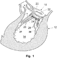
Fig. 1 , a portion of theheart 12 is illustrated. The portion comprises themitral valve 18, and theleft ventricle 14. The mitral valve is at its boundary circumferenced by anannulus 20. The valve has two cusps orleaflets leaflets papillary muscle chordae opposing leaflets Fig. 2 illustrates amitral valve 18, in which theleaflets annulus 20 becomes dilated. One surgical procedure to correct this is to remove a portion of theleaflet 24 and stitch the cut edges together with one another. The procedure will pull back theannulus 20 to a more normal position. However the strength of theleaflet 24 is altered. Similar problems with a less effective heart function may occur if one or bothleaflets - In some conditions of degenerated heart function, the
leaflets - Another possibility is that the leaflet is ruptured, most commonly at an edge of a leaflet, resulting in an incomplete coaptation. In some conditions of degenerated heart function, the leaflets do not present a solid surface, e.g. degenerative valve disease. The leaflet could be perforated, with one or several holes, where the blood can flow backwards into the atrium. Another possibility is that the leaflet is ruptured, most commonly at an edge of a leaflet, resulting in an incomplete coaptation.
- Similar problems may arise in other native heart valves, such as in an aortic valve, in a pulmonic valve or in a tricuspid valve.
- Some or all of these deficiencies may be remedied by the insertion of a prosthetic heart valve. However, it may be difficult to fit the prosthetic heart valve tightly to the native heart valve and thus, there may be a back-flow or leakage between the annulus or other surrounding valve tissue and the prosthetic heart valve.
- Hence, an arrangement and/or a method for replacement or repair of a native heart valve, in which there is no paravalvular leakage or regurgitation between a prosthetic heart valve and the surrounding valve tissue, would be advantageous.
- Furthermore, for fastening of such a prosthetic heart valve, replacement flaps can be used. Such replacement flaps can be anchored at dysfunctional flaps of the native heart valve and thereby give radial supporting force to the prosthetic heart valve, which is therefore also anchored. There are some prior art in this field, e.g.
EP 1 994 913 A2 ;EP 1 469 797 Bl;EP 1 259 195 Bl;WO 2007/051620 Al;WO 2007/048529 Al;EP 1 980 220 Al;WO 01/64137 EP 1 255 510 B3 ; andUS 5,411,552 . -
WO2008/058940 discloses device for improving the function of a heart valve comprises a first loop-shaped support, which is configured to abut a first side of the heart valve, and a first flange unit being connected to said first loop- shaped support. The flange unit is configured to be arranged against said annulus when said first loopshaped support is abutting said heart valve. An artificial valve is also disclosed. - Accordingly, embodiments of the present disclosure preferably seek to mitigate, alleviate or eliminate one or more deficiencies, disadvantages or issues in the art, such as the above-identified, singly or in any combination by providing an arrangement, a loop-shaped support, a prosthetic heart valve and a method of repairing or replacing a native heart valve, according to the appended patent claims.
- According to aspects of the disclosure, an arrangement, a loop-shaped support, a prosthetic heart valve and a method of repairing or replacing a native heart valve are disclosed, whereby leakage or regurgitation between a prosthetic heart valve and the surrounding valve tissue is prevented.
- According to a first aspect of the disclosure, an arrangement for replacement or repair of a native heart valve is provided. The arrangement comprises a loop-shaped support; and a prosthetic heart valve. An outer segment of the loop-shaped support is positionable towards surrounding valve tissue of the native heart valve. Furthermore, an outer surface of the prosthetic heart valve is positionable towards an inner segment of the loop-shaped support. Thereby paravalvular leakage or regurgitation between the prosthetic heart valve and the surrounding valve tissue of the native heart valve is prevented. The native heart valve may be an aortic valve, a mitral valve, a pulmonic valve or a tricuspid valve. Thus, an atrioventricular valve prosthesis can be used for one or several of an aortic valve, a mitral valve, a pulmonic valve or a tricuspid valve.
- According to a second aspect of the disclosure, a loop-shaped support is provided. The loop-shaped support is intended to be used in an arrangement for replacement or repair of a native heart valve. It has an inner segment and an outer segment. The inner segment is positionable towards a prosthetic heart valve and the outer segment is positionable towards surrounding valve tissue of a native heart valve. Thereby paravalvular leakage or regurgitation between the prosthetic heart valve and the surrounding valve tissue is prevented.
- According to a third aspect of the disclosure, a prosthetic heart valve is provided. The prosthetic heart valve is intended to be used in an arrangement for replacement or repair of a native heart valve. The prosthetic heart valve has an outer surface being positionable towards an inner segment of a loop-shaped support. Thereby paravalvular leakage or regurgitation between the prosthetic heart valve and surrounding valve tissue is prevented.
- According to a fourth aspect of the disclosure, a method of repairing or replacing a native heart valve is provided. The method comprises positioning of a loop-shaped support at an annulus of a native heart valve. The loop-shaped support comprises an inner segment and an outer segment. The outer segment of the loop-shaped support is positioned towards the annulus or surrounding valve tissue. Thereafter, a prosthetic heart valve is advanced towards the loop-shaped support. The prosthetic heart valve can be advanced partly through the loop-shaped support. An outer surface of the prosthetic heart valve is positioned towards the inner segment of the loop-shaped support. Thereby, paravalvular leakage or regurgitation between the prosthetic heart valve and the annulus and/or the surrounding valve tissue of the native heart valve is prevented.
- Further embodiments of the disclosure are defined in the dependent claims, wherein features for the second and subsequent aspects of the disclosure are as for the first aspect mutatis mutandis.
- Some embodiments of the disclosure provide for replacement or repair of a native heart valve.
- Some embodiments of the disclosure provide for prevention of paravalvular leakage or regurgitation between the prosthetic heart valve and the surrounding valve tissue of the native heart valve.
- Some embodiments of the disclosure also provide for sealing of the area between the prosthetic heart valve and the loop-shaped support to further improve prevention of paravalvular leakage or regurgitation.
- Some embodiments of the disclosure also provide for that both the area between the surrounding valve tissue and the flange unit/loop-shaped support and the area between the prosthetic heart valve and the flange unit/loop-shaped support are sealed.
- Some embodiments of the disclosure also provide for fixation of the loop-shaped support and/or the prosthetic heart valve.
- Some embodiments of the disclosure also provide for improved stability.
- Some embodiments of the disclosure also provide for prevention of unwanted loop-shaped support and prosthetic heart valve movement.
- Some embodiments of the disclosure also provide for that valve tissue will be trapped between the supports to fixate a desired shape of the valve.
- Some embodiments of the disclosure also facilitate delivery of a prosthetic heart valve.
- Some embodiments of the disclosure also provide for enabling minimally invasive and percutaneous replacement or repair of cardiac valves.
- It should be emphasized that the term "comprises/comprising" when used in this specification is taken to specify the presence of stated features, integers, steps or components but does not preclude the presence or addition of one or more other features, integers, steps, components or groups thereof.
- These and other aspects, features and advantages of which embodiments of the disclosure are capable of will be apparent and elucidated from the following description of embodiments of the present disclosure, reference being made to the accompanying drawings, in which
-
Fig. 1 is a cross-sectional view of the left ventricle of the heart; -
Fig. 2 is a lateral view of the mitral valve; -
Fig. 3a is a top view of a loop-shaped support; -
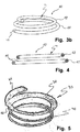
Fig. 3b is a lateral view of a helically shaped and loop-shaped support; -
Fig. 4 is a cross-sectional view of the loop-shapedsupport 41; -
Fig. 5 is a lateral view of a loop-shaped support with a flange unit; -
Fig. 6 is a lateral view of a stented prosthetic heart valve; -
Fig. 7 is a lateral view of a stented prosthetic heart valve positioned inside a loop-shaped support; -
Fig. 8 is a lateral view of a loop-shaped support positioned at the target site before the stented prosthetic heart valve has been positioned inside the loop-shaped support; and -
Fig. 9 is a view from above at an angle of a loop-shaped support equipped with fingers. - Specific embodiments of the disclosure will now be described with reference to the accompanying drawings. This disclosure may, however, be embodied in many different forms and should not be construed as limited to the embodiments set forth herein; rather, these embodiments are provided so that this disclosure will be thorough and complete, and will fully convey the scope of the invention to those skilled in the art. The terminology used in the detailed description of the embodiments illustrated in the accompanying drawings is not intended to be limiting of the disclosure. In the drawings, like numbers refer to like elements.
- The following description focuses on an embodiment of the present disclosure applicable to a native heart valve and in particular to a mitral valve. However, it will be appreciated that the disclosure is not limited to this application but may be applied to many other heart valves including for example an aortic valve, a pulmonic valve or a tricuspid valve.
- In an embodiment of the disclosure according to
Fig. 3a , the loop-shapedsupport 41 is round and forms a circle. The loop-shapedsupport 41 has anouter segment 32 and aninner segment 34. Theouter segment 32 may on the outer edge of the loop-shapedsupport 41 be threaded so as to provide a possibility to better fixate the loop-shaped support to the surrounding valve tissue and thus prevent the loop-shaped support from sliding out of its position. As can be seen fromfig. 3a , the loop-shapedsupport 41 has atop portion 36 located between theouter segment 32 and theinner segment 34. On the opposite side of the top portion, there is a bottom portion (not seen in the figure). - Another loop-shaped
support 41 according to one embodiment of the present disclosure is shown inFigs. 3b and 4 . The loop-shapedsupport 41 comprises a first and asecond section - As used herein, the term "loop-shaped" should be construed as a curved shape that may be closed, as at least a part of a ring with e.g. a circular, elliptic, or D-shaped form or any other closed form which may fit the shape of the valve annulus. The term "loop-shaped" also includes a curved shape that is open forming an arcuate shape, such as a C-shape or U-shape, which includes an angular turn of at least 180° such that the support may abut valve tissue along a major part of the annular valve shape. The term "loop-shaped" also includes a curved shape overlapping itself to form a portion of a coil or helical structure. Such a helical structure may comprise a first part to be placed on the atrial side of the native heart valve and a second part to be placed on the ventricular side of the native heart valve. The first part may have a diameter, which is larger then a diameter of the second part. A helical loop-shaped support or helical support rings may also be used for anchoring of occlusion devices, such as occluders for closing atrial septal defects.
- The term "loop-shaped" also includes three dimensional curves.
- The loop shape of at least a part of at least one of the
sections - In
US 6,419,696 ,US 6,730,121 ,US 6,964,684 , andWO 2006/091163 , which are assigned to the same applicant as the present disclosure and incorporated by reference herein in their entirety for all purposes, devices are disclosed for repairing and replacing a heart valve in various embodiments. The devices include at least first and second support rings connected together in loop-shaped configurations to abut opposite sides of a valve annulus. A replacement valve may be secured to the loop-shaped devices. - The
first section 42 may be continuous and/or integral with thesecond section 44 such that thesections - The
second section 44 may have an outer boundary or extent which is greater in relation to the outer boundary of thefirst section 42. Thesections second section 44 being in larger scale than thefirst section 42. This is advantageous for creating a pinch of the valve tissue between the first 42 andsecond sections 44. - An
end 45 of thesecond section 44, which will lead the coil during insertion of the device at the valve, may in an embodiment have a greater pitch than the rest of the coil. This implies that the leadingend 45 of the coil during rotation into position in the valve will project from immediate contact with the valve tissue and, therefore, the risk that the coil is caught by the chords is diminished. - The loop-shaped
support 41 is shown in cross-section inFig. 4 . The loop-shapedsupport 41 has in an embodiment at least partly a round cross-sectional shape. In other embodiments, the cross-section of the loop-shapedsupport 41 may be substantially flat, oval, flattened and/or have flattened edges. As an example, the loop-shapedsupport 41 may in one embodiment have anouter segment 32, which is substantially round or rounded and aninner segment 34, which is substantially flat or flattened. A better fit to a prosthetic heart valve may be provided by the use of a flat or flattenedinner segment 34. Thereby, the sealing of the area between the prosthetic heart valve and the loop-shaped support and the prevention of paravalvular leakage is further improved. - In embodiments, the
opposed surfaces 46 thus provide a pinch to trap valve tissue there between. A round cross-section is also advantageous in creating a pinch of the valve tissue which will not harm the leaflets in their movement during normal heart action. - The
second section 44 is slightly displaced radially with respect to thefirst section 42. This implies that the first andsecond sections second sections 44 is therefore not sharply defined in a radial direction of the valve. This implies that a pinching force between thesections - The
sections first section 42 has a diameter corresponding to a line through the centre of thesecond section 44. Thus, thesections - Further, the cross-section of the
sections - The loop-shaped
support 41 may be formed from a core of a rigid material, such as a metal, e.g. titanium, or plastic. The rigid material may provide a passive spring function, so that the loops of the coil may be forced a small distance away from each other but will flex back towards each other when the force is released. The core of the loop-shapedsupport 41 may be coated by a softer layer, such as a textile. - The loop-shaped
support 41 may alternatively be formed from a shape memory material. The loop-shapedsupport 41 will then assume a desired, programmed shape, when e.g. heated to a specific temperature. This allows the loop-shapedsupport 41 to be compressed or straightened to a form better suited for deliverance and/or during insertion and to assume a spiral or helical shape when inserted at the heart valve. Also aflange unit 50 may be made of such a shape memory material, e.g. to provide a first, delivery shape and a second shape assumed after being delivered. - Now turning to
Fig. 5 , an embodiment of the loop-shapedsupport 41 is disclosed. The loop-shapedsupport 41 comprises aflange unit 50 being connected to thefirst section 42. Theflange unit 50 has in an embodiment a continuous extension along the periphery of thefirst section 42. - In some embodiments, the
flange unit 50 may be integral with at least a portion of the loop-shapedsupport 41. - In some embodiments the
flange unit 50 is made of a tube shaped flexible material being passed onto thefirst section 42, whereby a loose substantially co-axial connection between the loop-shapedsupport 41 and theflange unit 50 is achieved. The connection may also be fixed or rigid. The flexible material may by way of example be a fabric or woven structure made of Polyethylene (PE) or polytetrafluoroethylene (PTFE). A fabric has the advantage that it presents a rough, holed or porous surface enhancing growth of and overgrowth of endothelia. Further, a fabric is easily penetrated by sutures or clips. In addition, the flexible material admits theflange unit 50 to be conformed to the annulus. It also admits theflange unit 50 to be conformed to aprosthetic heart valve 70. - The
flange unit 50 does in the disclosed embodiment form a flange surface extending downwards out from the body. More precisely theflange unit 50 forms in some embodiments an angle α to a horizontal, diametric plane formed by the loop-shaped support. The angle α is approximately between 30-60°, such as 40-50° to the diametric plane. Such angle improves the visibility during insertion of the loop-shaped support. In some embodiments, improved visibility may be provided during insertion of the loop-shaped support, whereupon theflange unit 50 changes shape to a position facilitating fixation thereof to surrounding tissue. Thus, medical procedures for heart valve repair and/or replacement may be speeded up considerably. - In a practical embodiment the flange surface has a width in the range of approximately 2-4 mm, such as 2.5-3.5 mm. The width of the flange radially outwards allows an indication for the surgeon of the area in which sutures or clips should be positioned when fixating the loop-shaped support to the annulus. Initially, before inserted into the heart valve, the flange surface extends downwardly. When positioned in the atrial side of the heart valve, the loop-shaped
support 41 will be arranged abutting the annulus, whereby theflange unit 50 will be conformed to the annulus, changing its angle from extending downwardly to extending upwardly. This ability to conform is a combination of the flexibility of the (fabric) material and the width of theflange unit 50. - On its outer periphery, the
flange unit 50 may comprise a reinforcingelement 65, which is schematically illustrated inFig. 5 . Such reinforcing element may by way of example have the form of a thread or a bead. - In an embodiment according to
fig. 6 , aprosthetic heart valve 70 comprises a stent orstent frame 52 and avalve structure 54. Thestent frame 52 is generally constructed so as to be self-expandable from a compressed arrangement to the normal, expanded arrangement (shown inFig. 6 ). In other embodiments, thestent frame 52 is expandable to the expanded arrangement by a separate device, e.g., a balloon internally located within thestent frame 52. Thevalve structure 54 is assembled to thestent frame 52 and provides two ormore leaflets 56. Theprosthetic heart valve 70 may also be fastened as described in e.g.US5411552 A orEP1255510 B. As an example, a mitral valve or a tricuspid valve from e.g. a pig can be fastened to the loop-shaped support by sewing. Theprosthetic heart valve 70 is configured for replacing or repairing a native mitral valve. Alternatively, other shapes are also envisioned, adapted to the specific anatomy of the valve to be repaired, e.g., stented prosthetic heart valves in accordance with the present disclosure can be shaped and/or sized for replacing a native aortic, pulmonic, or tricuspid valve. In one embodiment, thevalve structure 54 extends less than the entire length of thestent frame 52, but in other embodiments it can extend along an entirety, or a near entirety, of a length of thestent frame 52. A wide variety of other constructions are also acceptable and within the scope of the present disclosure. For example, thestent frame 52 can have a more cylindrical shape in the normal, expanded arrangement. - A further embodiment of the disclosure is illustrated in
Fig. 7 . Infig. 7 , theprosthetic heart valve 70 is shown in an arrangement for replacement or repair of a native heart valve, together with a loop-shapedsupport 41. Anouter segment 32 of the loop-shapedsupport 41 is positionable towards surrounding valve tissue of a native heart valve. Furthermore, as can be seen from the figure, anouter surface 74 of theprosthetic heart valve 70 is positionable towards aninner segment 34 of the loop-shapedsupport 41 so as to prevent paravalvular leakage or regurgitation between theprosthetic heart valve 70 and the surrounding valve tissue of the native heart valve. Theinner segment 34 is adapted for receiving a radially expandableprosthetic heart valve 70, and the loop-shapedsupport 41 is radially rigid, i.e. rigid in a radial direction, for preventing an expansion of theprosthetic heart valve 70 beyond theinner segment 34. However, the expandableprosthetic heart valve 70 will expand as far as it can in order to reach its normal expanded state, when it is expanded during delivery. Thus, theouter surface 74 of theprosthetic heart valve 70 will be tightly positioned towards aninner segment 34 of the loop-shapedsupport 41. Thereby the area between theprosthetic heart valve 70 and the loop-shapedsupport 41 is sealed. Infig. 7 , the loop-shapedsupport 41 is depicted as a round circle-shaped support. However, in other embodiments, the loop-shapedsupport 41 may be helically or coil-shaped as depicted infigures 3b-5 . - Since the
flange unit 50 provides for a sealing surface against the annulus allowing prevention of backflow of blood from the ventricle to the atrial side, both the area between the surrounding valve tissue and theflange unit 50/loop-shapedsupport 41 and the area between theprosthetic heart valve 70 and theflange unit 50/loop-shapedsupport 41 are sealed. Theflange unit 50 may also form a flange surface on both sides of the annulus or heart valve, which surface may provide for fixation of loop-shapedsupport 41 and/orprosthetic heart valve 70. -
Fig. 8 shows a loop-shapedsupport 41 positioned at the target site before the stentedprosthetic heart valve 70 has been positioned inside the loop-shapedsupport 41. In this embodiment, the target site is a native heart valve, such as amitral valve 18 and the loop-shapedsupport 41 is helically shaped. Alsonative leaflets valve tissue 80 can be seen in the figure. The first andsecond sections second section 44 has been rotated or screwed through the valve into its position. If needed, the loop-shapedsupport 41 may be further secured to the valve by clips, sutures or other suitable means. - In one embodiment, one of the sections, e.g. the
first section 42 extends further away from the native heart valve than the other section, e.g. thesecond section 44, so as to provide a larger sealing area towards theprosthetic heart valve 70. Normally the loop-shapedsupport 41 is positioned at the target site first and first thereafter theprosthetic heart valve 70 is positioned at the target site. However, it is also possible that theprosthetic heart valve 70 is positioned at the target site before introduction of the loop-shapedsupport 41. When the loop-shapedsupport 41 has been positioned at the target site, the stentedprosthetic heart valve 70 is fitted to the loop-shapedsupport 41 by first positioning the stentedprosthetic heart valve 70 inside the loop-shapedsupport 41 and then expanding the stentedprosthetic heart valve 70 to its normal expanded state. Thus, the area between theprosthetic heart valve 70 and the loop-shapedsupport 41 is sealed. Thereby paravalvular leakage or regurgitation between theprosthetic heart valve 50 and surrounding valve tissue is prevented. - A further embodiment is depicted in
figure 9 . Instead or in addition to having a section extending further away from the native heart valve, the loop-shapedsupport 41 may havefingers 90, extensions, crown-shaped extensions or struts connected to atop portion 36 or a bottom portion of the loop-shapedsupport 41 and pointing in a direction away from the native heart valve when the loop-shapedsupport 41 has been placed in its operational position, which direction is substantially parallel with a longitudinal centre axis of the loop-shapedsupport 41. These fingers may support the positioning of a prosthetic heart valve inside the loop-shapedsupport 41 and eliminate or reduce tilting movement in relation to a plane being in parallel with a mitral plane, i.e. a plane having the atrium on one side and the ventricle on the other side. Thefingers 90 may be slightly flexible so that they can better adapt to the shape of a prosthetic heart valve. As an alternative, the loop-shapedsupport 41 may havefingers 90 extending in both directions pointing away from the native heart valve, i.e. in a direction from the native heart valve towards the atrium and in a direction from the native heart valve towards the ventricle, when the loop-shaped support has been placed in its operational position. By the use offingers 90 in both directions, the positioning of a prosthetic heart valve inside the loop-shaped support may be further supported and thus, a tilting movement may be further reduced. In one embodiment, the loop-shapedsupport 41 has atop portion 36 and a bottom portion. At least one of the top 36 and bottom portions is connected to at least one crown-shaped portion and a top of the at least one crown-shaped portion is extending substantially perpendicularly towards the atrium or the ventricle so that the positioning of a prosthetic heart valve inside the loop-shapedsupport 41 is supported by the at least one crown-shaped portion. A tilting movement in relation to a plane being in parallel with a mitral plane may also be eliminated or reduced. - In some embodiments the prosthetic heart valve (70) is rigid. The outer surface (74) of the prosthetic heart valve (70) is tightly positioned towards the inner segment (34) of the loop-shaped support (41), so as to seal the area between the prosthetic heart valve (70) and the loop-shaped support (41). The loop-shaped support (41) is in these embodiments somewhat flexible to compensate for the rigidity of the prosthetic heart valve (70).
- In some embodiments a circumference of the loop-shaped support (41) is substantially larger than a circumference of the prosthetic heart valve (70). The loop-shaped support (41) is then radially downsizeable to fit tightly around the prosthetic heart valve (70) so as to seal the area between the prosthetic heart valve (70) and the loop-shaped support (41). The loop-shaped support, which has a circumference which is substantially larger than the circumference of the prosthetic heart valve (70) may be downsizeable, e.g. by first assuming a first shape and then after positioning assuming a second shape, which may be obtained by a change of shape, such as a change of shape of a shape memory material. By such a change in shape, i.e. a change from oversized to a size that is just right, the loop-shaped support (41) may fit tightly around the prosthetic heart valve (70) so as to seal the area between the prosthetic heart valve (70) and the loop-shaped support (41).Another situation when valve leakage, i.e. regurgitation or valvular insufficiency may occur is during catheter-based delivery. During delivery through a catheter, e.g. for replacement or repair of cardiac valves, such as the mitral valve, there is a chance that the catheter delivered valve may cause leakage or regurgitation, since the surrounding tissue is non-rigid. The soft tissue in the annulus region is thus not tightly holding the valve in its desired place. The surrounding soft tissue may over extend and due to increasing blood pressure during the heart cycle, an outer by-pass blood flow may occur at the outer circumference of the valve or its casing or anchoring stent. In such a situation, a loop-shaped
support 41 may be beneficial for preventing paravalvular leakage or regurgitation. - In some embodiments, the
fingers 90 are slightly offset from the loop-shaped support (41) in a radial direction, so that there is a gap between theouter segment 32 of the loop-shapedsupport 41 and thefingers 90. Thefingers 90 may then be attached to only a portion of the full axial length of the loop-shapedsupport 41 so that a gap is formed between the loop-shaped support and thefingers 90 for a part of the loop-shaped support in an axial direction. In one embodiment, the fingers are attached to the loop-shaped support for at least half of the full axial length of the loop-shapedsupport 41. By the use offingers 90, which are located slightly offset from the loop-shaped support, biological material, e.g. natural remaining valvular tissue from the native heart valve, such as dysfunctional flaps and/or chordaes, can be trapped in the gap between the loop-shapedsupport 41 and thefingers 90. Thereby, the positioning of the loop-shapedsupport 41 and/or theprosthetic heart valve 70 is further stabilized and therefore paravalvular leakage is further prevented. - Also when metal is put against metal at a target site, such as at a mitral valve, there is no good adherence. Thus, there is a possibility of leakage or regurgitation between two metal parts, especially between two round or cylinder-formed metal parts or when one metal part is to be positioned inside another metal part. In one embodiment, a loop-shaped
support 41 may be positioned in-between the metal parts at a target site, such as the mitral valve, so as to provide good adherence and to seal the area between the two metal parts, so that no leakage will occur at the target valve. - The arrangement, the loop-shaped support and/or the prosthetic heart valve can be implanted via a catheter. This may be performed transepitally, transapically or transvascularly, e.g retroversily via the aorta.
- Furthermore, other means, such as hooks, can be used for anchoring of the arrangement, the loop-shaped support and/or the prosthetic heart valve.In one example, the
prosthetic heart valve 70 is anchored with anchor elements. Thus, a method of anchoring aprosthetic heart valve 70 in a patient's heart is provided. The method comprises anchoring theprosthetic heart valve 70 on the ventricular side with three or more, preferably four, anchor elements integrated with theprosthetic heart valve 70 situated on the ventricle side of theprosthetic heart valve 70, extending outwards from theprosthetic heart valve 70 and distributed equally around theprosthetic heart valve 70. The method further comprises anchoring theprosthetic heart valve 70 on the atrial side with three or more, preferably four, anchor elements integrated with theprosthetic heart valve 70 situated on the atrium side of theprosthetic heart valve 70, extending outwards from theprosthetic heart valve 70 and distributed equally around theprosthetic heart valve 70. By the use of this method, theprosthetic heart valve 70 is further stabilized in its position at the target site. - The present disclosure has been described above with reference to specific embodiments. The scope of the disclosure is only limited by the appended patent claims. More generally, those skilled in the art will readily appreciate that all parameters, dimensions, materials, and configurations described herein are meant to be exemplary and that the actual parameters, dimensions, materials, and/or configurations will depend upon the specific application or applications for which the teachings of the present disclosure is/are used.
Claims (9)
- A loop-shaped support for use in an arrangement for replacement or repair of a native heart valve, having an inner segment (34) and an outer segment (32), and wherein said inner segment (34) is positionable towards a prosthetic heart valve (70) and said outer segment (32) is positionable towards surrounding valve tissue of a native heart valve so that paravalvular leakage or regurgitation between said prosthetic heart valve (70) and said surrounding valve tissue is prevented,
wherein said inner segment (34) is adapted for receiving a radially expandable prosthetic heart valve (70), and wherein said loop-shaped support (41) is radially rigid for preventing an expansion of said prosthetic heart valve (70) beyond said inner segment (34),
characterized in that
the loop-shaped support (41) comprises extensions (90) for supporting the positioning of said prosthetic heart valve (70) inside the loop-shaped support (41), wherein, when in use, said extensions (90) are pointing in a direction away from the native heart valve. - The loop-shaped support of claim 1, wherein said surrounding valve tissue comprises an annulus (20), and wherein said arrangement further comprises a flange unit (50), said flange unit (50) being connected to said loop-shaped support (41), and which flange unit (50) is configured to be arranged against said annulus (20) for attaching said flange unit (50) and said loop-shaped support (41) to said annulus (20) and wherein said flange unit (50) is of a fabric material.
- The loop-shaped support of any of claims 1-2, wherein said loop-shaped support (41) is helically shaped and/or screwable into said annulus (20) for improved stability.
- An arrangement for replacement or repair of a native heart valve, comprising:the loop-shaped support (41) according to any one of claims 1-3; anda radially expandable prosthetic heart valve (70).
- The arrangement of claim 4, wherein said prosthetic heart valve (70) is rigid and wherein said outer surface (74) of said prosthetic heart valve (70) is tightly positioned towards said inner segment (34) of said loop-shaped support (41) so as to seal the area between said prosthetic heart valve (70) and said loop-shaped support (41).
- The arrangement of claim 4, wherein a circumference of said loop-shaped support (41) is substantially larger than a circumference of said prosthetic heart valve (70) and wherein said loop-shaped support (41) is radially downsizeable to fit tightly around said prosthetic heart valve (70) so as to seal the area between said prosthetic heart valve (70) and said loop-shaped support (41).
- The arrangement of any of claims 4 or 6, wherein said prosthetic heart valve (70) is a stented prosthetic heart valve.
- The arrangement of claim 7, wherein said surrounding valve tissue comprises an annulus (20), and wherein said arrangement further comprises a flange unit (50), said flange unit (50) being connected to said loop-shaped support (41), and which flange unit (50) is configured to be arranged against said annulus (20) for attaching said flange unit (50) and said loop-shaped support (41) to said annulus (20) and wherein said flange unit (50) is of a fabric material.
- The arrangement of any of claims 7-8, wherein said loop-shaped support (41) is helically shaped and/or screwable into said annulus (20) for improved stability.
Priority Applications (12)
| Application Number | Priority Date | Filing Date | Title |
|---|---|---|---|
| EP12152348.4A EP2620125B1 (en) | 2012-01-24 | 2012-01-24 | An arrangement, a loop-shaped support, a prosthetic heart valve and a method of repairing or replacing a native heart valve |
| CA2861416A CA2861416C (en) | 2012-01-24 | 2013-01-24 | An arrangement, a loop-shaped support, a prosthetic heart valve and a method of repairing or replacing a native heart valve |
| US14/373,878 US9474599B2 (en) | 2012-01-24 | 2013-01-24 | Arrangement, a loop-shaped support, a prosthetic heart valve and a method of repairing or replacing a native heart valve |
| CA2976233A CA2976233C (en) | 2012-01-24 | 2013-01-24 | An arrangement, a loop-shaped support, a prosthetic heart valve and a method of repairing or replacing a native heart valve |
| PCT/EP2013/051366 WO2013110722A2 (en) | 2012-01-24 | 2013-01-24 | An arrangement, a loop-shaped support, a prosthetic heart valve and a method of repairing or replacing a native heart valve |
| EP13701096.3A EP2806829B1 (en) | 2012-01-24 | 2013-01-24 | An arrangement, a loop-shaped support, a prosthetic heart valve and a method of repairing or replacing a native heart valve |
| JP2014552665A JP5980955B2 (en) | 2012-01-24 | 2013-01-24 | Structure for repairing or replacing a native heart valve, loop shaped support, prosthetic heart valve and method |
| CN201380006306.1A CN104220028B (en) | 2012-01-24 | 2013-01-24 | A kind of device, annular support and prosthetic heart valve |
| US15/275,903 US10321989B2 (en) | 2012-01-24 | 2016-09-26 | Arrangement, a loop-shaped support, a prosthetic heart valve and a method of repairing or replacing a native heart valve |
| US16/405,286 US20190262130A1 (en) | 2012-01-24 | 2019-05-07 | Arrangement, A Loop-Shaped Support, A Prosthetic Heart Valve And A Method Of Repairing Or Replacing A Native Heart Valve |
| US17/246,685 US11504230B2 (en) | 2012-01-24 | 2021-05-02 | Arrangement, a loop-shaped support, a prosthetic heart valve and a method of repairing or replacing a native heart valve |
| US17/246,683 US11839538B2 (en) | 2012-01-24 | 2021-05-02 | Arrangement, a loop-shaped support, a prosthetic heart valve and a method of repairing or replacing a native heart valve |
Applications Claiming Priority (1)
| Application Number | Priority Date | Filing Date | Title |
|---|---|---|---|
| EP12152348.4A EP2620125B1 (en) | 2012-01-24 | 2012-01-24 | An arrangement, a loop-shaped support, a prosthetic heart valve and a method of repairing or replacing a native heart valve |
Publications (2)
| Publication Number | Publication Date |
|---|---|
| EP2620125A1 EP2620125A1 (en) | 2013-07-31 |
| EP2620125B1 true EP2620125B1 (en) | 2017-10-11 |
Family
ID=45509346
Family Applications (2)
| Application Number | Title | Priority Date | Filing Date |
|---|---|---|---|
| EP12152348.4A Active EP2620125B1 (en) | 2012-01-24 | 2012-01-24 | An arrangement, a loop-shaped support, a prosthetic heart valve and a method of repairing or replacing a native heart valve |
| EP13701096.3A Revoked EP2806829B1 (en) | 2012-01-24 | 2013-01-24 | An arrangement, a loop-shaped support, a prosthetic heart valve and a method of repairing or replacing a native heart valve |
Family Applications After (1)
| Application Number | Title | Priority Date | Filing Date |
|---|---|---|---|
| EP13701096.3A Revoked EP2806829B1 (en) | 2012-01-24 | 2013-01-24 | An arrangement, a loop-shaped support, a prosthetic heart valve and a method of repairing or replacing a native heart valve |
Country Status (6)
| Country | Link |
|---|---|
| US (5) | US9474599B2 (en) |
| EP (2) | EP2620125B1 (en) |
| JP (1) | JP5980955B2 (en) |
| CN (1) | CN104220028B (en) |
| CA (2) | CA2861416C (en) |
| WO (1) | WO2013110722A2 (en) |
Cited By (13)
| Publication number | Priority date | Publication date | Assignee | Title |
|---|---|---|---|---|
| US10856984B2 (en) | 2017-08-25 | 2020-12-08 | Neovasc Tiara Inc. | Sequentially deployed transcatheter mitral valve prosthesis |
| US10940001B2 (en) | 2012-05-30 | 2021-03-09 | Neovasc Tiara Inc. | Methods and apparatus for loading a prosthesis onto a delivery system |
| US11311376B2 (en) | 2019-06-20 | 2022-04-26 | Neovase Tiara Inc. | Low profile prosthetic mitral valve |
| US11357622B2 (en) | 2016-01-29 | 2022-06-14 | Neovase Tiara Inc. | Prosthetic valve for avoiding obstruction of outflow |
| US11389291B2 (en) | 2013-04-04 | 2022-07-19 | Neovase Tiara Inc. | Methods and apparatus for delivering a prosthetic valve to a beating heart |
| US11413139B2 (en) | 2011-11-23 | 2022-08-16 | Neovasc Tiara Inc. | Sequentially deployed transcatheter mitral valve prosthesis |
| US11419720B2 (en) | 2010-05-05 | 2022-08-23 | Neovasc Tiara Inc. | Transcatheter mitral valve prosthesis |
| US11464631B2 (en) | 2016-11-21 | 2022-10-11 | Neovasc Tiara Inc. | Methods and systems for rapid retraction of a transcatheter heart valve delivery system |
| US11491006B2 (en) | 2019-04-10 | 2022-11-08 | Neovasc Tiara Inc. | Prosthetic valve with natural blood flow |
| US11497602B2 (en) | 2012-02-14 | 2022-11-15 | Neovasc Tiara Inc. | Methods and apparatus for engaging a valve prosthesis with tissue |
| US11602429B2 (en) | 2019-04-01 | 2023-03-14 | Neovasc Tiara Inc. | Controllably deployable prosthetic valve |
| US11737872B2 (en) | 2018-11-08 | 2023-08-29 | Neovasc Tiara Inc. | Ventricular deployment of a transcatheter mitral valve prosthesis |
| US11779742B2 (en) | 2019-05-20 | 2023-10-10 | Neovasc Tiara Inc. | Introducer with hemostasis mechanism |
Families Citing this family (78)
| Publication number | Priority date | Publication date | Assignee | Title |
|---|---|---|---|---|
| EP2572676B1 (en) | 2007-09-26 | 2016-04-13 | St. Jude Medical, Inc. | Collapsible prosthetic heart valves |
| US9532868B2 (en) | 2007-09-28 | 2017-01-03 | St. Jude Medical, Inc. | Collapsible-expandable prosthetic heart valves with structures for clamping native tissue |
| US8323335B2 (en) | 2008-06-20 | 2012-12-04 | Edwards Lifesciences Corporation | Retaining mechanisms for prosthetic valves and methods for using |
| JP5379852B2 (en) | 2008-07-15 | 2013-12-25 | セント ジュード メディカル インコーポレイテッド | Collapsible and re-expandable prosthetic heart valve cuff design and complementary technology application |
| WO2010117680A1 (en) | 2009-03-30 | 2010-10-14 | Cardiovantage Medical, Inc. | Sutureless valve prostheses and devices and methods for delivery |
| US8870950B2 (en) | 2009-12-08 | 2014-10-28 | Mitral Tech Ltd. | Rotation-based anchoring of an implant |
| HUE059497T2 (en) | 2010-03-05 | 2022-11-28 | Edwards Lifesciences Corp | Retaining mechanisms for prosthetic valves |
| WO2011111047A2 (en) | 2010-03-10 | 2011-09-15 | Mitraltech Ltd. | Prosthetic mitral valve with tissue anchors |
| US8657872B2 (en) | 2010-07-19 | 2014-02-25 | Jacques Seguin | Cardiac valve repair system and methods of use |
| US9763657B2 (en) | 2010-07-21 | 2017-09-19 | Mitraltech Ltd. | Techniques for percutaneous mitral valve replacement and sealing |
| US11653910B2 (en) | 2010-07-21 | 2023-05-23 | Cardiovalve Ltd. | Helical anchor implantation |
| WO2012012761A2 (en) | 2010-07-23 | 2012-01-26 | Edwards Lifesciences Corporation | Retaining mechanisms for prosthetic valves |
| CN111265339B (en) | 2010-10-05 | 2022-03-01 | 爱德华兹生命科学公司 | Artificial heart valve |
| EP2739214B1 (en) | 2011-08-05 | 2018-10-10 | Cardiovalve Ltd | Percutaneous mitral valve replacement and sealing |
| US8852272B2 (en) | 2011-08-05 | 2014-10-07 | Mitraltech Ltd. | Techniques for percutaneous mitral valve replacement and sealing |
| WO2013021374A2 (en) | 2011-08-05 | 2013-02-14 | Mitraltech Ltd. | Techniques for percutaneous mitral valve replacement and sealing |
| US9387075B2 (en) * | 2011-09-12 | 2016-07-12 | Highlife Sas | Transcatheter valve prosthesis |
| US9078747B2 (en) | 2011-12-21 | 2015-07-14 | Edwards Lifesciences Corporation | Anchoring device for replacing or repairing a heart valve |
| CN104220027B (en) | 2012-01-31 | 2017-11-07 | 米特拉尔维尔福科技有限责任公司 | Bicuspid valve parking device, system and method |
| ES2934670T3 (en) | 2013-01-24 | 2023-02-23 | Cardiovalve Ltd | Ventricularly Anchored Prosthetic Valves |
| JP2016512077A (en) | 2013-03-14 | 2016-04-25 | カーディオヴァンテージ・メディカル・インク | Embolization protection device and method of use |
| US11259923B2 (en) | 2013-03-14 | 2022-03-01 | Jc Medical, Inc. | Methods and devices for delivery of a prosthetic valve |
| US11406497B2 (en) | 2013-03-14 | 2022-08-09 | Jc Medical, Inc. | Heart valve prosthesis |
| BR112016002887B1 (en) | 2013-08-12 | 2021-05-25 | Mitral Valve Technologies Sarl | system for replacing a native heart valve |
| ES2864087T3 (en) | 2013-08-14 | 2021-10-13 | Mitral Valve Tech Sarl | Replacement heart valve appliance |
| US10195028B2 (en) | 2013-09-10 | 2019-02-05 | Edwards Lifesciences Corporation | Magnetic retaining mechanisms for prosthetic valves |
| WO2015057995A2 (en) | 2013-10-16 | 2015-04-23 | Cedars-Sinai Medical Center | Modular dis-assembly of transcatheter valve replacement devices and uses thereof |
| WO2015058001A1 (en) | 2013-10-17 | 2015-04-23 | Cedars-Sinai Medical Center | Device to percutaneously treat heart valve embolization |
| US9913715B2 (en) | 2013-11-06 | 2018-03-13 | St. Jude Medical, Cardiology Division, Inc. | Paravalvular leak sealing mechanism |
| US9622863B2 (en) | 2013-11-22 | 2017-04-18 | Edwards Lifesciences Corporation | Aortic insufficiency repair device and method |
| EP4186473A1 (en) | 2013-12-11 | 2023-05-31 | Cedars-Sinai Medical Center | Methods, devices and systems for transcatheter mitral valve replacement in a double-orifice mitral valve |
| EP3099345B1 (en) | 2014-01-31 | 2018-10-10 | Cedars-Sinai Medical Center | Pigtail for optimal aortic valvular complex imaging and alignment |
| EP3102152B1 (en) | 2014-02-04 | 2019-08-21 | Innovheart S.r.l. | Prosthetic device for a heart valve |
| EP2907479A1 (en) * | 2014-02-18 | 2015-08-19 | Medtentia International Ltd Oy | A system and a method for delivery of an annuloplasty implant |
| CN106572905B (en) | 2014-02-20 | 2019-11-05 | 米特拉尔维尔福科技有限责任公司 | It is used to support the anchoring piece curled up, heart valve prosthesis and deployment device of heart valve prosthesis |
| CA2937849C (en) | 2014-02-21 | 2023-04-11 | Mitral Valve Technologies Sarl | Devices, systems and methods for delivering a prosthetic mitral valve and anchoring device |
| US10524910B2 (en) | 2014-07-30 | 2020-01-07 | Mitraltech Ltd. 3 Ariel Sharon Avenue | Articulatable prosthetic valve |
| US10016272B2 (en) | 2014-09-12 | 2018-07-10 | Mitral Valve Technologies Sarl | Mitral repair and replacement devices and methods |
| EP3253333B1 (en) | 2015-02-05 | 2024-04-03 | Cardiovalve Ltd | Prosthetic valve with axially-sliding frames |
| US10231834B2 (en) | 2015-02-09 | 2019-03-19 | Edwards Lifesciences Corporation | Low profile transseptal catheter and implant system for minimally invasive valve procedure |
| US10039637B2 (en) | 2015-02-11 | 2018-08-07 | Edwards Lifesciences Corporation | Heart valve docking devices and implanting methods |
| EP3267940A4 (en) * | 2015-03-12 | 2018-11-07 | Cedars-Sinai Medical Center | Devices, systems, and methods to optimize annular orientation of transcatheter valves |
| US11833034B2 (en) | 2016-01-13 | 2023-12-05 | Shifamed Holdings, Llc | Prosthetic cardiac valve devices, systems, and methods |
| EP3405139B1 (en) * | 2016-01-22 | 2020-10-07 | Medtentia International Ltd Oy | Annuloplasty implant |
| CN105726167A (en) * | 2016-02-02 | 2016-07-06 | 上海纽脉医疗科技有限公司 | Involved artificial heart valve prosthesis |
| US10363130B2 (en) | 2016-02-05 | 2019-07-30 | Edwards Lifesciences Corporation | Devices and systems for docking a heart valve |
| US10531866B2 (en) | 2016-02-16 | 2020-01-14 | Cardiovalve Ltd. | Techniques for providing a replacement valve and transseptal communication |
| KR101810057B1 (en) * | 2016-05-12 | 2017-12-18 | 주식회사 엠아이텍 | Stent for preventing tissue overgrowth caused by stimulation |
| US10828150B2 (en) | 2016-07-08 | 2020-11-10 | Edwards Lifesciences Corporation | Docking station for heart valve prosthesis |
| CN109789018B (en) | 2016-08-10 | 2022-04-26 | 卡迪尔维尔福股份有限公司 | Prosthetic valve with coaxial frame |
| US10828152B2 (en) * | 2016-08-11 | 2020-11-10 | 4C Medical Technologies, Inc. | Heart chamber prosthetic valve implant with base, spring and dome sections with single chamber anchoring for preservation, supplementation and/or replacement of native valve function |
| US10722359B2 (en) | 2016-08-26 | 2020-07-28 | Edwards Lifesciences Corporation | Heart valve docking devices and systems |
| CR20190069A (en) | 2016-08-26 | 2019-05-14 | Edwards Lifesciences Corp | Heart valve docking coils and systems |
| US10357361B2 (en) | 2016-09-15 | 2019-07-23 | Edwards Lifesciences Corporation | Heart valve pinch devices and delivery systems |
| FI3554424T3 (en) | 2016-12-16 | 2023-03-30 | Edwards Lifesciences Corp | Deployment systems and tools for delivering an anchoring device for a prosthetic valve |
| CN114617677A (en) | 2016-12-20 | 2022-06-14 | 爱德华兹生命科学公司 | System and mechanism for deploying a docking device for replacing a heart valve |
| US10813749B2 (en) | 2016-12-20 | 2020-10-27 | Edwards Lifesciences Corporation | Docking device made with 3D woven fabric |
| US11654023B2 (en) | 2017-01-23 | 2023-05-23 | Edwards Lifesciences Corporation | Covered prosthetic heart valve |
| US11185406B2 (en) | 2017-01-23 | 2021-11-30 | Edwards Lifesciences Corporation | Covered prosthetic heart valve |
| US11013600B2 (en) | 2017-01-23 | 2021-05-25 | Edwards Lifesciences Corporation | Covered prosthetic heart valve |
| USD867595S1 (en) | 2017-02-01 | 2019-11-19 | Edwards Lifesciences Corporation | Stent |
| ES2779850T3 (en) | 2017-04-28 | 2020-08-20 | Medtentia Int Ltd Oy | Annuloplasty implant |
| US10842619B2 (en) | 2017-05-12 | 2020-11-24 | Edwards Lifesciences Corporation | Prosthetic heart valve docking assembly |
| JP7277389B2 (en) | 2017-06-30 | 2023-05-18 | エドワーズ ライフサイエンシーズ コーポレイション | Docking station for transcatheter valves |
| AU2018291171B2 (en) | 2017-06-30 | 2023-11-30 | Edwards Lifesciences Corporation | Lock and release mechanisms for trans-catheter implantable devices |
| US11246704B2 (en) | 2017-08-03 | 2022-02-15 | Cardiovalve Ltd. | Prosthetic heart valve |
| US10888421B2 (en) | 2017-09-19 | 2021-01-12 | Cardiovalve Ltd. | Prosthetic heart valve with pouch |
| USD890333S1 (en) | 2017-08-21 | 2020-07-14 | Edwards Lifesciences Corporation | Heart valve docking coil |
| US11730599B2 (en) | 2017-09-22 | 2023-08-22 | Hvr Cardio Oy | Medical system for annuloplasty |
| EP3459469A1 (en) | 2017-09-23 | 2019-03-27 | Universität Zürich | Medical occluder device |
| CN210697902U (en) | 2018-01-07 | 2020-06-09 | 苏州杰成医疗科技有限公司 | Heart valve prosthesis |
| CN116211548A (en) | 2018-01-07 | 2023-06-06 | 苏州杰成医疗科技有限公司 | Prosthetic heart valve delivery system |
| GB201800399D0 (en) | 2018-01-10 | 2018-02-21 | Mitraltech Ltd | Temperature-control during crimping of an implant |
| CA3115270A1 (en) | 2018-10-05 | 2020-04-09 | Shifamed Holdings, Llc | Prosthetic cardiac valve devices, systems, and methods |
| WO2020191216A1 (en) | 2019-03-19 | 2020-09-24 | Shifamed Holdings, Llc | Prosthetic cardiac valve devices, systems, and methods |
| WO2020193807A1 (en) * | 2019-03-28 | 2020-10-01 | Medtentia International Ltd Oy | Medical system for annuloplasty |
| JP2022549717A (en) | 2019-09-26 | 2022-11-28 | ウニベルシタット チューリッヒ | left atrial appendage closure device |
| CN116077236B (en) * | 2021-11-17 | 2023-10-17 | 北京佰仁医疗科技股份有限公司 | Split intervention mitral valve system capable of being anchored accurately |
Family Cites Families (30)
| Publication number | Priority date | Publication date | Assignee | Title |
|---|---|---|---|---|
| US5411552A (en) | 1990-05-18 | 1995-05-02 | Andersen; Henning R. | Valve prothesis for implantation in the body and a catheter for implanting such valve prothesis |
| US6769434B2 (en) | 2000-06-30 | 2004-08-03 | Viacor, Inc. | Method and apparatus for performing a procedure on a cardiac valve |
| AU784782B2 (en) | 2000-01-31 | 2006-06-15 | Cook Biotech, Incorporated | Stent valves and uses of same |
| DE10010073B4 (en) | 2000-02-28 | 2005-12-22 | Fraunhofer-Gesellschaft zur Förderung der angewandten Forschung e.V. | Anchoring for implantable heart valve prostheses |
| DE10010074B4 (en) | 2000-02-28 | 2005-04-14 | Fraunhofer-Gesellschaft zur Förderung der angewandten Forschung e.V. | Device for fastening and anchoring heart valve prostheses |
| US7077861B2 (en) * | 2000-07-06 | 2006-07-18 | Medtentia Ab | Annuloplasty instrument |
| US6419696B1 (en) | 2000-07-06 | 2002-07-16 | Paul A. Spence | Annuloplasty devices and related heart valve repair methods |
| US6733525B2 (en) * | 2001-03-23 | 2004-05-11 | Edwards Lifesciences Corporation | Rolled minimally-invasive heart valves and methods of use |
| DE20321838U1 (en) | 2002-08-13 | 2011-02-10 | JenaValve Technology Inc., Wilmington | Device for anchoring and aligning heart valve prostheses |
| CN100553590C (en) | 2002-10-01 | 2009-10-28 | 安普尔医药公司 | The device of finishing semilunar valve annulus |
| US20080183285A1 (en) * | 2004-06-29 | 2008-07-31 | Micardia Corporation | Adjustable cardiac valve implant with selective dimensional adjustment |
| CN101340861B (en) * | 2005-02-28 | 2011-08-10 | 梅德坦提亚国际有限公司 | Devices and a kit for improving the function of a heart valve |
| US8083793B2 (en) * | 2005-02-28 | 2011-12-27 | Medtronic, Inc. | Two piece heart valves including multiple lobe valves and methods for implanting them |
| US20060195186A1 (en) | 2005-02-28 | 2006-08-31 | Drews Michael J | Connectors for two piece heart valves and methods for implanting such heart valves |
| CN102113922B (en) | 2005-09-07 | 2013-03-27 | 梅德坦提亚国际有限公司 | A device for improving the function of a heart valve |
| DE102005051849B4 (en) | 2005-10-28 | 2010-01-21 | JenaValve Technology Inc., Wilmington | Device for implantation and attachment of heart valve prostheses |
| DE102005052628B4 (en) | 2005-11-04 | 2014-06-05 | Jenavalve Technology Inc. | Self-expanding, flexible wire mesh with integrated valvular prosthesis for the transvascular heart valve replacement and a system with such a device and a delivery catheter |
| US8430926B2 (en) * | 2006-08-11 | 2013-04-30 | Japd Consulting Inc. | Annuloplasty with enhanced anchoring to the annulus based on tissue healing |
| SE530568C2 (en) * | 2006-11-13 | 2008-07-08 | Medtentia Ab | Medical device for improving function of heart valve, has flange unit connected to loop-shaped support and provided to be arranged against annulus when loop shaped support abut heart valve |
| US8070802B2 (en) * | 2007-02-23 | 2011-12-06 | The Trustees Of The University Of Pennsylvania | Mitral valve system |
| EP1980220A1 (en) | 2007-04-13 | 2008-10-15 | JenaValve Technology GmbH | Medical device for treating a heart valve insufficiency or stenosis |
| EP2072027B1 (en) * | 2007-12-21 | 2020-06-17 | Medtentia International Ltd Oy | pre-annuloplasty device and method |
| JP5379852B2 (en) | 2008-07-15 | 2013-12-25 | セント ジュード メディカル インコーポレイテッド | Collapsible and re-expandable prosthetic heart valve cuff design and complementary technology application |
| US8337390B2 (en) * | 2008-07-30 | 2012-12-25 | Cube S.R.L. | Intracardiac device for restoring the functional elasticity of the cardiac structures, holding tool for the intracardiac device, and method for implantation of the intracardiac device in the heart |
| US8287591B2 (en) * | 2008-09-19 | 2012-10-16 | Edwards Lifesciences Corporation | Transformable annuloplasty ring configured to receive a percutaneous prosthetic heart valve implantation |
| US9314335B2 (en) * | 2008-09-19 | 2016-04-19 | Edwards Lifesciences Corporation | Prosthetic heart valve configured to receive a percutaneous prosthetic heart valve implantation |
| US8075611B2 (en) * | 2009-06-02 | 2011-12-13 | Medtronic, Inc. | Stented prosthetic heart valves |
| CN102905647B (en) * | 2010-04-27 | 2015-07-29 | 美敦力公司 | Have passive trigger release through conduit prosthetic heart valve conveyer device |
| US8657872B2 (en) * | 2010-07-19 | 2014-02-25 | Jacques Seguin | Cardiac valve repair system and methods of use |
| WO2012012761A2 (en) * | 2010-07-23 | 2012-01-26 | Edwards Lifesciences Corporation | Retaining mechanisms for prosthetic valves |
-
2012
- 2012-01-24 EP EP12152348.4A patent/EP2620125B1/en active Active
-
2013
- 2013-01-24 US US14/373,878 patent/US9474599B2/en active Active
- 2013-01-24 CN CN201380006306.1A patent/CN104220028B/en active Active
- 2013-01-24 CA CA2861416A patent/CA2861416C/en active Active
- 2013-01-24 JP JP2014552665A patent/JP5980955B2/en active Active
- 2013-01-24 CA CA2976233A patent/CA2976233C/en active Active
- 2013-01-24 EP EP13701096.3A patent/EP2806829B1/en not_active Revoked
- 2013-01-24 WO PCT/EP2013/051366 patent/WO2013110722A2/en active Application Filing
-
2016
- 2016-09-26 US US15/275,903 patent/US10321989B2/en active Active
-
2019
- 2019-05-07 US US16/405,286 patent/US20190262130A1/en active Pending
-
2021
- 2021-05-02 US US17/246,685 patent/US11504230B2/en active Active
- 2021-05-02 US US17/246,683 patent/US11839538B2/en active Active
Non-Patent Citations (1)
| Title |
|---|
| None * |
Cited By (17)
| Publication number | Priority date | Publication date | Assignee | Title |
|---|---|---|---|---|
| US11419720B2 (en) | 2010-05-05 | 2022-08-23 | Neovasc Tiara Inc. | Transcatheter mitral valve prosthesis |
| US11413139B2 (en) | 2011-11-23 | 2022-08-16 | Neovasc Tiara Inc. | Sequentially deployed transcatheter mitral valve prosthesis |
| US11497602B2 (en) | 2012-02-14 | 2022-11-15 | Neovasc Tiara Inc. | Methods and apparatus for engaging a valve prosthesis with tissue |
| US11617650B2 (en) | 2012-05-30 | 2023-04-04 | Neovasc Tiara Inc. | Methods and apparatus for loading a prosthesis onto a delivery system |
| US11389294B2 (en) | 2012-05-30 | 2022-07-19 | Neovasc Tiara Inc. | Methods and apparatus for loading a prosthesis onto a delivery system |
| US10940001B2 (en) | 2012-05-30 | 2021-03-09 | Neovasc Tiara Inc. | Methods and apparatus for loading a prosthesis onto a delivery system |
| US11389291B2 (en) | 2013-04-04 | 2022-07-19 | Neovase Tiara Inc. | Methods and apparatus for delivering a prosthetic valve to a beating heart |
| US11357622B2 (en) | 2016-01-29 | 2022-06-14 | Neovase Tiara Inc. | Prosthetic valve for avoiding obstruction of outflow |
| US11464631B2 (en) | 2016-11-21 | 2022-10-11 | Neovasc Tiara Inc. | Methods and systems for rapid retraction of a transcatheter heart valve delivery system |
| US10856984B2 (en) | 2017-08-25 | 2020-12-08 | Neovasc Tiara Inc. | Sequentially deployed transcatheter mitral valve prosthesis |
| US11793640B2 (en) | 2017-08-25 | 2023-10-24 | Neovasc Tiara Inc. | Sequentially deployed transcatheter mitral valve prosthesis |
| US11737872B2 (en) | 2018-11-08 | 2023-08-29 | Neovasc Tiara Inc. | Ventricular deployment of a transcatheter mitral valve prosthesis |
| US11602429B2 (en) | 2019-04-01 | 2023-03-14 | Neovasc Tiara Inc. | Controllably deployable prosthetic valve |
| US11491006B2 (en) | 2019-04-10 | 2022-11-08 | Neovasc Tiara Inc. | Prosthetic valve with natural blood flow |
| US11779742B2 (en) | 2019-05-20 | 2023-10-10 | Neovasc Tiara Inc. | Introducer with hemostasis mechanism |
| US11311376B2 (en) | 2019-06-20 | 2022-04-26 | Neovase Tiara Inc. | Low profile prosthetic mitral valve |
| US11931254B2 (en) | 2019-06-20 | 2024-03-19 | Neovasc Tiara Inc. | Low profile prosthetic mitral valve |
Also Published As
| Publication number | Publication date |
|---|---|
| US11839538B2 (en) | 2023-12-12 |
| EP2806829B1 (en) | 2016-10-26 |
| US20210251747A1 (en) | 2021-08-19 |
| WO2013110722A3 (en) | 2013-10-10 |
| US20210251746A1 (en) | 2021-08-19 |
| CN104220028B (en) | 2016-01-13 |
| EP2806829A2 (en) | 2014-12-03 |
| EP2620125A1 (en) | 2013-07-31 |
| CA2976233C (en) | 2019-12-24 |
| CA2861416C (en) | 2017-09-26 |
| US20190262130A1 (en) | 2019-08-29 |
| JP2015503986A (en) | 2015-02-05 |
| US10321989B2 (en) | 2019-06-18 |
| JP5980955B2 (en) | 2016-08-31 |
| US11504230B2 (en) | 2022-11-22 |
| WO2013110722A2 (en) | 2013-08-01 |
| CN104220028A (en) | 2014-12-17 |
| CA2976233A1 (en) | 2013-08-01 |
| CA2861416A1 (en) | 2013-08-01 |
| US20170007399A1 (en) | 2017-01-12 |
| US20150039082A1 (en) | 2015-02-05 |
| US9474599B2 (en) | 2016-10-25 |
Similar Documents
| Publication | Publication Date | Title |
|---|---|---|
| US11839538B2 (en) | Arrangement, a loop-shaped support, a prosthetic heart valve and a method of repairing or replacing a native heart valve | |
| US11554014B2 (en) | Device and method for improving function of heart valve | |
| JP6073909B2 (en) | Devices and methods for improving fixation of medical devices | |
| AU2012261727B2 (en) | Device and Method for Improving Function of Heart Valve |
Legal Events
| Date | Code | Title | Description |
|---|---|---|---|
| PUAI | Public reference made under article 153(3) epc to a published international application that has entered the european phase |
Free format text: ORIGINAL CODE: 0009012 |
|
| AK | Designated contracting states |
Kind code of ref document: A1 Designated state(s): AL AT BE BG CH CY CZ DE DK EE ES FI FR GB GR HR HU IE IS IT LI LT LU LV MC MK MT NL NO PL PT RO RS SE SI SK SM TR |
|
| AX | Request for extension of the european patent |
Extension state: BA ME |
|
| 17P | Request for examination filed |
Effective date: 20140131 |
|
| RBV | Designated contracting states (corrected) |
Designated state(s): AL AT BE BG CH CY CZ DE DK EE ES FI FR GB GR HR HU IE IS IT LI LT LU LV MC MK MT NL NO PL PT RO RS SE SI SK SM TR |
|
| 17Q | First examination report despatched |
Effective date: 20150929 |
|
| RAP1 | Party data changed (applicant data changed or rights of an application transferred) |
Owner name: MEDTENTIA INTERNATIONAL LTD OY |
|
| GRAP | Despatch of communication of intention to grant a patent |
Free format text: ORIGINAL CODE: EPIDOSNIGR1 |
|
| INTG | Intention to grant announced |
Effective date: 20170424 |
|
| GRAS | Grant fee paid |
Free format text: ORIGINAL CODE: EPIDOSNIGR3 |
|
| GRAA | (expected) grant |
Free format text: ORIGINAL CODE: 0009210 |
|
| AK | Designated contracting states |
Kind code of ref document: B1 Designated state(s): AL AT BE BG CH CY CZ DE DK EE ES FI FR GB GR HR HU IE IS IT LI LT LU LV MC MK MT NL NO PL PT RO RS SE SI SK SM TR |
|
| REG | Reference to a national code |
Ref country code: GB Ref legal event code: FG4D |
|
| REG | Reference to a national code |
Ref country code: CH Ref legal event code: EP |
|
| REG | Reference to a national code |
Ref country code: IE Ref legal event code: FG4D |
|
| REG | Reference to a national code |
Ref country code: AT Ref legal event code: REF Ref document number: 935358 Country of ref document: AT Kind code of ref document: T Effective date: 20171115 |
|
| REG | Reference to a national code |
Ref country code: DE Ref legal event code: R096 Ref document number: 602012038301 Country of ref document: DE |
|
| REG | Reference to a national code |
Ref country code: FR Ref legal event code: PLFP Year of fee payment: 7 |
|
| REG | Reference to a national code |
Ref country code: NL Ref legal event code: MP Effective date: 20171011 |
|
| REG | Reference to a national code |
Ref country code: LT Ref legal event code: MG4D |
|
| REG | Reference to a national code |
Ref country code: AT Ref legal event code: MK05 Ref document number: 935358 Country of ref document: AT Kind code of ref document: T Effective date: 20171011 |
|
| PG25 | Lapsed in a contracting state [announced via postgrant information from national office to epo] |
Ref country code: NL Free format text: LAPSE BECAUSE OF FAILURE TO SUBMIT A TRANSLATION OF THE DESCRIPTION OR TO PAY THE FEE WITHIN THE PRESCRIBED TIME-LIMIT Effective date: 20171011 |
|
| PG25 | Lapsed in a contracting state [announced via postgrant information from national office to epo] |
Ref country code: LT Free format text: LAPSE BECAUSE OF FAILURE TO SUBMIT A TRANSLATION OF THE DESCRIPTION OR TO PAY THE FEE WITHIN THE PRESCRIBED TIME-LIMIT Effective date: 20171011 Ref country code: ES Free format text: LAPSE BECAUSE OF FAILURE TO SUBMIT A TRANSLATION OF THE DESCRIPTION OR TO PAY THE FEE WITHIN THE PRESCRIBED TIME-LIMIT Effective date: 20171011 Ref country code: FI Free format text: LAPSE BECAUSE OF FAILURE TO SUBMIT A TRANSLATION OF THE DESCRIPTION OR TO PAY THE FEE WITHIN THE PRESCRIBED TIME-LIMIT Effective date: 20171011 Ref country code: NO Free format text: LAPSE BECAUSE OF FAILURE TO SUBMIT A TRANSLATION OF THE DESCRIPTION OR TO PAY THE FEE WITHIN THE PRESCRIBED TIME-LIMIT Effective date: 20180111 Ref country code: SE Free format text: LAPSE BECAUSE OF FAILURE TO SUBMIT A TRANSLATION OF THE DESCRIPTION OR TO PAY THE FEE WITHIN THE PRESCRIBED TIME-LIMIT Effective date: 20171011 |
|
| PG25 | Lapsed in a contracting state [announced via postgrant information from national office to epo] |
Ref country code: HR Free format text: LAPSE BECAUSE OF FAILURE TO SUBMIT A TRANSLATION OF THE DESCRIPTION OR TO PAY THE FEE WITHIN THE PRESCRIBED TIME-LIMIT Effective date: 20171011 Ref country code: BG Free format text: LAPSE BECAUSE OF FAILURE TO SUBMIT A TRANSLATION OF THE DESCRIPTION OR TO PAY THE FEE WITHIN THE PRESCRIBED TIME-LIMIT Effective date: 20180111 Ref country code: GR Free format text: LAPSE BECAUSE OF FAILURE TO SUBMIT A TRANSLATION OF THE DESCRIPTION OR TO PAY THE FEE WITHIN THE PRESCRIBED TIME-LIMIT Effective date: 20180112 Ref country code: RS Free format text: LAPSE BECAUSE OF FAILURE TO SUBMIT A TRANSLATION OF THE DESCRIPTION OR TO PAY THE FEE WITHIN THE PRESCRIBED TIME-LIMIT Effective date: 20171011 Ref country code: LV Free format text: LAPSE BECAUSE OF FAILURE TO SUBMIT A TRANSLATION OF THE DESCRIPTION OR TO PAY THE FEE WITHIN THE PRESCRIBED TIME-LIMIT Effective date: 20171011 Ref country code: IS Free format text: LAPSE BECAUSE OF FAILURE TO SUBMIT A TRANSLATION OF THE DESCRIPTION OR TO PAY THE FEE WITHIN THE PRESCRIBED TIME-LIMIT Effective date: 20180211 Ref country code: AT Free format text: LAPSE BECAUSE OF FAILURE TO SUBMIT A TRANSLATION OF THE DESCRIPTION OR TO PAY THE FEE WITHIN THE PRESCRIBED TIME-LIMIT Effective date: 20171011 |
|
| REG | Reference to a national code |
Ref country code: DE Ref legal event code: R097 Ref document number: 602012038301 Country of ref document: DE |
|
| PG25 | Lapsed in a contracting state [announced via postgrant information from national office to epo] |
Ref country code: DK Free format text: LAPSE BECAUSE OF FAILURE TO SUBMIT A TRANSLATION OF THE DESCRIPTION OR TO PAY THE FEE WITHIN THE PRESCRIBED TIME-LIMIT Effective date: 20171011 Ref country code: SK Free format text: LAPSE BECAUSE OF FAILURE TO SUBMIT A TRANSLATION OF THE DESCRIPTION OR TO PAY THE FEE WITHIN THE PRESCRIBED TIME-LIMIT Effective date: 20171011 Ref country code: CZ Free format text: LAPSE BECAUSE OF FAILURE TO SUBMIT A TRANSLATION OF THE DESCRIPTION OR TO PAY THE FEE WITHIN THE PRESCRIBED TIME-LIMIT Effective date: 20171011 Ref country code: EE Free format text: LAPSE BECAUSE OF FAILURE TO SUBMIT A TRANSLATION OF THE DESCRIPTION OR TO PAY THE FEE WITHIN THE PRESCRIBED TIME-LIMIT Effective date: 20171011 |
|
| PLBE | No opposition filed within time limit |
Free format text: ORIGINAL CODE: 0009261 |
|
| STAA | Information on the status of an ep patent application or granted ep patent |
Free format text: STATUS: NO OPPOSITION FILED WITHIN TIME LIMIT |
|
| PG25 | Lapsed in a contracting state [announced via postgrant information from national office to epo] |
Ref country code: PL Free format text: LAPSE BECAUSE OF FAILURE TO SUBMIT A TRANSLATION OF THE DESCRIPTION OR TO PAY THE FEE WITHIN THE PRESCRIBED TIME-LIMIT Effective date: 20171011 Ref country code: RO Free format text: LAPSE BECAUSE OF FAILURE TO SUBMIT A TRANSLATION OF THE DESCRIPTION OR TO PAY THE FEE WITHIN THE PRESCRIBED TIME-LIMIT Effective date: 20171011 Ref country code: SM Free format text: LAPSE BECAUSE OF FAILURE TO SUBMIT A TRANSLATION OF THE DESCRIPTION OR TO PAY THE FEE WITHIN THE PRESCRIBED TIME-LIMIT Effective date: 20171011 |
|
| REG | Reference to a national code |
Ref country code: CH Ref legal event code: PL |
|
| 26N | No opposition filed |
Effective date: 20180712 |
|
| PG25 | Lapsed in a contracting state [announced via postgrant information from national office to epo] |
Ref country code: LU Free format text: LAPSE BECAUSE OF NON-PAYMENT OF DUE FEES Effective date: 20180124 |
|
| REG | Reference to a national code |
Ref country code: BE Ref legal event code: MM Effective date: 20180131 |
|
| PG25 | Lapsed in a contracting state [announced via postgrant information from national office to epo] |
Ref country code: SI Free format text: LAPSE BECAUSE OF FAILURE TO SUBMIT A TRANSLATION OF THE DESCRIPTION OR TO PAY THE FEE WITHIN THE PRESCRIBED TIME-LIMIT Effective date: 20171011 Ref country code: LI Free format text: LAPSE BECAUSE OF NON-PAYMENT OF DUE FEES Effective date: 20180131 Ref country code: CH Free format text: LAPSE BECAUSE OF NON-PAYMENT OF DUE FEES Effective date: 20180131 Ref country code: BE Free format text: LAPSE BECAUSE OF NON-PAYMENT OF DUE FEES Effective date: 20180131 |
|
| PG25 | Lapsed in a contracting state [announced via postgrant information from national office to epo] |
Ref country code: MC Free format text: LAPSE BECAUSE OF FAILURE TO SUBMIT A TRANSLATION OF THE DESCRIPTION OR TO PAY THE FEE WITHIN THE PRESCRIBED TIME-LIMIT Effective date: 20171011 |
|
| PG25 | Lapsed in a contracting state [announced via postgrant information from national office to epo] |
Ref country code: MT Free format text: LAPSE BECAUSE OF NON-PAYMENT OF DUE FEES Effective date: 20180124 |
|
| PG25 | Lapsed in a contracting state [announced via postgrant information from national office to epo] |
Ref country code: TR Free format text: LAPSE BECAUSE OF FAILURE TO SUBMIT A TRANSLATION OF THE DESCRIPTION OR TO PAY THE FEE WITHIN THE PRESCRIBED TIME-LIMIT Effective date: 20171011 |
|
| PG25 | Lapsed in a contracting state [announced via postgrant information from national office to epo] |
Ref country code: HU Free format text: LAPSE BECAUSE OF FAILURE TO SUBMIT A TRANSLATION OF THE DESCRIPTION OR TO PAY THE FEE WITHIN THE PRESCRIBED TIME-LIMIT; INVALID AB INITIO Effective date: 20120124 Ref country code: PT Free format text: LAPSE BECAUSE OF FAILURE TO SUBMIT A TRANSLATION OF THE DESCRIPTION OR TO PAY THE FEE WITHIN THE PRESCRIBED TIME-LIMIT Effective date: 20171011 |
|
| PG25 | Lapsed in a contracting state [announced via postgrant information from national office to epo] |
Ref country code: MK Free format text: LAPSE BECAUSE OF NON-PAYMENT OF DUE FEES Effective date: 20171011 Ref country code: CY Free format text: LAPSE BECAUSE OF FAILURE TO SUBMIT A TRANSLATION OF THE DESCRIPTION OR TO PAY THE FEE WITHIN THE PRESCRIBED TIME-LIMIT Effective date: 20171011 |
|
| PG25 | Lapsed in a contracting state [announced via postgrant information from national office to epo] |
Ref country code: AL Free format text: LAPSE BECAUSE OF FAILURE TO SUBMIT A TRANSLATION OF THE DESCRIPTION OR TO PAY THE FEE WITHIN THE PRESCRIBED TIME-LIMIT Effective date: 20171011 |
|
| REG | Reference to a national code |
Ref country code: FR Ref legal event code: PLFP Year of fee payment: 12 |
|
| REG | Reference to a national code |
Ref country code: DE Ref legal event code: R081 Ref document number: 602012038301 Country of ref document: DE Owner name: HVR CARDIO OY, FI Free format text: FORMER OWNER: MEDTENTIA INTERNATIONAL LTD OY, ESPOO, FI |
|
| PGFP | Annual fee paid to national office [announced via postgrant information from national office to epo] |
Ref country code: IE Payment date: 20230131 Year of fee payment: 12 Ref country code: FR Payment date: 20230131 Year of fee payment: 12 |
|
| PGFP | Annual fee paid to national office [announced via postgrant information from national office to epo] |
Ref country code: IT Payment date: 20230131 Year of fee payment: 12 Ref country code: GB Payment date: 20230131 Year of fee payment: 12 Ref country code: DE Payment date: 20230208 Year of fee payment: 12 |
|
| P01 | Opt-out of the competence of the unified patent court (upc) registered |
Effective date: 20230502 |