EP2218851A2 - Door lever mechanism - Google Patents
Door lever mechanism Download PDFInfo
- Publication number
- EP2218851A2 EP2218851A2 EP10000367A EP10000367A EP2218851A2 EP 2218851 A2 EP2218851 A2 EP 2218851A2 EP 10000367 A EP10000367 A EP 10000367A EP 10000367 A EP10000367 A EP 10000367A EP 2218851 A2 EP2218851 A2 EP 2218851A2
- Authority
- EP
- European Patent Office
- Prior art keywords
- door
- lever
- locking
- mechanism according
- projection
- Prior art date
- Legal status (The legal status is an assumption and is not a legal conclusion. Google has not performed a legal analysis and makes no representation as to the accuracy of the status listed.)
- Granted
Links
Images

Classifications
-
- E—FIXED CONSTRUCTIONS
- E05—LOCKS; KEYS; WINDOW OR DOOR FITTINGS; SAFES
- E05B—LOCKS; ACCESSORIES THEREFOR; HANDCUFFS
- E05B13/00—Devices preventing the key or the handle or both from being used
- E05B13/002—Devices preventing the key or the handle or both from being used locking the handle
-
- E—FIXED CONSTRUCTIONS
- E05—LOCKS; KEYS; WINDOW OR DOOR FITTINGS; SAFES
- E05B—LOCKS; ACCESSORIES THEREFOR; HANDCUFFS
- E05B83/00—Vehicle locks specially adapted for particular types of wing or vehicle
- E05B83/02—Locks for railway freight-cars, freight containers or the like; Locks for the cargo compartments of commercial lorries, trucks or vans
- E05B83/08—Locks for railway freight-cars, freight containers or the like; Locks for the cargo compartments of commercial lorries, trucks or vans with elongated bars for actuating the fastening means
- E05B83/10—Rotary bars
Definitions
- the present invention relates to a door lever mechanism according to the preamble of claim 1. It relates to a door lever which is movable for locking or unlocking a door.
- a door lever mechanism which is movable for locking or unlocking a door.
- a part of the lever cooperates with a stationary relative to the door locking means, so that the lever or the door is held automatically in the locking and / or unlocking position.
- Particularly simple constructions envisage that the components which can be moved relative to the door are limited exclusively to the lever, so that additional movable elements are not required in order to simplify the structure of the mechanism.
- the object of the invention is therefore to provide an easy to set up door lever mechanism that allows a simple locking or unlocking the associated door and at least the locking sufficiently safe retains. Another task is to design the mechanism from the smallest possible number of individual components.
- the invention is based on the recognition that a latching portion of the lever cooperates with a locking means arranged on the door, wherein the latching portion of the lever engages behind a locking projection of the locking means and is thus secured against unintentional pivoting.
- it is according to the invention required to press the locking portion by a measure against a biasing force, wherein the direction of this force is preferably aligned perpendicular to the plane of rotation of the lever.
- the latching portion of the lever thereby acquires an intermediate position, from which it can subsequently be pivoted past the locking means from the intermediate position into the unlocking position.
- the lever is thus moved out of the locking position only by deliberate and targeted application to an actuating force, the lever is preferably to pivot while retaining this biasing force from the intermediate position to the unlocked position, so that an unintentional force application of the lever alone not yet for unlocking of the door lever mechanism leads.
- a particularly simple embodiment of the invention accordingly provides a door lever mechanism for doors, which may in particular be doors of an insulated container.
- the mechanism according to the invention comprises a lever, which is pivotable about a pivot axis from a locking position, in which the door is locked against opening, into an unlocking position, in which the door can be opened.
- the mechanism comprises a locking means, which cooperates in the locking position with a latching portion of the lever.
- the locking means has a latching projection which extends to the front of the door or in the opposite direction and which blocks the latching section in the locking position against pivoting into the unlocking position.
- the front door front is the surface of the container bordering the container to the outside of the container.
- the invention provides that the latching portion from the locking position against a biasing force in the direction of the lever pivot axis is movable to an intermediate position, that the latching portion leaves the effective range of the locking projection and the lever is then pivotable past the locking projection from the intermediate position to the unlocked position ,
- Such a mechanism is easy to construct and advantageously consists of only a few rigid elements.
- such a mechanism comprises only two groups of elements (levers and its components on the one hand and stationary to the container arranged elements on the other hand), wherein all elements of a group are fixed relative to each other and rigid.
- Such a design is robust and low maintenance or wear.
- the lever may be biased, for example by a spring mechanism or alone by a reversible slight deformation over its length so that it without counteracting Beaufschlagungskraft the locking means can not engage behind.
- the biasing force pushes the lever toward or away from the door front.
- Conceivable is an embodiment of the invention, according to which the lever actuates one or more Verrigelungsmechanismen, for example, are arranged at the upper and / or lower door end and, for example.
- the hooks engage behind suitable elements on the container body to close the container. The door can also be pulled against a seal between it and the container.
- the hooks are fixed to a vertical axis, wherein the lever is coupled to this axis so that it causes by horizontal pivoting a rotation of the vertical axis and thus a locking or unlocking of the container.
- the lever is also pivotable relative to the vertical axis (in a vertical pivot plane) about the axis 4, wherein no locking or unlocking of the container itself takes place, but only the positioning of the lever relative to the locking means.
- locking position or “unlocking position” is mentioned, this refers to the lever itself or its position relative to the locking means in the following sense:
- Lever in the locked position unlocking of the container not possible
- Lever in the unlocking position Unlocking of the container is possible by preferably horizontal pivoting of the lever.
- an advantageous embodiment of the invention in the sense of the above explanations, therefore, provides that the lever is to pivot in a preferably vertical pivot plane, which under tight spatial conditions such as when close together standing containers is easier.
- the pivot plane is aligned substantially parallel to the door front, wherein the lever along its pivoting movement, in particular flush with the front door front can be moved.
- it is arranged according to a further advantageous embodiment of the invention in a suitable recess of the door.
- the locking means expediently comprises a bead, which is formed from a first leg forming the locking projection and a second leg adjoining the first leg.
- the latching portion engages in the locking position in the bead, wherein in each case a leg acts as a stop against pivoting of the lever clockwise or counterclockwise.
- the locking means may have an example V-shaped portion, the opening facing the front door or in the opposite direction. The latching portion of the lever can engage in the locking position in this V-shaped bead and then by itself no longer move up or down parallel to the door front, since this is hindered by the legs of the V's.
- the locking portion can leave the effective range of the bead of the locking means to or from this Zwischeriposition at the free ends of the legs of the V over to be moved so as to enter the unlocking position.
- the movement from the locking position into the intermediate position takes place against a biasing force, so that this movement can not take place unintentionally or on its own. This ensures that the door remains locked as long as the latching portion of the lever does not leave the effective area of the locking means (which is configured as a bead).
- the second leg of the bead extends to the front of the door and there is directly or indirectly attached to this.
- This second leg then serves as a solid stop that can not be overcome by the lever.
- the first leg adjacent to the second leg above the vertex forms with the second leg the aforesaid, preferably V-shaped bead, but extends only partly in the direction of the door or in the opposite direction, so that the latching portion of the lever on the free
- End of this first leg can be passed to lock or unlock the door.
- Another embodiment of the invention additionally provides that the latching portion has a locking projection formed in the direction of the front door front or in the opposite direction in order to engage behind it in the locking position the locking projection of the locking means.
- a simple lever of the door lever mechanism according to the invention extends with the cross section of a flat rectangle along the front door front, wherein the broad sides of the rectangle are aligned parallel to the door front.
- such a shaped locking portion of the lever is able to engage in an example V-shaped bead of the locking means when the legs of the bead extend far enough apart to include the edgewise arranged cross-sectional profile of the locking portion.
- a suitable modification of the latching section provides that this at least partially extends into the bead or is aligned in the direction of the apex of the two adjoining legs.
- the advantage of such an embodiment is in particular that the lever pulls itself into the bead as soon as the lower edge of the locking portion has passed the upper leg of the bead and the biasing force is withdrawn.
- the lever with its latching section is then pressed in the direction of the door front or opposite, in which case the specially shaped section of the latching section is forcibly guided along the one leg of the bead in the direction of the apex of the bead.
- the flat in cross-section latching portion must be moved over its entire vertical width at the free end of the upper bead leg before the lever can engage in the bead, this is not necessary in the described deformed portion of the locking portion.
- a further expedient embodiment of the invention consists in providing a recess on the latching section or a latching projection formed thereon, into which part of the latching projection can be latched in the latching position.
- the latching portion is additionally fixed in the locking position. If the latching section is subject to a pretensioning force to be overcome even when the locking position is fully engaged, a free edge of the locking means (in particular the free end of a limb of the bead) can engage in this recess and additionally fix the lever.
- a particular embodiment of the invention therefore provides that the lever is movable into the unlocking position so that the latching portion or a locking projection formed thereon and the locking projection can touch each other during a first part of the pivoting movement, and that the contact with continued pivoting movement over the entire Length of the locking portion or the locking projection formed thereon is canceled at the same time to avoid punctual loads.
- the latching section and the locking means always have a flat or at least linear contact with one another when they touch one another.
- the locking portion of the lever and the locking means on the door are thus shaped relative to each other so that a pivoting movement of the lever out of the locking position out to a surface or at least line contact between latching portion and locking means (if the biasing force does not anyway means that the two Elements do not touch each other at all). Details will become apparent from the figure examples.
- the aforementioned contact between the locking portion and a locking projection formed thereon and a leg of a bead comprising locking means.
- the locking means and the locking portion bounding and contacting edges are exactly parallel aligned with each other if, upon further pivoting of the locking portion of this, the effective range of the locking means leaves, so that the contact along the entire contact line breaks off at the same time, so that a point load can be avoided.
- a particularly space-saving and protected against impact stress position of the door lever mechanism according to the invention can be achieved in that the lever is arranged to protect against such damage in a recess of the door.
- the mechanism is arranged in a recess of the front door front, that he does not protrude beyond the outside of the door. So a particularly good protection against unintentional operation of the lever is guaranteed.
- the door lever according to the invention over the prior art is characterized as particularly advantageous if the movable relative to the door components are limited to the lever or the components firmly connected thereto.
- a door lever mechanism 1 is shown. It serves to lock or unlock a door 2, which should close an insulating container in the present case.
- the mechanism 1 comprises a lever 3 pivotable about a horizontal pivot axis 4.
- the lever 3 is in Fig. 1 to be seen in the locked position P V. In this position, the door 2 is closed and locked against opening.
- the lever 3 is (together with its pivot axis 4) further pivotable about a vertical axis 11, which in Fig. 1 only hinted at.
- On this axis 11 are (not shown) locking hook, which at the top and bottom of the door suitable locking elements on the container walls (cover part, bottom, side walls) can engage behind to close the container.
- a latching portion 6 of the lever 3 cooperates in the locking position P V with a locking means 5, which is firmly connected to the door 2 and thus prevents free pivoting of the lever 3 initially, to prevent inadvertent unlocking of the door.
- Fig. 2 shows the same mechanism in unlocking position P E. It can be seen clearly that the lever 3 has left the effective range of the locking means 5 and has been pivoted to a level from the horizontal selected here locking position in the obliquely employed unlocking position.
- Fig. 3 shows a schematic sectional view of some essential components of the locking mechanism according to the invention. You can see the door 2, the one in Fig. 3 closes to the left and not shown container closes.
- the lever 3 according to Fig. 1 has assumed the locking position, so that the latching portion 6 cooperates with the locking means 5.
- the locking means 5 has a door forward front extending locking projection 7, which is engaged behind by a latching portion 6 arranged on the locking projection 9.
- the locking projection 7 forms part of a bead 8 which is formed by two legs 8 ', 8 ".
- the lower horizontal leg 8" of the bead 8 extends substantially horizontally in the direction of the door front panel, its continuation being angled there and parallel to the door front is guided and attached to this suitable.
- the latching projection 9 terminates in the direction away from the container with an outer edge K 2 .
- the free end of the upper leg 8 'of the bead 8 is bounded by an edge K 1 facing towards the container.
- the locking portion 6 and thus the lever 3 can then pivot about the pivot axis 4 to unlock the door, whence the edges K 1 and K 2 are moved past each other.
- the latching portion 6 is held by the structurally provided biasing force in the locked position, so it must be pressed with sufficient operating force to the door to be able to pivot it from there upwards. Once the edges K 1 and K 2 have passed each other during pivoting, the actuating force on the lever 3 can be withdrawn again, so that the lever 6 give the built-in biasing force and can move back by a measure of the door 2 to the right.
- a recess 10 is provided, which allows a latching of the edge K 1 .
- the lever 3 is additionally stabilized in its locking position P v .
- the locking portion 6 for releasing the lock must be pressed by a degree in the direction of the container, so that the edges K 1 and K 2 are movable past each other. In this case, the required application force can be reduced so far that the lever is pressed just far enough to the door, that the edges K 1 and K 2 touch each other during pivoting of the lever. Due to the inclined surfaces of the leg 8 'and the latching projection 9, the latching portion 6 can also be shifted in the direction of the door 2 by the lever 3 (without deliberate pressing in the direction of the door) in the direction of the unlocking P E is pivoted. Naturally, he is thereby pressed by the structural arrangement of leg 8 'and locking projection 9 in the direction of the door until the two edges K 1 and K 2 touch each other.
- the two edges are designed so that they run parallel to each other at the moment of their mutual contact along a (preferably straight) contact line, so that in this "critical "lever position at least line contact exists and wear-increasing point loads are avoided.
Landscapes
- Lock And Its Accessories (AREA)
Abstract
Description
Die vorliegende Erfindung betrifft einen Türhebelmechanismus nach dem Oberbegriff des Anspruchs 1. Dabei geht es um einen Türhebel, welcher zur Ver- bzw. Entriegelung einer Türe bewegbar ist. Bekannt sind unterschiedlichste Türhebelmechanismen aus dem Stand der Technik, bei denen ein Teil des Hebels mit einem relativ zur Türe ortsfesten Arretiermittel zusammenwirkt, so dass der Hebel oder die Türe in der Verriegelungs- und/oder Entriegelungsposition selbsttätig gehalten wird. Besonders einfache Konstruktionen sehen dabei vor, dass sich die relativ zur Türe bewegbaren Komponenten ausschließlich auf den Hebel beschränken, so dass zusätzliche bewegliche Elemente nicht anfallen, um den Aufbau des Mechanismus zu vereinfachen.The present invention relates to a door lever mechanism according to the preamble of claim 1. It relates to a door lever which is movable for locking or unlocking a door. Are known a wide variety of door lever mechanisms of the prior art, in which a part of the lever cooperates with a stationary relative to the door locking means, so that the lever or the door is held automatically in the locking and / or unlocking position. Particularly simple constructions envisage that the components which can be moved relative to the door are limited exclusively to the lever, so that additional movable elements are not required in order to simplify the structure of the mechanism.
Aus der Praxis ist das Problem bekannt, dass Türhebel ihre Lage ungewollt ändern und so die sichere Verriegelung der Tür nicht mehr gewährleisten können.From practice, the problem is known that door lever unintentionally change their position and can no longer ensure the secure locking of the door.
Aufgabe der Erfindung ist es daher, einen einfach aufzubauenden Türhebelmechanismus anzubieten, der ein einfaches Ver- bzw. Entriegeln der zugehörigen Tür gestattet und zumindest die Verriegelung ausreichend sicher beibehält. Aufgabe ist es weiterhin, den Mechanismus aus einer möglichst geringen Anzahl von Einzelkomponenten auszubilden.The object of the invention is therefore to provide an easy to set up door lever mechanism that allows a simple locking or unlocking the associated door and at least the locking sufficiently safe retains. Another task is to design the mechanism from the smallest possible number of individual components.
Die Aufgabe wird gelöst durch einen Türhebelmechanismus nach Anspruch 1.The object is achieved by a door lever mechanism according to claim 1.
Die Erfindung geht von der Erkenntnis aus, dass ein Rastabschnitt des Hebels mit einem an der Türe angeordneten Arretiermittel zusammenwirkt, wobei der Rastabschnitt des Hebels einen Arretiervorsprung des Arretiermittels hintergreift und so gegen ein unbeabsichtigtes Verschwenken zunächst gesichert ist. Um den Hebel mit seinem Rastabschnitt aus dem Arretiermittel zu lösen ist es erfindungsgemäß erforderlich, den Rastabschnitt um ein Maß gegen eine Vorspannkraft zu drücken, wobei die Richtung dieser Kraft vorzugsweise senkrecht zur Drehebene des Hebels ausgerichtet ist. Der Rastabschnitt des Hebels erlangt dabei eine Zwischenposition, aus der er anschließend an dem Arretiermittel vorbei aus der Zwischenposition in die Entriegelungsposition schwenkbar ist.The invention is based on the recognition that a latching portion of the lever cooperates with a locking means arranged on the door, wherein the latching portion of the lever engages behind a locking projection of the locking means and is thus secured against unintentional pivoting. In order to release the lever with its latching portion of the locking means, it is according to the invention required to press the locking portion by a measure against a biasing force, wherein the direction of this force is preferably aligned perpendicular to the plane of rotation of the lever. The latching portion of the lever thereby acquires an intermediate position, from which it can subsequently be pivoted past the locking means from the intermediate position into the unlocking position.
Der Hebel ist also aus der Verriegelungsposition nur durch bewusste und zielgerichtete Aufbringung auf einer Betätigungskraft herausbewegbar, wobei der Hebel vorzugsweise unter Beibehaltung dieser Beaufschlagungskraft aus der Zwischenposition in die Entriegelungsposition zu verschwenken ist, so dass eine unbeabsichtigte Kraft-Beaufschlagung des Hebels alleine noch nicht zur Entriegelung des Türhebelmechanismus führt.The lever is thus moved out of the locking position only by deliberate and targeted application to an actuating force, the lever is preferably to pivot while retaining this biasing force from the intermediate position to the unlocked position, so that an unintentional force application of the lever alone not yet for unlocking of the door lever mechanism leads.
Eine besonders einfache Ausführungsform der Erfindung sieht dementsprechend einen Türhebelmechanismus für Türen vor, wobei es sich insbesondere um Türen eines Isolierbehälters handeln kann. Der Mechanismus umfasst erfindungsgemäß einen Hebel, der um eine Schwenkachse aus einer Verriegelungsposition, in der die Türe gegen ein Öffnen verriegelt ist, in eine Entriegelungsposition, in der die Türe geöffnet werden kann, schwenkbar ist. Weiterhin umfasst der Mechanismus ein Arretiermittel, welches in der Verriegelungsposition mit einem Rastabschnitt des Hebels zusammenwirkt.A particularly simple embodiment of the invention accordingly provides a door lever mechanism for doors, which may in particular be doors of an insulated container. The mechanism according to the invention comprises a lever, which is pivotable about a pivot axis from a locking position, in which the door is locked against opening, into an unlocking position, in which the door can be opened. Furthermore, the mechanism comprises a locking means, which cooperates in the locking position with a latching portion of the lever.
Erfindungsgemäß weist das Arretiermittel einen sich zur Türvorderfront oder in Gegenrichtung hin erstreckenden Arretiervorsprung auf, der den Rastabschnitt in der Verriegelungsposition gegen ein Verschwenken in die Entriegelungsposition blockiert. Die Türvorderfront ist dabei die zur Behälteraußenseite weisende Fläche der den Behälter begrenzenden Türe.According to the invention, the locking means has a latching projection which extends to the front of the door or in the opposite direction and which blocks the latching section in the locking position against pivoting into the unlocking position. The front door front is the surface of the container bordering the container to the outside of the container.
Weiterhin sieht die Erfindung vor, dass der Rastabschnitt aus der Verriegelungsposition gegen eine Vorspannkraft in Richtung der Hebelschwenkachse so in eine Zwischenposition bewegbar ist, dass der Rastabschnitt den Wirkbereich des Arretiervorsprungs verlässt und der Hebel anschließend an dem Arretiervorsprung vorbei aus der Zwischenposition in die Entriegelungsposition schwenkbar ist.Furthermore, the invention provides that the latching portion from the locking position against a biasing force in the direction of the lever pivot axis is movable to an intermediate position, that the latching portion leaves the effective range of the locking projection and the lever is then pivotable past the locking projection from the intermediate position to the unlocked position ,
Ein solcher Mechanismus ist leicht aufzubauen und besteht vorteilhafterweise nur aus wenigen, starren Elementen. Insbesondere umfasst ein solcher Mechanismus nur zwei Gruppen von Elementen (Hebel und seine Komponenten einerseits und ortsfest zum Behälter angeordnete Elemente andererseits), wobei alle Elemente einer Gruppe relativ zueinander ortsfest und starr ausgebildet sind. Eine solche Ausführung ist robust und wartungs- bzw. verschleißarm.Such a mechanism is easy to construct and advantageously consists of only a few rigid elements. In particular, such a mechanism comprises only two groups of elements (levers and its components on the one hand and stationary to the container arranged elements on the other hand), wherein all elements of a group are fixed relative to each other and rigid. Such a design is robust and low maintenance or wear.
Der Hebel kann beispielsweise durch einen Federmechanismus oder alleine durch eine reversible leichte Verformung über seine Länge so vorgespannt sein, dass er ohne entgegenwirkende Beaufschlagungskraft das Arretiermittel nicht hintergreifen kann. Vorzugsweise drückt die Vorspannkraft den Hebel in Richtung auf die Türvorderfront oder davon weg.The lever may be biased, for example by a spring mechanism or alone by a reversible slight deformation over its length so that it without counteracting Beaufschlagungskraft the locking means can not engage behind. Preferably, the biasing force pushes the lever toward or away from the door front.
Denkbar ist eine Ausgestaltung der Erfindung, wonach der Hebel einen oder mehrere Verrigelungsmechanismen betätigt, die bspw. am oberen und/oder unteren Türende angeordnet sind und bspw. in Form von Haken geeignete Elemente am Behältergrundkörper hintergreifen, um den Behälter zu verschließen. Dabei kann die Tür auch gegen eine Dichtung zwischen ihr und dem Behälter gezogen werden. Zweckmäßigerweise sind die Haken an einer vertikalen Achse befestigt, wobei der Hebel so mit dieser Achse gekoppelt ist, dass er durch horizontales Verschwenken eine Drehung der vertikalen Achse und damit ein Ver- oder Entriegeln des Behälters bewirkt. Der Hebel ist dabei jedoch auch relativ zur vertikalen Achse (in einer vertikalen Schwenkebene) um die Achse 4 verschwenkbar, wobei dabei keine Ver- oder Entriegelung des Behälters selbst erfolgt, sondern lediglich die Positionierung des Hebels relativ zum Arretiermittel.Conceivable is an embodiment of the invention, according to which the lever actuates one or more Verrigelungsmechanismen, for example, are arranged at the upper and / or lower door end and, for example. In the form of hooks engage behind suitable elements on the container body to close the container. The door can also be pulled against a seal between it and the container. Advantageously, the hooks are fixed to a vertical axis, wherein the lever is coupled to this axis so that it causes by horizontal pivoting a rotation of the vertical axis and thus a locking or unlocking of the container. However, the lever is also pivotable relative to the vertical axis (in a vertical pivot plane) about the
Wenn vorstehend oder nachfolgend von "Verriegelungsposition" oder "Entriegelungsposition" die Rede ist, so bezieht sich dies auf den Hebel selbst bzw. dessen Position relativ zum Arretiermittel in folgendem Sinne:If, above or below, "locking position" or "unlocking position" is mentioned, this refers to the lever itself or its position relative to the locking means in the following sense:
Hebel in der Verriegelungsposition: Entriegelung des Behälters nicht möglich Hebel in der Entriegelungsposition: Entriegelung des Behälters durch vorzugsweise horizontales Verschwenken des Hebels möglich.Lever in the locked position: unlocking of the container not possible Lever in the unlocking position: Unlocking of the container is possible by preferably horizontal pivoting of the lever.
Die eigentliche Entriegelung der Türe nach der hier beschriebenen Ausführungsform würde somit erst dadurch ausgelöst, dass der Hebel aus der Entriegelungsposition horizontal verschwenkt wird, um dadurch die vertikale Achse mit den daran angeordneten Haken zu verdrehen. Umgekehrt erfolgte die eigentliche Verriegelung bereits dadurch, dass der Hebel aus einer (von der Türe bzw. dem Behälter nach vorne abstehenden) Position zu Tür hin in die Entriegelungsposition gedrückt wird, wobei die Haken an der vertikalen Achse geeignete Elemente am Behälter hintergreifen.The actual unlocking of the door according to the embodiment described here would thus be triggered only by the fact that the lever is pivoted from the unlocking position horizontally, thereby rotating the vertical axis with the hooks arranged thereon. Conversely, the actual locking already took place in that the lever is pressed from a position (projecting from the door or the container to the front) toward the door into the unlocking position, the hooks engaging on the vertical axis with suitable elements on the container.
Eine vorteilhafte Ausführungsform der Erfindung im Sinne der vorstehenden Erläuterungen sieht daher vor, dass der Hebel in einer vorzugsweise vertikalen Schwenkebene zu verschwenken ist, was unter beengten räumlichen Verhältnissen wie z.B. bei eng aneinander stehenden Behältern leichter möglich ist. Typischerweise ist die Schwenkebene im Wesentlichen parallel zur Türvorderfront ausgerichtet, wobei der Hebel entlang seiner Schwenkbewegung insbesondere bündig mit der Türvorderfront bewegbar sein kann. Dazu ist er nach einer weiteren vorteilhaften Ausführungsform der Erfindung in einer geeigneten Vertiefung der Türe angeordnet.An advantageous embodiment of the invention in the sense of the above explanations, therefore, provides that the lever is to pivot in a preferably vertical pivot plane, which under tight spatial conditions such as when close together standing containers is easier. Typically, the pivot plane is aligned substantially parallel to the door front, wherein the lever along its pivoting movement, in particular flush with the front door front can be moved. For this purpose, it is arranged according to a further advantageous embodiment of the invention in a suitable recess of the door.
Zweckmäßigerweise umfasst das Arretiermittel in einer weiteren Ausführungsform eine Sicke, die aus einem ersten, den Arretiervorsprung bildenden Schenkel und einem an den ersten Schenkel angrenzenden zweiten Schenkel gebildet wird. Der Rastabschnitt greift in der Verriegelungsposition in die Sicke ein, wobei dabei jeweils ein Schenkel als Anschlag gegen ein Verschwenken des Hebels im bzw. gegen den Uhrzeigersinn wirkt. So kann das Arretiermittel einen beispielsweise V-förmigen Abschnitt aufweisen, dessen Öffnung zur Türvorderfront oder in die entgegengesetzte Richtung weist. Der Rastabschnitt des Hebels kann in der Verriegelungsposition in diese V-förmige Sicke eingreifen und sich dann von alleine parallel zur Türvorderfront nicht mehr auf- oder abbewegen, da dies durch die Schenkel des V's behindert wird. Erst durch eine kurze Bewegung in Richtung auf die Türvorderfront oder entgegengesetzt dazu, durch Beaufschlagung des Hebels entgegen seiner Vorspannkraft, vermag der Rastabschnitt den Wirkbereich der Sicke des Arretiermittels zu verlassen, um aus dieser Zwischeriposition an den freien Enden der Schenkel des V's vorbei auf- oder abbewegt zu werden, um so in die Entriegelungsposition zu gelangen.In a further embodiment, the locking means expediently comprises a bead, which is formed from a first leg forming the locking projection and a second leg adjoining the first leg. The latching portion engages in the locking position in the bead, wherein in each case a leg acts as a stop against pivoting of the lever clockwise or counterclockwise. Thus, the locking means may have an example V-shaped portion, the opening facing the front door or in the opposite direction. The latching portion of the lever can engage in the locking position in this V-shaped bead and then by itself no longer move up or down parallel to the door front, since this is hindered by the legs of the V's. Only by a short movement in the direction of the front door or opposite thereto, by acting on the lever against its biasing force, the locking portion can leave the effective range of the bead of the locking means to or from this Zwischeriposition at the free ends of the legs of the V over to be moved so as to enter the unlocking position.
Erfindungsgemäß erfolgt die Bewegung aus der Verriegelungsposition in die Zwischenposition gegen eine Vorspannkraft, so dass diese Bewegung nicht unbeabsichtigt bzw. von alleine erfolgen kann. Dadurch wird sichergestellt, dass die Türe verriegelt bleibt, solange der Rastabschnitt des Hebels den Wirkbereich des Arretiermittels (der als Sicke ausgeführt ist) nicht verlässt.According to the invention, the movement from the locking position into the intermediate position takes place against a biasing force, so that this movement can not take place unintentionally or on its own. This ensures that the door remains locked as long as the latching portion of the lever does not leave the effective area of the locking means (which is configured as a bead).
Im Sinne einer besonders einfachen Ausführungsform ist vorgesehen, dass sich der zweite Schenkel der Sicke bis zur Vorderfront der Türe erstreckt und dort unmittelbar oder mittelbar an dieser befestigt ist. Dieser zweite Schenkel dient dann als fester Anschlag, der von dem Hebel nicht überwunden werden kann. Der an den zweiten Schenkel über den Scheitel beispielsweise angrenzende erste Schenkel dagegen bildet mit dem zweiten Schenkel die vorgenannte, vorzugsweise V-förmige Sicke, erstreckt sich jedoch nur zum Teil in Richtung auf die Tür oder in Gegenrichtung, so dass der Rastabschnitt des Hebels an dem freienIn terms of a particularly simple embodiment, it is provided that the second leg of the bead extends to the front of the door and there is directly or indirectly attached to this. This second leg then serves as a solid stop that can not be overcome by the lever. The first leg adjacent to the second leg above the vertex, on the other hand, forms with the second leg the aforesaid, preferably V-shaped bead, but extends only partly in the direction of the door or in the opposite direction, so that the latching portion of the lever on the free
Ende dieses ersten Schenkels vorbeigeführt werden kann, um die Türe zu ver- oder zu entriegeln.End of this first leg can be passed to lock or unlock the door.
Eine andere Ausführungsform der Erfindung sieht zusätzlich vor, dass der Rastabschnitt einen in Richtung zur Türvorderfront oder in Gegenrichtung ausgebildeten Rastvorsprung aufweist, um damit in der Verriegelungsposition den Arretiervorsprung des Arretiermittels zu hintergreifen. Mit anderen Worten: Ein einfacher Hebel des erfindungsgemäßen Türhebelmechanismus erstreckt sich mit dem Querschnitt eines flachen Rechtecks entlang der Türvorderfront, wobei die Breitseiten des Rechtecks parallel zur Türvorderfront ausgerichtet sind. Auch ein so geformter Rastabschnitt des Hebels vermag in eine beispielsweise V-förmige Sicke des Arretiermittels einzugreifen, wenn sich die Schenkel der Sicke weit genug auseinander strecken, um das hochkant angeordnete Querschnittsprofil des Rastabschnitts zu umfassen. Eine geeignete Abwandlung des Rastabschnitts sieht jedoch vor, dass sich dieser wenigstens teilweise in die Sicke hinein erstreckt bzw. in Richtung zum Scheitelpunkt der beiden aneinandergrenzenden Schenkel ausgerichtet ist. Der Vorteil einer solchen Ausführungsform, wie sie auch den Figuren zugrunde liegt, besteht insbesondere darin, dass der Hebel sich selbst in die Sicke hineinzieht, sobald die Unterkante des Rastabschnitts den oberen Schenkel der Sicke passiert hat und die Beaufschlagungskraft zurückgenommen wird. Der Hebel mit seinem Rastabschnitt drückt sich dann in Richtung zur Türvorderfront oder entgegengesetzt, wobei dann der speziell geformte Abschnitt des Rastabschnittes entlang dem einen Schenkel der Sicke in Richtung auf den Scheitelpunkt der Sicke zwangsgeführt wird. Während also der im Querschnitt flache Rastabschnitt über seine ganze vertikale Breite am freien Ende des oberen Sickenschenkels vorbeibewegt werden muss, bevor der Hebel in die Sicke einrasten kann, ist dies bei dem hier beschriebenen verformten Abschnitt des Rastabschnitts nicht nötig.Another embodiment of the invention additionally provides that the latching portion has a locking projection formed in the direction of the front door front or in the opposite direction in order to engage behind it in the locking position the locking projection of the locking means. In other words, a simple lever of the door lever mechanism according to the invention extends with the cross section of a flat rectangle along the front door front, wherein the broad sides of the rectangle are aligned parallel to the door front. Also, such a shaped locking portion of the lever is able to engage in an example V-shaped bead of the locking means when the legs of the bead extend far enough apart to include the edgewise arranged cross-sectional profile of the locking portion. However, a suitable modification of the latching section provides that this at least partially extends into the bead or is aligned in the direction of the apex of the two adjoining legs. The advantage of such an embodiment, as it is based on the figures, is in particular that the lever pulls itself into the bead as soon as the lower edge of the locking portion has passed the upper leg of the bead and the biasing force is withdrawn. The lever with its latching section is then pressed in the direction of the door front or opposite, in which case the specially shaped section of the latching section is forcibly guided along the one leg of the bead in the direction of the apex of the bead. Thus, while the flat in cross-section latching portion must be moved over its entire vertical width at the free end of the upper bead leg before the lever can engage in the bead, this is not necessary in the described deformed portion of the locking portion.
Eine weitere zweckmäßige Ausführungsform der Erfindung besteht darin, an dem Rastabschnitt bzw. einem daran ausgebildeten Rastvorsprung eine Vertiefung vorzusehen, in welche ein Teil des Arretiervorsprungs in der Verriegelungsposition einrastbar ist. Dadurch wird der Rastabschnitt in der Verriegelungsposition zusätzlich fixiert. Sofern der Rastabschnitt auch bei vollständiger Einnahme der Verriegelungsposition noch einer zum Lösen zu überwindenden Vorspannkraft unterliegt, so kann eine freie Kante des Arretiermittels (insbesondere das freie Ende eines Schenkels der Sicke) in diese Vertiefung eingreifen und den Hebel zusätzlich fixieren.A further expedient embodiment of the invention consists in providing a recess on the latching section or a latching projection formed thereon, into which part of the latching projection can be latched in the latching position. As a result, the latching portion is additionally fixed in the locking position. If the latching section is subject to a pretensioning force to be overcome even when the locking position is fully engaged, a free edge of the locking means (in particular the free end of a limb of the bead) can engage in this recess and additionally fix the lever.
Aus dem Stand der Technik ist das Problem bekannt, dass häufiges Öffnen und Schließen von Türhebelmechanismen dann zu besonderem Verschleiß führt, wenn relativ zueinander bewegte Komponenten sich unter Einwirkung von Kräften aneinander entlang bewegen bzw. aneinander reiben. Bei der vorliegenden Erfindung könnte dieser Fall auftreten, während der Rastabschnitt an dem Arretiermittel so vorbeigeführt wird, dass sich die beiden Elemente berühren. Wenn zugleich keine Beaufschlagungskraft mehr auf den Hebel ausgeübt wird, drückt dieser mit der konstruktiv vorgesehenen Vorspannungskraft den Hebel in vorzugsweise horizontaler Richtung zur Türvorderfront hin oder davon fort. Berührt der Rastabschnitt des Hebels dabei das Arretiermittel, so werden die beiden Komponenten (abhängig von der Vorspannkraft) gegeneinander gedrückt. Wird der Hebel dabei weiter verschwenkt, so gleiten Rastabschnitt und Arretiermittel reibend aneinander entlang, wodurch starker Verschleiß verursacht werden kann.From the prior art, the problem is known that frequent opening and closing of door lever mechanisms then leads to particular wear, when relatively moving components move under the action of forces along each other or rub against each other. In the present invention, this case could occur while the latching portion is guided past the locking means so as to contact the two members. If at the same time no more urging force is exerted on the lever, this presses with the constructive preload force the lever in a preferably horizontal direction to the front door front or away. Touches the locking portion of the lever while the locking means, the two components (depending on the biasing force) are pressed against each other. If the lever is thereby further pivoted, the latching section and the locking means slide rubbing against each other, which can cause severe wear.
Eine besondere Ausführungsform der Erfindung sieht daher vor, dass der Hebel so in die Entriegelungsposition bewegbar ist, dass der Rastabschnitt oder ein daran ausgebildeter Rastvorsprung und der Arretiervorsprung einander während eines ersten Teils der Schwenkbewegung berühren können, und dass die Berührung bei fortgesetzter Schwenkbewegung über die gesamte Länge des Rastabschnitts oder des daran ausgebildeten Rastvorsprunges gleichzeitig aufgehoben wird, um punktuelle Belastungen zu vermeiden. Mit anderen Worten: Konstruktiv ist vorgesehen, dass Rastabschnitt und Arretiermittel immer dann, wenn sie einander berühren, einen flächigen oder wenigstens linienförmigen Kontakt zueinander haben. Der Rastabschnitt des Hebels und das Arretiermittel an der Tür sind also relativ zueinander so geformt, dass eine Schwenkbewegung des Hebels aus der Verriegelungsposition heraus zu einem Flächen- oder wenigstens Linienkontakt zwischen Rastabschnitt und Arretiermittel führt (wenn die Beaufschlagungskraft nicht ohnehin dazu führt, dass die beiden Elemente einander überhaupt nicht mehr berühren). Einzelheiten werden aus den Figurenbeispielen deutlich werden.A particular embodiment of the invention therefore provides that the lever is movable into the unlocking position so that the latching portion or a locking projection formed thereon and the locking projection can touch each other during a first part of the pivoting movement, and that the contact with continued pivoting movement over the entire Length of the locking portion or the locking projection formed thereon is canceled at the same time to avoid punctual loads. In other words: It is structurally provided that the latching section and the locking means always have a flat or at least linear contact with one another when they touch one another. The locking portion of the lever and the locking means on the door are thus shaped relative to each other so that a pivoting movement of the lever out of the locking position out to a surface or at least line contact between latching portion and locking means (if the biasing force does not anyway means that the two Elements do not touch each other at all). Details will become apparent from the figure examples.
Zweckmäßigerweise erfolgt die vorgenannte Berührung zwischen dem Rastabschnitt bzw. einem daran ausgebildeten Rastvorsprung und einem Schenkel der eine Sicke umfassenden Arretiermittel. Die das Arretiermittel und den Rastabschnitt begrenzenden und einander berührenden Kanten sind dabei genau dann parallel zueinander ausgerichtet, wenn bei weiterem Verschwenken des Rastabschnitts dieser den Wirkbereich des Arretiermittels verlässt, so dass der Kontakt entlang der gesamten Berührungslinie gleichzeitig abbricht, so dass eine Punktlast vermieden werden kann.Conveniently, the aforementioned contact between the locking portion and a locking projection formed thereon and a leg of a bead comprising locking means. The locking means and the locking portion bounding and contacting edges are exactly parallel aligned with each other if, upon further pivoting of the locking portion of this, the effective range of the locking means leaves, so that the contact along the entire contact line breaks off at the same time, so that a point load can be avoided.
Eine besonders platzsparende und gegen Stoßbeanspruchungen geschützte Lage des erfindungsgemäßen Türhebelmechanismus lässt sich dadurch erreichen, dass der Hebel zum Schutz vor solchen Beschädigungen in einer Vertiefung der Türe angeordnet ist. Zweckmäßigerweise wird der Mechanismus so in einer Vertiefung der Türvorderfront angeordnet, dass er nicht über die Außenseite der Türe hervorragt. So ist ein besonders guter Schutz auch gegen unbeabsichtigtes Betätigen des Hebels gewährleistet.A particularly space-saving and protected against impact stress position of the door lever mechanism according to the invention can be achieved in that the lever is arranged to protect against such damage in a recess of the door. Conveniently, the mechanism is arranged in a recess of the front door front, that he does not protrude beyond the outside of the door. So a particularly good protection against unintentional operation of the lever is guaranteed.
Wie vorstehend bereits erwähnt, zeichnet sich der erfindungsgemäße Türhebel gegenüber dem Stand der Technik dann als besonders vorteilhaft aus, wenn sich die relativ zur Türe bewegbaren Komponenten auf den Hebel oder die damit fest verbundenen Komponenten beschränken.As already mentioned above, the door lever according to the invention over the prior art is characterized as particularly advantageous if the movable relative to the door components are limited to the lever or the components firmly connected thereto.
Weitere vorteilhafte Ausführungsformen ergeben sich aus den Unteransprüchen.Further advantageous embodiments will become apparent from the dependent claims.
Nachfolgend wird eine Ausführungsform des erfindungsgemäßen Mechanismus anhand von Figurenbeispielen näher erläutert. Dabei zeigt:
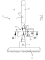
- Fig. 1
- eine schematische Draufsicht auf einen erfindungsgemäßen Türhebelmechanismus in seiner Verriegelungsposition;
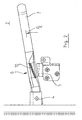
- Fig. 2.
- den Mechanismus gemäß
Fig. 1 in Entriegelungsposition und - Fig. 3
- eine vergrößerte Schnittdarstellung B-B gemäß
Fig. 1 .
- Fig. 1
- a schematic plan view of a door lever mechanism according to the invention in its locking position;
- Fig. 2.
- according to the mechanism
Fig. 1 in unlocking position and - Fig. 3
- an enlarged sectional view BB according to
Fig. 1 ,
In
Der Mechanismus 1 umfasst einen um eine horizontale Schwenkachse 4 schwenkbaren Hebel 3. Der Hebel 3 ist in
Ein Rastabschnitt 6 des Hebels 3 wirkt in der Verriegelungsposition PV mit einem Arretiermittel 5 zusammen, welches mit der Türe 2 fest verbunden ist und so ein freies Verschwenken des Hebels 3 zunächst verhindert, um ein unbeabsichtigtes Entriegeln der Türe zu vermeiden.A latching
Der Rastvorsprung 9 schließt in der dem Behälter abgewandten Richtung mit einer Außenkante K2 ab. Dagegen wird das freie Ende des oberen Schenkels 8' der Sicke 8 durch eine zum Behälter hin weisende Kante K1 begrenzt. Der erfindungsgemäße Türhebelmechanismus funktioniert in folgender Weise:The latching projection 9 terminates in the direction away from the container with an outer edge K 2 . In contrast, the free end of the upper leg 8 'of the
In der in
Aus der (in
Erfindungsgemäß wird der Rastabschnitt 6 durch die konstruktiv vorgesehene Vorspannkraft in der Verriegelungsposition gehalten, er muss also mit einer ausreichenden Betätigungskraft zur Türe hin gedrückt werden, um ihn von dort nach oben verschwenken zu können. Sobald die Kanten K1 und K2 einander während des Verschwenkens passiert haben, kann die Betätigungskraft am Hebel 3 wieder zurückgenommen werden, so dass der Hebel 6 der eingebauten Vorspannkraft nachgeben und sich wieder um ein Maß von der Türe 2 nach rechts hinüber bewegen kann.According to the latching
In umgekehrter Weise muss der Rastabschnitt 6 des Hebels 3 aus der in
Auf der nach außen bzw. oben gewandten Oberfläche des Rastvorsprunges 9 ist eine Vertiefung 10 vorgesehen, welche ein Einrasten der Kante K1 gestattet. Dadurch wird der Hebel 3 in seiner Verriegelungsposition Pv zusätzlich stabilisiert.On the outwardly or upwardly facing surface of the latching projection 9, a
Wie vorstehend erwähnt muss der Rastabschnitt 6 zum Lösen der Verriegelung um ein Maß in Richtung auf den Behälter gedrückt werden, so dass die Kanten K1 und K2 aneinander vorbei bewegbar sind. Dabei lässt sich die erforderliche Beaufschlagungskraft so weit reduzieren, dass der Hebel gerade so weit zur Tür hin gedrückt wird, dass die Kanten K1 und K2 beim Verschwenken des Hebels einander berühren. Bedingt durch die geneigten Flächen des Schenkels 8' bzw. des Rastvorsprunges 9 kann der Rastabschnitt 6 auch dadurch in Richtung zur Tür 2 hin verschoben werden, indem der Hebel 3 (ohne absichtliches Drücken in Richtung auf die Tür) gleich in Richtung auf die Entriegelungsposition PE verschwenkt wird. Naturgemäß wird er dabei durch die konstruktive Anordnung von Schenkel 8' und Rastvorsprung 9 in Richtung auf die Tür gedrückt, bis die beiden Kanten K1 und K2 einander berühren. Zur Vermeidung einer Punktlast an dieser Stelle, die durch die dem Hebel innewohnende Vorspannkraft recht groß werden kann, sind die beiden Kanten so ausgeführt, dass sie im Moment ihrer gegenseitigen Berührung entlang einer (vorzugsweise geraden) Berührlinie parallel zueinander verlaufen, so dass in dieser "kritischen" Hebelposition zumindest Linienkontakt besteht und verschleißerhöhende Punktlasten vermieden werden.As mentioned above, the locking
Ein weiterer Vorteil dieser konstruktiven Gestaltung liegt darin, dass der erforderliche Verschwenkwinkel minimiert wird, den der Hebel überstreichen muss, um aus der Ver- in die Entriegelungsposition zu gelangen. Liegen die Kanten K1 und K2 dagegen nicht parallel, so muss die Kante K2 (und damit der Hebel) so weit um die Achse 4 verschwenkt werden, bis die Kante K2 vollständig an der Kante K1 vorbeibewegt wurde, was einen größren Verschwenkwinkel verlangt. Dieser Effekt wirkt sich insbesondere dann vorteilhaft aus, wenn der Hebel in einer Vertiefung der Türe angeordnet ist, und diese bei kleinem Schwenkwinkel entsprechend klein ausfallen kann. Besonders günstig reduziert sich der Verschwenkwinkel dann, wenn die Berührlinie in ihrer gedachten Verlängerung die Achse 4 schneidet.Another advantage of this design is that the required pivot angle is minimized, the lever must sweep over to get out of the locking in the unlocked position. On the other hand, if the edges K 1 and K 2 are not parallel, then the edge K 2 (and thus the lever) must be pivoted so far about the
In
Claims (13)
dadurch gekennzeichnet,
characterized,
Priority Applications (1)
| Application Number | Priority Date | Filing Date | Title |
|---|---|---|---|
| PL10000367T PL2218851T3 (en) | 2009-02-12 | 2010-01-15 | Door lever mechanism |
Applications Claiming Priority (1)
| Application Number | Priority Date | Filing Date | Title |
|---|---|---|---|
| DE202009001785U DE202009001785U1 (en) | 2009-02-12 | 2009-02-12 | Door lever mechanism |
Publications (3)
| Publication Number | Publication Date |
|---|---|
| EP2218851A2 true EP2218851A2 (en) | 2010-08-18 |
| EP2218851A3 EP2218851A3 (en) | 2011-09-14 |
| EP2218851B1 EP2218851B1 (en) | 2014-08-06 |
Family
ID=40531130
Family Applications (1)
| Application Number | Title | Priority Date | Filing Date |
|---|---|---|---|
| EP10000367.2A Not-in-force EP2218851B1 (en) | 2009-02-12 | 2010-01-15 | Door lever mechanism |
Country Status (4)
| Country | Link |
|---|---|
| EP (1) | EP2218851B1 (en) |
| DE (1) | DE202009001785U1 (en) |
| ES (1) | ES2524797T3 (en) |
| PL (1) | PL2218851T3 (en) |
Cited By (1)
| Publication number | Priority date | Publication date | Assignee | Title |
|---|---|---|---|---|
| DE102018214389B3 (en) | 2018-08-27 | 2019-10-10 | Kermi Gmbh | Locking device for locking a door |
Family Cites Families (3)
| Publication number | Priority date | Publication date | Assignee | Title |
|---|---|---|---|---|
| DE69012685T2 (en) * | 1989-07-11 | 1995-05-04 | Fruehauf Japan | Locking construction of a handle for closing and opening a door. |
| DE9017294U1 (en) * | 1990-12-21 | 1991-03-14 | F. Hesterberg & Soehne Gmbh & Co Kg, 5828 Ennepetal, De | |
| US7073357B2 (en) * | 2004-05-06 | 2006-07-11 | Nixon Jr Willie E | Handle lock |
-
2009
- 2009-02-12 DE DE202009001785U patent/DE202009001785U1/en not_active Expired - Lifetime
-
2010
- 2010-01-15 EP EP10000367.2A patent/EP2218851B1/en not_active Not-in-force
- 2010-01-15 ES ES10000367.2T patent/ES2524797T3/en active Active
- 2010-01-15 PL PL10000367T patent/PL2218851T3/en unknown
Non-Patent Citations (1)
| Title |
|---|
| None |
Cited By (2)
| Publication number | Priority date | Publication date | Assignee | Title |
|---|---|---|---|---|
| DE102018214389B3 (en) | 2018-08-27 | 2019-10-10 | Kermi Gmbh | Locking device for locking a door |
| EP3617434A1 (en) | 2018-08-27 | 2020-03-04 | Kermi GmbH | Locking device for locking a door |
Also Published As
| Publication number | Publication date |
|---|---|
| PL2218851T3 (en) | 2015-02-27 |
| EP2218851B1 (en) | 2014-08-06 |
| ES2524797T3 (en) | 2014-12-12 |
| EP2218851A3 (en) | 2011-09-14 |
| DE202009001785U1 (en) | 2009-04-09 |
Similar Documents
| Publication | Publication Date | Title |
|---|---|---|
| EP2304139B1 (en) | Lock comprising a blocking lever in addition to a counterbalanced center of gravity | |
| EP2851497B1 (en) | Adjustable mounting device for a sliding element and sliding device | |
| EP0017765B1 (en) | Hydraulic lifting device | |
| EP2063060B1 (en) | Arrangement of a bar and a seal | |
| EP2440729A1 (en) | Motor vehicle lock comprising a mechanism helping to pull a door shut | |
| EP2362041B1 (en) | Mine safety lock for assembly on doors of military vehicles | |
| EP0411271B2 (en) | Lock for driving rod with an accessory lock which is controlled by a central lock | |
| CH653083A5 (en) | DOOR LOCK. | |
| DE112010000872B4 (en) | Container | |
| DE102017201971B4 (en) | Swivel armrest with locking mechanism | |
| EP3277899B1 (en) | Door handle assembly for a motor vehicle | |
| EP2697085A1 (en) | Sliding door for a vehicle | |
| EP2754800B1 (en) | Strike box or mortise lock | |
| EP0578004A2 (en) | Espagnolette with pivotal bolt actuated by a slot-guided spigot | |
| WO2013010203A1 (en) | Lock, more particularly mortise lock | |
| EP2218851B1 (en) | Door lever mechanism | |
| EP2784248A1 (en) | Drive unit for a fitting on a connecting rod | |
| EP1970508A2 (en) | Device for blocking a pivotable element in a motor vehicle | |
| EP3684992B1 (en) | Switch cabinet having improved locking mechanism | |
| EP2453086B1 (en) | Connecting rod for the fixed leaf of double-leafed windows or doors without mullion | |
| DE102017100149B4 (en) | Automatic door gap seal | |
| DE102005023224B4 (en) | Actuating device for the catch hook of a front hood | |
| EP1925765A2 (en) | Locking device for doors | |
| EP2085543B1 (en) | Lock | |
| EP2947223B1 (en) | Residential skylight tilting grip assembly, skylight with a skylight tilting grip assembly and method for mounting a skylight |
Legal Events
| Date | Code | Title | Description |
|---|---|---|---|
| PUAI | Public reference made under article 153(3) epc to a published international application that has entered the european phase |
Free format text: ORIGINAL CODE: 0009012 |
|
| AK | Designated contracting states |
Kind code of ref document: A2 Designated state(s): AT BE BG CH CY CZ DE DK EE ES FI FR GB GR HR HU IE IS IT LI LT LU LV MC MK MT NL NO PL PT RO SE SI SK SM TR |
|
| AX | Request for extension of the european patent |
Extension state: AL BA RS |
|
| PUAL | Search report despatched |
Free format text: ORIGINAL CODE: 0009013 |
|
| AK | Designated contracting states |
Kind code of ref document: A3 Designated state(s): AT BE BG CH CY CZ DE DK EE ES FI FR GB GR HR HU IE IS IT LI LT LU LV MC MK MT NL NO PL PT RO SE SI SK SM TR |
|
| AX | Request for extension of the european patent |
Extension state: AL BA RS |
|
| RIC1 | Information provided on ipc code assigned before grant |
Ipc: E05B 65/16 20060101ALI20110808BHEP Ipc: E05B 13/00 20060101AFI20110808BHEP |
|
| 17P | Request for examination filed |
Effective date: 20111223 |
|
| GRAP | Despatch of communication of intention to grant a patent |
Free format text: ORIGINAL CODE: EPIDOSNIGR1 |
|
| RIC1 | Information provided on ipc code assigned before grant |
Ipc: E05B 13/00 20060101ALI20131216BHEP Ipc: E05B 65/12 20060101AFI20131216BHEP |
|
| INTG | Intention to grant announced |
Effective date: 20140116 |
|
| GRAS | Grant fee paid |
Free format text: ORIGINAL CODE: EPIDOSNIGR3 |
|
| GRAP | Despatch of communication of intention to grant a patent |
Free format text: ORIGINAL CODE: EPIDOSNIGR1 |
|
| GRAA | (expected) grant |
Free format text: ORIGINAL CODE: 0009210 |
|
| INTG | Intention to grant announced |
Effective date: 20140623 |
|
| RIC1 | Information provided on ipc code assigned before grant |
Ipc: E05B 83/10 20140101ALI20140610BHEP Ipc: E05B 13/00 20060101AFI20140610BHEP |
|
| AK | Designated contracting states |
Kind code of ref document: B1 Designated state(s): AT BE BG CH CY CZ DE DK EE ES FI FR GB GR HR HU IE IS IT LI LT LU LV MC MK MT NL NO PL PT RO SE SI SK SM TR |
|
| REG | Reference to a national code |
Ref country code: GB Ref legal event code: FG4D Free format text: NOT ENGLISH |
|
| REG | Reference to a national code |
Ref country code: CH Ref legal event code: EP Ref country code: AT Ref legal event code: REF Ref document number: 681161 Country of ref document: AT Kind code of ref document: T Effective date: 20140815 |
|
| REG | Reference to a national code |
Ref country code: IE Ref legal event code: FG4D Free format text: LANGUAGE OF EP DOCUMENT: GERMAN |
|
| REG | Reference to a national code |
Ref country code: DE Ref legal event code: R096 Ref document number: 502010007582 Country of ref document: DE Effective date: 20140918 |
|
| REG | Reference to a national code |
Ref country code: ES Ref legal event code: FG2A Ref document number: 2524797 Country of ref document: ES Kind code of ref document: T3 Effective date: 20141212 |
|
| REG | Reference to a national code |
Ref country code: NL Ref legal event code: VDEP Effective date: 20140806 |
|
| REG | Reference to a national code |
Ref country code: LT Ref legal event code: MG4D |
|
| PG25 | Lapsed in a contracting state [announced via postgrant information from national office to epo] |
Ref country code: GR Free format text: LAPSE BECAUSE OF FAILURE TO SUBMIT A TRANSLATION OF THE DESCRIPTION OR TO PAY THE FEE WITHIN THE PRESCRIBED TIME-LIMIT Effective date: 20141107 Ref country code: PT Free format text: LAPSE BECAUSE OF FAILURE TO SUBMIT A TRANSLATION OF THE DESCRIPTION OR TO PAY THE FEE WITHIN THE PRESCRIBED TIME-LIMIT Effective date: 20141209 Ref country code: NO Free format text: LAPSE BECAUSE OF FAILURE TO SUBMIT A TRANSLATION OF THE DESCRIPTION OR TO PAY THE FEE WITHIN THE PRESCRIBED TIME-LIMIT Effective date: 20141106 Ref country code: BG Free format text: LAPSE BECAUSE OF FAILURE TO SUBMIT A TRANSLATION OF THE DESCRIPTION OR TO PAY THE FEE WITHIN THE PRESCRIBED TIME-LIMIT Effective date: 20141106 Ref country code: LT Free format text: LAPSE BECAUSE OF FAILURE TO SUBMIT A TRANSLATION OF THE DESCRIPTION OR TO PAY THE FEE WITHIN THE PRESCRIBED TIME-LIMIT Effective date: 20140806 Ref country code: SE Free format text: LAPSE BECAUSE OF FAILURE TO SUBMIT A TRANSLATION OF THE DESCRIPTION OR TO PAY THE FEE WITHIN THE PRESCRIBED TIME-LIMIT Effective date: 20140806 Ref country code: FI Free format text: LAPSE BECAUSE OF FAILURE TO SUBMIT A TRANSLATION OF THE DESCRIPTION OR TO PAY THE FEE WITHIN THE PRESCRIBED TIME-LIMIT Effective date: 20140806 |
|
| PG25 | Lapsed in a contracting state [announced via postgrant information from national office to epo] |
Ref country code: CY Free format text: LAPSE BECAUSE OF FAILURE TO SUBMIT A TRANSLATION OF THE DESCRIPTION OR TO PAY THE FEE WITHIN THE PRESCRIBED TIME-LIMIT Effective date: 20140806 Ref country code: LV Free format text: LAPSE BECAUSE OF FAILURE TO SUBMIT A TRANSLATION OF THE DESCRIPTION OR TO PAY THE FEE WITHIN THE PRESCRIBED TIME-LIMIT Effective date: 20140806 Ref country code: IS Free format text: LAPSE BECAUSE OF FAILURE TO SUBMIT A TRANSLATION OF THE DESCRIPTION OR TO PAY THE FEE WITHIN THE PRESCRIBED TIME-LIMIT Effective date: 20141206 Ref country code: NL Free format text: LAPSE BECAUSE OF FAILURE TO SUBMIT A TRANSLATION OF THE DESCRIPTION OR TO PAY THE FEE WITHIN THE PRESCRIBED TIME-LIMIT Effective date: 20140806 Ref country code: HR Free format text: LAPSE BECAUSE OF FAILURE TO SUBMIT A TRANSLATION OF THE DESCRIPTION OR TO PAY THE FEE WITHIN THE PRESCRIBED TIME-LIMIT Effective date: 20140806 |
|
| REG | Reference to a national code |
Ref country code: PL Ref legal event code: T3 |
|
| PG25 | Lapsed in a contracting state [announced via postgrant information from national office to epo] |
Ref country code: EE Free format text: LAPSE BECAUSE OF FAILURE TO SUBMIT A TRANSLATION OF THE DESCRIPTION OR TO PAY THE FEE WITHIN THE PRESCRIBED TIME-LIMIT Effective date: 20140806 Ref country code: SK Free format text: LAPSE BECAUSE OF FAILURE TO SUBMIT A TRANSLATION OF THE DESCRIPTION OR TO PAY THE FEE WITHIN THE PRESCRIBED TIME-LIMIT Effective date: 20140806 Ref country code: DK Free format text: LAPSE BECAUSE OF FAILURE TO SUBMIT A TRANSLATION OF THE DESCRIPTION OR TO PAY THE FEE WITHIN THE PRESCRIBED TIME-LIMIT Effective date: 20140806 Ref country code: RO Free format text: LAPSE BECAUSE OF FAILURE TO SUBMIT A TRANSLATION OF THE DESCRIPTION OR TO PAY THE FEE WITHIN THE PRESCRIBED TIME-LIMIT Effective date: 20140806 Ref country code: CZ Free format text: LAPSE BECAUSE OF FAILURE TO SUBMIT A TRANSLATION OF THE DESCRIPTION OR TO PAY THE FEE WITHIN THE PRESCRIBED TIME-LIMIT Effective date: 20140806 |
|
| REG | Reference to a national code |
Ref country code: DE Ref legal event code: R097 Ref document number: 502010007582 Country of ref document: DE |
|
| PLBE | No opposition filed within time limit |
Free format text: ORIGINAL CODE: 0009261 |
|
| STAA | Information on the status of an ep patent application or granted ep patent |
Free format text: STATUS: NO OPPOSITION FILED WITHIN TIME LIMIT |
|
| PG25 | Lapsed in a contracting state [announced via postgrant information from national office to epo] |
Ref country code: BE Free format text: LAPSE BECAUSE OF NON-PAYMENT OF DUE FEES Effective date: 20150131 |
|
| 26N | No opposition filed |
Effective date: 20150507 |
|
| REG | Reference to a national code |
Ref country code: CH Ref legal event code: PL |
|
| PG25 | Lapsed in a contracting state [announced via postgrant information from national office to epo] |
Ref country code: LU Free format text: LAPSE BECAUSE OF FAILURE TO SUBMIT A TRANSLATION OF THE DESCRIPTION OR TO PAY THE FEE WITHIN THE PRESCRIBED TIME-LIMIT Effective date: 20150115 |
|
| PG25 | Lapsed in a contracting state [announced via postgrant information from national office to epo] |
Ref country code: MC Free format text: LAPSE BECAUSE OF FAILURE TO SUBMIT A TRANSLATION OF THE DESCRIPTION OR TO PAY THE FEE WITHIN THE PRESCRIBED TIME-LIMIT Effective date: 20140806 |
|
| PG25 | Lapsed in a contracting state [announced via postgrant information from national office to epo] |
Ref country code: CH Free format text: LAPSE BECAUSE OF NON-PAYMENT OF DUE FEES Effective date: 20150131 Ref country code: LI Free format text: LAPSE BECAUSE OF NON-PAYMENT OF DUE FEES Effective date: 20150131 |
|
| REG | Reference to a national code |
Ref country code: IE Ref legal event code: MM4A |
|
| PG25 | Lapsed in a contracting state [announced via postgrant information from national office to epo] |
Ref country code: SI Free format text: LAPSE BECAUSE OF FAILURE TO SUBMIT A TRANSLATION OF THE DESCRIPTION OR TO PAY THE FEE WITHIN THE PRESCRIBED TIME-LIMIT Effective date: 20140806 |
|
| REG | Reference to a national code |
Ref country code: FR Ref legal event code: PLFP Year of fee payment: 7 |
|
| PG25 | Lapsed in a contracting state [announced via postgrant information from national office to epo] |
Ref country code: IE Free format text: LAPSE BECAUSE OF NON-PAYMENT OF DUE FEES Effective date: 20150115 |
|
| REG | Reference to a national code |
Ref country code: AT Ref legal event code: MM01 Ref document number: 681161 Country of ref document: AT Kind code of ref document: T Effective date: 20150115 |
|
| PGFP | Annual fee paid to national office [announced via postgrant information from national office to epo] |
Ref country code: DE Payment date: 20160329 Year of fee payment: 7 Ref country code: ES Payment date: 20160122 Year of fee payment: 7 Ref country code: IT Payment date: 20160122 Year of fee payment: 7 |
|
| PG25 | Lapsed in a contracting state [announced via postgrant information from national office to epo] |
Ref country code: AT Free format text: LAPSE BECAUSE OF NON-PAYMENT OF DUE FEES Effective date: 20150115 |
|
| PGFP | Annual fee paid to national office [announced via postgrant information from national office to epo] |
Ref country code: FR Payment date: 20160121 Year of fee payment: 7 Ref country code: GB Payment date: 20160122 Year of fee payment: 7 Ref country code: PL Payment date: 20160114 Year of fee payment: 7 |
|
| PG25 | Lapsed in a contracting state [announced via postgrant information from national office to epo] |
Ref country code: MT Free format text: LAPSE BECAUSE OF FAILURE TO SUBMIT A TRANSLATION OF THE DESCRIPTION OR TO PAY THE FEE WITHIN THE PRESCRIBED TIME-LIMIT Effective date: 20140806 |
|
| PG25 | Lapsed in a contracting state [announced via postgrant information from national office to epo] |
Ref country code: SM Free format text: LAPSE BECAUSE OF FAILURE TO SUBMIT A TRANSLATION OF THE DESCRIPTION OR TO PAY THE FEE WITHIN THE PRESCRIBED TIME-LIMIT Effective date: 20140806 Ref country code: HU Free format text: LAPSE BECAUSE OF FAILURE TO SUBMIT A TRANSLATION OF THE DESCRIPTION OR TO PAY THE FEE WITHIN THE PRESCRIBED TIME-LIMIT; INVALID AB INITIO Effective date: 20100115 |
|
| REG | Reference to a national code |
Ref country code: DE Ref legal event code: R119 Ref document number: 502010007582 Country of ref document: DE |
|
| PG25 | Lapsed in a contracting state [announced via postgrant information from national office to epo] |
Ref country code: TR Free format text: LAPSE BECAUSE OF FAILURE TO SUBMIT A TRANSLATION OF THE DESCRIPTION OR TO PAY THE FEE WITHIN THE PRESCRIBED TIME-LIMIT Effective date: 20140806 |
|
| GBPC | Gb: european patent ceased through non-payment of renewal fee |
Effective date: 20170115 |
|
| REG | Reference to a national code |
Ref country code: FR Ref legal event code: ST Effective date: 20170929 |
|
| PG25 | Lapsed in a contracting state [announced via postgrant information from national office to epo] |
Ref country code: FR Free format text: LAPSE BECAUSE OF NON-PAYMENT OF DUE FEES Effective date: 20170131 |
|
| PG25 | Lapsed in a contracting state [announced via postgrant information from national office to epo] |
Ref country code: DE Free format text: LAPSE BECAUSE OF NON-PAYMENT OF DUE FEES Effective date: 20170801 Ref country code: GB Free format text: LAPSE BECAUSE OF NON-PAYMENT OF DUE FEES Effective date: 20170115 |
|
| PG25 | Lapsed in a contracting state [announced via postgrant information from national office to epo] |
Ref country code: IT Free format text: LAPSE BECAUSE OF NON-PAYMENT OF DUE FEES Effective date: 20170115 |
|
| PG25 | Lapsed in a contracting state [announced via postgrant information from national office to epo] |
Ref country code: ES Free format text: LAPSE BECAUSE OF NON-PAYMENT OF DUE FEES Effective date: 20170116 |
|
| PG25 | Lapsed in a contracting state [announced via postgrant information from national office to epo] |
Ref country code: MK Free format text: LAPSE BECAUSE OF FAILURE TO SUBMIT A TRANSLATION OF THE DESCRIPTION OR TO PAY THE FEE WITHIN THE PRESCRIBED TIME-LIMIT Effective date: 20140806 |
|
| PG25 | Lapsed in a contracting state [announced via postgrant information from national office to epo] |
Ref country code: PL Free format text: LAPSE BECAUSE OF NON-PAYMENT OF DUE FEES Effective date: 20170115 |
|
| REG | Reference to a national code |
Ref country code: ES Ref legal event code: FD2A Effective date: 20181107 |