EP2218675A2 - Hydrostatisches Antriebsystem einer mobilen Arbeitsmaschine - Google Patents
Hydrostatisches Antriebsystem einer mobilen Arbeitsmaschine Download PDFInfo
- Publication number
- EP2218675A2 EP2218675A2 EP10000411A EP10000411A EP2218675A2 EP 2218675 A2 EP2218675 A2 EP 2218675A2 EP 10000411 A EP10000411 A EP 10000411A EP 10000411 A EP10000411 A EP 10000411A EP 2218675 A2 EP2218675 A2 EP 2218675A2
- Authority
- EP
- European Patent Office
- Prior art keywords
- pressure
- pump
- valve
- control
- drive system
- Prior art date
- Legal status (The legal status is an assumption and is not a legal conclusion. Google has not performed a legal analysis and makes no representation as to the accuracy of the status listed.)
- Withdrawn
Links
- 230000002706 hydrostatic effect Effects 0.000 title claims description 14
- 238000006073 displacement reaction Methods 0.000 claims abstract description 7
- 238000011144 upstream manufacturing Methods 0.000 claims abstract description 7
- 230000036316 preload Effects 0.000 claims description 5
- 230000000903 blocking effect Effects 0.000 claims description 4
- 230000001276 controlling effect Effects 0.000 abstract description 3
- 230000001105 regulatory effect Effects 0.000 abstract description 3
- 238000010276 construction Methods 0.000 description 4
- 238000005265 energy consumption Methods 0.000 description 4
- 238000002485 combustion reaction Methods 0.000 description 2
- 238000010586 diagram Methods 0.000 description 2
Images

Classifications
-
- B—PERFORMING OPERATIONS; TRANSPORTING
- B66—HOISTING; LIFTING; HAULING
- B66F—HOISTING, LIFTING, HAULING OR PUSHING, NOT OTHERWISE PROVIDED FOR, e.g. DEVICES WHICH APPLY A LIFTING OR PUSHING FORCE DIRECTLY TO THE SURFACE OF A LOAD
- B66F9/00—Devices for lifting or lowering bulky or heavy goods for loading or unloading purposes
- B66F9/06—Devices for lifting or lowering bulky or heavy goods for loading or unloading purposes movable, with their loads, on wheels or the like, e.g. fork-lift trucks
- B66F9/075—Constructional features or details
- B66F9/20—Means for actuating or controlling masts, platforms, or forks
- B66F9/22—Hydraulic devices or systems
-
- F—MECHANICAL ENGINEERING; LIGHTING; HEATING; WEAPONS; BLASTING
- F15—FLUID-PRESSURE ACTUATORS; HYDRAULICS OR PNEUMATICS IN GENERAL
- F15B—SYSTEMS ACTING BY MEANS OF FLUIDS IN GENERAL; FLUID-PRESSURE ACTUATORS, e.g. SERVOMOTORS; DETAILS OF FLUID-PRESSURE SYSTEMS, NOT OTHERWISE PROVIDED FOR
- F15B11/00—Servomotor systems without provision for follow-up action; Circuits therefor
- F15B11/16—Servomotor systems without provision for follow-up action; Circuits therefor with two or more servomotors
- F15B11/161—Servomotor systems without provision for follow-up action; Circuits therefor with two or more servomotors with sensing of servomotor demand or load
- F15B11/162—Servomotor systems without provision for follow-up action; Circuits therefor with two or more servomotors with sensing of servomotor demand or load for giving priority to particular servomotors or users
-
- F—MECHANICAL ENGINEERING; LIGHTING; HEATING; WEAPONS; BLASTING
- F15—FLUID-PRESSURE ACTUATORS; HYDRAULICS OR PNEUMATICS IN GENERAL
- F15B—SYSTEMS ACTING BY MEANS OF FLUIDS IN GENERAL; FLUID-PRESSURE ACTUATORS, e.g. SERVOMOTORS; DETAILS OF FLUID-PRESSURE SYSTEMS, NOT OTHERWISE PROVIDED FOR
- F15B2211/00—Circuits for servomotor systems
- F15B2211/50—Pressure control
- F15B2211/505—Pressure control characterised by the type of pressure control means
- F15B2211/50554—Pressure control characterised by the type of pressure control means the pressure control means controlling a pressure downstream of the pressure control means, e.g. pressure reducing valve
-
- F—MECHANICAL ENGINEERING; LIGHTING; HEATING; WEAPONS; BLASTING
- F15—FLUID-PRESSURE ACTUATORS; HYDRAULICS OR PNEUMATICS IN GENERAL
- F15B—SYSTEMS ACTING BY MEANS OF FLUIDS IN GENERAL; FLUID-PRESSURE ACTUATORS, e.g. SERVOMOTORS; DETAILS OF FLUID-PRESSURE SYSTEMS, NOT OTHERWISE PROVIDED FOR
- F15B2211/00—Circuits for servomotor systems
- F15B2211/60—Circuit components or control therefor
- F15B2211/635—Circuits providing pilot pressure to pilot pressure-controlled fluid circuit elements
- F15B2211/6355—Circuits providing pilot pressure to pilot pressure-controlled fluid circuit elements having valve means
-
- F—MECHANICAL ENGINEERING; LIGHTING; HEATING; WEAPONS; BLASTING
- F15—FLUID-PRESSURE ACTUATORS; HYDRAULICS OR PNEUMATICS IN GENERAL
- F15B—SYSTEMS ACTING BY MEANS OF FLUIDS IN GENERAL; FLUID-PRESSURE ACTUATORS, e.g. SERVOMOTORS; DETAILS OF FLUID-PRESSURE SYSTEMS, NOT OTHERWISE PROVIDED FOR
- F15B2211/00—Circuits for servomotor systems
- F15B2211/70—Output members, e.g. hydraulic motors or cylinders or control therefor
- F15B2211/705—Output members, e.g. hydraulic motors or cylinders or control therefor characterised by the type of output members or actuators
- F15B2211/7058—Rotary output members
Definitions
- the invention relates to a hydrostatic drive system of a mobile work machine, in particular an industrial truck, with a pump and at least one power supplied by the pump load a working hydraulics, which can be actuated by means of an electro-hydraulically actuated control valve, in particular a directional control valve, wherein for actuating the control valve at least an electrically actuable pilot valve is provided which is in communication with a control pressure supply line.
- a control pressure supply with a constant control pressure level is required, from which by means of appropriate pilot valves, a control pressure is generated for actuating the control valves.
- From the DE 102 24 731 A1 is a generic hydrostatic drive system designed as a truck work machine in which an additional designed as a constant pump pump is provided in the form of a feed pump for generating the constant control pressure for the electro-hydraulically operated control valves of the working hydraulics.
- an additional designed as a constant pump pump is provided in the form of a feed pump for generating the constant control pressure for the electro-hydraulically operated control valves of the working hydraulics.
- two pumps are required, resulting in a high construction cost of the drive system.
- To protect the feed pressure level of the feed pump or the feed pressure supply line is usually associated with a pressure relief valve.
- the present invention has for its object to provide a hydrostatic drive system of the type mentioned, the is improved in terms of energy consumption and heat load of the pressure medium and has a low construction cost.
- the pump is further provided to supply another consumer, in particular a hydraulic steering, wherein in the delivery line of the pump for preferential supply of the further consumer, a priority valve is arranged and connected the control pressure supply line upstream of the priority valve to the delivery line of the pump is.
- a priority valve is arranged and connected the control pressure supply line upstream of the priority valve to the delivery line of the pump is.
- the priority valve is expediently acted upon by means of a spring in the direction of a conveying line connecting the pump to the steering position.
- the pending before the priority valve system pressure is co-determined by the spring bias of the spring of the priority valve, which can be provided from the system pressure in a simple way, the control pressure for pilot control of the control valves of the working hydraulics.
- the drive system according to the invention can be designed as a so-called open-center system in which the pump is designed as a fixed displacement pump and the control valve is associated with a circulation pressure, the highest load pressure of the load of the working hydraulics and a spring in the direction of a blocking position and the delivery pressure of the Pump is applied in the direction of a flow position.
- the system pressure in particular for non-actuated consumers, also determined by the spring bias of the spring of the rotary pressure balance, which with the connected to the delivery line of the pump control pressure supply line and arranged in this pressure reducing valve in a simple manner required for actuating the control valves control pressure can be generated.
- the spring bias of the priority valve and / or the spring preload of the recirculation pressure balance are set such that at each operating point a minimum control pressure level can be generated in the control pressure supply line. This ensures in a simple manner that in the control pressure supply line required for the actuation of the control valves and certain of the setting of the pressure reducing valve pilot pressure is present in all operating conditions.
- the drive system according to the invention can also be designed as a so-called closed-center system, in which the pump is designed as a load-sensing variable-displacement pump, which is the highest load pressure of the working hydraulics and / or the further consumer is controlled.
- a variable delivers when not driven consumers of the working hydraulics and / or non-actuated steering a standby pressure as a control variable of the variable, from the means connected to the delivery line of the pump control pressure supply line and arranged in this pressure reducing valve in a simple way, the control pressure for actuating the Control valves can be generated.
- the standby pressure and thus the controlled variable of the pump and / or the spring bias of the priority valve are set such that at each operating point a minimum control pressure level in the control pressure supply line can be generated, the required control pressure for Actuation of the control valves are easily generated in all operating conditions from the system pressure generated by the pump.
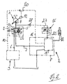
- FIG. 1 is an inventive, designed as an open-center system drive system of a designed example, designed as a truck work machine in a schematic circuit diagram.
- the drive system comprises a fixed-displacement pump 1, which is operated in the open circuit and for supplying a working hydraulics 2 and another consumer, which is formed by a hydraulic steering 3, is provided.
- the pump 1 sucks from a container and delivers into a delivery line 4, in which a priority valve 5 is arranged for the preferred supply of the steering 3. From the priority valve 5 leads a delivery branch line 6 to the Steering 3 and a delivery branch line 7 to a control valve block 8 of the working hydraulics. 2
- the priority valve 5 is acted upon by means of a spring 9 and in a load pressure branch line 10 of the steering 3 load pressure of the steering 3 in the direction of a conveying line 4 with the delivery branch line 6 for the preferred supply of the steering 3 connecting position 5a.
- the priority valve 5 can be acted upon in the direction of a position 5b, in which the delivery line 4 is connected to both delivery branch lines 6 and 7 for the simultaneous supply of the steering 3 and the working hydraulics 2.
- the control valve block 8 of the working hydraulics 2 comprises a control valve designed as a directional control valve for controlling each consumer of the working hydraulics 2.
- control valves 11 for actuating a lifting drive 12, a tilt drive, not shown, and possibly an auxiliary drive, not shown, for example, a side slide, the working hydraulics 2 are provided.
- a circulation pressure compensator 15 is arranged, which is arranged in a guided from the delivery branch line 7 to the container branch line.
- the circulation pressure compensator 15 is acted upon by the highest load pressure of the consumers of the working hydraulics 2 and of a spring 17 in the direction of a blocking position and of the delivery pressure present in the delivery branch line 7 in the direction of a flow-through position in a load pressure branch line 16.
- To protect the load pressure branch line 16 of the working hydraulics 2 may be associated with a pressure relief valve 18.
- FIG. 2 is an inventive, designed as a closed-center system drive system of an example designed as a truck work machine shown in a schematic circuit diagram.
- the same components are provided here with the same reference numerals.
- the pump 1 provided for supplying the working hydraulics 2 and the further load formed by the hydraulic steering 3 is designed as a load-sensing-controlled variable displacement pump.
- a demand flow control device 19 is provided, which is controlled by the highest load pressure of the steering 3 and the highest load pressure of the working hydraulics 2.
- the load pressure branch line 10 of the steering system 3 and the load pressure branch line 16 of the working hydraulics 2 can in this case be connected to the inputs of a shuttle valve device 20 which is connected on the output side to the demand flow regulating device 19 of the pump 1.
- the control valves 11 for controlling the load of the working hydraulics 2 according to the FIGS. 1 and 2 are each electro-hydraulically actuated.
- electrically controlled pilot valves for example by means of a proportional solenoid operated pressure reducing valves, provided by means of which the control valves 11 actuated control pressures can be generated.
- the pilot valves are on the input side with a control pressure supply line 25 in connection.
- control pressure supply line 25 guided to a control pressure connection of the control valve block 8 of the working hydraulics 2 is connected to the delivery line 4 of the pump 1 supplying the working hydraulics 2 and the steering 3 upstream of the priority valve 5.
- a pressure-reducing valve 26 designed as a hydraulically controlled pressure reducing valve is arranged to generate a constant control pressure level whose setting defines the control pressure level at the control pressure port of the control valve block 8.
- the pressure reducing valve 26 is provided with a spring 27. Upstream of the pressure reducing valve 26 is in the control pressure supply line 25 in the direction of the pressure reducing valve 26 opening check valve 28 is arranged, which is designed as a check valve.
- the pump 1 In a drive system according to the FIG. 1 or the FIG. 2 the pump 1, the flow for supplying the load of the working hydraulics 2 and the other consumer formed by the steering 3 available.
- the priority valve 5 prioritizes the steering 3 when actuated before the working hydraulics 2 with simultaneous operation of the steering 3 and the working hydraulics 2.
- the spring bias of the spring 9 of the priority valve 5 changes the performance of the priority valve 5 and determines the flow resistance and thus the pressure drop across the priority valve 5.
- the priority valve 5 is acted upon in the position 5b, in which the flow of the pump 1 is completely the Control valve block 8 and thus the control valves 11 of the working hydraulics 2 flows.
- the priority valve 5 in this case occurs on a pressure difference, which is in direct dependence on the spring bias of the spring 9.
- the circulation pressure compensator 15 In non-actuated control valves 11 of the working hydraulics 2, the circulation pressure compensator 15 according to the FIG. 1 acted upon in the flow position, provided that in the delivery branch line 7 pending system pressure exceeds the spring preload of the spring 17 of the rotary pressure compensator 15. As a result, flows in unconfirmed consumers of the working hydraulics 2 and uncontrolled steering 3, the full flow of the pump 1 via the priority valve 5 and the circulation pressure compensator 15 to the container.
- the pressure difference at the circulation pressure compensator 15 is here in direct dependence on the spring preload of the spring 17.
- the minimum control pressure is defined in the control pressure supply line, which is required for pilot control and thus actuation of the control valves 8.
- the spring bias of the spring 9 of the priority valve 5 and the spring bias of the spring 17 of the rotary pressure compensator are in the drive system according to the invention according to the FIG. 1 tuned so that when un-actuated consumers, the sum of the pressure difference at the priority valve 5 and the pressure difference at the orbital pressure regulator 15 plus the line resistance and flow resistance of other components at least the minimum control pressure, which is defined by the spring 27, whereby the pilot pressure for actuating the Control valves 11 of the working hydraulics 2 can be provided from the system pressure generated by the pump 1 in the delivery line 4 in all operating conditions.
- a drive system according to the invention according to the FIG. 2 is set in non-actuated consumers of the working hydraulics 2 and non-actuated steering system pressure 3 in the delivery line 4 from the sum of, for example, a spring on the demand flow control device 19 standby pressure of the pump 1 and the pressure difference across the priority valve 5 and the line resistances and flow resistances of other components together.
- a spring on the demand flow control device 19 standby pressure of the pump 1 and the pressure difference across the priority valve 5 and the line resistances and flow resistances of other components together.
- the minimum system pressure of the pump 1 is the sum of the lowest load pressure of the load of the working hydraulics 2, of which the circulation pressure compensator 15 is acted upon in the blocking position or the demand flow control device 19 of the pump 1 is applied, and the pressure difference at the priority valve 5 plus the line resistance and flow resistance of other components together.
- the minimum system pressure of the pump 1 at the lowest load of the working hydraulics corresponds to at least the minimum control pressure defined by the spring 27, whereby the system pressure generated by the pump 1 can be used to provide the pilot pressure for actuating the control valves 11 of the working hydraulics.
- an external control pressure supply for the electro-hydraulically actuated and pilot operated control valves 11 of the working hydraulics 2 can be achieved with constant control pressure from the system pressure generated by the pump 1 ,
- a control pressure supply with a constant control pressure level for the electro-hydraulically actuated control valves 11 of the working hydraulics 2 in an open-center system according to FIG. 1 or as a closed-center system according to the FIG. 2 trained hydrostatic drive system can be achieved from the system pressure generated by the pump 1.
- the invention can in this case in internal combustion engine operated forklifts, in which the pump 1 is driven by an internal combustion engine, or electrically, in particular battery-electrically operated industrial trucks, in which the pump 1 is driven by an electric motor, are used.
- a brake release device of a parking brake and / or a hydrostatic fan device can be actuated and driven by the pump 1, for example a brake release device of a parking brake and / or a hydrostatic fan device.
Landscapes
- Engineering & Computer Science (AREA)
- Structural Engineering (AREA)
- Mechanical Engineering (AREA)
- Transportation (AREA)
- Fluid Mechanics (AREA)
- General Engineering & Computer Science (AREA)
- Chemical & Material Sciences (AREA)
- Combustion & Propulsion (AREA)
- Civil Engineering (AREA)
- Physics & Mathematics (AREA)
- Life Sciences & Earth Sciences (AREA)
- Geology (AREA)
- Fluid-Pressure Circuits (AREA)
Abstract
Description
- Die Erfindung betrifft ein hydrostatisches Antriebssystem einer mobilen Arbeitsmaschine, insbesondere eines Flurförderzeugs, mit einer Pumpe und mindestens einem von der Pumpe versorgbaren Verbraucher einer Arbeitshydraulik, der mittels eines elektro-hydraulisch betätigbaren Steuerventils, insbesondere eines Wegeventils, betätigbar ist, wobei zur Betätigung des Steuerventils mindestens ein elektrisch betätigbares Vorsteuerventil vorgesehen ist, das mit einer Steuerdruckversorgungsleitung in Verbindung steht.
- Bei elektro-hydraulisch betätigten und vorgesteuerten Steuerventilen ist zur Erzielung hoher Betätigungskräfte für das Steuerventil eine Steuerdruckversorgung mit einem konstanten Steuerdruckniveau erforderlich, aus dem mittels entsprechender Vorsteuerventile ein Steuerdruck zur Betätigung der Steuerventile erzeugt wird.
- Aus der
DE 102 24 731 A1 ist ein gattungsgemäßes hydrostatisches Antriebssystem einer als Flurförderzeug ausgebildeten Arbeitsmaschine bekannt, bei der zur Erzeugung des konstanten Steuerdrucks für die elektro-hydraulisch betätigten Steuerventile der Arbeitshydraulik eine zusätzliche als Konstantpumpe ausgebildete Pumpe in Form einer Speisepumpe vorgesehen ist. Bei dem aus derDE 102 24 731 A1 bekannten Antriebssystem sind somit zwei Pumpen erforderlich, wodurch sich ein hoher Bauaufwand des Antriebssystems ergibt. Zur Absicherung des Speisedruckniveaus ist der Speisepumpe bzw. der Speisedruckversorgungsleitung in der Regel ein Druckbegrenzungsventil zugeordnet. Die Abdrosselung des von der Speisepumpe geförderten und nicht benötigten Steuerdrucks und somit des ungenutzten Steuerdruckvolumenstroms, insbesondere bei unbetätigten Steuerventilen, an dem Druckbegrenzungsventil führt zu hohen hydraulischen Verlusten, die zu einem hohen Energieverbrauch des Antriebssystems und einer hohen Wärmebelastung des Druckmittels führen. - Der vorliegenden Erfindung liegt die Aufgabe zugrunde, ein hydrostatisches Antriebssystem der eingangs genannten Gattung zur Verfügung zu stellen, das hinsichtlich des Energieverbrauchs und der Wärmebelastung des Druckmittels verbessert ist und einen geringen Bauaufwand aufweist.
- Diese Aufgabe wird erfindungsgemäß dadurch gelöst, dass zur Erzeugung des in der Steuerdruckversorgungsleitung anstehenden Steuerdrucks ein mit der Förderleitung der Pumpe in Verbindung stehendes Druckminderventil vorgesehen ist. Erfindungsgemäß wird somit der konstante Steuerdruck zur Vorsteuerung und Betätigung der Steuerventile der Arbeitshydraulik direkt von der Pumpe der Arbeitshydraulik aus dem in der Förderleitung der Pumpe anstehenden Systemdruck erzeugt und bereit gestellt. Durch die erfindungsgemäße Nutzung des von der Pumpe der Arbeitshydraulik erzeugten und somit vorhandenen Systemdrucks zum Bereitstellen des konstanten Steuerdrucks zur Vorsteuerung der Steuerventile sind durch den Entfall einer separaten Pumpe, beispielsweise einer Speisepumpe, zur Erzeugung des Steuerdrucks ein geringer Bauaufwand und ein verringerter Energieverbrauch erzielbar. Durch die Verwendung eines Druckminderventils entfällt zudem ein bislang erforderliches Druckbegrenzungsventil zur Absicherung des Steuerdruckniveaus, so dass keine Abdrosselung des ungenutzten Steuerdruckvolumenstroms zum Behälter auftritt, wodurch der Wärmeeintrag in das Druckmittel des Antriebssystems verringert werden kann.
- Besondere Vorteile ergeben sich, wenn gemäß einer vorteilhaften Weiterbildung der Erfindung in der Steuerdruckversorgungsleitung stromauf des Druckminderventils ein in Richtung zum Druckminderventil öffnendes Sperrventil, insbesondere Rückschlagventil, angeordnet ist. Beim Abschalten der Pumpe, insbesondere bei einer Arbeitsmaschine mit einem elektrischen, beispielsweise batterie-elektrischen, Antrieb der Pumpe kann mit dem Sperrventil der in der Steuerdruckversorgungsleitung anstehende Steuerdruck auf einfache Weise eingespannt werden.
- Gemäß einer Weiterbildung der Erfindung ist die Pumpe weiterhin zur Versorgung eines weiteren Verbrauchers, insbesondere einer hydraulischen Lenkung, vorgesehen, wobei in der Förderleitung der Pumpe zur bevorzugten Versorgung des weiteren Verbrauchers ein Prioritätsventil angeordnet ist und die Steuerdruckversorgungsleitung stromauf des Prioritätsventils an die Förderleitung der Pumpe angeschlossen ist. Hierdurch kann der vor dem Prioritätsventil anstehende Systemdruck der Pumpe der Arbeitshydraulik in energiesparender Weise zur Erzeugung des Steuerdrucks verwendet werden.
- Das Prioritätsventil ist hierbei zweckmäßigerweise mittels einer Feder in Richtung einer die Förderleitung der Pumpe mit der Lenkung verbindenden Stellung beaufschlagt ist. Der vor dem Prioritätsventil anstehende Systemdruck wird von der Federvorspannung der Feder des Prioritätsventils mitbestimmt, wodurch aus dem Systemdruck auf einfache Weise der Steuerdruck zur Vorsteuerung der Steuerventile der Arbeitshydraulik bereit gestellt werden kann.
- Das erfindungsgemäße Antriebssystem kann als sogenanntes Open-Center-System ausgebildet sein, bei dem die Pumpe als Konstantpumpe ausgebildet ist und dem Steuerventil eine Umlaufdruckwaage zugeordnet ist, die von dem höchsten Lastdruck der Verbraucher der Arbeitshydraulik und einer Feder in Richtung einer Sperrstellung und dem Förderdruck der Pumpe in Richtung einer Durchflussstellung beaufschlagt ist. Bei einem derartigen Antriebssystem wird der Systemdruck, insbesondere bei nicht betätigten Verbrauchern, ebenfalls von der Federvorspannung der Feder der Umlaufdruckwaage bestimmt, wodurch mit der an die Förderleitung der Pumpe angeschlossenen Steuerdruckversorgungsleitung und dem in dieser angeordneten Druckminderventil auf einfache Weise der zur Betätigung der Steuerventile erforderliche Steuerdruck erzeugt werden kann.
- Um den zur Betätigung der Steuerventile erforderlichen Steuerdruck hierbei in allen Betriebszuständen aus dem von der Pumpe gelieferten Systemdruck zu erzeugen, sind die Federvorspannung des Prioritätsventils und/oder die Federvorspannung der Umlaufdruckwaage gemäß einer bevorzugten Ausgestaltungsform der Erfindung derart eingestellt, dass in jedem Betriebspunkt ein minimales Steuerdruckniveau in der Steuerdruckversorgungsleitung erzeugbar ist. Hierdurch wird auf einfache Weise sichergestellt, dass in der Steuerdruckversorgungsleitung der zur Betätigung der Steuerventile erforderliche und von der Einstellung des Druckminderventils bestimmte Vorsteuerdruck in allen Betriebszuständen ansteht.
- Das erfindungsgemäße Antriebssystem kann ebenfalls als sogenanntes Closed-Center-System ausgebildet sein, bei dem die Pumpe als Load-Sensing-geregelte Verstellpumpe ausgebildet ist, die von dem höchsten Lastdruck der Arbeitshydraulik und/oder des weiteren Verbrauchers gesteuert ist. Eine derartige Verstellpumpe liefert bei nicht angesteuerten Verbrauchern der Arbeitshydraulik und/oder nicht betätigter Lenkung einen Standby-Druck als Regelgröße der Verstellpumpe, aus dem mittels der an die Förderleitung der Pumpe angeschlossenen Steuerdruckversorgungsleitung und dem in dieser angeordneten Druckminderventil auf einfache Weise der Steuerdruck zur Betätigung der Steuerventile erzeugt werden kann.
- Sofern gemäß einer vorteilhaften Ausführungsform der Erfindung bei einem derartigen Antriebssystem der Standby-Druck und somit die Regelgröße der Pumpe und/oder die Federvorspannung des Prioritätsventils derart eingestellt sind, dass in jedem Betriebspunkt ein minimales Steuerdruckniveau in der Steuerdruckversorgungsleitung erzeugbar ist, kann der erforderliche Steuerdruck zur Betätigung der Steuerventile auf einfache Weise in allen Betriebszuständen aus dem von der Pumpe erzeugten Systemdruck erzeugt werden.
- Weitere Vorteile und Einzelheiten der Erfindung werden anhand der in den schematischen Figuren dargestellten Ausführungsbeispiele näher erläutert. Hierbei zeigen
- Figur 1
- eine erste Ausführungsform eines erfindungsgemäßen Antriebssystems und
- Figur 2
- eine zweite Ausführungsform eines erfindungsgemäßen Antriebssystems.
- In der
Figur 1 ist ein erfindungsgemäßes, als Open-Center-System ausgebildetes Antriebssystem einer beispielsweise als Flurförderzeug ausgebildeten Arbeitsmaschine in einem schematischen Schaltplan dargestellt. - Das Antriebssystem umfasst eine als Konstantpumpe ausgebildete Pumpe 1, die im offenen Kreislauf betrieben ist und zur Versorgung einer Arbeitshydraulik 2 und eines weiteren Verbrauchers, der von einer hydraulischen Lenkung 3 gebildet ist, vorgesehen ist. Die Pumpe 1 saugt aus einem Behälter und fördert in eine Förderleitung 4, in der zur bevorzugten Versorgung der Lenkung 3 eine Prioritätsventil 5 angeordnet ist. Von dem Prioritätsventil 5 führt eine Förderzweigleitung 6 zu der Lenkung 3 und eine Förderzweigleitung 7 zu einem Steuerventilblock 8 der Arbeitshydraulik 2.
- Das Prioritätsventil 5 ist mittels einer Feder 9 und dem in einer Lastdruckzweigleitung 10 der Lenkung 3 anstehenden Lastdruck der Lenkung 3 in Richtung einer die Förderleitung 4 mit der Förderzweigleitung 6 zur bevorzugten Versorgung der Lenkung 3 verbindenden Stellung 5a beaufschlagbar. Mittels des in der Förderzweigleitung 6 anstehenden Förderdruckes ist das Prioritätsventil 5 in Richtung einer Stellung 5b beaufschlagbar, in der die Förderleitung 4 mit beiden Förderzweigleitungen 6 und 7 zur gleichzeitigen Versorgung der Lenkung 3 und der Arbeitshydraulik 2 verbunden ist.
- Der Steuerventilblock 8 der Arbeitshydraulik 2 umfasst zur Steuerung jedes Verbrauchers der Arbeitshydraulik 2 ein als Wegeventil ausgebildetes Steuerventil. In der
Figur 1 sind schematisch dargestellte Steuerventile 11 zur Betätigung eines Hubantriebs 12, eines nicht mehr dargestellten Neigeantriebs und gegebenenfalls eines nicht mehr dargestellten Zusatzantriebs, beispielsweise eines Seitenschiebers, der Arbeitshydraulik 2 vorgesehen. - In dem Steuerventilblock 8 der Arbeitshydraulik 2 ist gemäß der
Figur 1 eine Umlaufdruckwaage 15 angeordnet, die in einer von der Förderzweigleitung 7 zum Behälter geführten Zweigleitung angeordnet ist. Die Umlaufdruckwaage 15 ist von dem in einer Lastdruckzweigleitung 16 anstehenden, höchsten Lastdruck der Verbraucher der Arbeitshydraulik 2 und einer Feder 17 in Richtung einer Sperrstellung und von dem in der Förderzweigleitung 7 anstehenden Förderdruck in Richtung einer Durchflussstellung beaufschlagt. Zur Absicherung kann der Lastdruckzweigleitung 16 der Arbeitshydraulik 2 ein Druckbegrenzungsventil 18 zugeordnet sein. - In der
Figur 2 ist ein erfindungsgemäßes, als Closed-Center-System ausgebildetes Antriebssystem einer beispielsweise als Flurförderzeug ausgebildeten Arbeitsmaschine in einem schematischen Schaltplan dargestellt. Gleiche Bauteile sind hierbei mit gleichen Bezugsziffern versehen. - Die zur Versorgung der Arbeitshydraulik 2 und des von der hydraulischen Lenkung 3 gebildeten weiteren Verbrauchers vorgesehene Pumpe 1 ist als Load-Sensing-geregelte Verstellpumpe ausgebildet. Zur Regelung der Fördermenge der Pumpe 1 ist eine Bedarfsstromregeleinrichtung 19 vorgesehen, die von dem höchsten Lastdruck der Lenkung 3 bzw. dem höchsten Lastdruck der Arbeitshydraulik 2 gesteuert ist. Die Lastdruckzweigleitung 10 der Lenkung 3 sowie die Lastdruckzweigleitung 16 der Arbeitshydraulik 2 können hierbei an die Eingänge einer Wechselventileinrichtung 20 angeschlossen sein, die ausgangsseitig mit der Bedarfsstromregeleinrichtung 19 der Pumpe 1 in Verbindung steht.
- Die Steuerventile 11 zur Steuerung der Verbraucher der Arbeitshydraulik 2 gemäß den
Figuren 1 und2 sind jeweils elektro-hydraulisch betätigbar. Hierzu sind nicht näher dargestellte elektrisch angesteuerte Vorsteuerventile, beispielsweise mittels eines Proportionalmagneten betätigte Druckminderventile, vorgesehen, mittels denen die Steuerventile 11 betätigende Steuerdrücke erzeugbar sind. Die Vorsteuerventile stehen eingangsseitig mit einer Steuerdruckversorgungsleitung 25 in Verbindung. - Erfindungsgemäß ist die an einen Steuerdruckanschluss des Steuerventilblocks 8 der Arbeitshydraulik 2 geführte Steuerdruckversorgungsleitung 25 an die Förderleitung 4 der die Arbeitshydraulik 2 und die Lenkung 3 versorgenden Pumpe 1 stromauf des Prioritätsventils 5 angeschlossen. In der Steuerdruckversorgungsleitung 25 ist zur Erzeugung eines konstanten Steuerdruckniveaus ein als Druckminderventil 26 ausgebildetes, hydraulisch gesteuertes Druckreduzierventil angeordnet, dessen Einstellung das Steuerdruckniveau am Steuerdruckanschluss des Steuerventilblocks 8 definiert. Zur Einstellung des Steuerdruckniveaus ist das Druckminderventil 26 mit einer Feder 27 versehen. Stromauf des Druckminderventils 26 ist in der Steuerdruckversorgungsleitung 25 ein in Richtung zum Druckminderventil 26 öffnendes Sperrventil 28 angeordnet, das als Rückschlagventil ausgebildet ist.
- Bei einem Antriebssystem gemäß der
Figur 1 bzw. derFigur 2 stellt die Pumpe 1 den Volumenstrom zur Versorgung der Verbraucher der Arbeitshydraulik 2 und des von der Lenkung 3 gebildeten weiteren Verbrauchers zur Verfügung. Das Prioritätsventil 5 priorisiert die Lenkung 3 bei deren Betätigung vor der Arbeitshydraulik 2 bei gleichzeitiger Betätigung der Lenkung 3 und der Arbeitshydraulik 2. Die Federvorspannung der Feder 9 des Prioritätsventils 5 verändert die Performance des Prioritätsventils 5 und bestimmt den Durchflusswiderstand und somit den Druckabfall an dem Prioritätsventil 5. Bei unbetätigter Lenkung 3 ist das Prioritätsventil 5 in die Stellung 5b beaufschlagt, in der der Volumenstrom der Pumpe 1 vollständig dem Steuerventilblock 8 und somit den Steuerventilen 11 der Arbeitshydraulik 2 zuströmt. Am Prioritätsventil 5 tritt hierbei eine Druckdifferenz auf, die in direkter Abhängigkeit zu der Federvorspannung der Feder 9 steht. - Bei nicht betätigten Steuerventilen 11 der Arbeitshydraulik 2 wird die Umlaufdruckwaage 15 gemäß der
Figur 1 in die Durchflussstellung beaufschlagt, sofern der in der Förderzweigleitung 7 anstehende Systemdruck die Federvorspannung der Feder 17 der Umlaufdruckwaage 15 übersteigt. Hierdurch strömt bei unbetätigten Verbrauchern der Arbeitshydraulik 2 und unbetätigter Lenkung 3 der vollständige Volumenstrom der Pumpe 1 über das Prioritätsventil 5 und die Umlaufdruckwaage 15 zum Behälter. Die Druckdifferenz an der Umlaufdruckwaage 15 ist hierbei in direkter Abhängigkeit von der Federvorspannung der Feder 17. - Von der Feder 27 des Druckminderventils 26 wird der minimale Steuerdruck in der Steuerdruckversorgungsleitung definiert, der zur Vorsteuerung und somit Betätigung der Steuerventile 8 erforderlich ist.
- Die Federvorspannung der Feder 9 des Prioritätsventils 5 und die Federvorspannung der Feder 17 der Umlaufdruckwaage sind bei dem erfindungsgemäßen Antriebssystem gemäß der
Figur 1 derart abgestimmt, dass bei unbetätigten Verbrauchern die Summe aus der Druckdifferenz an dem Prioritätsventil 5 und der Druckdifferenz an der Umlaufdruckwaage 15 zuzüglich der Leitungswiderstände und Durchflusswiderstände weiterer Komponenten mindestens dem minimalen Steuerdruck entspricht, der von der Feder 27 definiert wird, wodurch der Vorsteuerdruck zur Betätigung der Steuerventile 11 der Arbeitshydraulik 2 aus dem von der Pumpe 1 in der Förderleitung 4 erzeugten Systemdruck in allen Betriebszuständen bereit gestellt werden kann. - Bei einem erfindungsgemäßen Antriebssystem gemäß der
Figur 2 setzt sich bei nicht betätigten Verbrauchern der Arbeitshydraulik 2 und nicht betätigter Lenkung 3 der Systemdruck in der Förderleitung 4 aus der Summe des beispielsweise von einer Feder an der Bedarfsstromregeleinrichtung 19 bestimmten Standby-Druckes der Pumpe 1 und der Druckdifferenz an dem Prioritätsventil 5 sowie zuzüglich der Leitungswiderstände und Durchflusswiderstände weiterer Komponenten zusammen. Durch entsprechende Abstimmung des Standby-Druckes der Pumpe 1 und der Federvorspannung der Feder 9 des Prioritätsventils 5 kann hierbei ebenfalls auf einfache Weise erzielt werden, dass aus dem Systemdruck der Pumpe 1 in der Förderleitung 4 der von der Feder 27 des Druckminderventils 26 bestimmte Vorsteuerdruck zur Betätigung der Steuerventile der Arbeitshydraulik in allen Betriebszuständen erzeugt und bereit gestellt werden kann. - Bei betätigten Verbrauchern der Arbeitshydraulik 2 setzt sich der minimale Systemdruck der Pumpe 1 aus der Summe des geringsten Lastdrucks der Verbraucher der Arbeitshydraulik 2, von dem die Umlaufdruckwaage 15 in die Sperrstellung beaufschlagt ist bzw. die Bedarfsstromregeleinrichtung 19 der Pumpe 1 beaufschlagt ist, und der Druckdifferenz an dem Prioritätsventil 5 zuzüglich der Leitungswiderstände und Durchflusswiderstände weiterer Komponenten zusammen. Der minimale Systemdruck der Pumpe 1 bei geringster Last der Arbeitshydraulik entspricht hierbei mindestens dem von der Feder 27 definierten minimalen Steuerdruck, wodurch der von der Pumpe 1 erzeugte Systemdruck zur Bereitstellung des Vorsteuerdrucks zur Betätigung der Steuerventile 11 der Arbeitshydraulik genutzt werden kann.
- Durch lediglich geringfügige Anhebung des Systemdruckes gegenüber Antriebssystemen des Standes der Technik kann bei dem erfindungsgemäßen Antriebsystem mit dem Druckminderventil 26 eine externe Steuerdruckversorgung für die elektro-hydraulisch betätigten und vorgesteuerten Steuerventile 11 der Arbeitshydraulik 2 mit konstantem Steuerdruck aus dem von der Pumpe 1 erzeugten Systemdruck erzielt werden.
- Mit dem Druckminderventil 26 kann hierbei bei geringem Bauaufwand und geringem Energieverbrauch sowie einer geringen thermischen Belastung des Druckmittels eine Steuerdruckversorgung mit einem konstanten Steuerdruckniveau für die elektro-hydraulisch betätigten Steuerventile 11 der Arbeitshydraulik 2 bei einem als Open-Center-System gemäß der
Figur 1 oder einem als Closed-Center-System gemäß derFigur 2 ausgebildeten hydrostatischen Antriebssystem aus dem von der Pumpe 1 erzeugten Systemdruck erzielt werden. - Die Erfindung kann hierbei bei verbrennungsmotorisch betriebenen Flurförderzeugen, bei denen die Pumpe 1 von einem Verbrennungsmotor angetrieben ist, oder elektrisch, insbesondere batterie-elektrisch betriebenen Flurförderzeugen, bei denen die Pumpe 1 von einem Elektromotor angetrieben ist, eingesetzt werden.
- Zusätzlich können von der Pumpe 1 weitere Verbraucher betätigt und angetrieben werden, beispielsweise eine Bremslöseeinrichtung einer Feststellbremse und/oder eine hydrostatische Lüftereinrichtung.
Claims (8)
- Hydrostatisches Antriebssystem einer mobilen Arbeitsmaschine, insbesondere eines Flurförderzeugs, mit einer Pumpe und mindestens einem von der Pumpe versorgbaren Verbraucher einer Arbeitshydraulik, der mittels eines elektro-hydraulisch betätigbaren Steuerventils, insbesondere eines Wegeventils, betätigbar ist, wobei zur Betätigung des Steuerventils mindestens ein elektrisch betätigbares Vorsteuerventil vorgesehen ist, das mit einer Steuerdruckversorgungsleitung in Verbindung steht, dadurch gekennzeichnet, dass zur Erzeugung des in der Steuerdruckversorgungsleitung (25) anstehenden Steuerdrucks ein mit der Förderleitung (4) der Pumpe (1) in Verbindung stehendes Druckminderventil (26) vorgesehen ist.
- Hydrostatisches Antriebssystem nach Anspruch 1, dadurch gekennzeichnet, dass in der Steuerdruckversorgungsleitung (25) stromauf des Druckminderventils (26) ein in Richtung zum Druckminderventil (26) öffnendes Sperrventil (28), insbesondere Rückschlagventil, angeordnet ist.
- Hydrostatisches Antriebssystem nach Anspruch 1 oder 2, dadurch gekennzeichnet, dass die Pumpe (1) zusätzlich zur Versorgung eines weiteren Verbrauchers, insbesondere einer hydraulischen Lenkung (3), vorgesehen ist, wobei in der Förderleitung (4) der Pumpe (1) zur bevorzugten Versorgung des weiteren Verbrauchers (3) ein Prioritätsventil (5) angeordnet ist und die Steuerdruckversorgungsleitung (25) stromauf des Prioritätsventils (5) an die Förderleitung (4) der Pumpe (4) angeschlossen ist.
- Hydrostatisches Antriebssystem nach Anspruch 3, dadurch gekennzeichnet, dass das Prioritätsventil (5) mittels einer Feder (9) in Richtung einer die Förderleitung (4) der Pumpe (1) mit dem weiteren Verbraucher verbindenden Stellung (5a) beaufschlagt ist.
- Hydrostatisches Antriebssystem nach einem der Ansprüche 1 bis 4, dadurch gekennzeichnet, dass die Pumpe (1) als Konstantpumpe ausgebildet ist und dem Steuerventil (11) eine Umlaufdruckwaage (15) zugeordnet ist, die von dem höchsten Lastdruck der Verbraucher der Arbeitshydraulik (2) und einer Feder (17) in Richtung einer Sperrstellung und dem Förderdruck der Pumpe (1) in Richtung einer Durchflussstellung beaufschlagt ist.
- Hydrostatisches Antriebssystem nach Anspruch 5, dadurch gekennzeichnet, dass die Federvorspannung des Prioritätsventils (5) und/oder die Federvorspannung der Umlaufdruckwaage (15) derart eingestellt sind, dass in jedem Betriebspunkt ein minimales Steuerdruckniveau in der Steuerdruckversorgungsleitung (25) erzeugbar ist.
- Hydrostatisches Antriebssystem nach einem der Ansprüche 1 bis 4, dadurch gekennzeichnet, dass die Pumpe (1) als Load-Sensing-geregelte Verstellpumpe ausgebildet ist, die von dem höchsten Lastdruck der Arbeitshydraulik (2) und/oder des weiteren Verbrauchers (3) gesteuert ist.
- Hydrostatisches Antriebssystem nach Anspruch 7, dadurch gekennzeichnet, dass der Standby-Druck der Pumpe (1) und/oder die Federvorspannung des Prioritätsventils (5) derart eingestellt sind, dass in jedem Betriebspunkt ein minimales Steuerdruckniveau in der Steuerdruckversorgungsleitung (25) erzeugbar ist.
Applications Claiming Priority (1)
| Application Number | Priority Date | Filing Date | Title |
|---|---|---|---|
| DE102009008514.9A DE102009008514B4 (de) | 2009-02-11 | 2009-02-11 | Hydrostatisches Antriebssystem einer mobilen Arbeitsmaschine |
Publications (2)
| Publication Number | Publication Date |
|---|---|
| EP2218675A2 true EP2218675A2 (de) | 2010-08-18 |
| EP2218675A3 EP2218675A3 (de) | 2013-10-16 |
Family
ID=42198929
Family Applications (1)
| Application Number | Title | Priority Date | Filing Date |
|---|---|---|---|
| EP10000411.8A Withdrawn EP2218675A3 (de) | 2009-02-11 | 2010-01-18 | Hydrostatisches Antriebsystem einer mobilen Arbeitsmaschine |
Country Status (2)
| Country | Link |
|---|---|
| EP (1) | EP2218675A3 (de) |
| DE (1) | DE102009008514B4 (de) |
Cited By (1)
| Publication number | Priority date | Publication date | Assignee | Title |
|---|---|---|---|---|
| CN112253565A (zh) * | 2020-11-11 | 2021-01-22 | 上海置道液压控制技术有限公司 | 无背压型压力低遮断阀 |
Families Citing this family (2)
| Publication number | Priority date | Publication date | Assignee | Title |
|---|---|---|---|---|
| DE102011056069B4 (de) | 2011-12-06 | 2022-08-04 | Still Gesellschaft Mit Beschränkter Haftung | Verfahren zum Betrieb eines Hydrauliksystems einer mobilen Arbeitsmaschine |
| DE102011056068B4 (de) | 2011-12-06 | 2022-08-11 | Still Gesellschaft Mit Beschränkter Haftung | Hydrauliksystem einer mobilen Arbeitsmaschine |
Citations (1)
| Publication number | Priority date | Publication date | Assignee | Title |
|---|---|---|---|---|
| DE10224731A1 (de) | 2001-06-29 | 2003-01-16 | Linde Ag | Hydrostatisches Antriebssystem |
Family Cites Families (9)
| Publication number | Priority date | Publication date | Assignee | Title |
|---|---|---|---|---|
| JPS5524213A (en) * | 1978-08-04 | 1980-02-21 | Diesel Kiki Co Ltd | Apparatus for controlling speed of hydraulic actuator for remote control |
| US4343151A (en) * | 1980-05-16 | 1982-08-10 | Caterpillar Tractor Co. | Series - parallel selector for steering and implement |
| DE3321484A1 (de) * | 1983-06-14 | 1984-12-20 | Linde Ag, 6200 Wiesbaden | Hydraulische anlage mit zwei verbrauchern hydraulischer energie |
| DE3708570C2 (de) | 1987-03-17 | 1995-11-16 | Bosch Gmbh Robert | Elektrohydraulische Einrichtung zum Betätigen eines in einer Gehäusebohrung verschiebbaren kolbenartigen Teils |
| DE3905654C2 (de) | 1989-02-24 | 1998-10-29 | Bosch Gmbh Robert | Hydraulische Steuervorrichtung |
| US5060475A (en) * | 1990-05-29 | 1991-10-29 | Caterpillar Inc. | Pilot control circuit for load sensing hydraulic systems |
| DE19748782A1 (de) | 1997-11-05 | 1999-05-06 | Clark Material Handling Gmbh | Hydraulische Hubvorrichtung für batteriegetriebene Flurförderzeuge oder dergleichen |
| DE10047631A1 (de) * | 2000-09-26 | 2002-04-11 | Linde Ag | Hydrauliksystem für ein Flurförderzeug |
| DE10151831B4 (de) * | 2001-10-20 | 2011-12-22 | Still Gmbh | Hydraulikanlage für ein Flurförderzeug |
-
2009
- 2009-02-11 DE DE102009008514.9A patent/DE102009008514B4/de not_active Expired - Fee Related
-
2010
- 2010-01-18 EP EP10000411.8A patent/EP2218675A3/de not_active Withdrawn
Patent Citations (1)
| Publication number | Priority date | Publication date | Assignee | Title |
|---|---|---|---|---|
| DE10224731A1 (de) | 2001-06-29 | 2003-01-16 | Linde Ag | Hydrostatisches Antriebssystem |
Cited By (1)
| Publication number | Priority date | Publication date | Assignee | Title |
|---|---|---|---|---|
| CN112253565A (zh) * | 2020-11-11 | 2021-01-22 | 上海置道液压控制技术有限公司 | 无背压型压力低遮断阀 |
Also Published As
| Publication number | Publication date |
|---|---|
| DE102009008514B4 (de) | 2019-08-14 |
| DE102009008514A1 (de) | 2010-08-12 |
| EP2218675A3 (de) | 2013-10-16 |
Similar Documents
| Publication | Publication Date | Title |
|---|---|---|
| DE10224731B4 (de) | Hydrostatisches Antriebssystem | |
| DE102011107218B4 (de) | Hydrostatisches Antriebssystem | |
| DE102006003414B3 (de) | Hydraulische Schaltungsanordnung | |
| DE102009008514B4 (de) | Hydrostatisches Antriebssystem einer mobilen Arbeitsmaschine | |
| EP2256082B1 (de) | Hydrostatisches Antriebssystem einer mobilen Arbeitsmaschine | |
| DE102008054084A1 (de) | Hydrostatisches Antriebssystem | |
| DE10047631A1 (de) | Hydrauliksystem für ein Flurförderzeug | |
| EP4194391A1 (de) | Hydrauliksystem für ein flurförderzeug | |
| DE102017109421A1 (de) | Hydrauliksystem einer land- oder bauwirtschaftlich nutzbaren Arbeitsmaschine | |
| DE19746090B4 (de) | Hydrostatisches Antriebssystem für ein Fahrzeug | |
| EP2621746A2 (de) | Hydrostatischer antrieb | |
| DE102011053958A1 (de) | Hydraulikanlage eines Flurförderzeugs | |
| DE102013113206A1 (de) | Batterie-elektrisch betriebenes Flurförderzeug | |
| DE102012112932A1 (de) | Hydrostatisches Antriebssystem einer mobilen Arbeitsmaschine mit Druckmittelkühlung | |
| DE10128584A1 (de) | Hydraulikanlage | |
| DE10315496A1 (de) | Hydrauliksystem für ein batterie-elektrisch betriebenes Flurförderzeug | |
| DE102010048890B4 (de) | Hydrostatisches Antriebssystem | |
| EP2657178B9 (de) | Hydraulikanlage einer mobilen Arbeitsmaschine | |
| DE102014114526A1 (de) | Hydraulisches Antriebssystem einer batterie-betriebenen mobilen Arbeitsmaschine | |
| DE102008038381B4 (de) | Hydrostatisches Antriebssystem | |
| EP1483505B1 (de) | Hydrauliksystem mit einer verstellpumpe | |
| DE102011056068B4 (de) | Hydrauliksystem einer mobilen Arbeitsmaschine | |
| DE102012111256B4 (de) | Hydrostatisches Antriebssystem einer mobilen Arbeitsmaschine mit Druckmittelkühlung | |
| DE102014105660A1 (de) | Hydraulisches Antriebssystem eines Flurförderzeugs | |
| EP2980006B1 (de) | Hydraulikanlage einer mobilen arbeitsmaschine, insbesondere eines flurförderzeugs |
Legal Events
| Date | Code | Title | Description |
|---|---|---|---|
| PUAI | Public reference made under article 153(3) epc to a published international application that has entered the european phase |
Free format text: ORIGINAL CODE: 0009012 |
|
| AK | Designated contracting states |
Kind code of ref document: A2 Designated state(s): AT BE BG CH CY CZ DE DK EE ES FI FR GB GR HR HU IE IS IT LI LT LU LV MC MK MT NL NO PL PT RO SE SI SK SM TR |
|
| AX | Request for extension of the european patent |
Extension state: AL BA RS |
|
| PUAL | Search report despatched |
Free format text: ORIGINAL CODE: 0009013 |
|
| AK | Designated contracting states |
Kind code of ref document: A3 Designated state(s): AT BE BG CH CY CZ DE DK EE ES FI FR GB GR HR HU IE IS IT LI LT LU LV MC MK MT NL NO PL PT RO SE SI SK SM TR |
|
| AX | Request for extension of the european patent |
Extension state: AL BA RS |
|
| RIC1 | Information provided on ipc code assigned before grant |
Ipc: B66F 9/22 20060101AFI20130909BHEP Ipc: F15B 11/028 20060101ALI20130909BHEP Ipc: F15B 20/00 20060101ALI20130909BHEP |
|
| STAA | Information on the status of an ep patent application or granted ep patent |
Free format text: STATUS: THE APPLICATION IS DEEMED TO BE WITHDRAWN |
|
| 18D | Application deemed to be withdrawn |
Effective date: 20140417 |