EP2218670A1 - Fadenliefervorrichtung mit einer leichten Fadenaufwickeltrommel - Google Patents
Fadenliefervorrichtung mit einer leichten Fadenaufwickeltrommel Download PDFInfo
- Publication number
- EP2218670A1 EP2218670A1 EP09425054A EP09425054A EP2218670A1 EP 2218670 A1 EP2218670 A1 EP 2218670A1 EP 09425054 A EP09425054 A EP 09425054A EP 09425054 A EP09425054 A EP 09425054A EP 2218670 A1 EP2218670 A1 EP 2218670A1
- Authority
- EP
- European Patent Office
- Prior art keywords
- yarn
- yarn feeder
- spokes
- feeder
- hub
- Prior art date
- Legal status (The legal status is an assumption and is not a legal conclusion. Google has not performed a legal analysis and makes no representation as to the accuracy of the status listed.)
- Granted
Links
- 238000004804 winding Methods 0.000 title claims abstract description 20
- 239000000463 material Substances 0.000 claims abstract description 3
- 229920002994 synthetic fiber Polymers 0.000 claims description 4
- 229920000049 Carbon (fiber) Polymers 0.000 claims description 3
- 239000004677 Nylon Substances 0.000 claims description 3
- 229910052782 aluminium Inorganic materials 0.000 claims description 3
- XAGFODPZIPBFFR-UHFFFAOYSA-N aluminium Chemical compound [Al] XAGFODPZIPBFFR-UHFFFAOYSA-N 0.000 claims description 3
- 239000004917 carbon fiber Substances 0.000 claims description 3
- 229920001778 nylon Polymers 0.000 claims description 3
- 230000008878 coupling Effects 0.000 claims description 2
- 238000010168 coupling process Methods 0.000 claims description 2
- 238000005859 coupling reaction Methods 0.000 claims description 2
- 229910052751 metal Inorganic materials 0.000 description 4
- 239000002184 metal Substances 0.000 description 4
- 238000000034 method Methods 0.000 description 2
- 230000004043 responsiveness Effects 0.000 description 2
- 239000004753 textile Substances 0.000 description 2
- 239000012815 thermoplastic material Substances 0.000 description 2
- 241000239290 Araneae Species 0.000 description 1
- 230000001419 dependent effect Effects 0.000 description 1
- 238000004519 manufacturing process Methods 0.000 description 1
Images


Classifications
-
- D—TEXTILES; PAPER
- D04—BRAIDING; LACE-MAKING; KNITTING; TRIMMINGS; NON-WOVEN FABRICS
- D04B—KNITTING
- D04B15/00—Details of, or auxiliary devices incorporated in, weft knitting machines, restricted to machines of this kind
- D04B15/38—Devices for supplying, feeding, or guiding threads to needles
- D04B15/48—Thread-feeding devices
-
- B—PERFORMING OPERATIONS; TRANSPORTING
- B65—CONVEYING; PACKING; STORING; HANDLING THIN OR FILAMENTARY MATERIAL
- B65H—HANDLING THIN OR FILAMENTARY MATERIAL, e.g. SHEETS, WEBS, CABLES
- B65H51/00—Forwarding filamentary material
- B65H51/20—Devices for temporarily storing filamentary material during forwarding, e.g. for buffer storage
- B65H51/22—Reels or cages, e.g. cylindrical, with storing and forwarding surfaces provided by rollers or bars
-
- B—PERFORMING OPERATIONS; TRANSPORTING
- B65—CONVEYING; PACKING; STORING; HANDLING THIN OR FILAMENTARY MATERIAL
- B65H—HANDLING THIN OR FILAMENTARY MATERIAL, e.g. SHEETS, WEBS, CABLES
- B65H2701/00—Handled material; Storage means
- B65H2701/30—Handled filamentary material
- B65H2701/31—Textiles threads or artificial strands of filaments
Definitions
- the present invention relates to a yarn feeder provided with a yarn-winding drum having a lightweight structure.
- yarn feeders are used in textile lines, which comprise a yarn-winding drum driven to rotate by a motor for drawing the yarn from a reel and feeding it to a downstream textile machine.
- a feeder of this type is described, e.g., in EP 1 710 334 of Applicant.
- US 4,669,677 describes a yarn-winding drum having a lightweight structure and comprising a spider assembly of bent metal rods which are interconnected to form a cylindrical frame.
- the advantage of the above structure is that it has a high shape rigidity, but it is not satisfactory from the point of view of the inertia because, in addition to the metal rods, it has a high number of connection parts which increase the inertia of the drum and make it rather complex and, consequently, expensive.
- US 6,131,842 describes a drum consisting of a plurality of arms which radially project from a hub connected to the driving shaft of the feeder.
- Each arm consists of a bent metal wire having two parallel, radial portions which are axially spaced from each other and are connected by a longitudinal portion on which the yarn is supported.
- the above drum has a very light structure and, therefore, it is satisfactory in relation to the riduction of the inertia; however, it has the drawback that it has a limited shape rigidity due to the arms being made of a thin metal wire. As known, this circumstance affects the accuracy of the yarn-feeding process.
- a yarn feeder provided with a yarn-winding drum which has both a low inertia and, more generally, a low resistance to rotation, as well as a high shape rigidity.
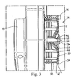
- a yarn feeder 10 comprises a housing 12 in which a motor 13 is incorporates ( Fig. 3 ).
- a yarn-winding drum 14 is keyed to the shaft 13a of motor 13.
- the yarn is wound between yarn-winding drum 14 and an adjustable sloping pin 16 which forms part of a conventional mechanism for separating the yarn loops, which is well known in the field and, accordingly, will not be further described.
- Yarn F unwinding from drum 14 passes through a tension sensor 18, which is housed within housing 12 for the feedback control of the feeder, and then is fed to a general downstream machine (not shown).
- the operative parameters of feeder 10 are managed by a push-button panel 20 provided with a display 22 ( Fig. 1 ).
- yarn-winding drum 14 comprises a molded frame 26 of a synthetic material ( Fig. 4 ), preferably a thermoplastic material such as Nylon with addition of carbon fibers.
- Frame 26 has a hub 28 and a plurality of spokes 30 spaced at equal angles, which radially project from the hub and have an aerodynamic profile in the direction of rotation.
- Spokes 30 have respective yarn-bearing arms 32 projecting from their outer ends in a direction substantially parallel to the axis of the hub, i.e., along the generatrixes of a cylinder.
- the yarn-bearing arms also have an aerodynamic profile in the direction of rotation.
- spokes 30 have a biconvex profile ( Fig.
- the profile of yarn-bearing arms 32 comprises a convex outer surface 32a and slightly concave inner surface 32b ( Fig. 7 ).
- the profiles of both spokes 30 and yarn-bearing arms 32 are symmetrical with respect to the transverse, middle lines of their respective sections.
- a projection 34 is formed in the area of connection of spoke 30 with its respective yarn-bearing arm 32.
- Projection 34 is sloping outwards at an angle ⁇ which is advantageously in the range 20° to 40°, preferably 30°, with respect to a plane perpendicular to the axis of the drum, in the direction opposite to yarn-bearing arms 32.
- a stiffening ring 36 ( Figs. 4 and 5 ) is coaxially connected to the base of frame 26, which is defined by the free ends of yarn-bearing arms 32.
- Stiffening ring 36 has a plurality of equally-spaced longitudinal holes 38 that are restrainedly engaged by respective pins 40 which longitudinally project from the free ends of yarn-bearing arms 32 ( Fig. 5 ).
- stiffening ring 36 is also made of a thermoplastic material such as Nylon with addition of carbon fibers.
- Yam winding drum 10 is keyed to shaft 13a of motor 13, with interposition of a bush insert 44 which is received in hub 28, is preferably made of aluminum, and over which the drum is molded.
- a screw 52 is screwed into bush insert 44 and engages a flattened surface 54 of shaft 13a for coupling the drum to the shaft.
- Drum 10 which essentially consists of a frame 26 made of a lightweight synthetic material with spokes 30 and yarn-bearing arms 32 interconnected by a stiffening ring 36, has a high rigidity, a low inertia, as well as a low aerodynamic drag due to spokes 30 and yarn-bearing arms 32 having respective aerodynamic profiles. This circumstance, as a person skilled in the art will immediately understand, enhances the responsiveness of yarn feeder 10 to the driving inputs.
- Projections 34 have the aim both of preventing yarn loops from slipping away from drum 10 during the feeding process, and of rewinding onto the drum any loop which, after a stop, has accidentally slipped away from the drum due to a loosening of the yarn downstream of the feeder.
- Bush insert 44 allows drum 10 to be firmly coupled to shaft 13a without deforming the drum.
- spokes 30 and yarn-bearing arms 32 may differ from those indicated as preferred, whereby any other profile having a low aerodynamic drag, e.g., a wing-like, drop-shaped profile, and the like, may be used.
- any other profile having a low aerodynamic drag e.g., a wing-like, drop-shaped profile, and the like.
- bush insert 44 may be removed if hub 28 is formed with a sturdy shape which allows screw 52 to be filmly secured without deforming the drum.
- pins 40 may be fixed to holes 38 of ring 36 in a way different from what described, e.g., they may be glued, hot riveted, laser welded, and the like; frame 26 and ring 36 could even be made enbloc.
- the materials may differ from those indicated as preferred.
- stiffening ring 36 may be made of aluminum as well as of a synthetic material different from that indicated as preferred.
Landscapes
- Engineering & Computer Science (AREA)
- Textile Engineering (AREA)
- Forwarding And Storing Of Filamentary Material (AREA)
Priority Applications (2)
| Application Number | Priority Date | Filing Date | Title |
|---|---|---|---|
| EP20090425054 EP2218670B1 (de) | 2009-02-16 | 2009-02-16 | Fadenliefervorrichtung mit einer leichten Fadenaufwickeltrommel |
| DE200960000914 DE602009000914D1 (de) | 2009-02-16 | 2009-02-16 | Fadenliefervorrichtung mit einer leichten Fadenaufwickeltrommel |
Applications Claiming Priority (1)
| Application Number | Priority Date | Filing Date | Title |
|---|---|---|---|
| EP20090425054 EP2218670B1 (de) | 2009-02-16 | 2009-02-16 | Fadenliefervorrichtung mit einer leichten Fadenaufwickeltrommel |
Publications (2)
| Publication Number | Publication Date |
|---|---|
| EP2218670A1 true EP2218670A1 (de) | 2010-08-18 |
| EP2218670B1 EP2218670B1 (de) | 2011-03-16 |
Family
ID=40809828
Family Applications (1)
| Application Number | Title | Priority Date | Filing Date |
|---|---|---|---|
| EP20090425054 Active EP2218670B1 (de) | 2009-02-16 | 2009-02-16 | Fadenliefervorrichtung mit einer leichten Fadenaufwickeltrommel |
Country Status (2)
| Country | Link |
|---|---|
| EP (1) | EP2218670B1 (de) |
| DE (1) | DE602009000914D1 (de) |
Cited By (5)
| Publication number | Priority date | Publication date | Assignee | Title |
|---|---|---|---|---|
| ITTO20120435A1 (it) * | 2012-05-17 | 2013-11-18 | Lgl Electronics Spa | Alimentatore di filato a tamburo rotante per macchine tessili. |
| EP2708625A1 (de) | 2012-09-17 | 2014-03-19 | L.G.L. Electronics S.p.A. | Fadenzufuhrgerät mit Drehtrommel für Strickverfahren mit Auswahl des Garns |
| EP2868608A1 (de) | 2013-10-29 | 2015-05-06 | L.G.L. Electronics S.p.A. | Positive Fadenzufuhrvorrichtung mit Steuerung der Zufuhrspannung |
| ITUB20160067A1 (it) * | 2016-01-26 | 2017-07-26 | Lgl Electronics Spa | Dispositivo di recupero di filato per apparati tessili. |
| CN107055197A (zh) * | 2015-10-21 | 2017-08-18 | 村田机械株式会社 | 纱线卷取装置 |
Citations (11)
| Publication number | Priority date | Publication date | Assignee | Title |
|---|---|---|---|---|
| US2175218A (en) * | 1936-06-20 | 1939-10-10 | Ind Rayon Corp | Winding reel |
| GB1453219A (en) * | 1973-11-02 | 1976-10-20 | Kanebo Ltd | Yarn feeding device for knitting machines |
| GB2158107A (en) * | 1984-05-02 | 1985-11-06 | Gustav Memminger | Yarn feeding apparatus for yarn-processing textile machines such as circular knitting machines |
| DE3437252C1 (de) * | 1984-10-11 | 1986-01-16 | Gustav 7290 Freudenstadt Memminger | Fadenspeicher- und -liefervorrichtung,insbesndere fuer Textilmaschinen |
| DE3601586C1 (de) * | 1986-01-21 | 1987-05-27 | Memminger Gmbh | Fadenspeicher- und -liefervorrichtung,insbesondere fuer Textilmaschinen |
| DE3820618A1 (de) * | 1988-06-17 | 1989-12-28 | Gustav Memminger | Fadenliefervorrichtung fuer kraeusel- oder andere effektgarne |
| US5802880A (en) * | 1997-01-10 | 1998-09-08 | Min; Lin Chung | Improvement of yarn supply reel and yarn guide for knitting machines |
| US6131842A (en) | 1998-03-14 | 2000-10-17 | Memminger-Iro Gmbh | Yarn feeder with improved yarn travel |
| DE20011831U1 (de) * | 2000-07-07 | 2000-12-28 | Chen Jen Hui | Garnzubringerrad |
| DE19932485A1 (de) * | 1999-07-12 | 2001-01-18 | Memminger Iro Gmbh | Lagereinrichtung, insbesondere für Fadenliefergeräte |
| EP1710334A1 (de) | 2005-04-06 | 2006-10-11 | L.G.L. Electronics S.p.A. | Fadenliefergerät mit positiver Fadenlieferung für Textilmaschinen |
-
2009
- 2009-02-16 EP EP20090425054 patent/EP2218670B1/de active Active
- 2009-02-16 DE DE200960000914 patent/DE602009000914D1/de active Active
Patent Citations (12)
| Publication number | Priority date | Publication date | Assignee | Title |
|---|---|---|---|---|
| US2175218A (en) * | 1936-06-20 | 1939-10-10 | Ind Rayon Corp | Winding reel |
| GB1453219A (en) * | 1973-11-02 | 1976-10-20 | Kanebo Ltd | Yarn feeding device for knitting machines |
| GB2158107A (en) * | 1984-05-02 | 1985-11-06 | Gustav Memminger | Yarn feeding apparatus for yarn-processing textile machines such as circular knitting machines |
| DE3437252C1 (de) * | 1984-10-11 | 1986-01-16 | Gustav 7290 Freudenstadt Memminger | Fadenspeicher- und -liefervorrichtung,insbesndere fuer Textilmaschinen |
| US4669677A (en) | 1984-10-11 | 1987-06-02 | Gustav Memminger | Yarn storage and delivery arrangement, particularly for textile machines |
| DE3601586C1 (de) * | 1986-01-21 | 1987-05-27 | Memminger Gmbh | Fadenspeicher- und -liefervorrichtung,insbesondere fuer Textilmaschinen |
| DE3820618A1 (de) * | 1988-06-17 | 1989-12-28 | Gustav Memminger | Fadenliefervorrichtung fuer kraeusel- oder andere effektgarne |
| US5802880A (en) * | 1997-01-10 | 1998-09-08 | Min; Lin Chung | Improvement of yarn supply reel and yarn guide for knitting machines |
| US6131842A (en) | 1998-03-14 | 2000-10-17 | Memminger-Iro Gmbh | Yarn feeder with improved yarn travel |
| DE19932485A1 (de) * | 1999-07-12 | 2001-01-18 | Memminger Iro Gmbh | Lagereinrichtung, insbesondere für Fadenliefergeräte |
| DE20011831U1 (de) * | 2000-07-07 | 2000-12-28 | Chen Jen Hui | Garnzubringerrad |
| EP1710334A1 (de) | 2005-04-06 | 2006-10-11 | L.G.L. Electronics S.p.A. | Fadenliefergerät mit positiver Fadenlieferung für Textilmaschinen |
Cited By (9)
| Publication number | Priority date | Publication date | Assignee | Title |
|---|---|---|---|---|
| ITTO20120435A1 (it) * | 2012-05-17 | 2013-11-18 | Lgl Electronics Spa | Alimentatore di filato a tamburo rotante per macchine tessili. |
| EP2664569A1 (de) | 2012-05-17 | 2013-11-20 | L.G.L. Electronics S.p.A. | Garnzuführung mit Drehtrommeln für Textilmaschinen |
| EP2708625A1 (de) | 2012-09-17 | 2014-03-19 | L.G.L. Electronics S.p.A. | Fadenzufuhrgerät mit Drehtrommel für Strickverfahren mit Auswahl des Garns |
| EP2868608A1 (de) | 2013-10-29 | 2015-05-06 | L.G.L. Electronics S.p.A. | Positive Fadenzufuhrvorrichtung mit Steuerung der Zufuhrspannung |
| CN107055197A (zh) * | 2015-10-21 | 2017-08-18 | 村田机械株式会社 | 纱线卷取装置 |
| ITUB20160067A1 (it) * | 2016-01-26 | 2017-07-26 | Lgl Electronics Spa | Dispositivo di recupero di filato per apparati tessili. |
| CN106995973A (zh) * | 2016-01-26 | 2017-08-01 | 爱吉尔电子股份公司 | 用于纺织设备的纱线回收装置 |
| EP3199680A1 (de) | 2016-01-26 | 2017-08-02 | L.G.L. Electronics S.p.A. | Garnrückgewinnungsvorrichtung für textilvorrichtungen |
| EP3199680B1 (de) | 2016-01-26 | 2020-01-15 | L.G.L. Electronics S.p.A. | Garnrückgewinnungsvorrichtung für textilvorrichtungen |
Also Published As
| Publication number | Publication date |
|---|---|
| EP2218670B1 (de) | 2011-03-16 |
| DE602009000914D1 (de) | 2011-04-28 |
Similar Documents
| Publication | Publication Date | Title |
|---|---|---|
| EP2218670B1 (de) | Fadenliefervorrichtung mit einer leichten Fadenaufwickeltrommel | |
| EP2503039B1 (de) | Positiver Garnzuführer mit Spannungsbegrenzer | |
| US10640324B2 (en) | Expandable width filament spool | |
| EP3257984B1 (de) | Garnzuführer mit motorisierter garnwickelspule | |
| CA2818037A1 (en) | Multi-spool adapter | |
| ITAR960022A1 (it) | Dispositivo per la frenatura dello svolgimento di filo metallico in matassa alloggiato in fusto | |
| SU1672928A3 (ru) | Механизм нитеподачи дл текстильных машин | |
| JP5788021B2 (ja) | 繊維強化された複合部品のチューブ状の繊維配列体を製造する方法及びチューブ状の繊維配列体 | |
| EP3594386B1 (de) | Kompensierende schussfadenbremsvorrichtung für textile anwendungen | |
| CN104846533A (zh) | 用于具有转筒的储纱馈送器的纱线退绕传感器 | |
| JPH0362818B2 (de) | ||
| RU2162816C2 (ru) | Нитеподающее устройство с улучшенным движением нити | |
| EP3575253B1 (de) | Fadenführung mit motorisierter fadenwickelspule und umspulsystem | |
| CN107460655A (zh) | 一种无需预绕线的梭芯绕线装置及缝纫机 | |
| EP3199680B1 (de) | Garnrückgewinnungsvorrichtung für textilvorrichtungen | |
| SE517500C2 (sv) | Verktyg för en rulle av ett långsträckt föremål | |
| EP2868608B1 (de) | Positive Fadenzufuhrvorrichtung mit Steuerung der Zufuhrspannung | |
| CN206720480U (zh) | 一种纺织机用纱柱 | |
| EP3945150B1 (de) | Speicherfadenzuführer mit abstandsvorrichtung zur trennung der auf die trommel gewickelten fadenschlaufen | |
| EP1624098A3 (de) | Eine Schussfadenliefervorrichtung für Webmaschinen mit einer selbsteinstellenden Fadenbremsvorrichtung | |
| JP5290723B2 (ja) | リールに使用するスプール | |
| US3334840A (en) | Head for a wire reel | |
| US7370463B2 (en) | Reel | |
| US20140091170A1 (en) | Device for repairing wire spools | |
| CN211569719U (zh) | 一种绕线装置 |
Legal Events
| Date | Code | Title | Description |
|---|---|---|---|
| PUAI | Public reference made under article 153(3) epc to a published international application that has entered the european phase |
Free format text: ORIGINAL CODE: 0009012 |
|
| 17P | Request for examination filed |
Effective date: 20090908 |
|
| AK | Designated contracting states |
Kind code of ref document: A1 Designated state(s): AT BE BG CH CY CZ DE DK EE ES FI FR GB GR HR HU IE IS IT LI LT LU LV MC MK MT NL NO PL PT RO SE SI SK TR |
|
| AX | Request for extension of the european patent |
Extension state: AL BA RS |
|
| GRAP | Despatch of communication of intention to grant a patent |
Free format text: ORIGINAL CODE: EPIDOSNIGR1 |
|
| RIC1 | Information provided on ipc code assigned before grant |
Ipc: D04B 15/48 20060101ALI20100825BHEP Ipc: B65H 51/22 20060101AFI20100825BHEP |
|
| GRAS | Grant fee paid |
Free format text: ORIGINAL CODE: EPIDOSNIGR3 |
|
| GRAA | (expected) grant |
Free format text: ORIGINAL CODE: 0009210 |
|
| AK | Designated contracting states |
Kind code of ref document: B1 Designated state(s): BE CH DE IT LI SE |
|
| REG | Reference to a national code |
Ref country code: CH Ref legal event code: EP |
|
| AKX | Designation fees paid |
Designated state(s): BE CH DE IT LI SE |
|
| REF | Corresponds to: |
Ref document number: 602009000914 Country of ref document: DE Date of ref document: 20110428 Kind code of ref document: P |
|
| REG | Reference to a national code |
Ref country code: DE Ref legal event code: R096 Ref document number: 602009000914 Country of ref document: DE Effective date: 20110428 |
|
| REG | Reference to a national code |
Ref country code: SE Ref legal event code: TRGR |
|
| PLBE | No opposition filed within time limit |
Free format text: ORIGINAL CODE: 0009261 |
|
| STAA | Information on the status of an ep patent application or granted ep patent |
Free format text: STATUS: NO OPPOSITION FILED WITHIN TIME LIMIT |
|
| 26N | No opposition filed |
Effective date: 20111219 |
|
| REG | Reference to a national code |
Ref country code: DE Ref legal event code: R097 Ref document number: 602009000914 Country of ref document: DE Effective date: 20111219 |
|
| REG | Reference to a national code |
Ref country code: CH Ref legal event code: PL |
|
| PG25 | Lapsed in a contracting state [announced via postgrant information from national office to epo] |
Ref country code: LI Free format text: LAPSE BECAUSE OF NON-PAYMENT OF DUE FEES Effective date: 20130228 Ref country code: CH Free format text: LAPSE BECAUSE OF NON-PAYMENT OF DUE FEES Effective date: 20130228 |
|
| PGFP | Annual fee paid to national office [announced via postgrant information from national office to epo] |
Ref country code: IS Payment date: 20190308 Year of fee payment: 8 |
|
| REG | Reference to a national code |
Ref country code: SE Ref legal event code: EUG |
|
| PG25 | Lapsed in a contracting state [announced via postgrant information from national office to epo] |
Ref country code: SE Free format text: LAPSE BECAUSE OF NON-PAYMENT OF DUE FEES Effective date: 20200217 |
|
| PGFP | Annual fee paid to national office [announced via postgrant information from national office to epo] |
Ref country code: IT Payment date: 20230208 Year of fee payment: 15 Ref country code: BE Payment date: 20230203 Year of fee payment: 15 |
|
| PGFP | Annual fee paid to national office [announced via postgrant information from national office to epo] |
Ref country code: DE Payment date: 20240209 Year of fee payment: 16 |