EP2218317A1 - Schleuderstreuer - Google Patents
Schleuderstreuer Download PDFInfo
- Publication number
- EP2218317A1 EP2218317A1 EP10401022A EP10401022A EP2218317A1 EP 2218317 A1 EP2218317 A1 EP 2218317A1 EP 10401022 A EP10401022 A EP 10401022A EP 10401022 A EP10401022 A EP 10401022A EP 2218317 A1 EP2218317 A1 EP 2218317A1
- Authority
- EP
- European Patent Office
- Prior art keywords
- adjusting
- centrifugal
- metering
- lever
- adjustment
- Prior art date
- Legal status (The legal status is an assumption and is not a legal conclusion. Google has not performed a legal analysis and makes no representation as to the accuracy of the status listed.)
- Granted
Links
Images


Classifications
-
- A—HUMAN NECESSITIES
- A01—AGRICULTURE; FORESTRY; ANIMAL HUSBANDRY; HUNTING; TRAPPING; FISHING
- A01C—PLANTING; SOWING; FERTILISING
- A01C17/00—Fertilisers or seeders with centrifugal wheels
- A01C17/006—Regulating or dosing devices
-
- A—HUMAN NECESSITIES
- A01—AGRICULTURE; FORESTRY; ANIMAL HUSBANDRY; HUNTING; TRAPPING; FISHING
- A01C—PLANTING; SOWING; FERTILISING
- A01C15/00—Fertiliser distributors
- A01C15/005—Undercarriages, tanks, hoppers, stirrers specially adapted for seeders or fertiliser distributors
Definitions
- the invention relates to a centrifugal spreader according to the preamble of claim 1.
- centrifugal spreader is for example by the EP 17 38 632 B1 known.
- adjusting elements for this centrifugal spreader. These adjusting elements are designed to cooperate with respect to adjusting the setting lever relative to the reservoir mounted on the trained and adjusting scale having device.
- centrifugal spreader is a guard available, but on which no adjustment scales or adjustment elements are attached, but this guard is according to the EP 17 38 632 B1 attached to the reservoir.
- the invention has for its object to provide a much simplified and easily accessible arrangement of the setting scale and the adjusting elements for adjusting at least one adjusting lever for a metering of a generic centrifugal spreader.
- a protective element for example, a guard is provided, which is seen in plan view outside the outer parts of the centrifugal discs, that the adjustment scale is arranged on the guard that the adjusting elements cooperatively formed with the guard to adjust the adjusting lever are.
- the adjustment lever can be fixed by means of the adjusting elements on the guard in the intended setting positions.
- the adjustment levers which are to be set in conjunction with the adjustment scale attached to the guard, may be designed to define the Congressneinstellposition of the metering and / or determining the position of the metering to the centrifugal disc.
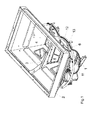
- the centrifugal spreader has a frame 1 and reservoir 2.
- the lower region of the storage container 2 is divided by a roof-shaped central part 3 into two discharge funnels 4.
- the lower ends of the outlet funnel 4 of the reservoir 2 are closed by an adjustable metering 5.
- the metering element 5 has an adjustment lever 5 in the exemplary embodiment.
- the metering element 5 in the embodiment as arranged in a bottom plate 7 outlet opening formed with an adjustable slide 8 whose opening position is determined by the adjustment lever 6.
- the materials located in the reservoir 2 are fed to an arranged below the metering element 5 rotating and with throwing blades 9, occupied centrifugal discs 10 in an adjustable manner.
- These centrifugal discs 10 are driven in rotation by a power source.
- the spreader a protective element, which is formed in the embodiment as a protective bracket 11 assigned.
- the guard bracket is seen in plan view outside the outer parts, which are formed by the throwing blades 9, the orbits described by the centrifugal discs 10.
- an adjustment scale 12 is arranged at the guard 11 . Furthermore, adjusting elements 13 are provided which cooperate with the protective bracket 11 and the adjusting lever 6 to the Adjust the adjustment lever 6 and be able to set in the desired position if necessary.
- the adjusting lever 6 can be fixed by means of the adjusting element 13 on the guard 11 in the intended setting positions.
- the adjusting device for adjusting the metering member 5 is formed accordingly, that the adjusting lever 6 in conjunction with the setting scale 12 only serves as a display element.
- only one adjusting lever 6 is provided, which cooperate by means of the attached to the protective bracket 11 setting scale 12 and cooperating with him setting elements 13.
- This adjustment lever 6 can be configured to adjust the position of the feed surface to the slinger 10 for adjusting the Mengeneinstellposition 6 of the metering 5 or fixing the metering member 5 relative to the centrifugal disc 10.
- one setting lever 6 can then be designed to determine the quantity setting of the metering element 5 and the other setting lever to fix the position of the metering element 5 to the centrifugal disk 10. This makes it possible to set and set both the application rate, as well as the position of the incident on the centrifugal disc material.
Landscapes
- Life Sciences & Earth Sciences (AREA)
- Soil Sciences (AREA)
- Environmental Sciences (AREA)
- Catching Or Destruction (AREA)
- Special Spraying Apparatus (AREA)
- Centrifugal Separators (AREA)
Abstract
Description
- Die Erfindung betrifft einen Schleuderstreuer gemäß des Oberbegriffes des Patentanspruches 1.
- Ein derartiger Schleuderstreuer ist beispielsweise durch die
EP 17 38 632 B1 bekannt geworden. Bei diesem Schleuderstreuer sind Einstellelemente vorhanden. Diese Einstellelemente sind gegenüber an dem Vorratsbehälter befestigten ausgebildeten und die Einstellskala aufweisenden Vorrichtung zusammenwirkend zur Einstellung des Einstellhebels ausgebildet. - Ein Schutzbügel ist hier bei dieser Maschine nicht vorgesehen. Bei einem entsprechend dieses bekannten Standes der Technik in der Praxis verwirklichten Schleuderstreuers ist ein Schutzbügel vorhanden, an dem aber keine Einstellskalen oder Einstellelemente befestigt sind, sondern dieser Schutzbügel ist entsprechend der
EP 17 38 632 B1 am Vorratsbehälter befestigt. - Der Erfindung liegt die Aufgabe zugrunde, eine wesentlich vereinfachte und gut zugängliche Anordnung der Einstellskala und der Einstellelemente zur Einstellung zumindest eines Einstellhebels für ein Dosierorgan eines gattungsgemäßen Schleuderstreuers zu schaffen.
- Diese Aufgabe wird erfindungsgemäß dadurch gelöst, dass ein Schutzelement, beispielsweise ein Schutzbügel vorgesehen ist, welcher sich in Draufsicht gesehen außerhalb der äußeren Teile der Schleuderscheiben befindet, dass die Einstellskala am Schutzbügel angeordnet ist, dass die Einstellelemente mit dem Schutzbügel zusammenwirkend zur Einstellung des Einstellhebels ausgebildet sind.
- Infolge dieser Maßnahmen wird in äußerst einfacher Weise eine gut zugängliche Anordnung der Einstellskala, die zu dem preiswert zu verwirklichen ist, geschaffen.
- Durch die
EP 15 04 644 B1 ist ein Schleuderstreuer bekannt, der einen Schutzbügel aufweist, der sich in Draufsicht gesehen außerhalb der äußeren Teile der Schleuderscheiben befindet. Eine Anordnung und Zuordnung von Einstellskalen und Einstellhebeln für die Dosiereinrichtung ist diesem Dokument jedoch nicht zu entnehmen. - Um in einfacher Weise den Einstellhebel in die jeweils vorgesehen Position bringen zu können und in einfacher Weise fixieren zu können, ist vorgesehen, dass der Einstellhebel mittels der Einstellelemente am Schutzbügel in den vorgesehenen Einstellpositionen festsetzbar ist.
- Die Einstellhebel, die in Zusammenhang mit der an dem Schutzbügel angebrachten Einstellskala einzustellen sind, können zur Festlegung der Mengeneinstellposition des Dosierorgans und/oder zur Festlegung der Position des Dosierorgans zur Schleuderscheibe ausgebildet sein.
- Weitere Einzelheiten der Erfindung sind der Beispielsbeschreibung und den Zeichnungen zu entnehmen. Hierbei zeigen
- Fig. 1
- den Schleuderstreuer in perspektivischer Darstellung,
- Fig. 2
- den Schleuderstreuer in anderer perspektivischer Darstellung und vergrößertem Maßstab und
- Fig. 3
- den Schleuderstreuer in perspektivischer Darstellung in der Ansicht III - III, wobei nur die linke Seite des Streuers dargestellt ist.
- Der Schleuderstreuer weist einen Rahmen 1 und Vorratsbehälter 2 auf. Der untere Bereich des Vorratsbehälters 2 ist durch ein dachförmiges Mittelteil 3 in zwei Auslauftrichter 4 aufgeteilt. Die unteren Enden der Auslauftrichter 4 des Vorratsbehälters 2 werden durch ein einstellbares Dosierelement 5 verschlossen. Das Dosierelement 5 weist im Ausführungsbeispiel einen Einstellhebel 5 auf.
- Das Dosierelement 5 im Ausführungsbeispiel als in einer Bodenplatte 7 angeordnete Auslauföffnung, die mit einem einstellbaren Schieber 8, dessen Öffnungsposition durch den Einstellhebel 6 bestimmt wird, ausgebildet. Über das Dosierelement 5 werden in einstellbarer Weise die sich im Vorratsbehälter 2 befindlichen Materialien einer unterhalb des Dosierelementes 5 angeordneten rotierend und mit Wurfschaufeln 9, besetzten Schleuderscheiben 10 zugeleitet. Diese Schleuderscheiben 10 werden von einer Kraftquelle rotierend angetrieben.
- Des Weiteren ist dem Schleuderstreuer ein Schutzelement, welches im Ausführungsbeispiel als Schutzbügel 11 ausgebildet ist, zugeordnet. Der Schützbügel befindet sich in Draufsicht gesehen außerhalb der äußeren Teile, die von den Wurfschaufeln 9 gebildet werden, der von den Schleuderscheiben 10 beschriebenen Umlaufbahnen.
- An den Schutzbügel 11 ist eine Einstellskala 12 angeordnet. Des Weiteren sind Einstellelemente 13 vorgesehen, die mit dem Schutzbügel 11 und dem Einstellhebel 6 zusammenwirken, um den Einstellhebel 6 einstellen und in vorgesehnen Positionen gegebenenfalls festsetzen zu können.
- Im Ausführungsbeispiel ist der Einstellhebel 6 mittels des Einstellelementes 13 am Schutzbügel 11 in den vorgesehenen Einstellpositionen festsetzbar. Es ist jedoch auch möglich, wenn die Einstellvorrichtung zur Einstellung des Dosierorgans 5 entsprechend ausgebildet ist, dass der Einstellhebel 6 in Verbindung mit der Einstellskala 12 nur als Anzeigeelement dient. Gemäß des Ausführungsbeispieles ist lediglich ein Einstellhebel 6 vorgesehen, der mittels der an dem Schutzbügel 11 angebrachten Einstellskala 12 und mit ihm zusammenwirkenden Einstellelementen 13 zusammenwirken. Dieser Einstellhebel 6 kann zur Einstellung der Mengeneinstellposition 6 des Dosierorgans 5 oder zur Festlegung des Dosierorgans 5 gegenüber der Schleuderscheibe 10 zur Einstellung der Lage der Aufgabefläche zur Schleuderscheibe 10 ausgebildet sein.
- Es ist in nicht dargestellter Weise auch möglich, dass mit dem Schutzbügel 11 und den dort angebrachten Anstellskalen 12 mehrere Einstellhebel 6 einstellbar und in ihrer Position gegebenenfalls feststellbar sind. Hierbei kann dann der eine Einstellhebel 6 zur Festlegung der Mengeneinstellung des Dosierorgans 5 und der andere Einstellhebel zur Festlegung der Position des Dosierorgans 5 zur Schleuderscheibe 10 ausgebildet sein. Hierdurch ist es dann möglich, sowohl die Ausbringmenge, wie auch die Position des auf die Schleuderscheibe auftreffenden Materials einzustellen und festzulegen.
Claims (5)
- Schleuderstreuer mit einem Rahmen und Vorratsbehälter, unter dem zumindest eine rotierend angetriebene Schleuderscheibe angeordnet ist, wobei der untere Bereich des Vorratsbehälters ein einstellbares Dosierelement aufweist, wobei dem Dosierelement zumindest ein Einstellhebel mit zugeordneten Einstellelementen und zumindest einer Einstellskala zugeordnet ist, wobei der Einstellhebel mit den Einstellelementen gegenüber dem Rahmen und/oder Vorratsbehälter in festlegbare Positionen einstellbar ist, dadurch gekennzeichnet, dass ein Schutzelement, beispielsweise ein Schutzbügel (11) vorgesehen ist, welcher sich in Draufsicht gesehen außerhalb der äußeren Teile (9) der Schleuderscheiben (10) befindet, dass die Einstellskala (12) am Schutzbügel (11) angeordnet ist, dass die Einstellelemente (13) mit dem Schutzbügel (11) zusammenwirkend zur Einstellung des Einstellhebels (6) ausgebildet sind.
- Schleuderstreuer nach Anspruch 1, dadurch gekennzeichnet, dass der Einstellhebel (6) mittels der Einstellelemente (13) am Schutzbügel (11) in den vorgesehenen Einstellpositionen festsetzbar ist.
- Schleuderstreuer nach Anspruch 1, dadurch gekennzeichnet, dass der Einstellhebel (6) zur Festlegung der Mengeneinstellposition des Dosierorgans (5) ausgebildet ist.
- Schleuderstreuer nach Anspruch 1, dadurch gekennzeichnet, dass der Einstellhebel (6) zur Festlegung der Position des Dosierorgans (5) zur Schleuderscheibe (10) ausgebildet ist.
- Schleuderstreuer nach Anspruch 1, dadurch gekennzeichnet, dass der Einstellhebel (6) zur Festlegung der Mengeneinstellposition des Dosierorgans (5) ausgebildet ist, dass der Einstellhebel (6) zur Festlegung der Position des Dosierorgans (5) zur Schleuderscheibe (10) ausgebildet ist.
Priority Applications (1)
| Application Number | Priority Date | Filing Date | Title |
|---|---|---|---|
| PL10401022T PL2218317T3 (pl) | 2009-02-17 | 2010-02-11 | Rozsiewacz rozpryskowy |
Applications Claiming Priority (1)
| Application Number | Priority Date | Filing Date | Title |
|---|---|---|---|
| DE102009009280A DE102009009280A1 (de) | 2009-02-17 | 2009-02-17 | Schleuderstreuer |
Publications (2)
| Publication Number | Publication Date |
|---|---|
| EP2218317A1 true EP2218317A1 (de) | 2010-08-18 |
| EP2218317B1 EP2218317B1 (de) | 2011-11-23 |
Family
ID=42173167
Family Applications (1)
| Application Number | Title | Priority Date | Filing Date |
|---|---|---|---|
| EP10401022A Not-in-force EP2218317B1 (de) | 2009-02-17 | 2010-02-11 | Schleuderstreuer |
Country Status (4)
| Country | Link |
|---|---|
| EP (1) | EP2218317B1 (de) |
| AT (1) | ATE534277T1 (de) |
| DE (1) | DE102009009280A1 (de) |
| PL (1) | PL2218317T3 (de) |
Citations (4)
| Publication number | Priority date | Publication date | Assignee | Title |
|---|---|---|---|---|
| DE1582032A1 (de) * | 1962-09-25 | 1969-10-02 | Lely Nv C Van Der | Streuvorrichtung fuer koerniges oder pulverfoermiges Gut |
| EP0410312A1 (de) * | 1989-07-22 | 1991-01-30 | Rauch Landmaschinenfabrik Gmbh | Scheuderstreuer für rieselfähiges Streugut, insbesondere Dünger |
| EP0857409A1 (de) * | 1997-02-11 | 1998-08-12 | Maasland N.V. | Düngerstreuer |
| EP1902607A1 (de) * | 2006-09-22 | 2008-03-26 | Rauch Landmaschinenfabrik Gmbh | Schleuderstreuer für Streugut |
Family Cites Families (2)
| Publication number | Priority date | Publication date | Assignee | Title |
|---|---|---|---|---|
| DE10335765A1 (de) | 2003-08-05 | 2005-03-03 | Amazonen-Werke H. Dreyer Gmbh & Co. Kg | Schleuderdüngerstreuer |
| DE102005030781B4 (de) | 2005-07-01 | 2018-05-30 | Rauch Landmaschinenfabrik Gmbh | Schleuderstreuer für Streugut |
-
2009
- 2009-02-17 DE DE102009009280A patent/DE102009009280A1/de not_active Withdrawn
-
2010
- 2010-02-11 PL PL10401022T patent/PL2218317T3/pl unknown
- 2010-02-11 EP EP10401022A patent/EP2218317B1/de not_active Not-in-force
- 2010-02-11 AT AT10401022T patent/ATE534277T1/de active
Patent Citations (4)
| Publication number | Priority date | Publication date | Assignee | Title |
|---|---|---|---|---|
| DE1582032A1 (de) * | 1962-09-25 | 1969-10-02 | Lely Nv C Van Der | Streuvorrichtung fuer koerniges oder pulverfoermiges Gut |
| EP0410312A1 (de) * | 1989-07-22 | 1991-01-30 | Rauch Landmaschinenfabrik Gmbh | Scheuderstreuer für rieselfähiges Streugut, insbesondere Dünger |
| EP0857409A1 (de) * | 1997-02-11 | 1998-08-12 | Maasland N.V. | Düngerstreuer |
| EP1902607A1 (de) * | 2006-09-22 | 2008-03-26 | Rauch Landmaschinenfabrik Gmbh | Schleuderstreuer für Streugut |
Also Published As
| Publication number | Publication date |
|---|---|
| PL2218317T3 (pl) | 2012-04-30 |
| EP2218317B1 (de) | 2011-11-23 |
| ATE534277T1 (de) | 2011-12-15 |
| DE102009009280A1 (de) | 2010-08-19 |
Similar Documents
| Publication | Publication Date | Title |
|---|---|---|
| DE102011088512B3 (de) | Spreuaufbereitungs- und -verteilvorrichtung | |
| EP2832202A1 (de) | Sämaschine | |
| EP2039233A1 (de) | Zentraldosierer | |
| EP1738632B1 (de) | Schleuderstreuer für Streugut | |
| EP3610714B1 (de) | Einzelkornsäaggregat | |
| EP2218317B1 (de) | Schleuderstreuer | |
| DE3537426A1 (de) | Kombinationswaage | |
| EP3228167B1 (de) | Säschar | |
| DE102008013162A1 (de) | Sämaschine | |
| EP0951814B1 (de) | Schleuderdüngerstreuer | |
| EP1078564B1 (de) | Schleuderdüngerstreuer | |
| EP2404494B1 (de) | Dosiereinrichtung | |
| EP2489251A1 (de) | Pneumatischer Dosierer | |
| EP2311303B1 (de) | Schleuderstreuer | |
| EP2574224B1 (de) | Vorratsbehälter mit einer siebartigen Abdeck- und Schutzeinrichtung | |
| EP2314143B1 (de) | Schleuderstreuer | |
| DE102008020020A1 (de) | Zentrifugalstreuer | |
| DE102012112367A1 (de) | Streugerät | |
| EP2522208B1 (de) | Pneumatische Verteilmaschine | |
| EP2508059B1 (de) | Verteilmaschine | |
| EP2510769A1 (de) | Pneumatische Einzelkornsämaschine | |
| DE102015101035A1 (de) | Sämaschine | |
| DE102017116453B3 (de) | Landwirtschaftliche Verteilmaschine | |
| DE10033674A1 (de) | Schleuderdüngerstreuer | |
| EP2364583A1 (de) | Landwirtschaftliche Verteilmaschine |
Legal Events
| Date | Code | Title | Description |
|---|---|---|---|
| PUAI | Public reference made under article 153(3) epc to a published international application that has entered the european phase |
Free format text: ORIGINAL CODE: 0009012 |
|
| AK | Designated contracting states |
Kind code of ref document: A1 Designated state(s): AT BE BG CH CY CZ DE DK EE ES FI FR GB GR HR HU IE IS IT LI LT LU LV MC MK MT NL NO PL PT RO SE SI SK SM TR |
|
| AX | Request for extension of the european patent |
Extension state: AL BA RS |
|
| 17P | Request for examination filed |
Effective date: 20101022 |
|
| RIC1 | Information provided on ipc code assigned before grant |
Ipc: A01C 17/00 20060101ALI20110531BHEP Ipc: A01C 15/00 20060101AFI20110531BHEP |
|
| GRAP | Despatch of communication of intention to grant a patent |
Free format text: ORIGINAL CODE: EPIDOSNIGR1 |
|
| GRAS | Grant fee paid |
Free format text: ORIGINAL CODE: EPIDOSNIGR3 |
|
| GRAA | (expected) grant |
Free format text: ORIGINAL CODE: 0009210 |
|
| AK | Designated contracting states |
Kind code of ref document: B1 Designated state(s): AT BE BG CH CY CZ DE DK EE ES FI FR GB GR HR HU IE IS IT LI LT LU LV MC MK MT NL NO PL PT RO SE SI SK SM TR |
|
| REG | Reference to a national code |
Ref country code: GB Ref legal event code: FG4D Free format text: NOT ENGLISH |
|
| REG | Reference to a national code |
Ref country code: CH Ref legal event code: EP |
|
| REG | Reference to a national code |
Ref country code: IE Ref legal event code: FG4D Free format text: LANGUAGE OF EP DOCUMENT: GERMAN |
|
| REG | Reference to a national code |
Ref country code: DE Ref legal event code: R096 Ref document number: 502010000244 Country of ref document: DE Effective date: 20120216 |
|
| REG | Reference to a national code |
Ref country code: NL Ref legal event code: VDEP Effective date: 20111123 |
|
| LTIE | Lt: invalidation of european patent or patent extension |
Effective date: 20111123 |
|
| PG25 | Lapsed in a contracting state [announced via postgrant information from national office to epo] |
Ref country code: LT Free format text: LAPSE BECAUSE OF FAILURE TO SUBMIT A TRANSLATION OF THE DESCRIPTION OR TO PAY THE FEE WITHIN THE PRESCRIBED TIME-LIMIT Effective date: 20111123 Ref country code: IS Free format text: LAPSE BECAUSE OF FAILURE TO SUBMIT A TRANSLATION OF THE DESCRIPTION OR TO PAY THE FEE WITHIN THE PRESCRIBED TIME-LIMIT Effective date: 20120323 Ref country code: NO Free format text: LAPSE BECAUSE OF FAILURE TO SUBMIT A TRANSLATION OF THE DESCRIPTION OR TO PAY THE FEE WITHIN THE PRESCRIBED TIME-LIMIT Effective date: 20120223 |
|
| REG | Reference to a national code |
Ref country code: PL Ref legal event code: T3 |
|
| PG25 | Lapsed in a contracting state [announced via postgrant information from national office to epo] |
Ref country code: GR Free format text: LAPSE BECAUSE OF FAILURE TO SUBMIT A TRANSLATION OF THE DESCRIPTION OR TO PAY THE FEE WITHIN THE PRESCRIBED TIME-LIMIT Effective date: 20120224 Ref country code: LV Free format text: LAPSE BECAUSE OF FAILURE TO SUBMIT A TRANSLATION OF THE DESCRIPTION OR TO PAY THE FEE WITHIN THE PRESCRIBED TIME-LIMIT Effective date: 20111123 Ref country code: HR Free format text: LAPSE BECAUSE OF FAILURE TO SUBMIT A TRANSLATION OF THE DESCRIPTION OR TO PAY THE FEE WITHIN THE PRESCRIBED TIME-LIMIT Effective date: 20111123 Ref country code: SI Free format text: LAPSE BECAUSE OF FAILURE TO SUBMIT A TRANSLATION OF THE DESCRIPTION OR TO PAY THE FEE WITHIN THE PRESCRIBED TIME-LIMIT Effective date: 20111123 Ref country code: NL Free format text: LAPSE BECAUSE OF FAILURE TO SUBMIT A TRANSLATION OF THE DESCRIPTION OR TO PAY THE FEE WITHIN THE PRESCRIBED TIME-LIMIT Effective date: 20111123 Ref country code: SE Free format text: LAPSE BECAUSE OF FAILURE TO SUBMIT A TRANSLATION OF THE DESCRIPTION OR TO PAY THE FEE WITHIN THE PRESCRIBED TIME-LIMIT Effective date: 20111123 Ref country code: PT Free format text: LAPSE BECAUSE OF FAILURE TO SUBMIT A TRANSLATION OF THE DESCRIPTION OR TO PAY THE FEE WITHIN THE PRESCRIBED TIME-LIMIT Effective date: 20120323 |
|
| REG | Reference to a national code |
Ref country code: IE Ref legal event code: FD4D |
|
| PG25 | Lapsed in a contracting state [announced via postgrant information from national office to epo] |
Ref country code: CY Free format text: LAPSE BECAUSE OF FAILURE TO SUBMIT A TRANSLATION OF THE DESCRIPTION OR TO PAY THE FEE WITHIN THE PRESCRIBED TIME-LIMIT Effective date: 20111123 |
|
| PG25 | Lapsed in a contracting state [announced via postgrant information from national office to epo] |
Ref country code: CZ Free format text: LAPSE BECAUSE OF FAILURE TO SUBMIT A TRANSLATION OF THE DESCRIPTION OR TO PAY THE FEE WITHIN THE PRESCRIBED TIME-LIMIT Effective date: 20111123 Ref country code: EE Free format text: LAPSE BECAUSE OF FAILURE TO SUBMIT A TRANSLATION OF THE DESCRIPTION OR TO PAY THE FEE WITHIN THE PRESCRIBED TIME-LIMIT Effective date: 20111123 Ref country code: SK Free format text: LAPSE BECAUSE OF FAILURE TO SUBMIT A TRANSLATION OF THE DESCRIPTION OR TO PAY THE FEE WITHIN THE PRESCRIBED TIME-LIMIT Effective date: 20111123 Ref country code: DK Free format text: LAPSE BECAUSE OF FAILURE TO SUBMIT A TRANSLATION OF THE DESCRIPTION OR TO PAY THE FEE WITHIN THE PRESCRIBED TIME-LIMIT Effective date: 20111123 Ref country code: IE Free format text: LAPSE BECAUSE OF FAILURE TO SUBMIT A TRANSLATION OF THE DESCRIPTION OR TO PAY THE FEE WITHIN THE PRESCRIBED TIME-LIMIT Effective date: 20111123 Ref country code: BG Free format text: LAPSE BECAUSE OF FAILURE TO SUBMIT A TRANSLATION OF THE DESCRIPTION OR TO PAY THE FEE WITHIN THE PRESCRIBED TIME-LIMIT Effective date: 20120223 |
|
| BERE | Be: lapsed |
Owner name: AMAZONEN-WERKE H. DREYER G.M.B.H. & CO. KG Effective date: 20120228 |
|
| PG25 | Lapsed in a contracting state [announced via postgrant information from national office to epo] |
Ref country code: RO Free format text: LAPSE BECAUSE OF FAILURE TO SUBMIT A TRANSLATION OF THE DESCRIPTION OR TO PAY THE FEE WITHIN THE PRESCRIBED TIME-LIMIT Effective date: 20111123 |
|
| PG25 | Lapsed in a contracting state [announced via postgrant information from national office to epo] |
Ref country code: MC Free format text: LAPSE BECAUSE OF NON-PAYMENT OF DUE FEES Effective date: 20120229 |
|
| PLBE | No opposition filed within time limit |
Free format text: ORIGINAL CODE: 0009261 |
|
| STAA | Information on the status of an ep patent application or granted ep patent |
Free format text: STATUS: NO OPPOSITION FILED WITHIN TIME LIMIT |
|
| 26N | No opposition filed |
Effective date: 20120824 |
|
| REG | Reference to a national code |
Ref country code: DE Ref legal event code: R097 Ref document number: 502010000244 Country of ref document: DE Effective date: 20120824 |
|
| PG25 | Lapsed in a contracting state [announced via postgrant information from national office to epo] |
Ref country code: BE Free format text: LAPSE BECAUSE OF NON-PAYMENT OF DUE FEES Effective date: 20120228 |
|
| PG25 | Lapsed in a contracting state [announced via postgrant information from national office to epo] |
Ref country code: MK Free format text: LAPSE BECAUSE OF FAILURE TO SUBMIT A TRANSLATION OF THE DESCRIPTION OR TO PAY THE FEE WITHIN THE PRESCRIBED TIME-LIMIT Effective date: 20111123 |
|
| PG25 | Lapsed in a contracting state [announced via postgrant information from national office to epo] |
Ref country code: ES Free format text: LAPSE BECAUSE OF FAILURE TO SUBMIT A TRANSLATION OF THE DESCRIPTION OR TO PAY THE FEE WITHIN THE PRESCRIBED TIME-LIMIT Effective date: 20120305 |
|
| PG25 | Lapsed in a contracting state [announced via postgrant information from national office to epo] |
Ref country code: FI Free format text: LAPSE BECAUSE OF FAILURE TO SUBMIT A TRANSLATION OF THE DESCRIPTION OR TO PAY THE FEE WITHIN THE PRESCRIBED TIME-LIMIT Effective date: 20111123 |
|
| PG25 | Lapsed in a contracting state [announced via postgrant information from national office to epo] |
Ref country code: MT Free format text: LAPSE BECAUSE OF FAILURE TO SUBMIT A TRANSLATION OF THE DESCRIPTION OR TO PAY THE FEE WITHIN THE PRESCRIBED TIME-LIMIT Effective date: 20111123 |
|
| PG25 | Lapsed in a contracting state [announced via postgrant information from national office to epo] |
Ref country code: TR Free format text: LAPSE BECAUSE OF FAILURE TO SUBMIT A TRANSLATION OF THE DESCRIPTION OR TO PAY THE FEE WITHIN THE PRESCRIBED TIME-LIMIT Effective date: 20111123 |
|
| PG25 | Lapsed in a contracting state [announced via postgrant information from national office to epo] |
Ref country code: SM Free format text: LAPSE BECAUSE OF FAILURE TO SUBMIT A TRANSLATION OF THE DESCRIPTION OR TO PAY THE FEE WITHIN THE PRESCRIBED TIME-LIMIT Effective date: 20111123 Ref country code: LU Free format text: LAPSE BECAUSE OF NON-PAYMENT OF DUE FEES Effective date: 20120211 |
|
| PG25 | Lapsed in a contracting state [announced via postgrant information from national office to epo] |
Ref country code: HU Free format text: LAPSE BECAUSE OF FAILURE TO SUBMIT A TRANSLATION OF THE DESCRIPTION OR TO PAY THE FEE WITHIN THE PRESCRIBED TIME-LIMIT Effective date: 20100211 |
|
| REG | Reference to a national code |
Ref country code: CH Ref legal event code: PL |
|
| GBPC | Gb: european patent ceased through non-payment of renewal fee |
Effective date: 20140211 |
|
| PG25 | Lapsed in a contracting state [announced via postgrant information from national office to epo] |
Ref country code: LI Free format text: LAPSE BECAUSE OF NON-PAYMENT OF DUE FEES Effective date: 20140228 Ref country code: CH Free format text: LAPSE BECAUSE OF NON-PAYMENT OF DUE FEES Effective date: 20140228 |
|
| PG25 | Lapsed in a contracting state [announced via postgrant information from national office to epo] |
Ref country code: GB Free format text: LAPSE BECAUSE OF NON-PAYMENT OF DUE FEES Effective date: 20140211 |
|
| REG | Reference to a national code |
Ref country code: FR Ref legal event code: PLFP Year of fee payment: 7 |
|
| PGFP | Annual fee paid to national office [announced via postgrant information from national office to epo] |
Ref country code: PL Payment date: 20151216 Year of fee payment: 7 |
|
| REG | Reference to a national code |
Ref country code: AT Ref legal event code: MM01 Ref document number: 534277 Country of ref document: AT Kind code of ref document: T Effective date: 20150211 |
|
| PGFP | Annual fee paid to national office [announced via postgrant information from national office to epo] |
Ref country code: IT Payment date: 20160222 Year of fee payment: 7 Ref country code: DE Payment date: 20160202 Year of fee payment: 7 |
|
| PG25 | Lapsed in a contracting state [announced via postgrant information from national office to epo] |
Ref country code: AT Free format text: LAPSE BECAUSE OF NON-PAYMENT OF DUE FEES Effective date: 20150211 |
|
| PGFP | Annual fee paid to national office [announced via postgrant information from national office to epo] |
Ref country code: FR Payment date: 20160108 Year of fee payment: 7 |
|
| REG | Reference to a national code |
Ref country code: DE Ref legal event code: R119 Ref document number: 502010000244 Country of ref document: DE |
|
| REG | Reference to a national code |
Ref country code: FR Ref legal event code: ST Effective date: 20171031 |
|
| PG25 | Lapsed in a contracting state [announced via postgrant information from national office to epo] |
Ref country code: FR Free format text: LAPSE BECAUSE OF NON-PAYMENT OF DUE FEES Effective date: 20170228 Ref country code: DE Free format text: LAPSE BECAUSE OF NON-PAYMENT OF DUE FEES Effective date: 20170901 |
|
| PG25 | Lapsed in a contracting state [announced via postgrant information from national office to epo] |
Ref country code: IT Free format text: LAPSE BECAUSE OF NON-PAYMENT OF DUE FEES Effective date: 20170211 |
|
| PG25 | Lapsed in a contracting state [announced via postgrant information from national office to epo] |
Ref country code: PL Free format text: LAPSE BECAUSE OF NON-PAYMENT OF DUE FEES Effective date: 20170211 |