EP2217915B1 - Titration device and method - Google Patents
Titration device and method Download PDFInfo
- Publication number
- EP2217915B1 EP2217915B1 EP08858643.3A EP08858643A EP2217915B1 EP 2217915 B1 EP2217915 B1 EP 2217915B1 EP 08858643 A EP08858643 A EP 08858643A EP 2217915 B1 EP2217915 B1 EP 2217915B1
- Authority
- EP
- European Patent Office
- Prior art keywords
- titration
- reservoir
- electrode
- ion source
- titrant
- Prior art date
- Legal status (The legal status is an assumption and is not a legal conclusion. Google has not performed a legal analysis and makes no representation as to the accuracy of the status listed.)
- Active
Links
- 238000004448 titration Methods 0.000 title claims description 86
- 238000000034 method Methods 0.000 title claims description 21
- 150000002500 ions Chemical class 0.000 claims description 64
- 239000000523 sample Substances 0.000 claims description 51
- 239000002253 acid Substances 0.000 claims description 35
- 230000008384 membrane barrier Effects 0.000 claims description 30
- 239000012488 sample solution Substances 0.000 claims description 26
- 239000003014 ion exchange membrane Substances 0.000 claims description 17
- 239000007788 liquid Substances 0.000 claims description 15
- 229910052709 silver Inorganic materials 0.000 claims description 15
- 239000004332 silver Substances 0.000 claims description 15
- 238000004891 communication Methods 0.000 claims description 8
- 230000000903 blocking effect Effects 0.000 claims description 7
- 238000001514 detection method Methods 0.000 claims description 7
- 238000003756 stirring Methods 0.000 claims description 4
- 239000002585 base Substances 0.000 description 31
- 239000000243 solution Substances 0.000 description 26
- HEMHJVSKTPXQMS-UHFFFAOYSA-M Sodium hydroxide Chemical compound [OH-].[Na+] HEMHJVSKTPXQMS-UHFFFAOYSA-M 0.000 description 21
- 239000012528 membrane Substances 0.000 description 21
- BASFCYQUMIYNBI-UHFFFAOYSA-N platinum Chemical compound [Pt] BASFCYQUMIYNBI-UHFFFAOYSA-N 0.000 description 14
- -1 silver-silver halide Chemical class 0.000 description 14
- 239000003792 electrolyte Substances 0.000 description 9
- 239000003480 eluent Substances 0.000 description 9
- BQCADISMDOOEFD-UHFFFAOYSA-N Silver Chemical compound [Ag] BQCADISMDOOEFD-UHFFFAOYSA-N 0.000 description 8
- 150000001768 cations Chemical class 0.000 description 8
- 230000004888 barrier function Effects 0.000 description 7
- 238000005443 coulometric titration Methods 0.000 description 7
- XLYOFNOQVPJJNP-UHFFFAOYSA-N water Substances O XLYOFNOQVPJJNP-UHFFFAOYSA-N 0.000 description 7
- AFVFQIVMOAPDHO-UHFFFAOYSA-N Methanesulfonic acid Chemical compound CS(O)(=O)=O AFVFQIVMOAPDHO-UHFFFAOYSA-N 0.000 description 6
- 238000005341 cation exchange Methods 0.000 description 6
- 239000012141 concentrate Substances 0.000 description 5
- 229910052697 platinum Inorganic materials 0.000 description 5
- 150000003839 salts Chemical class 0.000 description 5
- 239000012491 analyte Substances 0.000 description 4
- 150000001450 anions Chemical class 0.000 description 4
- 239000007864 aqueous solution Substances 0.000 description 4
- 238000006243 chemical reaction Methods 0.000 description 4
- 239000003153 chemical reaction reagent Substances 0.000 description 4
- 238000009792 diffusion process Methods 0.000 description 4
- 238000005868 electrolysis reaction Methods 0.000 description 4
- 239000000463 material Substances 0.000 description 4
- VEXZGXHMUGYJMC-UHFFFAOYSA-M Chloride anion Chemical compound [Cl-] VEXZGXHMUGYJMC-UHFFFAOYSA-M 0.000 description 3
- 239000004809 Teflon Substances 0.000 description 3
- 229920006362 Teflon® Polymers 0.000 description 3
- 238000004458 analytical method Methods 0.000 description 3
- 239000003011 anion exchange membrane Substances 0.000 description 3
- 238000000429 assembly Methods 0.000 description 3
- 230000000712 assembly Effects 0.000 description 3
- 230000015572 biosynthetic process Effects 0.000 description 3
- 230000008859 change Effects 0.000 description 3
- 239000007789 gas Substances 0.000 description 3
- XLYOFNOQVPJJNP-UHFFFAOYSA-M hydroxide Chemical compound [OH-] XLYOFNOQVPJJNP-UHFFFAOYSA-M 0.000 description 3
- 238000004255 ion exchange chromatography Methods 0.000 description 3
- 238000012544 monitoring process Methods 0.000 description 3
- 238000006386 neutralization reaction Methods 0.000 description 3
- 239000002243 precursor Substances 0.000 description 3
- 230000004044 response Effects 0.000 description 3
- NWUYHJFMYQTDRP-UHFFFAOYSA-N 1,2-bis(ethenyl)benzene;1-ethenyl-2-ethylbenzene;styrene Chemical compound C=CC1=CC=CC=C1.CCC1=CC=CC=C1C=C.C=CC1=CC=CC=C1C=C NWUYHJFMYQTDRP-UHFFFAOYSA-N 0.000 description 2
- HNSDLXPSAYFUHK-UHFFFAOYSA-N 1,4-bis(2-ethylhexyl) sulfosuccinate Chemical compound CCCCC(CC)COC(=O)CC(S(O)(=O)=O)C(=O)OCC(CC)CCCC HNSDLXPSAYFUHK-UHFFFAOYSA-N 0.000 description 2
- CURLTUGMZLYLDI-UHFFFAOYSA-N Carbon dioxide Chemical compound O=C=O CURLTUGMZLYLDI-UHFFFAOYSA-N 0.000 description 2
- BVKZGUZCCUSVTD-UHFFFAOYSA-L Carbonate Chemical compound [O-]C([O-])=O BVKZGUZCCUSVTD-UHFFFAOYSA-L 0.000 description 2
- XFXPMWWXUTWYJX-UHFFFAOYSA-N Cyanide Chemical compound N#[C-] XFXPMWWXUTWYJX-UHFFFAOYSA-N 0.000 description 2
- VEXZGXHMUGYJMC-UHFFFAOYSA-N Hydrochloric acid Chemical compound Cl VEXZGXHMUGYJMC-UHFFFAOYSA-N 0.000 description 2
- KDLHZDBZIXYQEI-UHFFFAOYSA-N Palladium Chemical compound [Pd] KDLHZDBZIXYQEI-UHFFFAOYSA-N 0.000 description 2
- 229910021607 Silver chloride Inorganic materials 0.000 description 2
- PMZURENOXWZQFD-UHFFFAOYSA-L Sodium Sulfate Chemical compound [Na+].[Na+].[O-]S([O-])(=O)=O PMZURENOXWZQFD-UHFFFAOYSA-L 0.000 description 2
- QAOWNCQODCNURD-UHFFFAOYSA-N Sulfuric acid Chemical compound OS(O)(=O)=O QAOWNCQODCNURD-UHFFFAOYSA-N 0.000 description 2
- 229910052946 acanthite Inorganic materials 0.000 description 2
- 150000007513 acids Chemical class 0.000 description 2
- 238000013459 approach Methods 0.000 description 2
- 238000011109 contamination Methods 0.000 description 2
- 238000003869 coulometry Methods 0.000 description 2
- 230000000694 effects Effects 0.000 description 2
- 230000002401 inhibitory effect Effects 0.000 description 2
- 239000011159 matrix material Substances 0.000 description 2
- 238000005259 measurement Methods 0.000 description 2
- QSHDDOUJBYECFT-UHFFFAOYSA-N mercury Chemical compound [Hg] QSHDDOUJBYECFT-UHFFFAOYSA-N 0.000 description 2
- 229910052753 mercury Inorganic materials 0.000 description 2
- 229940098779 methanesulfonic acid Drugs 0.000 description 2
- 229910000510 noble metal Inorganic materials 0.000 description 2
- KJFMBFZCATUALV-UHFFFAOYSA-N phenolphthalein Chemical compound C1=CC(O)=CC=C1C1(C=2C=CC(O)=CC=2)C2=CC=CC=C2C(=O)O1 KJFMBFZCATUALV-UHFFFAOYSA-N 0.000 description 2
- 230000010287 polarization Effects 0.000 description 2
- 238000002360 preparation method Methods 0.000 description 2
- 230000008569 process Effects 0.000 description 2
- 239000012266 salt solution Substances 0.000 description 2
- 239000012898 sample dilution Substances 0.000 description 2
- 238000007789 sealing Methods 0.000 description 2
- XUARKZBEFFVFRG-UHFFFAOYSA-N silver sulfide Chemical compound [S-2].[Ag+].[Ag+] XUARKZBEFFVFRG-UHFFFAOYSA-N 0.000 description 2
- 229940056910 silver sulfide Drugs 0.000 description 2
- 229910001415 sodium ion Inorganic materials 0.000 description 2
- 229910052938 sodium sulfate Inorganic materials 0.000 description 2
- 235000011152 sodium sulphate Nutrition 0.000 description 2
- 239000000126 substance Substances 0.000 description 2
- 239000003115 supporting electrolyte Substances 0.000 description 2
- 238000003221 volumetric titration Methods 0.000 description 2
- 241000270728 Alligator Species 0.000 description 1
- 229910000497 Amalgam Inorganic materials 0.000 description 1
- CWYNVVGOOAEACU-UHFFFAOYSA-N Fe2+ Chemical compound [Fe+2] CWYNVVGOOAEACU-UHFFFAOYSA-N 0.000 description 1
- VTLYFUHAOXGGBS-UHFFFAOYSA-N Fe3+ Chemical compound [Fe+3] VTLYFUHAOXGGBS-UHFFFAOYSA-N 0.000 description 1
- DGAQECJNVWCQMB-PUAWFVPOSA-M Ilexoside XXIX Chemical compound C[C@@H]1CC[C@@]2(CC[C@@]3(C(=CC[C@H]4[C@]3(CC[C@@H]5[C@@]4(CC[C@@H](C5(C)C)OS(=O)(=O)[O-])C)C)[C@@H]2[C@]1(C)O)C)C(=O)O[C@H]6[C@@H]([C@H]([C@@H]([C@H](O6)CO)O)O)O.[Na+] DGAQECJNVWCQMB-PUAWFVPOSA-M 0.000 description 1
- 229910002651 NO3 Inorganic materials 0.000 description 1
- NHNBFGGVMKEFGY-UHFFFAOYSA-N Nitrate Chemical compound [O-][N+]([O-])=O NHNBFGGVMKEFGY-UHFFFAOYSA-N 0.000 description 1
- 239000004696 Poly ether ether ketone Substances 0.000 description 1
- FOIXSVOLVBLSDH-UHFFFAOYSA-N Silver ion Chemical compound [Ag+] FOIXSVOLVBLSDH-UHFFFAOYSA-N 0.000 description 1
- FKNQFGJONOIPTF-UHFFFAOYSA-N Sodium cation Chemical compound [Na+] FKNQFGJONOIPTF-UHFFFAOYSA-N 0.000 description 1
- 239000003513 alkali Substances 0.000 description 1
- 230000008901 benefit Effects 0.000 description 1
- JUPQTSLXMOCDHR-UHFFFAOYSA-N benzene-1,4-diol;bis(4-fluorophenyl)methanone Chemical compound OC1=CC=C(O)C=C1.C1=CC(F)=CC=C1C(=O)C1=CC=C(F)C=C1 JUPQTSLXMOCDHR-UHFFFAOYSA-N 0.000 description 1
- 229910001423 beryllium ion Inorganic materials 0.000 description 1
- 230000005540 biological transmission Effects 0.000 description 1
- 239000008280 blood Substances 0.000 description 1
- 210000004369 blood Anatomy 0.000 description 1
- 239000001569 carbon dioxide Substances 0.000 description 1
- 229910002092 carbon dioxide Inorganic materials 0.000 description 1
- 230000015556 catabolic process Effects 0.000 description 1
- 239000003729 cation exchange resin Substances 0.000 description 1
- 239000003795 chemical substances by application Substances 0.000 description 1
- 238000004587 chromatography analysis Methods 0.000 description 1
- 230000001276 controlling effect Effects 0.000 description 1
- 238000006731 degradation reaction Methods 0.000 description 1
- 230000005684 electric field Effects 0.000 description 1
- 238000000909 electrodialysis Methods 0.000 description 1
- 239000008151 electrolyte solution Substances 0.000 description 1
- 229940021013 electrolyte solution Drugs 0.000 description 1
- 238000002474 experimental method Methods 0.000 description 1
- 230000008713 feedback mechanism Effects 0.000 description 1
- 238000004442 gravimetric analysis Methods 0.000 description 1
- GPRLSGONYQIRFK-UHFFFAOYSA-N hydron Chemical compound [H+] GPRLSGONYQIRFK-UHFFFAOYSA-N 0.000 description 1
- 230000003993 interaction Effects 0.000 description 1
- 239000003456 ion exchange resin Substances 0.000 description 1
- 229920003303 ion-exchange polymer Polymers 0.000 description 1
- 229910052741 iridium Inorganic materials 0.000 description 1
- GKOZUEZYRPOHIO-UHFFFAOYSA-N iridium atom Chemical compound [Ir] GKOZUEZYRPOHIO-UHFFFAOYSA-N 0.000 description 1
- 230000007774 longterm Effects 0.000 description 1
- 238000000691 measurement method Methods 0.000 description 1
- 230000007246 mechanism Effects 0.000 description 1
- 229910052751 metal Inorganic materials 0.000 description 1
- 239000002184 metal Substances 0.000 description 1
- 238000012986 modification Methods 0.000 description 1
- 230000004048 modification Effects 0.000 description 1
- 230000003472 neutralizing effect Effects 0.000 description 1
- 230000003647 oxidation Effects 0.000 description 1
- 238000007254 oxidation reaction Methods 0.000 description 1
- XLYOFNOQVPJJNP-UHFFFAOYSA-O oxonium Chemical compound [OH3+] XLYOFNOQVPJJNP-UHFFFAOYSA-O 0.000 description 1
- 229910052763 palladium Inorganic materials 0.000 description 1
- 239000004033 plastic Substances 0.000 description 1
- 229920002530 polyetherether ketone Polymers 0.000 description 1
- 239000000376 reactant Substances 0.000 description 1
- 230000009467 reduction Effects 0.000 description 1
- 230000001105 regulatory effect Effects 0.000 description 1
- 238000012552 review Methods 0.000 description 1
- 238000007086 side reaction Methods 0.000 description 1
- HKZLPVFGJNLROG-UHFFFAOYSA-M silver monochloride Chemical compound [Cl-].[Ag+] HKZLPVFGJNLROG-UHFFFAOYSA-M 0.000 description 1
- 229910052708 sodium Inorganic materials 0.000 description 1
- 239000011734 sodium Substances 0.000 description 1
- 241000894007 species Species 0.000 description 1
- 239000011550 stock solution Substances 0.000 description 1
- 230000007704 transition Effects 0.000 description 1
- 230000001960 triggered effect Effects 0.000 description 1
Images

Classifications
-
- G—PHYSICS
- G01—MEASURING; TESTING
- G01N—INVESTIGATING OR ANALYSING MATERIALS BY DETERMINING THEIR CHEMICAL OR PHYSICAL PROPERTIES
- G01N31/00—Investigating or analysing non-biological materials by the use of the chemical methods specified in the subgroup; Apparatus specially adapted for such methods
- G01N31/16—Investigating or analysing non-biological materials by the use of the chemical methods specified in the subgroup; Apparatus specially adapted for such methods using titration
- G01N31/162—Determining the equivalent point by means of a discontinuity
- G01N31/164—Determining the equivalent point by means of a discontinuity by electrical or electrochemical means
Definitions
- the present invention relates to a titration device and method and, more particularly to one using electrolytic titrant generation.
- Determining the total acidity or alkalinity of a sample is now a routine part of characterizing a sample in many industrial laboratories.
- a simple way to pursue this measurement uses a volumetric titration apparatus including a volumetric burette from which the appropriate titrant, usually acid or base titrant, is added to a stirred sample while monitoring sample characteristics such as pH or conductivity. From the characteristic plot of detector response versus volume of the titrant and the associated endpoint, the equivalents of acid or base in a given sample is determined.
- the field of titration is over 100 years old, and there is significant literature covering various aspects of titration.
- There are also several books in basic analytical chemistry that cover the basic aspects of titration theory and the determination of the end point (For example Chapter 3 entitled Gravimetric and Volumetric Analysis, Analytical Chemistry HandBook, by John A. Dean, McGraw Hill Inc, 1995 ).
- Modern titrators use an automated means of dispensing the liquid titrant, for example, by using a motorized syringe.
- the dispensing of the titrant is done in a constant mode with each increment having a constant volume or in a dynamic mode where the titrant is added in large aliquots and near the end point the addition frequency is reduced to get an accurate determination of the end point.
- the dynamic mode expedites the analysis and reduces the analysis time.
- modem titrators still use liquid titrant reagents that need to be frequently prepared and replenished to ensure no degradation or build up of contamination. For example titration with a base titrant results in a carbonate error with an indicator with a basic transition point (phenolphthalein). For basic titrants proper precautions during preparation and storage needs to be taken.
- Coulometry is an established methodology in the field of titration. Typically, in volumetric titration the volume of liquid titrant required to neutralize the acid or base in a sample is measured. In a coulometric titration the titrant is generated electrochemically and the quantity of electric charge is measured. Coulometry titration could be classified as primary and secondary titration. In the primary titration methods the titrant is directly derived from the electrode. Examples of this type of electrodes are silver metal, mercury, or mercury amalgam or electrodes coated with silver-silver halide and they generate the ions required for the titration for example silver metal anode forming silver ions that can be used to titrate chloride.
- Secondary titration methods are much more popular and use an intermediate ion generated from a precursor that is added to the supporting electrolyte.
- the intermediate ions must be generated with 100% current efficiency and must react rapidly and stoichiometrically with the substance being determined. For example during the coulometric titration of Fe(II) to Fe (III), the method will not be 100% current efficient unless excess Ce (III) is added as the precursor to the supporting electrolyte sulfuric acid.
- the current in a coulometric titration is usually maintained constant and by monitoring the time in seconds, the number of coulombs required to titrate a species and hence the number of equivalents is easily derived. Detection of the end point of the titration occurs via conventional means such as color change from addition of an indicator. Other means such as using an amperometric, pH or conductivity detection is also routinely used.
- US Patent 2,744,061 discloses a titration apparatus in which the reagent is prepared in a separate cell from the titration cell and the reagent is then introduced into the titration vessel.
- Such a scheme produces acid and base from electrolysis of 1 M sodium sulfate solution and one or the other stream could be introduced for titration.
- the method suffers from a) sample dilution errors b) need to control the flow of the sodium sulfate feed c) addition of salt solution to the sample since not all of the electrolyte was used for the formation of acid or base and this would limit the detection to detectors that are sensitive to the presence of salt.
- conductivity detectors cannot be used in the above scheme because the conductivity of the 1 M salt solution will overwhelm the detector response making it difficult to detect small changes in conductivity from the presence of small amounts of acid or base.
- US Patent 3,856,633 discloses a concentration measurement technique that uses coulometrically generated silver ions from a silver anode and a platinum cathode in the presence of sample cyanide ions.
- Silver ions react with the cyanide ions lowering the free silver ion availability which is then monitored across a silver sulfide membrane by a potential measurement.
- the free silver ions unreacted with the sample are on one side of the membrane, and a standard with a known quantity of silver ions is on the other side of the membrane. From the developed potential a detection scheme was available for the sample ions.
- the silver sulfide membrane was placed between the silver anode and the platinum cathode to protect the silver anode from exposure to reactive species such as nitrate in the sample.
- US Patent 4,007,105 discloses a titration apparatus for coulometric titration of chloride in blood samples that uses a silver anode and a platinum cathode in an acid electrolyte medium.
- the silver ions generated in proportional to an applied current reacts with the chloride in the sample forming silver chloride and the titration is monitored using a pair of amperometric electrodes. Also disclosed is the arrangement of the electrode cells.
- flash titration a version of this approach where only a portion of the sample stream in the vicinity of the electrode is titrated significantly reduced the overall titration time. Since the methodology is a diffusion regulated process, the method is sensitive to varying diffusion rates of various sample acids and bases, temperature and sample viscosity. A calibration step called the matrix adjustment factor is needed to compensate for the above effects.
- WO 99/38595 describes a method and apparatus for generating an acid or base, e.g., for chromatographic analysis of ions.
- a cation source such as a salt, cation hydroxide or cation exchange resin
- a permselective barrier For generating a base, a cation source, such as a salt, cation hydroxide or cation exchange resin, is provided in a cation reservoir separated from a base generation chamber by a permselective barrier.
- An aqueous stream flows through the base generation chamber containing a cation exchange material.
- An electric potential is applied between an anode in the cation source reservoir and a cathode in the base generation chamber to electrolytically generate hydroxide ions and cause cations in the reservoir to electromigrate through the barrier toward the cathode to combine with the migrated cations to form cation hydroxide, which flows from the base generation chamber.
- WO 97/18503 describes a device for the amperometric adjustment of an ion concentration in solution has at least three chamber-like electrolyte regions, each of which has a control electrode and diffusion-inhibiting means and can be filled with electrolytes. All electrolyte regions can be brought into contact with the solution in such a way that when current flows through the control electrodes, ions from the electrolyte solutions can be transported via the diffusion-inhibiting means into the adjustment solution or vice versa.
- the device also comprises means for supplying each electrolyte region with control currents.
- the device is set up to regulate the pH value and/or an ion concentration of the solution which differs from the hydrogen ion concentration. At least two and if necessary all of the electrolyte regions are secured together by securing means.
- electrolysis is employed for raising or reducing pH of culture solution.
- Electrolyte contained in a vessel having at least one ion exchange membrane as a wall is provided so as to confront the culture solution, with the ion exchange membrane lying therebetween.
- Electrodes are provided both in the electrolyte and the culture solution. With these electrodes the electrolysis is carried out through the ion exchange membrane.
- formed alkali or acid changes the pH of the culture solution.
- EP 1,685,887 relates to ion chromatography analysis, more specifically to devices for producing an eluent for ion chromatography.
- the electrodialysis eluent generator for ion chromatography comprises an ion source container, an eluent generating chamber which is provided with input and output ports, an ion-exchange membrane which is arranged between the ion source container and the eluent generating chamber, an aqueous solution source connected to the input port of the eluent generating chamber, a first electrode arranged in the ion source container and a second electrode which is arranged in the eluent generating chamber and embodied in the form of an ion-exchange membrane provided with an electroconductive layer applied to the surface thereof.
- Said membrane is used as the external wall of the eluent generating chamber, said electroconductive layer being applied to the external, with respect to the eluent generating chamber, side of the ion-exchange membrane.
- Said generator also comprises a current power supply.
- a titration apparatus comprising a titration reservoir for a non-flowing sample solution to be titrated; an ion source reservoir comprising an ion source solution of selected ions, positive or negative; an ion exchange membrane barrier capable of passing ions of one charge, positive or negative, from said ion source solution to said titration reservoir, but of blocking bulk liquid flow; a first electrode in electrical communication with said ion source reservoir; and a second electrode in electrical communication with said ion source reservoir, said first electrode being inert when a current is applied between said first and second electrodes, said second electrode contacting said membrane barrier.
- an electrolytic titrant generator for use in a titration apparatus, comprising an ion source reservoir; a first electrode disposed in said ion source reservoir; an ion exchange membrane barrier having first and second sides, the first side being adjacent to said ion source reservoir and capable of transporting ions of one charge, positive or negative, but of blocking bulk liquid flow, and a second electrode disposed adjacent to the second side of the membrane barrier, said second electrode contacting said membrane barrier, said titrant generator not including a titration reservoir for sample solution to be titrated but being configured to be immersed in sample solution in a titration reservoir.
- an electrolytic method for titrating a liquid sample using a titration apparatus of the foregoing type comprises applying an electrical potential between the first and second electrodes to cause the selected ions to be transported from an ion source reservoir through the membrane barrier into sample solution in the titration reservoir to titrate the sample solution to an end point, the first electrode being inert during application of the potential, and detecting the titration end point.
- the invention includes the embodiments of an electrolytic titrant generator, a titration device which incorporates an electrolytic titrant generator, and a method of titrating using such a device.
- the invention will first be described with respect to the titrant generator.
- the titrant generator may be in the form of a portable device which can be mounted to a titration reservoir which typically includes a non-flowing sample solution to be titrated.
- the titrant generator operates as follows. Ions are transported into the titration reservoir of sample solution from an ion source solution in a separate chamber of the generator through an ion exchange membrane barrier. A first electrode is disposed in the ion source reservoir and a second electrode is disposed adjacent to the other side of the membrane barrier from the ion source reservoir.
- the titrant generator may be separate from the titration reservoir but is configured to be immersed in the sample solution. Thus, it is small enough to be immersed in the sample solution of a titration reservoir.
- titrant generator is assembly 28 illustrated in the exploded schematic view of Figure 1 . It includes an ion source reservoir or container 12 which is filled with a source of selective positive or negative ions 26. Such source may be an aqueous solution of an acid, base, or salt or may be ion exchange resin with exchangeable ions of the selected ions.
- An electrode 16 is mounted to project into the ion source in container 12 in electrical contact therewith. As illustrated, electrode 16 is mounted to an optional container cover 14 which encloses container 12 and routes the electrical connections for electrode 16.
- a gas vent may be included for container 12, such as in cover 14, to remove electrically generated gases from the container.
- a membrane barrier 20, which may comprise one, two, three, or more ion exchange membranes, is mounted across container 12 in sealing engagement therewith near the container bottom. As illustrated, assembly 28 is in cylindrical form. Thus, the ion exchange membranes of barrier 20, three in number as illustrated, are in a stacked disc configuration.
- Membrane barrier 20 substantially blocks flow of liquid.
- substantially blocking means blocking all flow except a small amount of liquid leakage. Preferably, essentially all bulk liquid flow is blocked.
- the barrier could be a single ion exchange membrane or one or more ion exchange membranes could be used as the barrier.
- the number of membranes in the barrier is less than 10, more preferably less than 7 and most preferably less than about 4, specifically 1-3 membranes. The rationale for having multiple membranes is to minimize leakage of the ion source solution into the sample and to substantially block sample flow back into the ion source solution.
- Electrode 24 is disposed near the bottom of generator 28 for contact with sample solution in a titration reservoir adjacent to membrane barrier 20 on the opposite side of the membrane from container 12.
- An enclosure 10 with an opening 10A (not shown) is used to hold electrode 24 and ion exchange membrane barrier 20.
- Enclosure 10 is sealed to container 12 using an "O" ring seal 22 which may be formed of an inert plastic material, such as Teflon, using an appropriate mounting mechanism such as male machine threads 18.
- enclosure 10 has internal (female) threads which mate with male threads 18 on the bottom of container 12 to enclose seal 22, membrane barrier 20, and electrode 24 to make a leak-free seal.
- Opening 10A termed an output cavity, is fitted with electrode 24 for exposure to the sample solution in a titration reservoir.
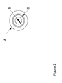
- Figure 2 shows a top view of enclosure 10.
- the outer diameter of the enclosure is designated A; the internal opening of the output cavity 10A fitted with the electrode and the membranes is designated “B”; and the sealing surface on which the "O" ring seal is mounted to seal with a lower portion of the ion source reservoir container 12 is designated “C”.
- Container 12 of assembly 28 is filled with the ion source solution through an inlet in lid 14 or by removing the lid.
- Electrode 24 at the bottom of the assembly is in open contact with a sample solution in a titration reservoir when immersed therein as part of a complete titration apparatus.
- Generator assembly 28 may be mounted, directly or indirectly to a titration reservoir, preferably in an orientation so that the exposed surface of electrode 24 is immersed in the titration solution.
- electrode 24 is substantially planar with one of its planar surfaces proximal to membrane barrier 20 and its surface distal to the membrane barrier exposed for direct contact with the titration solution.
- a large portion of this distal surface of electrode 24 is exposed to the environment so that when it is immersed in a titration reservoir of solution to be titrated, a large surface area of electrode 24 is available for the transmission of electrodes through the membrane and electrode.
- a removable cover may be placed over the electrode to protect it for shipment or the like which is removed prior to use during titration.
- the titrant generator may be in a form other than a cylinder, such as one having a rectangular cross-section.
- electrode 24 need not be of the same cross-section and orientation as membrane barrier 20 so long as it is an electrical communication with the membrane when immersed in the titrant solution.
- membrane barrier 20 contacts electrode 24.
- membrane barrier 20 may be in direct contact with the titrant solution.
- the electrodes and the membranes in any shape or configuration preferably closely match the output cavity in the titration device. It is desirable that the output cavity have a small delay volume thereby eliminating any issues with sweep out from the cavity. If the delay volume is too large then it may be difficult to remove the generated titrant and disperse it into the sample.
- the output cavity is of the same dimension as the exposed electrode area to the sample.
- the electrode surface area expressed as a percentage of the open output cavity is referably in the range of 5-100%, more preferably at least 50% or 80% and most preferably about 100%.
- electrodes 16 and 24 are inert to acid or base when a potential is applied across them.
- inert excludes the materials that would be substantially degraded under the electrolytic conditions of titration and electrodes which would serve as the source of the selected titration ions.
- the preferred inert electrodes exclude silver electrodes used as a source of silver ions in the prior art.
- Preferred inert materials for electrodes include noble metals such as platinum, palladium, iridium and the like.
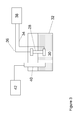
- FIG 3 illustrates a titration device according to the present invention which includes a titrant generator assembly 28 as described in Figure 1 .
- the titrant generator component may be in the form of the described portable generator which is suitably mounted to the titration tank by a clamp or the like.
- the titrant generator may be a non-portable component constructed and directly mounted to project into the tank.
- titration reservoir 32 is illustrated including an aqueous sample solution 30 to be titrated.
- solution 30 is substantially non-flowing during titration.
- a stir bar with a stirrer may be used for mixing the sample so that the titrant is mixed efficiently with the sample to neutralize the sample.
- stirred solution is considered non-flowing.
- the titrant generator 28 is of the type illustrated in Figure 1 . It is powered using a DC power supply 38 connected by electrical lines 34 and 36.
- a detector probe 40 e.g. a pH or conductivity probe, is installed to project into the solution in reservoir 32 to monitor the progress of the titration.
- Detector probe 40 is connected to an appropriate detector 42 such as a pH or conductivity detector.
- container 12 is filled with a cation source that would supply the cations required for the base formation.
- a cation source that would supply the cations required for the base formation.
- the source could be a source of sodium, such as an aqueous solution sodium hydroxide concentrate.
- the electrodes 16 and 24, not sources of the titrant ions, are made from inert metal platinum foil. Electrode 16 is designated in this embodiment as the anode.
- the enclosure 10 is fitted with a platinum foil 24 which is designated as a cathode, followed by three layers of cation exchange membrane 20.
- the Teflon "O" ring 22 is installed next and the enclosure 10 is fitted on to the conduit 12.
- Electrode 24 is exposed at the bottom of the assembly. Electrode 24 is available for water splitting reactions and for titrant generation. For generating anions for an acid titrant, all polarities are reversed, the titrant generator assembly 28 is assembled with anion exchange membrane, and the container 12 is filled with an anion source that would supply the anions required for the acid formation.
- Electrode 24 is in contact with the sample solution 30. Upon applying a potential large enough to split water, hydronium ions are generated at the anode 16 while hydroxide ions are generated at the cathode 24 by the water splitting reactions at the electrode surfaces.
- the water required for the water splitting reaction at the cathode is derived from the sample solution.
- the sodium ions are driven from the container 12 through the cation exchange membrane barrier 20 and combine with the hydroxide generated at the cathode to form sodium hydroxide titrant.
- the sodium hydroxide titrant is now dispersed in the sample for neutralization of acids in the sample. No substantial change in the sample volume is observed.
- For each hydroxide generated at the cathode one sodium ion is transported into the sample solution.
- the hydronium ion generated at the anode is consumed in neutralizing the base in the source container. Over time, the base in the source container is depleted and is converted to a more dilute form. By monitoring the voltage across the container, the source ions could be replenished.
- the volume of the ion source container 12 is suitably from about 1 ml to 2000 ml; more preferably from 5 ml to 1000 ml and most preferably from about 10 ml to about 400 ml.
- the concentration of the source when using a liquid source would preferably be less than 10 M, more preferably less than about 4 M, and most preferably less than about 2 M.
- the applied current for titrant generation is preferably less than about 2 A more preferably less than about 400 mA and most preferably less than about 100 mA.
- the ion source container could be replenished when needed in an automated manner using known methods.
- the present invention overcomes limitations of coulometric titrations such as (a) a need for electrode derived reagents since the current method uses inert noble metals for purely water splitting reactions; (b) a need to add precursor for generation of intermediate ions; and (c) a need to pursue matrix factor adjustment as mandated by flash titration method.
- the base titrant generator of the present invention when combined with the acid generator of the present invention could generate both acid and base titrants on demand.
- the titrant devices thus could allow back titration applications.
- the titrator generators are two separate devices. It is also possible to integrate the two devices to have one source container such as a salt and form the acid or base from the anion or cation of the source form of the salt.
- the device would be a "H" shaped device with the two vertical components comprising of two titrant assemblies 28 which have anion exchange membranes for acid generation and cation exchange membranes for base generation respectively with appropriate polarity of the electrodes as discussed previously.
- the horizontal "H” portion would be a conduit connecting the acid and base assemblies 28 so there is fluidic communication between the two vertical sections.
- the electrodes 24 and 16 of the respective assemblies would be powered to create acid or base titrant in response to the applied current, as the case may be.
- Example 1 Base titrant generator: A 9 x 100 mm chromatographic column PEEK hardware from Dionex Corporation was used in this example. The end fitting detail is shown in Figure 2 . These modifications allowed electrode and membrane stack to be assembled as shown in Figure 1 . A Teflon "O" Ring was used to make the final seal against the 9 x 100 mm conduit or container. The electrode was made from a perforated platinum foil of 0.001" thickness and was cut in the shape of a circle with a diameter of 0.5". The cation exchange membrane CMI 7000 was obtained from Membrane International, Inc. (Glen Rock, New Jersey) and cut in the shape of a circle with a diameter of 0.5". Three pieces of the membrane was used in the above assembly.
- An anode was a rectangular piece of a platinum electrode (1 x 6") that was placed in the 9 x 50 mm column as shown in Figure 1 .
- the electrodes were connected using platinum wire and then connected using normal leads with alligator clips to a DC power supply (HP).
- a 2 M NaOH solution was prepared from a stock solution of 50 % NaOH (Sigma Aldrich, St. Louis, MO) and was used as the source concentrate in the 9 x 100 mm column.
- Example 2 The titrant generator from Example 1 was placed in a sample container (50 ml beaker) and was oriented in the vertical direction roughly above 2 " from the bottom of the container using a clamp.
- a pH probe (A EG50 Combination pH/Ag-AgCl electrode from Dionex Corporation, Sunnyvale, CA) was used as the probe to monitor the progress of the titration.
- the output from the pH meter was plotted as mV signal.
- a sample containing 20 mM Methane sulfonic acid was prepared accurately from a stock concentrate of Methane sulfonic acid (Sigma Aldrich Chemicals, St. Louis, MO) and 15 ml of the prepared acid was added to the sample container.
- the titrant generator was powered at 50 mA constant current conditions.
- the setup was similar to what is shown in Figure 2 .
- a stir bar was placed in the container and the solution was stirred using a stirring plate.
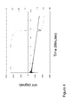
- the theoretical equivalence point is calculated as 9.660 minutes.
- a plot of the monitored potential versus time and the derivative plot showed the equivalence point to be very close to the theoretical number and were estimated to be 9.667 minutes as shown in Figure 4 . This shows excellent correlation between the theory and practical observation. This also validates the utility of the titrant generator as per the present invention.
- Example 3 The device of Example 1 was tested at 200 mA generating a high concentration of titrant.(124 ⁇ eqv/min).. The device was able to titrate successfully 600 ⁇ eqv of acid as shown in Table 1.
- Table 1 Sample Sample Conc mM Sample Volume mL Current mA Expected Time (Min) Observed Time (Min) HCl 60 10 200 4.83 4.81 HCl 10 10 40 4.03 4.07 MSA 10 10 40 4.03 4.09
- the device voltage was monitored and when the device voltage increased by 10 V the source concentrate was replenished.
- the device was also tested with other samples and conditions as listed in Table 1.
- the setup was semi automated in that the start time was triggered manually. Good correlation between theory and experiment was realized.
- Example 4 Acid titrant generator: The hardware from example 1 was used for assembling the acid generator as per the present invention. All aspects of the assembly were similar to example 1 except anion exchange membranes AMI 7001 from Membrane International, Inc. (Glen Rock, New Jersey) were used in place of the cation exchange membranes. A 2 M Methane sulfonic acid solution was prepared from the concentrated acid obtained from Sigma Aldrich, St. Louis, MO and was used as the source concentrate in the 9 x 100 mm column. The polarity of the electrodes was reversed with the electrode in contact with the sample being the anode and the electrode in contact with the acid source being a cathode. The device is now suitable for acid generation.
- anion exchange membranes AMI 7001 from Membrane International, Inc. (Glen Rock, New Jersey) were used in place of the cation exchange membranes.
- a 2 M Methane sulfonic acid solution was prepared from the concentrated acid obtained from Sigma Aldrich, St. Louis, MO and was used as
- Example 5 A sample comprising of 20 mM NaOH x 5 mL or 100 ⁇ eqv was added to a sample container as before and was tested with the acid generator of example 4. Approximately 20 mL of DI water was added to ensure that the acid generator and the pH probe were fully immersed in the sample container. The setup was tested at a current of 50 mA which corresponded to roughly 31 ⁇ eqv of acid and was used to neutralize the base. The expected time for completion of neutralization was 3.22 minutes and the observed time was 3.24 minutes suggesting excellent correlation with theory.
Landscapes
- Health & Medical Sciences (AREA)
- Chemical & Material Sciences (AREA)
- Life Sciences & Earth Sciences (AREA)
- Physics & Mathematics (AREA)
- Electrochemistry (AREA)
- Molecular Biology (AREA)
- Chemical Kinetics & Catalysis (AREA)
- Analytical Chemistry (AREA)
- Biochemistry (AREA)
- General Health & Medical Sciences (AREA)
- General Physics & Mathematics (AREA)
- Immunology (AREA)
- Pathology (AREA)
- Investigating Or Analyzing Non-Biological Materials By The Use Of Chemical Means (AREA)
Applications Claiming Priority (2)
| Application Number | Priority Date | Filing Date | Title |
|---|---|---|---|
| US11/952,013 US8475639B2 (en) | 2007-12-06 | 2007-12-06 | Titration device and method |
| PCT/US2008/085466 WO2009076144A1 (en) | 2007-12-06 | 2008-12-04 | Titration device and method |
Publications (2)
| Publication Number | Publication Date |
|---|---|
| EP2217915A1 EP2217915A1 (en) | 2010-08-18 |
| EP2217915B1 true EP2217915B1 (en) | 2015-10-14 |
Family
ID=40404148
Family Applications (1)
| Application Number | Title | Priority Date | Filing Date |
|---|---|---|---|
| EP08858643.3A Active EP2217915B1 (en) | 2007-12-06 | 2008-12-04 | Titration device and method |
Country Status (4)
| Country | Link |
|---|---|
| US (1) | US8475639B2 (cg-RX-API-DMAC7.html) |
| EP (1) | EP2217915B1 (cg-RX-API-DMAC7.html) |
| JP (1) | JP5686602B2 (cg-RX-API-DMAC7.html) |
| WO (1) | WO2009076144A1 (cg-RX-API-DMAC7.html) |
Families Citing this family (9)
| Publication number | Priority date | Publication date | Assignee | Title |
|---|---|---|---|---|
| WO2012051466A1 (en) * | 2010-10-14 | 2012-04-19 | Sportsman Consulting Llc | Analytical method and titration device |
| JP5643605B2 (ja) * | 2010-10-27 | 2014-12-17 | サントリーホールディングス株式会社 | 測定装置および測定方法 |
| EP2773221B1 (en) | 2011-11-04 | 2019-01-09 | Bio-Rad Laboratories, Inc. | Simultaneous purification of cell components |
| US9766207B2 (en) | 2011-11-04 | 2017-09-19 | Bio-Rad Laboratories, Inc. | Affinity methods and compositions employing electronic control of pH |
| EP2814597A4 (en) | 2012-02-15 | 2015-10-28 | Bio Rad Laboratories | ELECTRONIC CONTROL OF PH-VALUE AND ION STRENGTH |
| US9321012B2 (en) | 2012-04-04 | 2016-04-26 | Bio-Rad Laboratories, Inc. | Electronic protein fractionation |
| EP2840390A1 (de) | 2013-08-19 | 2015-02-25 | Mettler-Toledo AG | Coulometrische Titrationszelle |
| US11029280B2 (en) * | 2016-06-23 | 2021-06-08 | Hach Company | Alkalinity sensor |
| US11714059B2 (en) * | 2020-12-23 | 2023-08-01 | Hach Company | Isolating interferences in alkalinity measurement |
Family Cites Families (16)
| Publication number | Priority date | Publication date | Assignee | Title |
|---|---|---|---|---|
| US2744061A (en) | 1951-04-16 | 1956-05-01 | Research Corp | Coulometric titration |
| US2954336A (en) | 1957-07-30 | 1960-09-27 | Standard Oil Co | Universal titrating agent generator |
| NL259614A (cg-RX-API-DMAC7.html) | 1959-12-31 | |||
| US3308041A (en) | 1961-12-05 | 1967-03-07 | Beckman Instruments Inc | Method and apparatus for titration |
| US3374161A (en) * | 1964-10-28 | 1968-03-19 | Beckman Instruments Inc | External coulometric generator |
| US3856633A (en) | 1971-01-07 | 1974-12-24 | Foxboro Co | Concentration measurements utilizing coulometric generation of reagents |
| US4007105A (en) | 1975-07-11 | 1977-02-08 | Beckman Instruments, Inc. | Electrode module for titration apparatus |
| JPS5362637A (en) | 1976-11-12 | 1978-06-05 | Matsushita Electric Industrial Co Ltd | Automatic controlling method and device for ph of culture solution |
| JPS61241663A (ja) * | 1985-04-19 | 1986-10-27 | Mitsui Petrochem Ind Ltd | ヒドロペルオキシドの連続定量法 |
| JPH03216543A (ja) * | 1990-01-23 | 1991-09-24 | Nippon Hyomen Kagaku Kk | 過酸化水素濃度測定装置 |
| US5045204A (en) | 1990-02-13 | 1991-09-03 | Dionex Corporation | Method and apparatus for generating a high purity chromatography eluent |
| JPH0635950U (ja) * | 1992-10-13 | 1994-05-13 | 住友金属工業株式会社 | 鋼材の硫化水素試験装置 |
| JP2000501173A (ja) | 1995-11-14 | 2000-02-02 | フーア、ギュンター | イオン濃度を調整するための装置および方法 |
| US6225129B1 (en) * | 1998-02-02 | 2001-05-01 | Dionex Corporation | Large capacity acid or base generation apparatus and method of use |
| US7402283B2 (en) | 2002-09-11 | 2008-07-22 | Dionex Corporation | Electrolytic eluent generator and method of use |
| RU2229325C1 (ru) | 2003-11-12 | 2004-05-27 | ЗАО "Научно-Производственная Коммерческая Фирма Аквилон" | Электродиализный генератор элюента для ионной хроматографии |
-
2007
- 2007-12-06 US US11/952,013 patent/US8475639B2/en active Active
-
2008
- 2008-12-04 EP EP08858643.3A patent/EP2217915B1/en active Active
- 2008-12-04 WO PCT/US2008/085466 patent/WO2009076144A1/en not_active Ceased
- 2008-12-04 JP JP2010537040A patent/JP5686602B2/ja not_active Expired - Fee Related
Non-Patent Citations (1)
| Title |
|---|
| W. OELSSNER ET AL: "The iR drop - well-known but often underestimated in electrochemical polarization measurements and corrosion testing", MATERIALS AND CORROSION/WERKSTOFFE UND KORROSION, vol. 57, no. 6, 1 June 2006 (2006-06-01), pages 455 - 466, XP055064318, ISSN: 0947-5117, DOI: 10.1002/maco.200603982 * |
Also Published As
| Publication number | Publication date |
|---|---|
| JP5686602B2 (ja) | 2015-03-18 |
| US8475639B2 (en) | 2013-07-02 |
| EP2217915A1 (en) | 2010-08-18 |
| WO2009076144A1 (en) | 2009-06-18 |
| JP2011506930A (ja) | 2011-03-03 |
| US20090145777A1 (en) | 2009-06-11 |
Similar Documents
| Publication | Publication Date | Title |
|---|---|---|
| EP2217915B1 (en) | Titration device and method | |
| JP3499872B2 (ja) | 電気化学反応における又は電気化学反応に関する改良 | |
| US10871464B2 (en) | Ion-selective electrode, method of manufacture thereof, and cartridge | |
| EP2995940B1 (en) | Karl fischer titrator and karl fischer titration method | |
| JP2002503330A (ja) | 微小燃料電池酸素ガス・センサ | |
| JP5832453B2 (ja) | 液体クロマトグラフィーシステム用の電気化学的検出セル | |
| JPS6222424B2 (cg-RX-API-DMAC7.html) | ||
| EP0992792A2 (en) | Fluid analyte measurement system | |
| Bhakthavatsalam et al. | Selective coulometric release of ions from ion selective polymeric membranes for calibration-free titrations | |
| US10254246B2 (en) | Method and apparatus for measuring and controlling electrolytically-active species concentration in aqueous solutions | |
| Vanýsek | Electrolysis with electrolyte dropping electrode: Part III. Investigation of anions | |
| US5334295A (en) | Micro fuel-cell oxygen gas sensor | |
| US4960497A (en) | Apparatus and method for minimizing the effect of an electrolyte's dissolved oxygen content in low range oxygen analyzers | |
| EP4357774B1 (en) | Electrolytic device noise reduction and lifetime improvement using modulated driver | |
| US10352896B2 (en) | Coulometric titration cell | |
| US5041202A (en) | Apparatus for the continuous production of a standard ionic solution | |
| US3764508A (en) | Electrochemical oxygen demand measuring system | |
| JPH08145944A (ja) | Codの電気分析方法およびcod測定装置 | |
| Bogeski et al. | Experiments towards understanding binding potential of hydroxilated CoQ's lipophilic forms to earth-alkaline cations | |
| Gulaboski | Square-wave Voltammetry of Surface Electrode Mechanisms with Non-Unity Stoichiometry-Simulation Protocol in MATHCAD | |
| JPS6055778B2 (ja) | 血清から鉄を解放するための組成物 | |
| Gulaboski et al. | Calculating Theoretical Square-wave voltammograms of a diffusional catalytic EC'mechanism-MATHCAD working file for performing simulations | |
| JPS61126460A (ja) | 電量分析法 | |
| Kitatsuji | Electroanalytical Study of Actinide Ions | |
| Gordon et al. | Electrochemical techniques |
Legal Events
| Date | Code | Title | Description |
|---|---|---|---|
| PUAI | Public reference made under article 153(3) epc to a published international application that has entered the european phase |
Free format text: ORIGINAL CODE: 0009012 |
|
| 17P | Request for examination filed |
Effective date: 20100527 |
|
| AK | Designated contracting states |
Kind code of ref document: A1 Designated state(s): AT BE BG CH CY CZ DE DK EE ES FI FR GB GR HR HU IE IS IT LI LT LU LV MC MT NL NO PL PT RO SE SI SK TR |
|
| AX | Request for extension of the european patent |
Extension state: AL BA MK RS |
|
| DAX | Request for extension of the european patent (deleted) | ||
| 17Q | First examination report despatched |
Effective date: 20130603 |
|
| GRAP | Despatch of communication of intention to grant a patent |
Free format text: ORIGINAL CODE: EPIDOSNIGR1 |
|
| INTG | Intention to grant announced |
Effective date: 20150508 |
|
| GRAS | Grant fee paid |
Free format text: ORIGINAL CODE: EPIDOSNIGR3 |
|
| GRAA | (expected) grant |
Free format text: ORIGINAL CODE: 0009210 |
|
| AK | Designated contracting states |
Kind code of ref document: B1 Designated state(s): AT BE BG CH CY CZ DE DK EE ES FI FR GB GR HR HU IE IS IT LI LT LU LV MC MT NL NO PL PT RO SE SI SK TR |
|
| REG | Reference to a national code |
Ref country code: GB Ref legal event code: FG4D |
|
| REG | Reference to a national code |
Ref country code: AT Ref legal event code: REF Ref document number: 755519 Country of ref document: AT Kind code of ref document: T Effective date: 20151015 Ref country code: CH Ref legal event code: EP |
|
| REG | Reference to a national code |
Ref country code: IE Ref legal event code: FG4D |
|
| REG | Reference to a national code |
Ref country code: DE Ref legal event code: R096 Ref document number: 602008040710 Country of ref document: DE |
|
| REG | Reference to a national code |
Ref country code: NL Ref legal event code: MP Effective date: 20151014 |
|
| REG | Reference to a national code |
Ref country code: LT Ref legal event code: MG4D |
|
| REG | Reference to a national code |
Ref country code: AT Ref legal event code: MK05 Ref document number: 755519 Country of ref document: AT Kind code of ref document: T Effective date: 20151014 |
|
| PG25 | Lapsed in a contracting state [announced via postgrant information from national office to epo] |
Ref country code: HR Free format text: LAPSE BECAUSE OF FAILURE TO SUBMIT A TRANSLATION OF THE DESCRIPTION OR TO PAY THE FEE WITHIN THE PRESCRIBED TIME-LIMIT Effective date: 20151014 Ref country code: IS Free format text: LAPSE BECAUSE OF FAILURE TO SUBMIT A TRANSLATION OF THE DESCRIPTION OR TO PAY THE FEE WITHIN THE PRESCRIBED TIME-LIMIT Effective date: 20160214 Ref country code: ES Free format text: LAPSE BECAUSE OF FAILURE TO SUBMIT A TRANSLATION OF THE DESCRIPTION OR TO PAY THE FEE WITHIN THE PRESCRIBED TIME-LIMIT Effective date: 20151014 Ref country code: NL Free format text: LAPSE BECAUSE OF FAILURE TO SUBMIT A TRANSLATION OF THE DESCRIPTION OR TO PAY THE FEE WITHIN THE PRESCRIBED TIME-LIMIT Effective date: 20151014 Ref country code: LT Free format text: LAPSE BECAUSE OF FAILURE TO SUBMIT A TRANSLATION OF THE DESCRIPTION OR TO PAY THE FEE WITHIN THE PRESCRIBED TIME-LIMIT Effective date: 20151014 Ref country code: IT Free format text: LAPSE BECAUSE OF FAILURE TO SUBMIT A TRANSLATION OF THE DESCRIPTION OR TO PAY THE FEE WITHIN THE PRESCRIBED TIME-LIMIT Effective date: 20151014 Ref country code: NO Free format text: LAPSE BECAUSE OF FAILURE TO SUBMIT A TRANSLATION OF THE DESCRIPTION OR TO PAY THE FEE WITHIN THE PRESCRIBED TIME-LIMIT Effective date: 20160114 |
|
| PG25 | Lapsed in a contracting state [announced via postgrant information from national office to epo] |
Ref country code: AT Free format text: LAPSE BECAUSE OF FAILURE TO SUBMIT A TRANSLATION OF THE DESCRIPTION OR TO PAY THE FEE WITHIN THE PRESCRIBED TIME-LIMIT Effective date: 20151014 Ref country code: PL Free format text: LAPSE BECAUSE OF FAILURE TO SUBMIT A TRANSLATION OF THE DESCRIPTION OR TO PAY THE FEE WITHIN THE PRESCRIBED TIME-LIMIT Effective date: 20151014 Ref country code: PT Free format text: LAPSE BECAUSE OF FAILURE TO SUBMIT A TRANSLATION OF THE DESCRIPTION OR TO PAY THE FEE WITHIN THE PRESCRIBED TIME-LIMIT Effective date: 20160215 Ref country code: FI Free format text: LAPSE BECAUSE OF FAILURE TO SUBMIT A TRANSLATION OF THE DESCRIPTION OR TO PAY THE FEE WITHIN THE PRESCRIBED TIME-LIMIT Effective date: 20151014 Ref country code: SE Free format text: LAPSE BECAUSE OF FAILURE TO SUBMIT A TRANSLATION OF THE DESCRIPTION OR TO PAY THE FEE WITHIN THE PRESCRIBED TIME-LIMIT Effective date: 20151014 Ref country code: GR Free format text: LAPSE BECAUSE OF FAILURE TO SUBMIT A TRANSLATION OF THE DESCRIPTION OR TO PAY THE FEE WITHIN THE PRESCRIBED TIME-LIMIT Effective date: 20160115 Ref country code: BE Free format text: LAPSE BECAUSE OF NON-PAYMENT OF DUE FEES Effective date: 20151231 Ref country code: LV Free format text: LAPSE BECAUSE OF FAILURE TO SUBMIT A TRANSLATION OF THE DESCRIPTION OR TO PAY THE FEE WITHIN THE PRESCRIBED TIME-LIMIT Effective date: 20151014 |
|
| REG | Reference to a national code |
Ref country code: DE Ref legal event code: R097 Ref document number: 602008040710 Country of ref document: DE |
|
| PG25 | Lapsed in a contracting state [announced via postgrant information from national office to epo] |
Ref country code: MC Free format text: LAPSE BECAUSE OF FAILURE TO SUBMIT A TRANSLATION OF THE DESCRIPTION OR TO PAY THE FEE WITHIN THE PRESCRIBED TIME-LIMIT Effective date: 20151014 Ref country code: CZ Free format text: LAPSE BECAUSE OF FAILURE TO SUBMIT A TRANSLATION OF THE DESCRIPTION OR TO PAY THE FEE WITHIN THE PRESCRIBED TIME-LIMIT Effective date: 20151014 Ref country code: LU Free format text: LAPSE BECAUSE OF FAILURE TO SUBMIT A TRANSLATION OF THE DESCRIPTION OR TO PAY THE FEE WITHIN THE PRESCRIBED TIME-LIMIT Effective date: 20151204 |
|
| PLBE | No opposition filed within time limit |
Free format text: ORIGINAL CODE: 0009261 |
|
| STAA | Information on the status of an ep patent application or granted ep patent |
Free format text: STATUS: NO OPPOSITION FILED WITHIN TIME LIMIT |
|
| PG25 | Lapsed in a contracting state [announced via postgrant information from national office to epo] |
Ref country code: DK Free format text: LAPSE BECAUSE OF FAILURE TO SUBMIT A TRANSLATION OF THE DESCRIPTION OR TO PAY THE FEE WITHIN THE PRESCRIBED TIME-LIMIT Effective date: 20151014 Ref country code: RO Free format text: LAPSE BECAUSE OF FAILURE TO SUBMIT A TRANSLATION OF THE DESCRIPTION OR TO PAY THE FEE WITHIN THE PRESCRIBED TIME-LIMIT Effective date: 20151014 Ref country code: EE Free format text: LAPSE BECAUSE OF FAILURE TO SUBMIT A TRANSLATION OF THE DESCRIPTION OR TO PAY THE FEE WITHIN THE PRESCRIBED TIME-LIMIT Effective date: 20151014 Ref country code: SK Free format text: LAPSE BECAUSE OF FAILURE TO SUBMIT A TRANSLATION OF THE DESCRIPTION OR TO PAY THE FEE WITHIN THE PRESCRIBED TIME-LIMIT Effective date: 20151014 |
|
| 26N | No opposition filed |
Effective date: 20160715 |
|
| REG | Reference to a national code |
Ref country code: IE Ref legal event code: MM4A |
|
| REG | Reference to a national code |
Ref country code: FR Ref legal event code: ST Effective date: 20160831 |
|
| PG25 | Lapsed in a contracting state [announced via postgrant information from national office to epo] |
Ref country code: IE Free format text: LAPSE BECAUSE OF NON-PAYMENT OF DUE FEES Effective date: 20151204 |
|
| PG25 | Lapsed in a contracting state [announced via postgrant information from national office to epo] |
Ref country code: SI Free format text: LAPSE BECAUSE OF FAILURE TO SUBMIT A TRANSLATION OF THE DESCRIPTION OR TO PAY THE FEE WITHIN THE PRESCRIBED TIME-LIMIT Effective date: 20151014 Ref country code: FR Free format text: LAPSE BECAUSE OF NON-PAYMENT OF DUE FEES Effective date: 20151231 |
|
| PG25 | Lapsed in a contracting state [announced via postgrant information from national office to epo] |
Ref country code: BE Free format text: LAPSE BECAUSE OF FAILURE TO SUBMIT A TRANSLATION OF THE DESCRIPTION OR TO PAY THE FEE WITHIN THE PRESCRIBED TIME-LIMIT Effective date: 20151014 |
|
| PG25 | Lapsed in a contracting state [announced via postgrant information from national office to epo] |
Ref country code: HU Free format text: LAPSE BECAUSE OF FAILURE TO SUBMIT A TRANSLATION OF THE DESCRIPTION OR TO PAY THE FEE WITHIN THE PRESCRIBED TIME-LIMIT; INVALID AB INITIO Effective date: 20081204 Ref country code: BG Free format text: LAPSE BECAUSE OF FAILURE TO SUBMIT A TRANSLATION OF THE DESCRIPTION OR TO PAY THE FEE WITHIN THE PRESCRIBED TIME-LIMIT Effective date: 20151014 |
|
| PG25 | Lapsed in a contracting state [announced via postgrant information from national office to epo] |
Ref country code: CY Free format text: LAPSE BECAUSE OF FAILURE TO SUBMIT A TRANSLATION OF THE DESCRIPTION OR TO PAY THE FEE WITHIN THE PRESCRIBED TIME-LIMIT Effective date: 20151014 |
|
| PG25 | Lapsed in a contracting state [announced via postgrant information from national office to epo] |
Ref country code: TR Free format text: LAPSE BECAUSE OF FAILURE TO SUBMIT A TRANSLATION OF THE DESCRIPTION OR TO PAY THE FEE WITHIN THE PRESCRIBED TIME-LIMIT Effective date: 20151014 Ref country code: MT Free format text: LAPSE BECAUSE OF FAILURE TO SUBMIT A TRANSLATION OF THE DESCRIPTION OR TO PAY THE FEE WITHIN THE PRESCRIBED TIME-LIMIT Effective date: 20151014 |
|
| PGFP | Annual fee paid to national office [announced via postgrant information from national office to epo] |
Ref country code: DE Payment date: 20181120 Year of fee payment: 11 |
|
| PGFP | Annual fee paid to national office [announced via postgrant information from national office to epo] |
Ref country code: FR Payment date: 20181127 Year of fee payment: 12 |
|
| REG | Reference to a national code |
Ref country code: DE Ref legal event code: R119 Ref document number: 602008040710 Country of ref document: DE |
|
| GBPC | Gb: european patent ceased through non-payment of renewal fee |
Effective date: 20191204 |
|
| PG25 | Lapsed in a contracting state [announced via postgrant information from national office to epo] |
Ref country code: DE Free format text: LAPSE BECAUSE OF NON-PAYMENT OF DUE FEES Effective date: 20200701 Ref country code: GB Free format text: LAPSE BECAUSE OF NON-PAYMENT OF DUE FEES Effective date: 20191204 |
|
| PGFP | Annual fee paid to national office [announced via postgrant information from national office to epo] |
Ref country code: CH Payment date: 20221219 Year of fee payment: 15 |
|
| REG | Reference to a national code |
Ref country code: CH Ref legal event code: PL |
|
| PG25 | Lapsed in a contracting state [announced via postgrant information from national office to epo] |
Ref country code: CH Free format text: LAPSE BECAUSE OF NON-PAYMENT OF DUE FEES Effective date: 20231231 |
|
| PG25 | Lapsed in a contracting state [announced via postgrant information from national office to epo] |
Ref country code: CH Free format text: LAPSE BECAUSE OF NON-PAYMENT OF DUE FEES Effective date: 20231231 |