EP2217376B1 - Küvette und verfahren zur verwendung der küvette - Google Patents
Küvette und verfahren zur verwendung der küvette Download PDFInfo
- Publication number
- EP2217376B1 EP2217376B1 EP08850514A EP08850514A EP2217376B1 EP 2217376 B1 EP2217376 B1 EP 2217376B1 EP 08850514 A EP08850514 A EP 08850514A EP 08850514 A EP08850514 A EP 08850514A EP 2217376 B1 EP2217376 B1 EP 2217376B1
- Authority
- EP
- European Patent Office
- Prior art keywords
- cuvette
- spacer
- sample channel
- transparent elements
- sample
- Prior art date
- Legal status (The legal status is an assumption and is not a legal conclusion. Google has not performed a legal analysis and makes no representation as to the accuracy of the status listed.)
- Active
Links
- 238000000034 method Methods 0.000 title claims description 10
- 125000006850 spacer group Chemical group 0.000 claims description 50
- 238000007789 sealing Methods 0.000 claims description 47
- 210000004369 blood Anatomy 0.000 claims description 24
- 239000008280 blood Substances 0.000 claims description 24
- 239000012530 fluid Substances 0.000 claims description 15
- 230000003287 optical effect Effects 0.000 claims description 13
- 229920003023 plastic Polymers 0.000 claims description 11
- 239000004033 plastic Substances 0.000 claims description 11
- 239000000463 material Substances 0.000 claims description 10
- 239000000853 adhesive Substances 0.000 claims description 8
- 230000001070 adhesive effect Effects 0.000 claims description 8
- 239000007788 liquid Substances 0.000 claims description 5
- 239000011521 glass Substances 0.000 claims description 4
- 239000002131 composite material Substances 0.000 claims description 3
- 229920000642 polymer Polymers 0.000 claims description 3
- 239000005401 pressed glass Substances 0.000 claims description 3
- 229920002397 thermoplastic olefin Polymers 0.000 claims description 3
- 239000002699 waste material Substances 0.000 claims description 3
- 239000013013 elastic material Substances 0.000 claims description 2
- 238000005259 measurement Methods 0.000 description 15
- 206010018910 Haemolysis Diseases 0.000 description 14
- 230000008588 hemolysis Effects 0.000 description 14
- 108010054147 Hemoglobins Proteins 0.000 description 8
- 102000001554 Hemoglobins Human genes 0.000 description 8
- 238000002604 ultrasonography Methods 0.000 description 8
- 230000000694 effects Effects 0.000 description 7
- 239000007789 gas Substances 0.000 description 7
- 238000004611 spectroscopical analysis Methods 0.000 description 6
- 239000000126 substance Substances 0.000 description 6
- 239000012790 adhesive layer Substances 0.000 description 5
- 238000004458 analytical method Methods 0.000 description 5
- BPYKTIZUTYGOLE-IFADSCNNSA-N Bilirubin Chemical compound N1C(=O)C(C)=C(C=C)\C1=C\C1=C(C)C(CCC(O)=O)=C(CC2=C(C(C)=C(\C=C/3C(=C(C=C)C(=O)N\3)C)N2)CCC(O)=O)N1 BPYKTIZUTYGOLE-IFADSCNNSA-N 0.000 description 4
- 239000003153 chemical reaction reagent Substances 0.000 description 4
- 239000010410 layer Substances 0.000 description 4
- 238000010521 absorption reaction Methods 0.000 description 3
- 230000008901 benefit Effects 0.000 description 3
- 230000015572 biosynthetic process Effects 0.000 description 3
- 230000008859 change Effects 0.000 description 3
- 238000004140 cleaning Methods 0.000 description 3
- 238000010276 construction Methods 0.000 description 3
- 230000008878 coupling Effects 0.000 description 3
- 238000010168 coupling process Methods 0.000 description 3
- 238000005859 coupling reaction Methods 0.000 description 3
- 230000002949 hemolytic effect Effects 0.000 description 3
- 238000003848 UV Light-Curing Methods 0.000 description 2
- 238000004026 adhesive bonding Methods 0.000 description 2
- 239000011324 bead Substances 0.000 description 2
- 238000001723 curing Methods 0.000 description 2
- 238000000354 decomposition reaction Methods 0.000 description 2
- 238000011161 development Methods 0.000 description 2
- 229920001971 elastomer Polymers 0.000 description 2
- 239000000806 elastomer Substances 0.000 description 2
- 238000002347 injection Methods 0.000 description 2
- 239000007924 injection Substances 0.000 description 2
- 238000003032 molecular docking Methods 0.000 description 2
- 238000002496 oximetry Methods 0.000 description 2
- 230000000149 penetrating effect Effects 0.000 description 2
- 230000035699 permeability Effects 0.000 description 2
- 238000003908 quality control method Methods 0.000 description 2
- 238000005406 washing Methods 0.000 description 2
- 241001136792 Alle Species 0.000 description 1
- WQZGKKKJIJFFOK-GASJEMHNSA-N Glucose Natural products OC[C@H]1OC(O)[C@H](O)[C@@H](O)[C@@H]1O WQZGKKKJIJFFOK-GASJEMHNSA-N 0.000 description 1
- JVTAAEKCZFNVCJ-UHFFFAOYSA-M Lactate Chemical compound CC(O)C([O-])=O JVTAAEKCZFNVCJ-UHFFFAOYSA-M 0.000 description 1
- 108010061951 Methemoglobin Proteins 0.000 description 1
- 239000003708 ampul Substances 0.000 description 1
- 239000012491 analyte Substances 0.000 description 1
- 238000000149 argon plasma sintering Methods 0.000 description 1
- QVGXLLKOCUKJST-UHFFFAOYSA-N atomic oxygen Chemical compound [O] QVGXLLKOCUKJST-UHFFFAOYSA-N 0.000 description 1
- WQZGKKKJIJFFOK-VFUOTHLCSA-N beta-D-glucose Chemical compound OC[C@H]1O[C@@H](O)[C@H](O)[C@@H](O)[C@@H]1O WQZGKKKJIJFFOK-VFUOTHLCSA-N 0.000 description 1
- 210000000601 blood cell Anatomy 0.000 description 1
- 230000015556 catabolic process Effects 0.000 description 1
- 238000011109 contamination Methods 0.000 description 1
- 229920001577 copolymer Polymers 0.000 description 1
- 230000006378 damage Effects 0.000 description 1
- 230000001419 dependent effect Effects 0.000 description 1
- 238000013461 design Methods 0.000 description 1
- 239000003792 electrolyte Substances 0.000 description 1
- 210000003743 erythrocyte Anatomy 0.000 description 1
- 238000011156 evaluation Methods 0.000 description 1
- 239000008103 glucose Substances 0.000 description 1
- 238000005534 hematocrit Methods 0.000 description 1
- 230000003993 interaction Effects 0.000 description 1
- 238000004519 manufacturing process Methods 0.000 description 1
- 230000007246 mechanism Effects 0.000 description 1
- 239000002207 metabolite Substances 0.000 description 1
- 210000002445 nipple Anatomy 0.000 description 1
- 239000001301 oxygen Substances 0.000 description 1
- 229910052760 oxygen Inorganic materials 0.000 description 1
- 230000037361 pathway Effects 0.000 description 1
- 230000035515 penetration Effects 0.000 description 1
- 238000003825 pressing Methods 0.000 description 1
- 239000012088 reference solution Substances 0.000 description 1
- 230000001953 sensory effect Effects 0.000 description 1
- 239000007787 solid Substances 0.000 description 1
- 230000003595 spectral effect Effects 0.000 description 1
- 238000002798 spectrophotometry method Methods 0.000 description 1
- 238000001228 spectrum Methods 0.000 description 1
- 125000001424 substituent group Chemical group 0.000 description 1
- 238000012549 training Methods 0.000 description 1
- 238000012546 transfer Methods 0.000 description 1
- 238000003260 vortexing Methods 0.000 description 1
Images


Classifications
-
- G—PHYSICS
- G01—MEASURING; TESTING
- G01N—INVESTIGATING OR ANALYSING MATERIALS BY DETERMINING THEIR CHEMICAL OR PHYSICAL PROPERTIES
- G01N21/00—Investigating or analysing materials by the use of optical means, i.e. using sub-millimetre waves, infrared, visible or ultraviolet light
- G01N21/01—Arrangements or apparatus for facilitating the optical investigation
- G01N21/03—Cuvette constructions
- G01N21/05—Flow-through cuvettes
-
- B—PERFORMING OPERATIONS; TRANSPORTING
- B01—PHYSICAL OR CHEMICAL PROCESSES OR APPARATUS IN GENERAL
- B01L—CHEMICAL OR PHYSICAL LABORATORY APPARATUS FOR GENERAL USE
- B01L3/00—Containers or dishes for laboratory use, e.g. laboratory glassware; Droppers
- B01L3/50—Containers for the purpose of retaining a material to be analysed, e.g. test tubes
- B01L3/502—Containers for the purpose of retaining a material to be analysed, e.g. test tubes with fluid transport, e.g. in multi-compartment structures
-
- B—PERFORMING OPERATIONS; TRANSPORTING
- B01—PHYSICAL OR CHEMICAL PROCESSES OR APPARATUS IN GENERAL
- B01L—CHEMICAL OR PHYSICAL LABORATORY APPARATUS FOR GENERAL USE
- B01L2200/00—Solutions for specific problems relating to chemical or physical laboratory apparatus
- B01L2200/06—Fluid handling related problems
- B01L2200/0684—Venting, avoiding backpressure, avoid gas bubbles
-
- B—PERFORMING OPERATIONS; TRANSPORTING
- B01—PHYSICAL OR CHEMICAL PROCESSES OR APPARATUS IN GENERAL
- B01L—CHEMICAL OR PHYSICAL LABORATORY APPARATUS FOR GENERAL USE
- B01L2200/00—Solutions for specific problems relating to chemical or physical laboratory apparatus
- B01L2200/06—Fluid handling related problems
- B01L2200/0689—Sealing
-
- B—PERFORMING OPERATIONS; TRANSPORTING
- B01—PHYSICAL OR CHEMICAL PROCESSES OR APPARATUS IN GENERAL
- B01L—CHEMICAL OR PHYSICAL LABORATORY APPARATUS FOR GENERAL USE
- B01L2300/00—Additional constructional details
- B01L2300/06—Auxiliary integrated devices, integrated components
- B01L2300/0627—Sensor or part of a sensor is integrated
- B01L2300/0636—Integrated biosensor, microarrays
-
- B—PERFORMING OPERATIONS; TRANSPORTING
- B01—PHYSICAL OR CHEMICAL PROCESSES OR APPARATUS IN GENERAL
- B01L—CHEMICAL OR PHYSICAL LABORATORY APPARATUS FOR GENERAL USE
- B01L2300/00—Additional constructional details
- B01L2300/08—Geometry, shape and general structure
- B01L2300/0809—Geometry, shape and general structure rectangular shaped
- B01L2300/0822—Slides
-
- B—PERFORMING OPERATIONS; TRANSPORTING
- B01—PHYSICAL OR CHEMICAL PROCESSES OR APPARATUS IN GENERAL
- B01L—CHEMICAL OR PHYSICAL LABORATORY APPARATUS FOR GENERAL USE
- B01L2300/00—Additional constructional details
- B01L2300/08—Geometry, shape and general structure
- B01L2300/0861—Configuration of multiple channels and/or chambers in a single devices
- B01L2300/0877—Flow chambers
-
- G—PHYSICS
- G01—MEASURING; TESTING
- G01N—INVESTIGATING OR ANALYSING MATERIALS BY DETERMINING THEIR CHEMICAL OR PHYSICAL PROPERTIES
- G01N21/00—Investigating or analysing materials by the use of optical means, i.e. using sub-millimetre waves, infrared, visible or ultraviolet light
- G01N21/01—Arrangements or apparatus for facilitating the optical investigation
- G01N21/03—Cuvette constructions
- G01N2021/0346—Capillary cells; Microcells
-
- G—PHYSICS
- G01—MEASURING; TESTING
- G01N—INVESTIGATING OR ANALYSING MATERIALS BY DETERMINING THEIR CHEMICAL OR PHYSICAL PROPERTIES
- G01N21/00—Investigating or analysing materials by the use of optical means, i.e. using sub-millimetre waves, infrared, visible or ultraviolet light
- G01N21/01—Arrangements or apparatus for facilitating the optical investigation
- G01N21/03—Cuvette constructions
- G01N21/05—Flow-through cuvettes
- G01N2021/054—Bubble trap; Debubbling
-
- G—PHYSICS
- G01—MEASURING; TESTING
- G01N—INVESTIGATING OR ANALYSING MATERIALS BY DETERMINING THEIR CHEMICAL OR PHYSICAL PROPERTIES
- G01N21/00—Investigating or analysing materials by the use of optical means, i.e. using sub-millimetre waves, infrared, visible or ultraviolet light
- G01N21/01—Arrangements or apparatus for facilitating the optical investigation
- G01N21/03—Cuvette constructions
- G01N21/05—Flow-through cuvettes
- G01N2021/058—Flat flow cell
Definitions
- Such a cuvette is used primarily in spectroscopic analyzers, in particular for the spectroscopic determination of hemoglobin derivatives and variables derived therefrom (oximetry or co-oxymetry), but is also suitable for analyzers operating according to chemical principles of measurement and combined spectroscopic and chemical analyzers.
- the invention further relates to a method for spectroscopically analyzing a sample using a cuvette.
- the invention relates to a method for hemolyzing a blood sample using a cuvette.
- Oxymetry modules are often components of medical diagnostic analyzer systems, particularly blood gas analyzers.
- blood gas analyzers are used, for example, as portable analyzers for the determination of POC (Point Of Care) parameters, for example the blood gases (O 2 , CO 2 , pH), of the electrolytes (eg K + , Na + , Ca ++ , Cl - ) the metabolites (eg glucose and lactate), the hematocrit, the hemoglobin parameters (eg tHb, SO 2 , etc.) and bilirubin and are mainly used for the decentralized determination of the above parameters in whole blood samples.
- POC Point Of Care
- Such analyzers should be easy and intuitive to use even for the "untrained” user.
- Another important requirement of such a device is that it is “almost maintenance-free” to operate from the user's point of view.
- “almost maintenance-free” is generally understood that even the (technically) untrained user exchanges current operation only in the form of cartridges and / or modules existing consumables. All consumables should be interchangeable by simple intuitive manipulation of the user.
- the optical measuring chamber (cuvette) was designed as an integral part of the oximeter, which remains permanently in the device.
- the in US 3,972,614 described analyzer for the spectroscopic determination of parameters in blood samples, such as hemoglobin, also includes means for ultrasonic hemolysis of the blood sample, ie Destruction of the red blood cells to make the blood sample as free as possible Streuintelligenceok. Only then is the spectroscopic analysis of the sample possible.
- the device includes a light source that generates a light path, a photodetector at the end of the light path, and a slot opening in the light path into which a cuvette filled with the sample can be manually inserted.
- the cuvette is a simple plastic part consisting of a gripped sample receiving cup and a lid hinged to the cup. This cuvette is a simple disposable product that is not suitable and not intended for hemolysis. Rather, it is described to use the device for spectroscopic hemoglobin measurements as an indicator of hemolysis in the sample.
- Another purpose of the known device is to monitor the decomposition or reversal of the decomposition of hemoglobin-based blood substituents by measuring methemoglobin. Due to its simple construction, the known cuvette is not true to size under pressure and therefore can not be used in analysis systems in which it is mechanically biased and / or loaded, as required for example in ultrasonic hemolysis. In fact, lack of dimensional stability exerts a major influence on the result of spectroscopic measurements. With this cuvette thus no accurate spectroscopic analysis of blood samples is possible.
- Another object to be solved by the present invention is to provide a readily exchangeable cuvette which, by its design and the materials used, allows for both reliable determination of hemoglobin derivatives and interaction with an ultrasound hemolyzer of the analyzer to provide reliable hemolysis a whole blood sample directly in the cuvette is possible.
- the cuvette is at the same time a functional component of the hemolyzing system, further requirements must also be made regarding the positioning and coupling of the cuvette in the analyzer.
- it is necessary to transfer the ultrasound energy generated in the analyzer to the cuvette in a manner as defined as possible. This can be achieved, for example, by bringing the cuvette into a mechanically prestressed state after the introduction of the reagent pack into the analyzer by means of a clamping mechanism, which can be released again upon removal of the reagent pack.
- Another object to be solved by the present invention is to provide a cuvette with a sample channel of as low as possible, but precisely defined height, on the one hand the sample analysis can be done with very small amounts of sample and on the other hand, the effects of the strong absorption effect of blood Light in the visible wavelength range can be reduced.
- the particular challenge in solving this problem is that, despite the small height of the sample channel, the cuvette must have excellent mechanical stability and dimensional accuracy to provide sufficiently accurate results and yet be suitable for sample hemolysis in the sample channel.
- the present invention achieves the objects defined above by providing a cuvette having the features of claim 1.
- the cuvette according to the invention comprises at least one sealing element and two transparent elements, wherein the two transparent elements are spaced apart and define two opposing boundary surfaces of a sample channel and the at least one sealing element defines side walls of the sample channel, whereby the sample channel as a longitudinally closed channel with an inlet opening and an outlet opening is formed.
- At least one spacer is provided, which holds the transparent elements at a distance from each other, and at least one of the two transparent elements has a shoulder, which extends towards the other transparent element and forms a boundary surface of the sample channel, so that the height of the sample channel is less than the height of the at least one spacer.
- both the two transparent elements and the spacer are formed as solid elements of sufficient thickness to have the required excellent mechanical stability and dimensional stability and to be suitable for ultrasonic hemolysis.
- the transparent elements are adhesively bonded to the spacer by means of a dimensionally stable adhesive, which preferably has a defined layer thickness.
- the transparent elements are pressed together with the spacer, plugged together or connected by means of clamps. Also in this embodiment, a high dimensional accuracy is achieved when the items were machined so mechanically prior to assembly that the required tight fit tolerances are met.
- the sealing element lies flat against the walls of the shoulders of the transparent elements.
- the sealing element in the region of the paragraph according to the invention at least one of the two transparent elements protrudes into the space between the transparent elements. This is achieved by using a sealing element made of an elastic material, preferably with a Shore D hardness between 50 and 80, more preferably with a Shore D hardness between 60 and 70, and this sealing element is pressed against the transparent elements. Due to the resilience of the material of the sealing element, this is forced into the gap between the transparent elements and forms a sealing bead in the gap.
- the formation of the sealing bead can be promoted by providing the transparent elements with a radius or bevel at their edges facing the gap. This avoids so-called “sample carryover", which is the contamination of a sample by residues of earlier samples in the cuvette or the falsification of reference measurements. Particularly good sealing effect and avoidance of "sample carryover" is achieved if the sealing element rests against a lateral surface of the shoulder of one or preferably both transparent elements.
- the sealing element When a sealing element made of an opaque material is selected for the cuvette according to the invention or the sealing element is provided with a layer of an opaque material, the sealing element further forms a diaphragm for stray and extraneous light.
- the sealing element and the spacer form a combination element, e.g. a 2-component injection molded part or a composite pressed part.
- a combination element e.g. a 2-component injection molded part or a composite pressed part.
- An embodiment of a cuvette according to the invention has transparent elements made of glass, preferably pressed glass. This embodiment is characterized by its good manufacturability and high dimensional stability.
- plastics having the following preferred properties can be used for the transparent elements: low stress birefringence, low creep, no / low gas permeability, chemical resistance, heat distortion resistance, optical transparency in the visible (VIS) and near infrared (NIR) wavelength range ,
- the visible range (VIS) is defined as the wavelength range between 380 and 780 nm; the near infrared region (NIR) is between 780 and 1400 nm.
- the transparent elements are made of plastics from the group of thermoplastic olefin polymers, such as cycloolefin copolymers.
- the selection of the material of the transparent elements from the above mentioned materials also allows for a thermostatting of the sample in the cuvette.
- blood samples must be kept as accurately as possible at 37 ° C during the spectroscopic analysis, since the spectra are temperature-dependent.
- the sample channel has an optical measuring range in which the transparent elements are arranged plane-parallel. Compliance with plane parallelism has a direct influence on the measurement accuracy of absorption measurements.
- the exact plane parallelism achieved according to the invention thus contributes to increasing the accuracy of the spectroscopic analysis. Stray light influences, etc. are avoided if the optical measuring range is spaced from the edge of the sample channel.
- the sample channel is designed so that the width of the sample channel tapers towards the inlet opening and the outlet opening and the height of the sample channel increases Cross-sectional area of the sample channel remains substantially constant over its length.
- This embodiment leads to a sample channel with a substantially constant flow cross-section, whereby vortex formation of the sample in the sample channel is prevented. Avoiding vortexing and achieving laminar flow is achieved by forming the sample channel where the sample channel has only steady channel changes.
- the sample channel is arc-shaped.
- the cuvette change is also for the "untrained" user simple and intuitive, since it takes place in one operation with the change of the Consumable.
- the present invention also relates to a method for spectroscopically analyzing a sample using a cuvette according to the invention.
- the analysis procedure involves placing the sample in the cuvette and spectroscopically analyzing the sample in the cuvette.
- Another aspect of the present invention provides a method for spectroscopically analyzing a blood sample using a cuvette according to the invention.
- the method of analysis includes placing the blood sample in the cuvette, hemolyzing the blood sample in the cuvette, and spectroscopically analyzing the hemolyzed blood sample in the cuvette.
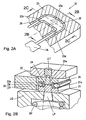
- Fig. 1A and Fig. 1B schematically show a first embodiment of a cuvette according to the invention in cross-section and in longitudinal section in the direction of the arrow IB.
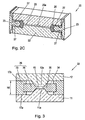
- Fig. 2A, Fig. 2B and Fig. 2C show a second embodiment of a cuvette according to the invention in an isometric view, in a sectional view taken along the line 2B and in a sectional view along the line 2C of Fig. 2A
- Fig. 3 schematically shows a third embodiment of a cuvette according to the invention in cross section.
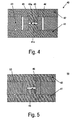
- Fig. 4 schematically shows a fourth embodiment of a cuvette according to the invention in cross section.
- Fig. 5 schematically shows a fifth embodiment of a cuvette according to the invention in cross section.
- Fig. 6 schematically shows a modular spectroscopic analyzer in which a cuvette according to the invention is used.
- a first embodiment of a cuvette according to the invention. 10 for a spectroscopic analyzer comprises a spacer 13, which forms a recess 14.
- the spacer 13 has a height h6 and has plane-parallel upper and lower sides.
- the cuvette 10 comprises a first and a second transparent element 11, 12, which have a substantially flat, plate-shaped basic configuration with height h1 or h2.
- Each of the transparent elements 11, 12 has a shoulder 11a, 12a which extends from the plate-shaped base by a height h3, h4.
- the paragraphs 11a, 12a have a trapezoidal cross-section in the present embodiment, but the invention is not limited to such a cross-sectional shape.
- the lower first transparent element 11 in the drawing lies with its base flat against the underside of the spacer 13, wherein the shoulder 11a of the first transparent element extends into the recess 14 of the spacer 13.
- the top in the drawing second transparent element 12 is located with his.
- the two transparent elements 11, 12 are glued to the spacer 13 by means of dimensionally stable adhesive layers 17a, 17b, wherein the adhesive is preferably a UV-curing adhesive, which is cured by irradiation with light through the transparent elements 11,12.
- the cuvette 10 comprises a sealing element 16, which is arranged in the recess 14 of the spacer 13 between the paragraphs 11a, 12a and abuts against the side walls 11b, 12b of the paragraphs 11a, 12a. Together with the sealing element 16, the facing surfaces of the shoulders 11a, 12a define a straight sample passage 15 in this embodiment.
- the sample passage 15 opens at its opposite ends into an inlet opening 10a and an outlet opening 10b.
- the height of the sample channel 15 corresponds to the distance h5 of the mutually facing end faces of the paragraphs 11a, 12a and thus is substantially less than the height h6 of the spacer 13 and the heights h1, h2 of the plate-shaped bases of the transparent elements 11, 12 and as the total height (h1 + h3 or h2 + h4) of the transparent elements 11, 12. It can be seen that can be used by the inventive principle for both the spacer 13 and the transparent elements 11, 12 relatively thick-walled elements, due to their configuration and arrangement, however, give a sample channel 15 with a very small height h5. It should be mentioned that in a variant of this first embodiment of the cuvette 10 according to the invention one of the two transparent elements 11, 12 could also be designed as a flat plate.
- the spacer 13 is made of an injection-moldable plastic having high modulus values of preferably more than 2500 MPa, more preferably more than 5000 MPa.
- the transparent elements 11, 12 are made of glass, preferably pressed glass, which can be processed well. Alternatively, they are made of a plastic having the following properties: low stress birefringence, low creep, no / low gas permeability, chemical resistance, heat resistance, optical transparency in the visible (VIS) and near infrared (NIR) wavelengths. Preferably, the transparent elements made of plastics from the group of thermoplastic olefin polymers.
- the sealing element 16 consists of an elastomer, preferably with a Shore D hardness between 50 and 80, more preferably with a Shore D hardness between 60 and 70. It lies flat against side walls 11b, 12b of the heels 11a, 12a of the transparent elements 11, 12th at. In order to prevent a portion of the sample from penetrating into the interface between the side walls 11b, 12b and the sealing element 16 due to the capillary effect, the sealing element 16 is biased against the shoulders 11, 12, whereby a portion 16a of the sealing element 16 in the space between the mutually facing end surfaces of the paragraphs 11a, 12a urges and closes it laterally.
- the cuvette 10 is produced by first gluing the first transparent element 11 to the spacer 13 in such a way that its shoulder 11a extends into the recess 14. Subsequently, the sealing member 16, as in the Figures 1A and 1B shown attached to the paragraph 11 a. Thereafter, the second transparent member 12 is positioned on the spacer 13 so that its shoulder 12a is directed into the recess 14 and presses against the sealing member 16. This results in the sample channel 15. By means of a micrometer screw, the height of the second transparent element 12 is adjusted so that the sample channel has the predefined height h5. The adjustment of the distance of the second transparent element 12 is preferably carried out by online measurement of the actual distance of the end faces (inner boundary surfaces of the sample channel) of the paragraphs 11 a, 12 a by means of a confocal microscope.
- a UV-curing adhesive is introduced into the boundary layer between the spacer 13 and the second transparent member 12 and cured by irradiation with UV light, whereby an adhesive layer 17b having a precisely defined thickness is obtained.
- the cuvette 20 has a spacer 23, a first and a second transparent element 21, 22 and a sealing element 26.
- the two transparent elements 21, 22 each have a shoulder 21a, 22a and are arranged opposite each other on the spacer 23 such that the two shoulders 21a, 22a face each other and extend into a channel-shaped recess 24.
- the end faces of the shoulders 21a, 22a have a distance from one another which corresponds to a defined height of a sample channel 25 formed between the end faces of the shoulders 21a, 22a.
- the sample channel 25 is sealed around its periphery by a sealing member 26, the sealing member 26 abuts the lateral surfaces of the shoulders 21 a, 22 a and urges in the gap therebetween.
- the sealing element 26 is formed with the spacer 23 as a combination element 29, for example a 2-component injection molded part or a composite pressed part.
- the materials of the spacer 23 and the sealing member 26 are as indicated above.
- the sample channel 25 has an optical measuring area 25a, in which the transparent elements 21, 22 are arranged plane-parallel. To avoid edge effects, the optical measuring area 25a is spaced from the edge of the sample channel 25.
- a light guide LL1 which emits light through the measuring area 25a along the light path LP, which is analyzed spectroscopically after passing through the measuring area 25, opens near the measuring area 25a.
- reflective optical measuring systems are also provided.
- the sample channel 25 is arcuate, so that the inlet port 20a for the sample PB and the outlet port 20b are on the same side, which has the advantage of a reduced construction volume and a facilitated interchangeability of the cuvette. Furthermore, it should be noted that the width of the sample channel 25 tapers from a central region that includes the measurement region 25a to the inlet opening 20a and to the outlet opening 20b, but the sample channel height increases, so that the cross-sectional area of the sample channel 25 over its length in the Remains essentially constant. This prevents turbulence of the sample PB in the sample channel 25. For the same purpose, the sample channel 25 only steady changes in the channel shape
- the two transparent elements 21, 22 can be glued to the spacer 23, as described above.
- the spacer 23 As an alternative, in this embodiment, also pressing or plugging offers.
- the cuvette 20 is designed specifically for spectroscopic analysis of a blood sample as a sample PB performing hemolysis of the blood sample in the cuvette 20 prior to spectroscopic analysis.
- the cuvette 20 is mechanically clamped in an ultrasonic generator UG (symbolized by the biasing spring SP).
- the ultrasound generator UG generates ultrasound energy and transmits it to the transparent elements 21, 22, whereby hemolysis of the sample PB takes place in the sample channel 25.
- Fig. 2C showing a longitudinal section through the sample channel 25, it can best be seen that the sample channel 25 has inlet slopes tapered in the shape of a wedge to the measurement area 25a and has a plane-parallel course of the surfaces of the transparent elements 21, 22 defining the sample channel in the measurement area 25. Furthermore are in Fig. 2C also to see the adhesive layers 27, with which the spacer 23 with the two transparent elements 21, 22 is glued.
- the adhesive is a form-stable adhesive after curing, so that the adhesive layers 27 have a defined thickness.
- the first and the second transparent element 11, 12 have a substantially flat, plate-shaped base configuration and in each case a trapezoidal shoulder 11a, 12a, which extends from the plate-shaped base.
- the transparent elements 11, 12 are held by a spacer 33 at a distance from each other, wherein the spacer 33 has a height h6, has plane-parallel upper and lower sides and a recess 34 defined.
- the spacer 33 is made, for example, from an injection-moldable plastic with high modulus values of preferably more than 2500 MPa.
- the two transparent elements 11, 12 are glued to the spacer 33 by means of dimensionally stable adhesive layers 17a, 17b.
- the cuvette 30 comprises a sealing element 36, which is arranged in the recess 34 of the spacer 33 between the shoulders 11a, 12a and abuts against the side walls of the shoulders 11a, 12a. Together with the sealing element 36, the facing surfaces of the shoulders 11a, 12a define the sample channel 15.
- the sealing element 16 is made of an elastomer, preferably with a Shore D hardness between 50 and 80, more preferably with a Shore D hardness between 60 and 70.
- the sealing element 36 is formed together with the spacer 33 as a combination element 39.
- the connection of spacer 33 and sealing element 36 to the combination element 39 can be done for example by gluing, plugging or co-extruding.
- Fig. 4 shows a schematic cross section of another embodiment of a cuvette 40 according to the invention.
- This differs from the embodiments of the FIGS. 1 and 3 in that it comprises a first and a second transparent element 41, 42 having a substantially flat, plate-shaped base configuration, but each having a cross-sectionally rectangular shoulder 41 a, 42 a, which extend from the plate-shaped base.
- the transparent elements 41, 42 are held by a spacer 43 at a distance from each other as in the other embodiments.
- the cuvette 40 comprises a sealing element 46 which is arranged in a recess 44 defined by the spacer 43 around the shoulders 41a, 42a and bears against the side walls of the shoulders 41a, 42a. Together with the sealing element 46 the facing surfaces of the shoulders 41a, 42a define a sample channel 45.
- the materials of the transparent elements 41, 42, the spacer 43 and the sealing element 46 are the same as in the other embodiments.
- Fig. 5 shows a schematic cross-section of another embodiment of a cuvette 50 according to the invention, which differs from the embodiment of the Fig. 4 only insofar as it has a spacer 53, which defines a smaller recess compared to the spacer 43, which is completely occupied by the sealing member 46.
- the spacer 53 and the sealing element 46 may also be formed as a combination element.
- the consumables are sent to each other or to the analyzer through coordinated interfaces, e.g. coupled in the form of fluidic docking nipples 105.
- the mechanical connection of the consumables to the respective counterparts can be done by a simple manual movement directly by the user, or by drives located in the device which automatically perform the coupling after the user has put the cassette in "position" only.
- the blood gas analyzer 100 contains an oximetry module in which the concentrations of the hemoglobin derivatives 02Hb, HHb, COHb, MetHb and the blood parameters tHb (total hemoglobin), SO2 (oxygen saturation) and bilirubin are determined by a spectrophotometric measurement method. Characteristic absorption properties of these substances are used and the measured values are evaluated by a mathematical algorithm.
- hemolysis of the whole blood is usually necessary before the optical measurement.
- the blood cells can be destroyed by means of ultrasonic energy in order to carry out a measurement without disturbing light scattering effects.
- Alternative hemolysis principles such as chemical hemolysis can be used for this purpose.
- the oximeter module includes a lamp unit with light source (s), fluid supply and discharge lines, a hemolyzer into which the cuvette 20 is insertable and removable; a light guide which supplies the light generated in the lamp unit to the cuvette 20; and a light guide which collects the light transmitted through the sample in the cuvette 20 and passes it on to a polychromator which spectrally separates the received light and a detector for evaluation the spectral regions of the received light.
- the hemolyzer is configured to insert the cuvette 20 as part of the consumable 102 into the hemolyzer when the consumable 102 is inserted into the analyzer 100 and to be removed from the hemolyzer when the consumable 102 is withdrawn from the analyzer 100.
- This construction avoids the clogging problems on oximeter modules of known analyzers in which an optical measuring chamber (cuvette) is designed as an integral part of the analyzer which remains permanently in the instrument.
Landscapes
- Health & Medical Sciences (AREA)
- Chemical & Material Sciences (AREA)
- Analytical Chemistry (AREA)
- General Health & Medical Sciences (AREA)
- Hematology (AREA)
- Clinical Laboratory Science (AREA)
- Chemical Kinetics & Catalysis (AREA)
- Physics & Mathematics (AREA)
- Life Sciences & Earth Sciences (AREA)
- Biochemistry (AREA)
- General Physics & Mathematics (AREA)
- Immunology (AREA)
- Pathology (AREA)
- Optical Measuring Cells (AREA)
- Automatic Analysis And Handling Materials Therefor (AREA)
- Investigating Or Analysing Materials By Optical Means (AREA)
Applications Claiming Priority (2)
| Application Number | Priority Date | Filing Date | Title |
|---|---|---|---|
| US98744807P | 2007-11-13 | 2007-11-13 | |
| PCT/EP2008/009514 WO2009062667A1 (de) | 2007-11-13 | 2008-11-12 | Küvette und verfahren zur verwendung der küvette |
Publications (2)
| Publication Number | Publication Date |
|---|---|
| EP2217376A1 EP2217376A1 (de) | 2010-08-18 |
| EP2217376B1 true EP2217376B1 (de) | 2013-01-09 |
Family
ID=40365362
Family Applications (1)
| Application Number | Title | Priority Date | Filing Date |
|---|---|---|---|
| EP08850514A Active EP2217376B1 (de) | 2007-11-13 | 2008-11-12 | Küvette und verfahren zur verwendung der küvette |
Country Status (9)
| Country | Link |
|---|---|
| US (1) | US7948619B2 (ja) |
| EP (1) | EP2217376B1 (ja) |
| JP (1) | JP5209057B2 (ja) |
| CN (1) | CN101855019B (ja) |
| CA (1) | CA2701751C (ja) |
| DK (1) | DK2217376T3 (ja) |
| ES (1) | ES2400733T3 (ja) |
| HK (1) | HK1144407A1 (ja) |
| WO (1) | WO2009062667A1 (ja) |
Families Citing this family (11)
| Publication number | Priority date | Publication date | Assignee | Title |
|---|---|---|---|---|
| EP2187209B1 (de) * | 2008-11-12 | 2018-03-28 | Roche Diagnostics GmbH | Hämolysator |
| US8502969B2 (en) * | 2009-12-16 | 2013-08-06 | Boule Medical Ab | Miniature flow-through cuvette and spectrophotometer containing the same |
| US8970837B2 (en) | 2013-03-14 | 2015-03-03 | Laxco Inc. | Apparatus for taking an accurate photometric measurement of a liquid |
| WO2015010709A1 (en) * | 2013-07-22 | 2015-01-29 | Sentec Ag | Sensor for detection of gas and method for detection of gas |
| JP6480210B2 (ja) * | 2014-02-28 | 2019-03-06 | アークレイ株式会社 | プラズマ発生用チップ、プラズマ発生装置およびプラズマ分光分析方法 |
| US9976946B2 (en) * | 2016-04-21 | 2018-05-22 | Instrumentation Laboratory Company | Optical flow cell and test head apparatus |
| US10288556B2 (en) | 2016-04-21 | 2019-05-14 | Instrumentation Laboratory Company | Optical flow cell apparatus and method for reducing deflection of sample chamber |
| JP7147952B2 (ja) * | 2019-02-21 | 2022-10-05 | 株式会社島津製作所 | クロマトグラフ用検出器 |
| CN110487764B (zh) * | 2019-08-30 | 2024-06-21 | 天津陆海石油设备系统工程有限责任公司 | 定量荧光分析仪的手自动进样方式切换装置 |
| EP4188604A4 (en) * | 2020-08-03 | 2024-01-31 | Siemens Healthcare Diagnostics, Inc. | LYSIS DEVICES INCLUDING A PIEZOELECTRIC ELEMENT AND METHODS |
| CN114965323A (zh) * | 2022-06-23 | 2022-08-30 | 秦皇岛水熊科技有限公司 | 一种光谱滴定分析方法中测量数据有效性的判定方法、系统及装置 |
Family Cites Families (13)
| Publication number | Priority date | Publication date | Assignee | Title |
|---|---|---|---|---|
| US3972614A (en) | 1974-07-10 | 1976-08-03 | Radiometer A/S | Method and apparatus for measuring one or more constituents of a blood sample |
| CN85200040U (zh) * | 1985-04-01 | 1985-12-20 | 清华大学 | 池厚连续可调加温高压红外流动池 |
| CA2005622A1 (en) * | 1989-12-15 | 1991-06-15 | Patrick T.T. Wong | Infrared absorption spectra recording, high pressure sample holder |
| CA2156226C (en) * | 1994-08-25 | 1999-02-23 | Takayuki Taguchi | Biological fluid analyzing device and method |
| US5757482A (en) * | 1995-04-20 | 1998-05-26 | Perseptive Biosystems, Inc. | Module for optical detection in microscale fluidic analyses |
| US6579722B1 (en) * | 1995-07-10 | 2003-06-17 | The United States Of America As Represented By The Secretary Of The Navy | Chemiluminescence chemical detection of vapors and device therefor |
| US20050037505A1 (en) | 2000-05-11 | 2005-02-17 | James Samsoondar | Spectroscopic method and apparatus for analyte measurement |
| US6678051B2 (en) * | 2001-01-18 | 2004-01-13 | Systec, Inc. | Flow cells utilizing photometric techniques |
| JP4199609B2 (ja) * | 2002-07-12 | 2008-12-17 | 三菱化学株式会社 | 分析用チップ、分析用チップユニット及び分析装置ならびに分析用チップの作製方法 |
| US6771366B2 (en) * | 2002-10-04 | 2004-08-03 | J.M. Canty Inc. | Fluid flow cell |
| DE10316723A1 (de) * | 2003-04-09 | 2004-11-18 | Siemens Ag | Probenplatte zum Einbau in eine Gehäusestruktur |
| US7307717B2 (en) * | 2005-09-16 | 2007-12-11 | Lockheed Martin Corporation | Optical flow cell capable of use in high temperature and high pressure environment |
| AU2007319975B2 (en) * | 2006-11-09 | 2011-03-03 | Sru Biosystems, Inc. | Photonic crystal sensors with integrated fluid containment structure |
-
2008
- 2008-11-12 JP JP2010532506A patent/JP5209057B2/ja active Active
- 2008-11-12 US US12/269,329 patent/US7948619B2/en active Active
- 2008-11-12 ES ES08850514T patent/ES2400733T3/es active Active
- 2008-11-12 CA CA2701751A patent/CA2701751C/en not_active Expired - Fee Related
- 2008-11-12 EP EP08850514A patent/EP2217376B1/de active Active
- 2008-11-12 CN CN2008801165748A patent/CN101855019B/zh active Active
- 2008-11-12 DK DK08850514.4T patent/DK2217376T3/da active
- 2008-11-12 WO PCT/EP2008/009514 patent/WO2009062667A1/de active Application Filing
-
2010
- 2010-11-25 HK HK10110970.1A patent/HK1144407A1/en not_active IP Right Cessation
Also Published As
| Publication number | Publication date |
|---|---|
| ES2400733T3 (es) | 2013-04-11 |
| JP5209057B2 (ja) | 2013-06-12 |
| DK2217376T3 (da) | 2013-04-15 |
| CA2701751C (en) | 2012-12-11 |
| JP2011503562A (ja) | 2011-01-27 |
| US20090153851A1 (en) | 2009-06-18 |
| CN101855019A (zh) | 2010-10-06 |
| CA2701751A1 (en) | 2009-05-22 |
| CN101855019B (zh) | 2013-02-06 |
| WO2009062667A1 (de) | 2009-05-22 |
| EP2217376A1 (de) | 2010-08-18 |
| US7948619B2 (en) | 2011-05-24 |
| HK1144407A1 (en) | 2011-02-18 |
Similar Documents
| Publication | Publication Date | Title |
|---|---|---|
| EP2217376B1 (de) | Küvette und verfahren zur verwendung der küvette | |
| EP2209554B1 (de) | Modulare sensorkassette | |
| EP2830763B1 (de) | Integriertes einweg-chipkartuschensystem für mobile multiparameteranalysen chemischer und/oder biologischer substanzen | |
| DE60017713T2 (de) | Schützender teststreifenaufbau für optische analysevorrichtung | |
| EP0618443B1 (de) | Teststreifenanalysesystem | |
| EP2257783B1 (de) | Küvette und verfahren zur optischen untersuchung kleiner flüssigkeitsmengen | |
| EP2187209B1 (de) | Hämolysator | |
| EP0460343B1 (de) | Einweg-Messelement zur Analyse von gasförmigen oder flüssigen Proben | |
| EP0722567B1 (de) | Messeinrichtung zur analyse von fluiden | |
| DE2422260B2 (de) | Einrichtung zur Herstellung einer optisch zu untersuchenden Meßflüssigkeit | |
| EP3074133B1 (de) | Filtrationsvorrichtung für flüssige proben | |
| EP3710164B1 (de) | Sensorkassette | |
| DE10140565B4 (de) | Vorrichtung zur Gas- oder Flüssigkeitsabscheidung aus microfluidischen Durchflusssystemen | |
| DE102021111102A1 (de) | Teststreifenanordnung mit Behältern | |
| DE2905234A1 (de) | Probenzelle und ruehrer fuer spektrophotometrie | |
| DD218959A1 (de) | Vorrichtung zur photometrischen messung mechanischer eigenschaften von biologischen partikeln | |
| EP1087224B1 (de) | Elektrochemische Messvorrichtung mit planarem Sensorträger | |
| WO2005050183A2 (de) | Vorrichtung und verfahren zur untersuchung einer flüssigkeitsprobe | |
| EP2693943B1 (de) | Analysesystem mit messvorrichtung und testelement | |
| EP0940181B1 (de) | Pinplatte mit aufsteckbarer oder aufklebbarer Halterung | |
| DE102021203637A1 (de) | Eingabekammer zum Eingeben einer Probenentnahmevorrichtung in eine mikrofluidische Vorrichtung, mikrofluidische Vorrichtung, Verfahren zum Betreiben und Verfahren zum Herstellen einer mikrofluidischen Vorrichtung | |
| DE102005002990A1 (de) | Fluidleitungssystem für einen Bio-Chip | |
| DE7416082U1 (de) | Einrichtung zur Herstellung einer optisch zu untersuchenden Meßflüssigkeit |
Legal Events
| Date | Code | Title | Description |
|---|---|---|---|
| PUAI | Public reference made under article 153(3) epc to a published international application that has entered the european phase |
Free format text: ORIGINAL CODE: 0009012 |
|
| 17P | Request for examination filed |
Effective date: 20100325 |
|
| AK | Designated contracting states |
Kind code of ref document: A1 Designated state(s): AT BE BG CH CY CZ DE DK EE ES FI FR GB GR HR HU IE IS IT LI LT LU LV MC MT NL NO PL PT RO SE SI SK TR |
|
| AX | Request for extension of the european patent |
Extension state: AL BA MK RS |
|
| DAX | Request for extension of the european patent (deleted) | ||
| GRAP | Despatch of communication of intention to grant a patent |
Free format text: ORIGINAL CODE: EPIDOSNIGR1 |
|
| GRAS | Grant fee paid |
Free format text: ORIGINAL CODE: EPIDOSNIGR3 |
|
| GRAA | (expected) grant |
Free format text: ORIGINAL CODE: 0009210 |
|
| AK | Designated contracting states |
Kind code of ref document: B1 Designated state(s): AT BE BG CH CY CZ DE DK EE ES FI FR GB GR HR HU IE IS IT LI LT LU LV MC MT NL NO PL PT RO SE SI SK TR |
|
| REG | Reference to a national code |
Ref country code: GB Ref legal event code: FG4D Free format text: NOT ENGLISH |
|
| REG | Reference to a national code |
Ref country code: CH Ref legal event code: EP Ref country code: AT Ref legal event code: REF Ref document number: 592418 Country of ref document: AT Kind code of ref document: T Effective date: 20130115 |
|
| REG | Reference to a national code |
Ref country code: IE Ref legal event code: FG4D Free format text: LANGUAGE OF EP DOCUMENT: GERMAN |
|
| REG | Reference to a national code |
Ref country code: DE Ref legal event code: R096 Ref document number: 502008009085 Country of ref document: DE Effective date: 20130314 |
|
| REG | Reference to a national code |
Ref country code: ES Ref legal event code: FG2A Ref document number: 2400733 Country of ref document: ES Kind code of ref document: T3 Effective date: 20130411 |
|
| REG | Reference to a national code |
Ref country code: DK Ref legal event code: T3 |
|
| PG25 | Lapsed in a contracting state [announced via postgrant information from national office to epo] |
Ref country code: SI Free format text: LAPSE BECAUSE OF FAILURE TO SUBMIT A TRANSLATION OF THE DESCRIPTION OR TO PAY THE FEE WITHIN THE PRESCRIBED TIME-LIMIT Effective date: 20130109 |
|
| REG | Reference to a national code |
Ref country code: NL Ref legal event code: VDEP Effective date: 20130109 |
|
| REG | Reference to a national code |
Ref country code: LT Ref legal event code: MG4D |
|
| PG25 | Lapsed in a contracting state [announced via postgrant information from national office to epo] |
Ref country code: SE Free format text: LAPSE BECAUSE OF FAILURE TO SUBMIT A TRANSLATION OF THE DESCRIPTION OR TO PAY THE FEE WITHIN THE PRESCRIBED TIME-LIMIT Effective date: 20130109 Ref country code: LT Free format text: LAPSE BECAUSE OF FAILURE TO SUBMIT A TRANSLATION OF THE DESCRIPTION OR TO PAY THE FEE WITHIN THE PRESCRIBED TIME-LIMIT Effective date: 20130109 Ref country code: NO Free format text: LAPSE BECAUSE OF FAILURE TO SUBMIT A TRANSLATION OF THE DESCRIPTION OR TO PAY THE FEE WITHIN THE PRESCRIBED TIME-LIMIT Effective date: 20130409 Ref country code: IS Free format text: LAPSE BECAUSE OF FAILURE TO SUBMIT A TRANSLATION OF THE DESCRIPTION OR TO PAY THE FEE WITHIN THE PRESCRIBED TIME-LIMIT Effective date: 20130509 Ref country code: BG Free format text: LAPSE BECAUSE OF FAILURE TO SUBMIT A TRANSLATION OF THE DESCRIPTION OR TO PAY THE FEE WITHIN THE PRESCRIBED TIME-LIMIT Effective date: 20130409 |
|
| PG25 | Lapsed in a contracting state [announced via postgrant information from national office to epo] |
Ref country code: NL Free format text: LAPSE BECAUSE OF FAILURE TO SUBMIT A TRANSLATION OF THE DESCRIPTION OR TO PAY THE FEE WITHIN THE PRESCRIBED TIME-LIMIT Effective date: 20130109 Ref country code: PT Free format text: LAPSE BECAUSE OF FAILURE TO SUBMIT A TRANSLATION OF THE DESCRIPTION OR TO PAY THE FEE WITHIN THE PRESCRIBED TIME-LIMIT Effective date: 20130509 Ref country code: FI Free format text: LAPSE BECAUSE OF FAILURE TO SUBMIT A TRANSLATION OF THE DESCRIPTION OR TO PAY THE FEE WITHIN THE PRESCRIBED TIME-LIMIT Effective date: 20130109 Ref country code: PL Free format text: LAPSE BECAUSE OF FAILURE TO SUBMIT A TRANSLATION OF THE DESCRIPTION OR TO PAY THE FEE WITHIN THE PRESCRIBED TIME-LIMIT Effective date: 20130109 Ref country code: GR Free format text: LAPSE BECAUSE OF FAILURE TO SUBMIT A TRANSLATION OF THE DESCRIPTION OR TO PAY THE FEE WITHIN THE PRESCRIBED TIME-LIMIT Effective date: 20130410 Ref country code: LV Free format text: LAPSE BECAUSE OF FAILURE TO SUBMIT A TRANSLATION OF THE DESCRIPTION OR TO PAY THE FEE WITHIN THE PRESCRIBED TIME-LIMIT Effective date: 20130109 |
|
| PG25 | Lapsed in a contracting state [announced via postgrant information from national office to epo] |
Ref country code: HR Free format text: LAPSE BECAUSE OF FAILURE TO SUBMIT A TRANSLATION OF THE DESCRIPTION OR TO PAY THE FEE WITHIN THE PRESCRIBED TIME-LIMIT Effective date: 20130109 |
|
| PG25 | Lapsed in a contracting state [announced via postgrant information from national office to epo] |
Ref country code: CZ Free format text: LAPSE BECAUSE OF FAILURE TO SUBMIT A TRANSLATION OF THE DESCRIPTION OR TO PAY THE FEE WITHIN THE PRESCRIBED TIME-LIMIT Effective date: 20130109 Ref country code: EE Free format text: LAPSE BECAUSE OF FAILURE TO SUBMIT A TRANSLATION OF THE DESCRIPTION OR TO PAY THE FEE WITHIN THE PRESCRIBED TIME-LIMIT Effective date: 20130109 Ref country code: RO Free format text: LAPSE BECAUSE OF FAILURE TO SUBMIT A TRANSLATION OF THE DESCRIPTION OR TO PAY THE FEE WITHIN THE PRESCRIBED TIME-LIMIT Effective date: 20130109 Ref country code: SK Free format text: LAPSE BECAUSE OF FAILURE TO SUBMIT A TRANSLATION OF THE DESCRIPTION OR TO PAY THE FEE WITHIN THE PRESCRIBED TIME-LIMIT Effective date: 20130109 |
|
| PLBE | No opposition filed within time limit |
Free format text: ORIGINAL CODE: 0009261 |
|
| STAA | Information on the status of an ep patent application or granted ep patent |
Free format text: STATUS: NO OPPOSITION FILED WITHIN TIME LIMIT |
|
| PG25 | Lapsed in a contracting state [announced via postgrant information from national office to epo] |
Ref country code: CY Free format text: LAPSE BECAUSE OF FAILURE TO SUBMIT A TRANSLATION OF THE DESCRIPTION OR TO PAY THE FEE WITHIN THE PRESCRIBED TIME-LIMIT Effective date: 20130109 |
|
| 26N | No opposition filed |
Effective date: 20131010 |
|
| REG | Reference to a national code |
Ref country code: DE Ref legal event code: R097 Ref document number: 502008009085 Country of ref document: DE Effective date: 20131010 |
|
| PGFP | Annual fee paid to national office [announced via postgrant information from national office to epo] |
Ref country code: AT Payment date: 20131025 Year of fee payment: 6 |
|
| PGFP | Annual fee paid to national office [announced via postgrant information from national office to epo] |
Ref country code: IT Payment date: 20131126 Year of fee payment: 6 Ref country code: ES Payment date: 20131121 Year of fee payment: 6 |
|
| BERE | Be: lapsed |
Owner name: F. HOFFMANN-LA ROCHE A.G. Effective date: 20131130 Owner name: ROCHE DIAGNOSTICS G.M.B.H. Effective date: 20131130 |
|
| PG25 | Lapsed in a contracting state [announced via postgrant information from national office to epo] |
Ref country code: MC Free format text: LAPSE BECAUSE OF FAILURE TO SUBMIT A TRANSLATION OF THE DESCRIPTION OR TO PAY THE FEE WITHIN THE PRESCRIBED TIME-LIMIT Effective date: 20130109 |
|
| REG | Reference to a national code |
Ref country code: IE Ref legal event code: MM4A |
|
| PG25 | Lapsed in a contracting state [announced via postgrant information from national office to epo] |
Ref country code: BE Free format text: LAPSE BECAUSE OF NON-PAYMENT OF DUE FEES Effective date: 20131130 |
|
| PG25 | Lapsed in a contracting state [announced via postgrant information from national office to epo] |
Ref country code: IE Free format text: LAPSE BECAUSE OF NON-PAYMENT OF DUE FEES Effective date: 20131112 |
|
| PGFP | Annual fee paid to national office [announced via postgrant information from national office to epo] |
Ref country code: CH Payment date: 20141027 Year of fee payment: 7 |
|
| PG25 | Lapsed in a contracting state [announced via postgrant information from national office to epo] |
Ref country code: TR Free format text: LAPSE BECAUSE OF FAILURE TO SUBMIT A TRANSLATION OF THE DESCRIPTION OR TO PAY THE FEE WITHIN THE PRESCRIBED TIME-LIMIT Effective date: 20130109 |
|
| REG | Reference to a national code |
Ref country code: AT Ref legal event code: MM01 Ref document number: 592418 Country of ref document: AT Kind code of ref document: T Effective date: 20141112 |
|
| PG25 | Lapsed in a contracting state [announced via postgrant information from national office to epo] |
Ref country code: HU Free format text: LAPSE BECAUSE OF FAILURE TO SUBMIT A TRANSLATION OF THE DESCRIPTION OR TO PAY THE FEE WITHIN THE PRESCRIBED TIME-LIMIT; INVALID AB INITIO Effective date: 20081112 Ref country code: LU Free format text: LAPSE BECAUSE OF NON-PAYMENT OF DUE FEES Effective date: 20131112 |
|
| PG25 | Lapsed in a contracting state [announced via postgrant information from national office to epo] |
Ref country code: AT Free format text: LAPSE BECAUSE OF NON-PAYMENT OF DUE FEES Effective date: 20141112 Ref country code: MT Free format text: LAPSE BECAUSE OF FAILURE TO SUBMIT A TRANSLATION OF THE DESCRIPTION OR TO PAY THE FEE WITHIN THE PRESCRIBED TIME-LIMIT Effective date: 20130109 |
|
| REG | Reference to a national code |
Ref country code: FR Ref legal event code: PLFP Year of fee payment: 8 |
|
| REG | Reference to a national code |
Ref country code: ES Ref legal event code: FD2A Effective date: 20151229 |
|
| PG25 | Lapsed in a contracting state [announced via postgrant information from national office to epo] |
Ref country code: IT Free format text: LAPSE BECAUSE OF NON-PAYMENT OF DUE FEES Effective date: 20141112 |
|
| PG25 | Lapsed in a contracting state [announced via postgrant information from national office to epo] |
Ref country code: ES Free format text: LAPSE BECAUSE OF NON-PAYMENT OF DUE FEES Effective date: 20141113 |
|
| REG | Reference to a national code |
Ref country code: CH Ref legal event code: PL |
|
| PG25 | Lapsed in a contracting state [announced via postgrant information from national office to epo] |
Ref country code: LI Free format text: LAPSE BECAUSE OF NON-PAYMENT OF DUE FEES Effective date: 20151130 Ref country code: CH Free format text: LAPSE BECAUSE OF NON-PAYMENT OF DUE FEES Effective date: 20151130 |
|
| REG | Reference to a national code |
Ref country code: FR Ref legal event code: PLFP Year of fee payment: 9 |
|
| REG | Reference to a national code |
Ref country code: FR Ref legal event code: PLFP Year of fee payment: 10 |
|
| REG | Reference to a national code |
Ref country code: FR Ref legal event code: PLFP Year of fee payment: 11 |
|
| PGFP | Annual fee paid to national office [announced via postgrant information from national office to epo] |
Ref country code: GB Payment date: 20231019 Year of fee payment: 16 |
|
| PGFP | Annual fee paid to national office [announced via postgrant information from national office to epo] |
Ref country code: FR Payment date: 20231020 Year of fee payment: 16 Ref country code: DK Payment date: 20231019 Year of fee payment: 16 Ref country code: DE Payment date: 20231019 Year of fee payment: 16 |