EP2216552B1 - Plaque inférieure polyvalente pour pompes centrifuges, en particulier pour des pompes de circulation de chaudière - Google Patents
Plaque inférieure polyvalente pour pompes centrifuges, en particulier pour des pompes de circulation de chaudière Download PDFInfo
- Publication number
- EP2216552B1 EP2216552B1 EP09425040.4A EP09425040A EP2216552B1 EP 2216552 B1 EP2216552 B1 EP 2216552B1 EP 09425040 A EP09425040 A EP 09425040A EP 2216552 B1 EP2216552 B1 EP 2216552B1
- Authority
- EP
- European Patent Office
- Prior art keywords
- bottom plate
- connector
- cover
- motor cover
- plate according
- Prior art date
- Legal status (The legal status is an assumption and is not a legal conclusion. Google has not performed a legal analysis and makes no representation as to the accuracy of the status listed.)
- Active
Links
Images


Classifications
-
- F—MECHANICAL ENGINEERING; LIGHTING; HEATING; WEAPONS; BLASTING
- F04—POSITIVE - DISPLACEMENT MACHINES FOR LIQUIDS; PUMPS FOR LIQUIDS OR ELASTIC FLUIDS
- F04D—NON-POSITIVE-DISPLACEMENT PUMPS
- F04D25/00—Pumping installations or systems
- F04D25/02—Units comprising pumps and their driving means
- F04D25/08—Units comprising pumps and their driving means the working fluid being air, e.g. for ventilation
- F04D25/082—Units comprising pumps and their driving means the working fluid being air, e.g. for ventilation the unit having provision for cooling the motor
-
- F—MECHANICAL ENGINEERING; LIGHTING; HEATING; WEAPONS; BLASTING
- F04—POSITIVE - DISPLACEMENT MACHINES FOR LIQUIDS; PUMPS FOR LIQUIDS OR ELASTIC FLUIDS
- F04B—POSITIVE-DISPLACEMENT MACHINES FOR LIQUIDS; PUMPS
- F04B53/00—Component parts, details or accessories not provided for in, or of interest apart from, groups F04B1/00 - F04B23/00 or F04B39/00 - F04B47/00
- F04B53/16—Casings; Cylinders; Cylinder liners or heads; Fluid connections
-
- F—MECHANICAL ENGINEERING; LIGHTING; HEATING; WEAPONS; BLASTING
- F04—POSITIVE - DISPLACEMENT MACHINES FOR LIQUIDS; PUMPS FOR LIQUIDS OR ELASTIC FLUIDS
- F04B—POSITIVE-DISPLACEMENT MACHINES FOR LIQUIDS; PUMPS
- F04B35/00—Piston pumps specially adapted for elastic fluids and characterised by the driving means to their working members, or by combination with, or adaptation to, specific driving engines or motors, not otherwise provided for
- F04B35/04—Piston pumps specially adapted for elastic fluids and characterised by the driving means to their working members, or by combination with, or adaptation to, specific driving engines or motors, not otherwise provided for the means being electric
-
- F—MECHANICAL ENGINEERING; LIGHTING; HEATING; WEAPONS; BLASTING
- F04—POSITIVE - DISPLACEMENT MACHINES FOR LIQUIDS; PUMPS FOR LIQUIDS OR ELASTIC FLUIDS
- F04D—NON-POSITIVE-DISPLACEMENT PUMPS
- F04D29/00—Details, component parts, or accessories
- F04D29/58—Cooling; Heating; Diminishing heat transfer
- F04D29/5806—Cooling the drive system
-
- F—MECHANICAL ENGINEERING; LIGHTING; HEATING; WEAPONS; BLASTING
- F24—HEATING; RANGES; VENTILATING
- F24D—DOMESTIC- OR SPACE-HEATING SYSTEMS, e.g. CENTRAL HEATING SYSTEMS; DOMESTIC HOT-WATER SUPPLY SYSTEMS; ELEMENTS OR COMPONENTS THEREFOR
- F24D3/00—Hot-water central heating systems
- F24D3/02—Hot-water central heating systems with forced circulation, e.g. by pumps
-
- H—ELECTRICITY
- H02—GENERATION; CONVERSION OR DISTRIBUTION OF ELECTRIC POWER
- H02K—DYNAMO-ELECTRIC MACHINES
- H02K17/00—Asynchronous induction motors; Asynchronous induction generators
- H02K17/02—Asynchronous induction motors
- H02K17/30—Structural association of asynchronous induction motors with auxiliary electric devices influencing the characteristics of the motor or controlling the motor, e.g. with impedances or switches
-
- H—ELECTRICITY
- H02—GENERATION; CONVERSION OR DISTRIBUTION OF ELECTRIC POWER
- H02K—DYNAMO-ELECTRIC MACHINES
- H02K5/00—Casings; Enclosures; Supports
- H02K5/04—Casings or enclosures characterised by the shape, form or construction thereof
- H02K5/10—Casings or enclosures characterised by the shape, form or construction thereof with arrangements for protection from ingress, e.g. water or fingers
-
- H—ELECTRICITY
- H02—GENERATION; CONVERSION OR DISTRIBUTION OF ELECTRIC POWER
- H02K—DYNAMO-ELECTRIC MACHINES
- H02K5/00—Casings; Enclosures; Supports
- H02K5/04—Casings or enclosures characterised by the shape, form or construction thereof
- H02K5/20—Casings or enclosures characterised by the shape, form or construction thereof with channels or ducts for flow of cooling medium
- H02K5/207—Casings or enclosures characterised by the shape, form or construction thereof with channels or ducts for flow of cooling medium with openings in the casing specially adapted for ambient air
-
- H—ELECTRICITY
- H02—GENERATION; CONVERSION OR DISTRIBUTION OF ELECTRIC POWER
- H02K—DYNAMO-ELECTRIC MACHINES
- H02K5/00—Casings; Enclosures; Supports
- H02K5/04—Casings or enclosures characterised by the shape, form or construction thereof
- H02K5/22—Auxiliary parts of casings not covered by groups H02K5/06-H02K5/20, e.g. shaped to form connection boxes or terminal boxes
- H02K5/225—Terminal boxes or connection arrangements
-
- H—ELECTRICITY
- H02—GENERATION; CONVERSION OR DISTRIBUTION OF ELECTRIC POWER
- H02K—DYNAMO-ELECTRIC MACHINES
- H02K9/00—Arrangements for cooling or ventilating
- H02K9/02—Arrangements for cooling or ventilating by ambient air flowing through the machine
-
- H—ELECTRICITY
- H02—GENERATION; CONVERSION OR DISTRIBUTION OF ELECTRIC POWER
- H02K—DYNAMO-ELECTRIC MACHINES
- H02K2205/00—Specific aspects not provided for in the other groups of this subclass relating to casings, enclosures, supports
- H02K2205/09—Machines characterised by drain passages or by venting, breathing or pressure compensating means
Definitions
- the present invention regards a multi-functional closure bottom plate for a centrifugal electric pump, in particular a fluid circulation centrifugal pump of the type used in boiler heating systems.
- Electric pumps of this type usually have a box-shaped or tubular body for holding electromechanical elements associated to a head, which defines the volute of the pump.
- the bottom plate is the structural element that closes the end of the box-shaped body arranged oppositely with respect to the head.
- the bottom plate that closes the box-shaped body is generally sealingly fixed to the rest of the casing, so as to avoid damaging penetrations of fluid into the delicate electromechanical components.
- the thermal gradient due to the difference between the operating temperature of the electric pump and the atmospheric temperature may in unfortunate cases determine the formation, due to condensation, of water on the internal walls of the casing.
- US 2003/0102740 A1 proposes a bottom plate provided with an inner cavity, in which a path defined by concentric collars allows evacuating, by convection, the hot air contained in the casing, though protecting the motor and the board from splashes of fluid coming from the outside.
- the inflowing air and the outflowing air share the same path, that being the reason why the internal circulation is not homogenous on the entire volume of the bottom plate, but mainly involves the areas in proximity to the recirculation holes.
- the technical problem on which the present invention is based is that of providing a bottom plate with low costs of production capable of providing a more efficient system for preventing the water condensation inside the body of an electric pump.
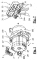
- bottom plate a multi-functional closure bottom plate (hereinafter in the description simply referred to as bottom plate), intended, as observable in figure 1 , to be associated to an electric pump 100, in particular to a centrifugal circulation electric pump 100 of the type used in the boiler heating systems circulators.
- the electric pump 100 is preferably a permanent magnet synchronous pump, but such indication shall not be regarded in the limiting sense.
- the electric pump 100 comprises a box-shaped containment body 101, inside which there are both the stator coils that surround the motor, and the possible electronic components (for example a local control circuit board may be provided for) for controlling the device.
- the possible electronic components for example a local control circuit board may be provided for
- the box-shaped containment body 101 is associated at one of the ends thereof to a head 102, that defines the volute of the centrifugal pump, while the opposite end is closed by the bottom plate 1.
- the box-shaped containment body 101 is extended along a longitudinal axis x-x identified in figure 1 ; under normal operating conditions of the electric pump 100, the axis x-x is horizontal in such a manner that the bottom plate is arranged in a vertical plane.
- the bottom plate 1 comprises two components: an actual motor cover 2, cup-shaped and arranged to be associated - closing it - to the end of the box-shaped containment body 101 oppositely arranged with respect to the head 102; and a connector-holder cover 3, which has the function of bearing one or more electrical connectors 300 and comprises fixing means 30 for such purpose.
- the electrical connectors 300 are preferably two, just like in the embodiments illustrated in the attached figures.
- the electrical connectors are arranged at the end of the electrical cables 301 and they are conceived to be connected to the electric pump 100, to respectively allow electrical power supply and control thereof.
- connection of the electrical connectors 300 to the electric pump 100 may imply, depending on the manufacture of the operated device, both the direct connection with the stator coils of the electric motor, and, preferably, the coupling onto a local circuit board intended to control the motor.
- the motor cover 2 has a coupling opening 21; the connector-holder cover 3 can thus be associated, in a mounted configuration (illustrated in figures 2-5 , 8-9 ), to such coupling opening 21.
- the abovementioned fixing means 30 hold the electrical connectors 300 in a preset connection position with respect to the electric pump 100.
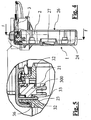
- the mounted bottom plate 1 has an internal aeration path 4, which as previously mentioned allows - by natural convection - the circulation of the air heated during the operation of the electric pump 100, preventing the formation of condensate inside the bottom plate 1 itself.
- Such internal aeration path 4 is extended at least between an inlet opening 22, arranged on the motor cover 2 and an outlet opening 36.
- the internal aeration path starting from the inlet opening, successively crosses the internal volume of the motor cover 2, the aforementioned coupling opening 21, and a labyrinth (path) 32 defined by the connector-holder cover 3, then exiting through the outlet opening 36.
- the inlet opening 22 is in the lower part of the internal aeration path 4 and thus at a lower height with respect to the outlet opening 36, as mentioned, to facilitate the natural convection through the described path.
- the abovementioned labyrinth 32 develops in such a manner as to allow the venting of the convection air, but simultaneously prevent the entry of liquid from the external due to sprays or the like.
- the path and its modes of definition shall be outlined in detail in the description provided hereinafter.
- the presence of the aeration path 4 thus allows the circulation of air through the entire volume of the bottom plate 1, exploiting the natural connective movements of the fluid heated during the operation of the electric pump. Such heating is due to the presence of electronic components active inside the bottom plate 1, or otherwise due to the closeness of the bottom plate 1 to the running electric motor.
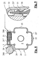
- the connective motion of the heated air, that prevents the formation of condensate inside the electromechanical apparatus, is schematically represented by means of continuous arrows in the attached figures 5 and 6 .
- the motor cover 2 comprises a flat bottom wall 24, departing from whose perimeter are four lateral walls 25, 25', 25" that define the mouth 26 conceived to be associated to the box-shaped containment body 101 described above.
- the aforementioned inlet opening 22 and the coupling opening 21 are preferably arranged on two opposite lateral walls, in such a manner that the air flow that crosses the aeration path 4 involves the entire volume of the bottom plate 1.
- the adjacent lateral walls 25, 25', 25" are connected to each other by double-S-shaped wavy sections, obtained in proximity to which are four holes for inserting screws for connecting to the box-shaped containment body 101.
- a ultrasonic welding of the bottom plate 1 can be performed on the box-shaped containment body 101.
- an inspection hole 27, closable with a special cap, may be provided.
- a hole allows access into the structure, for maintenance purposes, in cases where the motor cover 2 is permanently associated to the electric pump 100.
- the bottom wall 24 lies on a vertical plane; the lateral wall 25' which has the aeration openings 22 is preferably directed downwards and hence the oppositely arranged wall 25" which has the coupling opening is directed upwards.
- the convective stream which transports the hot air upwards allows evacuating the latter through the labyrinth 32.
- the inlet openings 22 are preferably defined, as observable in figures 1 , 6 and 8 , by a plurality of parallel slots obtained on the lower wall 25' of the motor cover 2.
- the motor cover 2 further comprises a projecting panel 23, directed inwards the bottom plate 1, perimetrally with respect to the coupling opening 22.
- Said panel 23 which has a parallelepiped structure, accommodates the electrical connectors 300 therein borne by the connector-holder cover 3. Furthermore, the projecting panel 23 is inserted inside the structure of the connector-holder cover 3, when the latter is mounted.
- cover structure 3 and the panel 23 are not in direct contact, and the cavity present between the two elements defines the part of the labyrinth 32 arranged at the end of the aeration path 4, as observable in the attached figures 5 and 6 .
- the labyrinth 32 is thus composed of a first part defined by the clearances and by the cavities present between the mounted electrical connectors 300 and the projecting panel 23 and a second part developing between the cover structure 3 and the projecting panel 23, then in communication with the external environment through the perimeter opening between the motor cover 2 and the connector-holder cover 3, i.e. by means of the previously described outlet opening 36.
- the connector-holder cover 3 has a main half-shell-shaped portion with a longitudinal extension that faithfully matches that of the upper wall 25" on which it is mounted.
- the main half-shell-shaped portion is the one that bears the electrical connectors 300 therein and the one that, in mounted configuration, holds the projecting panel 23.
- the main portion of the connector-holder cover 3 has two reliefs 31 arranged on its internal surface at one of its longitudinal ends. As observable in figures 8 and 9 , one of these reliefs 31 is engaged with an elastic tooth 28 projecting with respect to the upper wall 25" of the motor cover 2; instead, the other one is engaged with a counter-shaped end portion 23' of the previously described projecting panel 23.
- the fixing means 30 provided for by the connector-holder cover 3 comprise elastic coupling teeth 33, arranged on an inner surface of the cover itself, which collaborate to provide an accommodation for the electrical connectors 300 having a rigid seat 32 obtained projecting on the same surface.
- Such structural elements, well visible in the perspective view of figure 7 allow the snap-insertion of said electrical connectors 300.
- the connector-holder cover has a protection and retention rigid casing 35, which departs from the main portion to the half-shell.
- the internal volumes of such rigid casing 35 and of the main half-shell-shaped portion are separated by a septum, obtained in which are semicircular grooves fittingly arranged for the passage of the electrical cables 301.
- the rigid casing 35 defines a channel for accommodating the electrical cables 301, that are maintained in position by means of two retention arms 35', opposite and offset according to the direction of longitudinal development of the casing 35.
- the motor cover 2 further comprises a cylindrical external seat 29 intended to accommodate a phasing capacitor 200 connectable, by means of the aforementioned electrical cables 301, to one of the electrical connectors 300 held by the connector-holder cover 3.
- the main advantage of the aforedescribed bottom plate lies in the efficient action of preventing the formation of condensate, involving the entire internal volume of the bottom plate itself.
- Another advantage is determined by the external positioning of the phasing capacitor, which considerably reduces the risk of overheating the electric pump device.
- Another advantage lies in the protection of all the electrical and electronic elements from splashes or accidental contact with water or other liquids or vapours, obtained due to the labyrinth and the various casings and covers, advantageously made of waterproof material.
Landscapes
- Engineering & Computer Science (AREA)
- Power Engineering (AREA)
- Mechanical Engineering (AREA)
- General Engineering & Computer Science (AREA)
- Physics & Mathematics (AREA)
- Thermal Sciences (AREA)
- Chemical & Material Sciences (AREA)
- Combustion & Propulsion (AREA)
- Structures Of Non-Positive Displacement Pumps (AREA)
- Connector Housings Or Holding Contact Members (AREA)
Claims (10)
- Plaque de fermeture de fond (1) pour pompe électrique centrifuge (100), du type comprenant un corps de confinement (101) en forme de boîte associé à une tête (102), comprenant: un couvercle de moteur en forme de coupe (2) et agencé pour être associé, en le fermant, à l'extrémité du corps de confinement (102) en forme de boîte disposé à l'opposé de la tête (102), ledit couvercle de moteur (2) ayant une ouverture de couplage (21) ; un couvercle de porte-connecteur (3), pouvant être associé à une configuration montée à ladite ouverture de couplage (21), comprenant des moyens de fixation (30) conçus pour maintenir, dans ladite configuration montée, au moins un connecteur électrique (300) dans une position prédéfinie pour un raccordement à la pompe électrique (100), ladite plaque de fond (1) ayant un circuit d'aération interne (4), prévu pour permettre la circulation par convection naturelle d'air qui est réchauffé pendant le fonctionnement de la pompe électrique (100), empêchant ainsi la formation de condensation à l'intérieur de la plaque de fond (1), caractérisée en ce que le circuit d'aération interne (4) s'étend entre au moins une ouverture d'entrée (22) disposée sur le couvercle de moteur (2) et une ouverture de sortie (36) et traverse successivement le volume interne du couvercle de moteur (2), ladite ouverture de couplage (21) et un labyrinthe (32) défini par le couvercle de porte-connecteur (3).
- Plaque de fond selon la revendication 1, dans laquelle ladite ouverture de sortie (36) est déterminée par la cavité périphérique déterminée entre le couvercle de moteur (2) et le couvercle de porte-connecteur (3) monté sur celui-ci.
- Plaque de fond selon la revendication 2, dans laquelle le couvercle de moteur (2) comprend un panneau en saillie (23) périphérique à ladite ouverture de couplage (22), ledit panneau en saillie (23) étant inséré à l'intérieur du couvercle (3) du porte-connecteur, la cavité présente entre ledit couvercle (3) du porte-connecteur et ledit panneau en saillie (23) définissant au moins une partie du labyrinthe (21).
- Plaque de fond selon la revendication 3, dans laquelle le couvercle de porte connecteur (3) comprend deux reliefs (31) sur sa surface interne conçue pour collaborer avec une dent élastique (28) du couvercle de moteur (2) et une partie de contreforme (23) du panneau en saillie (23') permettant le couplage par encliquetage du couvercle de porte-connecteur (3) sur le couvercle de moteur (2).
- Plaque de fond selon l'une des revendications précédentes, dans laquelle les moyens de fixation (30) comprennent des dents de couplage élastiques (33) disposées sur une surface interne du couvercle de porte-connecteur (3).
- Plaque de fond selon l'un des revendications précédentes, dans laquelle le couvercle de porte-connecteur (3) comprend un coffrage rigide (35) pour protéger et maintenir les câbles électriques (301) associés aux connecteurs électriques (300).
- Plaque de fond (1) selon l'une des revendications précédentes, dans laquelle l'ouverture d'entrée (22) du circuit d'aération (4) est prévue à une hauteur plus basse par rapport à l'ouverture de sortie (36) dans des conditions normales de fonctionnement de la pompe électrique (100).
- Plaque de fond selon la revendication 7, dans laquelle ledit couvercle de moteur (2) comprend une paroi de fond (24), prévue sur un plan vertical (100), et des parois latérales (25, 25', 25") qui relient ladite paroi de fond (24) au corps de confinement en forme de boîte (101) ; lesdites ouvertures d'entrée (22) et ladite ouverture de couplage (21) étant prévues sur deux parois latérales opposés (25, 25', 25"), respectivement sur une paroi inférieure (25') et supérieure (25").
- Plaque de fond selon la revendication 8, dans laquelle les ouvertures d'entrée (22) sont une pluralité de fentes parallèles obtenues sur la paroi inférieure (25') du couvercle de moteur (2).
- Plaque de fond selon l'une des revendications précédentes, dans laquelle le couvercle de moteur comprend un siège externe (29) destiné à recevoir un condensateur de mise en phase (200) connecté à l'un des connecteurs électriques (300) portés par le couvercle de porte-connecteur (3).
Priority Applications (5)
| Application Number | Priority Date | Filing Date | Title |
|---|---|---|---|
| EP09425040.4A EP2216552B8 (fr) | 2009-02-06 | 2009-02-06 | Plaque inférieure polyvalente pour pompes centrifuges, en particulier pour des pompes de circulation de chaudière |
| US12/697,648 US8348640B2 (en) | 2009-02-06 | 2010-02-01 | Multi-functional bottom plate for centrifugal pumps, in particular for boiler circulation pumps |
| RU2010103066/06A RU2516072C2 (ru) | 2009-02-06 | 2010-02-01 | Многофункциональная опорная плита для центробежных насосов, в особенности для насосов для котлов с циркуляцией |
| CN201010112901.1A CN101832269B (zh) | 2009-02-06 | 2010-02-04 | 用于离心泵、特别是锅炉循环泵的多功能封闭底板 |
| KR1020100010995A KR101797626B1 (ko) | 2009-02-06 | 2010-02-05 | 원심 펌프용 특히 보일러 순환 펌프용 다기능 바닥 플레이트 |
Applications Claiming Priority (1)
| Application Number | Priority Date | Filing Date | Title |
|---|---|---|---|
| EP09425040.4A EP2216552B8 (fr) | 2009-02-06 | 2009-02-06 | Plaque inférieure polyvalente pour pompes centrifuges, en particulier pour des pompes de circulation de chaudière |
Publications (3)
| Publication Number | Publication Date |
|---|---|
| EP2216552A1 EP2216552A1 (fr) | 2010-08-11 |
| EP2216552B1 true EP2216552B1 (fr) | 2016-02-03 |
| EP2216552B8 EP2216552B8 (fr) | 2016-03-09 |
Family
ID=40873378
Family Applications (1)
| Application Number | Title | Priority Date | Filing Date |
|---|---|---|---|
| EP09425040.4A Active EP2216552B8 (fr) | 2009-02-06 | 2009-02-06 | Plaque inférieure polyvalente pour pompes centrifuges, en particulier pour des pompes de circulation de chaudière |
Country Status (5)
| Country | Link |
|---|---|
| US (1) | US8348640B2 (fr) |
| EP (1) | EP2216552B8 (fr) |
| KR (1) | KR101797626B1 (fr) |
| CN (1) | CN101832269B (fr) |
| RU (1) | RU2516072C2 (fr) |
Families Citing this family (11)
| Publication number | Priority date | Publication date | Assignee | Title |
|---|---|---|---|---|
| EP2626980B1 (fr) * | 2012-02-08 | 2014-11-05 | Grundfos Holding A/S | Groupe motopompe |
| US8876078B1 (en) * | 2013-02-20 | 2014-11-04 | Daniel N. Gates | HVAC inspection frame device |
| US9709068B2 (en) | 2014-02-19 | 2017-07-18 | Honeywell International Inc. | Sealing arrangement for fuel cell compressor |
| US9537363B2 (en) * | 2014-04-30 | 2017-01-03 | Honeywell International Inc. | Electric motor-driven compressor having an electrical terminal block assembly |
| EP3284160A1 (fr) * | 2015-04-15 | 2018-02-21 | Schaeffler Technologies AG & Co. KG | Actionneur pour un embrayage de véhicule automobile, comprenant un support dans lequel est maintenue une fiche et module hybride muni d'un tel actionneur |
| DE102015114192A1 (de) | 2015-08-26 | 2017-03-02 | Ebm-Papst Mulfingen Gmbh & Co. Kg | Verbindungssystem zur Steckerpositionierung |
| US10715010B2 (en) * | 2017-02-07 | 2020-07-14 | Nidec Motor Corporation | Motor controller can with synthetic housing and metal heat sink |
| KR102514964B1 (ko) * | 2018-06-29 | 2023-03-28 | 엘지전자 주식회사 | 배수펌프 |
| CN113937943B (zh) * | 2021-10-15 | 2023-02-03 | 合肥新沪屏蔽泵有限公司 | 一种电机座及泵组件 |
| KR102697089B1 (ko) * | 2023-11-22 | 2024-08-22 | 지엠비코리아 주식회사 | 전동식 워터펌프 |
| EP4624753A1 (fr) * | 2024-03-28 | 2025-10-01 | Wilo Se | Pompe de circulation comprenant un carter de pompe, un carter de moteur et une boîte à bornes |
Family Cites Families (12)
| Publication number | Priority date | Publication date | Assignee | Title |
|---|---|---|---|---|
| JPS58119744A (ja) * | 1982-01-08 | 1983-07-16 | Fanuc Ltd | モ−タ内蔵主軸台 |
| CN1034191C (zh) * | 1992-03-25 | 1997-03-05 | 付英杰 | 多用异步电机离心泵 |
| JPH09264297A (ja) * | 1996-03-29 | 1997-10-07 | Ebara Corp | 流体機械用ケーシング |
| DE29817873U1 (de) * | 1998-10-07 | 1998-12-17 | Frankl & Kirchner GmbH & Co. KG Fabrik für Elektromotoren und elektrische Apparate, 68723 Schwetzingen | Elektro-Motor |
| ITPD20010272A1 (it) | 2001-11-22 | 2003-05-22 | Askoll Holding Srl | Struttura di accoppiamento motore elettrico / scatola di connessione |
| ITPD20010277A1 (it) * | 2001-11-27 | 2003-05-27 | Askoll Holding Srl | Dispositivo anticondensa particolarmente per motori elettrici. |
| US6661140B2 (en) * | 2001-12-11 | 2003-12-09 | Black & Decker Inc. | Brushless motor having housing enabling alignment of stator and sensor |
| EP1437819B1 (fr) * | 2003-01-10 | 2008-11-05 | Askoll Holding S.r.l. | Moteur à aimants permanents pour pompe de circulation de systèmes de chauffage et de climatisation |
| JP4102245B2 (ja) * | 2003-04-25 | 2008-06-18 | アスモ株式会社 | モータ |
| ATE423910T1 (de) * | 2004-06-30 | 2009-03-15 | Askoll Holding Srl | Axiales lager für elektrische angetriebene pumpe |
| JP2007037280A (ja) * | 2005-07-27 | 2007-02-08 | Mitsubishi Electric Corp | インバータ一体型回転電機 |
| US8049385B2 (en) * | 2008-11-06 | 2011-11-01 | Nidec Motor Corporation | Liquid deflecting baffle for an electric motor |
-
2009
- 2009-02-06 EP EP09425040.4A patent/EP2216552B8/fr active Active
-
2010
- 2010-02-01 RU RU2010103066/06A patent/RU2516072C2/ru active
- 2010-02-01 US US12/697,648 patent/US8348640B2/en active Active
- 2010-02-04 CN CN201010112901.1A patent/CN101832269B/zh active Active
- 2010-02-05 KR KR1020100010995A patent/KR101797626B1/ko active Active
Also Published As
| Publication number | Publication date |
|---|---|
| US8348640B2 (en) | 2013-01-08 |
| KR101797626B1 (ko) | 2017-11-15 |
| EP2216552A1 (fr) | 2010-08-11 |
| US20100202905A1 (en) | 2010-08-12 |
| RU2516072C2 (ru) | 2014-05-20 |
| EP2216552B8 (fr) | 2016-03-09 |
| CN101832269A (zh) | 2010-09-15 |
| RU2010103066A (ru) | 2011-08-10 |
| CN101832269B (zh) | 2014-12-31 |
| KR20100090665A (ko) | 2010-08-16 |
Similar Documents
| Publication | Publication Date | Title |
|---|---|---|
| EP2216552B1 (fr) | Plaque inférieure polyvalente pour pompes centrifuges, en particulier pour des pompes de circulation de chaudière | |
| US20130343935A1 (en) | Heat circulation pump | |
| EP1884010B1 (fr) | Moteur a courant continu sans contacts glissants et ensemble pompe comportant une carte a circuit imprime encapsulee | |
| US20070284954A1 (en) | Totally enclosed fan cooled motor | |
| RU2486370C2 (ru) | Воздуходувка для отопителя транспортного средства и отопитель транспортного средства | |
| US9612036B2 (en) | Housing unit for a heating system | |
| US20150326093A1 (en) | Pump unit | |
| US20190309754A1 (en) | Water pump | |
| KR20150063718A (ko) | 컨트롤러 일체형 연료펌프 모듈 | |
| US5977671A (en) | Motor assembly for driving a fan of a gas boiler | |
| US11542957B2 (en) | Fluid circulator with heat sink or dissipator | |
| TW440656B (en) | Centrifugal pump unit | |
| EP1324464B1 (fr) | Dispositif anticondensation particulièrement pour moteurs électriques | |
| KR101296390B1 (ko) | 영구자석이 삽입된 외장형 회전자를 갖는 자동차용 워터펌프 | |
| CN110242582B (zh) | 泵装置 | |
| KR101444703B1 (ko) | 작동부가 분리 설치되는 액체순환펌프를 구비하는 소형 전기 보일러 | |
| US20190267866A1 (en) | Centrifugal electric pump assembly with axially offset electric terminal strip compartment and facilitated pump body fixing | |
| JP4760527B2 (ja) | ポンプおよびそれを備えた液体循環装置 | |
| US7253998B2 (en) | Starting and protection device, in particular for refrigerator motors, fitted with a shaped casing so as to keep the protector separate from the other components | |
| KR20080111913A (ko) | 소형 전기 온수보일러 | |
| CN204663988U (zh) | 一种可防止设备内部水蒸汽外逸的冷凝泵 | |
| JP2008029120A (ja) | ブラシレスモータおよびブラシレスモータにおける駆動装置 | |
| CN205955820U (zh) | 热力发动机冷却回路的液相调节装置 | |
| KR20150101562A (ko) | 포트 일체형 온수 보일러 | |
| BRMU8900640Y1 (pt) | alojamento para a eletrônica de comando de um motor de corrente contínua sem escovas |
Legal Events
| Date | Code | Title | Description |
|---|---|---|---|
| PUAI | Public reference made under article 153(3) epc to a published international application that has entered the european phase |
Free format text: ORIGINAL CODE: 0009012 |
|
| AK | Designated contracting states |
Kind code of ref document: A1 Designated state(s): AT BE BG CH CY CZ DE DK EE ES FI FR GB GR HR HU IE IS IT LI LT LU LV MC MK MT NL NO PL PT RO SE SI SK TR |
|
| AX | Request for extension of the european patent |
Extension state: AL BA RS |
|
| 17P | Request for examination filed |
Effective date: 20110210 |
|
| AKX | Designation fees paid |
Designated state(s): DE IT |
|
| REG | Reference to a national code |
Ref country code: DE Ref legal event code: R079 Ref document number: 602009036123 Country of ref document: DE Free format text: PREVIOUS MAIN CLASS: F04D0025080000 Ipc: H02K0005100000 |
|
| GRAP | Despatch of communication of intention to grant a patent |
Free format text: ORIGINAL CODE: EPIDOSNIGR1 |
|
| INTG | Intention to grant announced |
Effective date: 20150724 |
|
| RIC1 | Information provided on ipc code assigned before grant |
Ipc: H02K 5/10 20060101AFI20150715BHEP |
|
| GRAS | Grant fee paid |
Free format text: ORIGINAL CODE: EPIDOSNIGR3 |
|
| GRAA | (expected) grant |
Free format text: ORIGINAL CODE: 0009210 |
|
| AK | Designated contracting states |
Kind code of ref document: B1 Designated state(s): DE IT |
|
| RAP2 | Party data changed (patent owner data changed or rights of a patent transferred) |
Owner name: ASKOLL SEI S.R.L. |
|
| REG | Reference to a national code |
Ref country code: DE Ref legal event code: R096 Ref document number: 602009036123 Country of ref document: DE |
|
| RAP2 | Party data changed (patent owner data changed or rights of a patent transferred) |
Owner name: TACO ITALIA S.R.L. |
|
| REG | Reference to a national code |
Ref country code: DE Ref legal event code: R081 Ref document number: 602009036123 Country of ref document: DE Owner name: TACO ITALIA S.R.L., IT Free format text: FORMER OWNER: ASKOLL HOLDING S.R.L., POVOLARO DI DUEVILLE, VICENZA, IT |
|
| RIN2 | Information on inventor provided after grant (corrected) |
Inventor name: BEDIN, DARIO Inventor name: MARIONI, ELIO Inventor name: MONDIN, ROBERTO |
|
| REG | Reference to a national code |
Ref country code: DE Ref legal event code: R097 Ref document number: 602009036123 Country of ref document: DE |
|
| PLBE | No opposition filed within time limit |
Free format text: ORIGINAL CODE: 0009261 |
|
| STAA | Information on the status of an ep patent application or granted ep patent |
Free format text: STATUS: NO OPPOSITION FILED WITHIN TIME LIMIT |
|
| 26N | No opposition filed |
Effective date: 20161104 |
|
| P01 | Opt-out of the competence of the unified patent court (upc) registered |
Effective date: 20230520 |
|
| PGFP | Annual fee paid to national office [announced via postgrant information from national office to epo] |
Ref country code: DE Payment date: 20260227 Year of fee payment: 18 |
|
| PGFP | Annual fee paid to national office [announced via postgrant information from national office to epo] |
Ref country code: IT Payment date: 20260219 Year of fee payment: 18 |