EP2216478A2 - Verfahren zur Erfassung des Vorhandenseins eines Elements zwischen der Schwelle eines Öffnungselements und eines Endstücks eines motorisierten Heimbildschirms - Google Patents
Verfahren zur Erfassung des Vorhandenseins eines Elements zwischen der Schwelle eines Öffnungselements und eines Endstücks eines motorisierten Heimbildschirms Download PDFInfo
- Publication number
- EP2216478A2 EP2216478A2 EP10152385A EP10152385A EP2216478A2 EP 2216478 A2 EP2216478 A2 EP 2216478A2 EP 10152385 A EP10152385 A EP 10152385A EP 10152385 A EP10152385 A EP 10152385A EP 2216478 A2 EP2216478 A2 EP 2216478A2
- Authority
- EP
- European Patent Office
- Prior art keywords
- screen
- inclination
- reference axis
- threshold
- detection
- Prior art date
- Legal status (The legal status is an assumption and is not a legal conclusion. Google has not performed a legal analysis and makes no representation as to the accuracy of the status listed.)
- Granted
Links
- 238000000034 method Methods 0.000 title claims abstract description 37
- 238000001514 detection method Methods 0.000 claims abstract description 119
- 238000005259 measurement Methods 0.000 claims abstract description 34
- 238000012545 processing Methods 0.000 claims abstract description 18
- 238000004590 computer program Methods 0.000 claims abstract description 4
- 238000009434 installation Methods 0.000 abstract description 14
- 238000013459 approach Methods 0.000 description 14
- 230000001133 acceleration Effects 0.000 description 11
- QTBSBXVTEAMEQO-UHFFFAOYSA-N Acetic acid Natural products CC(O)=O QTBSBXVTEAMEQO-UHFFFAOYSA-N 0.000 description 4
- 230000001960 triggered effect Effects 0.000 description 4
- 239000004233 Indanthrene blue RS Substances 0.000 description 3
- VTYYLEPIZMXCLO-UHFFFAOYSA-L calcium carbonate Substances [Ca+2].[O-]C([O-])=O VTYYLEPIZMXCLO-UHFFFAOYSA-L 0.000 description 3
- 230000000284 resting effect Effects 0.000 description 3
- 239000000523 sample Substances 0.000 description 3
- 239000004173 sunset yellow FCF Substances 0.000 description 3
- 230000032683 aging Effects 0.000 description 2
- 239000004305 biphenyl Substances 0.000 description 2
- 239000004106 carminic acid Substances 0.000 description 2
- 239000001752 chlorophylls and chlorophyllins Substances 0.000 description 2
- 230000000295 complement effect Effects 0.000 description 2
- 238000006073 displacement reaction Methods 0.000 description 2
- 230000000694 effects Effects 0.000 description 2
- 239000004310 lactic acid Substances 0.000 description 2
- 239000004335 litholrubine BK Substances 0.000 description 2
- 230000002159 abnormal effect Effects 0.000 description 1
- 230000004913 activation Effects 0.000 description 1
- 238000004891 communication Methods 0.000 description 1
- 238000005265 energy consumption Methods 0.000 description 1
- 238000011156 evaluation Methods 0.000 description 1
- WSFSSNUMVMOOMR-UHFFFAOYSA-N formaldehyde Substances O=C WSFSSNUMVMOOMR-UHFFFAOYSA-N 0.000 description 1
- 230000002401 inhibitory effect Effects 0.000 description 1
- 230000005764 inhibitory process Effects 0.000 description 1
- 230000010354 integration Effects 0.000 description 1
- 230000000670 limiting effect Effects 0.000 description 1
- 238000000691 measurement method Methods 0.000 description 1
- QSHDDOUJBYECFT-UHFFFAOYSA-N mercury Chemical compound [Hg] QSHDDOUJBYECFT-UHFFFAOYSA-N 0.000 description 1
- 229910052753 mercury Inorganic materials 0.000 description 1
- 238000012544 monitoring process Methods 0.000 description 1
- 230000036961 partial effect Effects 0.000 description 1
- 238000003825 pressing Methods 0.000 description 1
- 238000012163 sequencing technique Methods 0.000 description 1
- LPXPTNMVRIOKMN-UHFFFAOYSA-M sodium nitrite Substances [Na+].[O-]N=O LPXPTNMVRIOKMN-UHFFFAOYSA-M 0.000 description 1
- 230000009897 systematic effect Effects 0.000 description 1
- 230000002123 temporal effect Effects 0.000 description 1
- 238000013519 translation Methods 0.000 description 1
- 230000017105 transposition Effects 0.000 description 1
- 238000012795 verification Methods 0.000 description 1
- 238000004804 winding Methods 0.000 description 1
Images


Classifications
-
- E—FIXED CONSTRUCTIONS
- E06—DOORS, WINDOWS, SHUTTERS, OR ROLLER BLINDS IN GENERAL; LADDERS
- E06B—FIXED OR MOVABLE CLOSURES FOR OPENINGS IN BUILDINGS, VEHICLES, FENCES OR LIKE ENCLOSURES IN GENERAL, e.g. DOORS, WINDOWS, BLINDS, GATES
- E06B9/00—Screening or protective devices for wall or similar openings, with or without operating or securing mechanisms; Closures of similar construction
- E06B9/56—Operating, guiding or securing devices or arrangements for roll-type closures; Spring drums; Tape drums; Counterweighting arrangements therefor
- E06B9/80—Safety measures against dropping or unauthorised opening; Braking or immobilising devices; Devices for limiting unrolling
- E06B9/82—Safety measures against dropping or unauthorised opening; Braking or immobilising devices; Devices for limiting unrolling automatic
- E06B9/88—Safety measures against dropping or unauthorised opening; Braking or immobilising devices; Devices for limiting unrolling automatic for limiting unrolling
-
- E—FIXED CONSTRUCTIONS
- E05—LOCKS; KEYS; WINDOW OR DOOR FITTINGS; SAFES
- E05F—DEVICES FOR MOVING WINGS INTO OPEN OR CLOSED POSITION; CHECKS FOR WINGS; WING FITTINGS NOT OTHERWISE PROVIDED FOR, CONCERNED WITH THE FUNCTIONING OF THE WING
- E05F15/00—Power-operated mechanisms for wings
- E05F15/40—Safety devices, e.g. detection of obstructions or end positions
- E05F15/42—Detection using safety edges
-
- E—FIXED CONSTRUCTIONS
- E06—DOORS, WINDOWS, SHUTTERS, OR ROLLER BLINDS IN GENERAL; LADDERS
- E06B—FIXED OR MOVABLE CLOSURES FOR OPENINGS IN BUILDINGS, VEHICLES, FENCES OR LIKE ENCLOSURES IN GENERAL, e.g. DOORS, WINDOWS, BLINDS, GATES
- E06B9/00—Screening or protective devices for wall or similar openings, with or without operating or securing mechanisms; Closures of similar construction
- E06B9/02—Shutters, movable grilles, or other safety closing devices, e.g. against burglary
- E06B9/08—Roll-type closures
- E06B9/11—Roller shutters
- E06B9/17—Parts or details of roller shutters, e.g. suspension devices, shutter boxes, wicket doors, ventilation openings
- E06B9/17046—Bottom bars
-
- E—FIXED CONSTRUCTIONS
- E04—BUILDING
- E04F—FINISHING WORK ON BUILDINGS, e.g. STAIRS, FLOORS
- E04F10/00—Sunshades, e.g. Florentine blinds or jalousies; Outside screens; Awnings or baldachins
- E04F10/02—Sunshades, e.g. Florentine blinds or jalousies; Outside screens; Awnings or baldachins of flexible canopy materials, e.g. canvas ; Baldachins
- E04F10/06—Sunshades, e.g. Florentine blinds or jalousies; Outside screens; Awnings or baldachins of flexible canopy materials, e.g. canvas ; Baldachins comprising a roller-blind with means for holding the end away from a building
- E04F10/0644—Sunshades, e.g. Florentine blinds or jalousies; Outside screens; Awnings or baldachins of flexible canopy materials, e.g. canvas ; Baldachins comprising a roller-blind with means for holding the end away from a building with mechanisms for unrolling or balancing the blind
- E04F10/0659—Control systems therefor
-
- E—FIXED CONSTRUCTIONS
- E05—LOCKS; KEYS; WINDOW OR DOOR FITTINGS; SAFES
- E05F—DEVICES FOR MOVING WINGS INTO OPEN OR CLOSED POSITION; CHECKS FOR WINGS; WING FITTINGS NOT OTHERWISE PROVIDED FOR, CONCERNED WITH THE FUNCTIONING OF THE WING
- E05F15/00—Power-operated mechanisms for wings
- E05F15/40—Safety devices, e.g. detection of obstructions or end positions
-
- E—FIXED CONSTRUCTIONS
- E05—LOCKS; KEYS; WINDOW OR DOOR FITTINGS; SAFES
- E05Y—INDEXING SCHEME ASSOCIATED WITH SUBCLASSES E05D AND E05F, RELATING TO CONSTRUCTION ELEMENTS, ELECTRIC CONTROL, POWER SUPPLY, POWER SIGNAL OR TRANSMISSION, USER INTERFACES, MOUNTING OR COUPLING, DETAILS, ACCESSORIES, AUXILIARY OPERATIONS NOT OTHERWISE PROVIDED FOR, APPLICATION THEREOF
- E05Y2400/00—Electronic control; Electrical power; Power supply; Power or signal transmission; User interfaces
- E05Y2400/10—Electronic control
- E05Y2400/32—Position control, detection or monitoring
- E05Y2400/322—Position control, detection or monitoring by using absolute position sensors
- E05Y2400/326—Position control, detection or monitoring by using absolute position sensors of the angular type
-
- E—FIXED CONSTRUCTIONS
- E05—LOCKS; KEYS; WINDOW OR DOOR FITTINGS; SAFES
- E05Y—INDEXING SCHEME ASSOCIATED WITH SUBCLASSES E05D AND E05F, RELATING TO CONSTRUCTION ELEMENTS, ELECTRIC CONTROL, POWER SUPPLY, POWER SIGNAL OR TRANSMISSION, USER INTERFACES, MOUNTING OR COUPLING, DETAILS, ACCESSORIES, AUXILIARY OPERATIONS NOT OTHERWISE PROVIDED FOR, APPLICATION THEREOF
- E05Y2400/00—Electronic control; Electrical power; Power supply; Power or signal transmission; User interfaces
- E05Y2400/10—Electronic control
- E05Y2400/52—Safety arrangements associated with the wing motor
- E05Y2400/53—Wing impact prevention or reduction
- E05Y2400/54—Obstruction or resistance detection
- E05Y2400/55—Obstruction or resistance detection by using load sensors
-
- E—FIXED CONSTRUCTIONS
- E05—LOCKS; KEYS; WINDOW OR DOOR FITTINGS; SAFES
- E05Y—INDEXING SCHEME ASSOCIATED WITH SUBCLASSES E05D AND E05F, RELATING TO CONSTRUCTION ELEMENTS, ELECTRIC CONTROL, POWER SUPPLY, POWER SIGNAL OR TRANSMISSION, USER INTERFACES, MOUNTING OR COUPLING, DETAILS, ACCESSORIES, AUXILIARY OPERATIONS NOT OTHERWISE PROVIDED FOR, APPLICATION THEREOF
- E05Y2600/00—Mounting or coupling arrangements for elements provided for in this subclass
- E05Y2600/40—Mounting location; Visibility of the elements
- E05Y2600/46—Mounting location; Visibility of the elements in or on the wing
-
- E—FIXED CONSTRUCTIONS
- E05—LOCKS; KEYS; WINDOW OR DOOR FITTINGS; SAFES
- E05Y—INDEXING SCHEME ASSOCIATED WITH SUBCLASSES E05D AND E05F, RELATING TO CONSTRUCTION ELEMENTS, ELECTRIC CONTROL, POWER SUPPLY, POWER SIGNAL OR TRANSMISSION, USER INTERFACES, MOUNTING OR COUPLING, DETAILS, ACCESSORIES, AUXILIARY OPERATIONS NOT OTHERWISE PROVIDED FOR, APPLICATION THEREOF
- E05Y2800/00—Details, accessories and auxiliary operations not otherwise provided for
- E05Y2800/73—Multiple functions
-
- E—FIXED CONSTRUCTIONS
- E05—LOCKS; KEYS; WINDOW OR DOOR FITTINGS; SAFES
- E05Y—INDEXING SCHEME ASSOCIATED WITH SUBCLASSES E05D AND E05F, RELATING TO CONSTRUCTION ELEMENTS, ELECTRIC CONTROL, POWER SUPPLY, POWER SIGNAL OR TRANSMISSION, USER INTERFACES, MOUNTING OR COUPLING, DETAILS, ACCESSORIES, AUXILIARY OPERATIONS NOT OTHERWISE PROVIDED FOR, APPLICATION THEREOF
- E05Y2900/00—Application of doors, windows, wings or fittings thereof
- E05Y2900/10—Application of doors, windows, wings or fittings thereof for buildings or parts thereof
- E05Y2900/106—Application of doors, windows, wings or fittings thereof for buildings or parts thereof for garages
-
- E—FIXED CONSTRUCTIONS
- E06—DOORS, WINDOWS, SHUTTERS, OR ROLLER BLINDS IN GENERAL; LADDERS
- E06B—FIXED OR MOVABLE CLOSURES FOR OPENINGS IN BUILDINGS, VEHICLES, FENCES OR LIKE ENCLOSURES IN GENERAL, e.g. DOORS, WINDOWS, BLINDS, GATES
- E06B9/00—Screening or protective devices for wall or similar openings, with or without operating or securing mechanisms; Closures of similar construction
- E06B9/56—Operating, guiding or securing devices or arrangements for roll-type closures; Spring drums; Tape drums; Counterweighting arrangements therefor
- E06B9/80—Safety measures against dropping or unauthorised opening; Braking or immobilising devices; Devices for limiting unrolling
- E06B9/82—Safety measures against dropping or unauthorised opening; Braking or immobilising devices; Devices for limiting unrolling automatic
- E06B9/88—Safety measures against dropping or unauthorised opening; Braking or immobilising devices; Devices for limiting unrolling automatic for limiting unrolling
- E06B2009/885—Braking mechanism activated by the bottom bar
Definitions
- the invention relates to a motorized mobile screen used in a home automation system, such as a roller shutter, a garage door or a blind, and more particularly a method of detecting an obstacle or a break-in.
- the patent US 5,894,267 also describes a means for detecting the horizontality of a load bar of a roll-up door which causes the display to stop when the inclination of the end exceeds a predetermined angle.
- the patent application WO 2005/111960 describes an accelerometer placed on a garage door to indicate the open state of the screen. This information is then used to detect a possible intrusion and then trigger an alarm.
- EP-A-1,970,516 describes the use of an accelerometer placed on a garage door for obstacle detection.
- the accelerometer is used to regulate the speed of movement of the door.
- the safety standards NF EN 12453 and NF EN 12445 require that the actuators react when an obstacle is detected in the closure zone including on the edges of the deck and into the last 5 centimeters of the race.
- the accuracy of a detection using operating variables of the actuator is generally insufficient, because of the kinematics of the doors, to meet the standards.
- a conventional solution is to use "probe edges", that is to say, a deformable strip, placed under the end of the door, incorporating a means for detecting the deformation of the strip.
- These "feeler edges” are expensive and their installation takes time.
- this detection means is not suitable for obstacles of large area or flat surface because the deformation of the rubber forming the band is not guaranteed.
- the object of the invention is to provide a detection method remedying the disadvantages mentioned and improving the detection methods known from the prior art.
- the invention makes it possible to ensure, in a simple and economical manner, a fine obstacle detection, even in an area where the screen is approaching its closing end-of-travel.
- the invention also relates to an installation implementing such a method and to a program
- the detection method according to the invention is defined by claim 1.
- the home automation system according to the invention is defined by claim 11.
- the invention proposes a method for detecting an element, in particular an obstacle, which interposed in an unexpected manner on the trajectory of the screen.
- the method not only detects an obstacle during closing and complies with the above standards but can also detect a break-in, such as the presence of a portion of a lever under the end of the screen.
- the end of the screen is meant an edge of the screen intended to come into contact with the threshold of the opening which is intended to be obscured by the screen. This end can also be called load bar, final blade or edge of a screen.
- the threshold generally corresponds to the floor or a window sill but may also be one side of the frame forming the opening, in the case of a sliding screen laterally for example.
- the proposed method uses the principle of detecting the presence of an intruder element from a measurement of the inclination of the end of the screen obtained by a detection means or determination means or sensor.
- This sensor is fixed near the end of the screen, that is to say, either on the final blade or near the edge of the screen, preferably less than 10 centimeters from this edge.
- the angle of inclination measurement used for detection corresponds to the angle between an axis determined reference and an axis specific to the detection means. This value is measured in a plane parallel to the plane formed by the screen (at least in the vicinity of the end) once the screen has been deployed. The plan can notably go through the end of the screen.
- the method according to the invention comprises a determination step, prior to detection.
- a reference axis used for the evaluation of the angle of inclination is defined.
- the screen is placed in a certain configuration so that the position of the end, and more particularly its inclination, corresponds to a normal position which will serve as a reference for the detection of the angular variation of the end of the screen in a specific area of the race.
- the detection means is able to determine a reference axis from the measurements of the sensor.
- the detection means may be an accelerometer preferably with two measurement directions.
- the sensor is an accelerometer with three measurement directions.
- the inclination measurements of the end of the screen in a zone of the race are made with respect to this reference axis. If the value of the angular variation between the current position of the end and the reference axis is greater than a threshold value, then a processing unit detects the presence of an element obstructing the closure of the screen. A scenario can then be triggered based on this detection. Consequently, the determination of the reference axis, from a specific position of the end of the screen, makes it possible to have a good adjustment of the detection means, easily controllable by the installer.
- the measurement accuracy can also be improved since the reference axis for the measurement is determined from an actual position or inclination of the end of the screen and is not a reference axis intrinsically defined by the detection means. Indeed, it is common that the installation induces a natural inclination of the end of the screen, more or less constant, during the displacement of the screen. This may be due to the drive mechanism, screen guidance, or any other cause.
- the determination of the reference axis is obtained from several measurements of the detection means.
- the end of the screen is placed at different positions along a particular area of the screen stroke. For each of these positions, the detection means makes it possible to determine a proper reference axis at each position. From the set of position-specific reference axes, it is possible to determine an average reference axis which is assigned to this area.
- the tilt measurement is performed relative to a specific reference axis corresponding to a particular area of the race of the screen. It is thus possible to improve the accuracy of the detection by cutting off the race in several zones and by assigning to each zone a specific reference axis. This means that the system must be able to recognize different areas of the race. This recognition can be obtained by counting, by external sensors (use of magnets for example) or other means.
- the threshold angle value considered for the measurement may vary according to the zones of the race. This also increases the detection accuracy.
- Another advantage of defining several zones is the guarantee of a good closing of the screen. Indeed, the threshold of the opening may not be horizontal and its angle of inclination does not necessarily correspond to the natural inclination of the screen during its movement.
- the process will consider the reference axis corresponding to the inclination of the threshold.
- the system detects that the screen is not completely closed and orders the execution of a corresponding scenario.
- the scenario may include sending an alert message that an obstacle prevents the complete closure of the screen.
- Another advantage is to use this method as a burglar detection device. After a determined time, for example 10 seconds, following the closing of the screen and / or the method has detected effective closure of the screen, the method regularly monitors the inclination of the end of the screen. If the sensor detects an angular variation, it means that there is an attempted break-in. A person has probably slipped the end of a lever under the screen. The system can then send an alert and trigger an alarm / siren.
- the activation of the monitoring mode after closing the screen can be automatic and / or systematic. It can be triggered on the order of the user.
- An additional advantage relating to the use of at least a second reference axis lies in the case of applications that must comply with the security standards defined above. Indeed, these standards require that in case of detection of an obstacle during the displacement of the screen and up to a distance of 5 cm from the threshold, the actuator must at least stop and the residual force exerted on the obstacle must be less than 25 N.
- the systems order the total or partial opening of the screen in case of detection of an obstacle.
- the security scenario triggered by an obstacle detection is inhibited.
- the sensor is used to detect the limit switch, to know if the threshold is reached or not. If an obstacle is present in this approach area, it is overwritten and no security scenario is planned.
- the method according to the invention it is then possible to propose an obstacle detection in this approach zone. Indeed, if an obstacle prevents closure in this area, the end of the screen can not be in continuous contact with the threshold. As a result, the end tilts and forms an angle with respect to the inclination of the threshold. This angle is detected and a security scenario can be triggered.
- the tilt measurement of the end of the screen must be made once the threshold is reached and not just after crossing the limit of the approach area. If the measurement is made before, the measured inclination will correspond to the natural inclination of the end of the screen and is likely to be different from the inclination of the threshold. Thus, the system considers that an obstacle is detected and launches the security scenario. The screen can never be closed. Consequently, if obstacle detection is desired in this approach area, the method must first detect that the threshold is reached other than by a measurement of the inclination.
- the measurement of the inclination of the end can be carried out either throughout a zone or at a particular position of the zone.
- the inclination of the end of the screen is regularly measured.
- the inclination of the end is measured only when it has reached a particular position, namely when it is resting on the ground.
- the reference axis or axes are redefined regularly. It can be every maneuver of the screen or following a certain number of maneuvers.
- the screen is placed in a particular configuration.
- the system measures the inclination of the end of the screen and deduces the reference axis to be assigned to the corresponding stroke area. For example, for a stroke ranging from the total aperture corresponding to the end of the high stroke up to 5 cm from the threshold, a first reference axis can be determined automatically when the end is at the end of the high stroke, if the end is not supported on stops.
- the determination of a second reference axis can be obtained when the screen is completely closed, its end pressing the threshold.
- These updating operations of the reference axes can be regular but do not necessarily have the same updating frequency.
- the advantage of these updates is to take into account the aging of the installation or the variations in the functioning of the system, for example those due to climatic variations.
- the natural inclination of the end of the screen may fluctuate with time.
- the readjustment of the repository compensates for these variations and makes it possible to keep a good accuracy of the detection. It should be noted that readjustment is performed only if no obstacle is detected or if the screen is in a rest position, that is, in a position where the end is free, unconstrained. Thus, at the end of the high stroke, the end can be considered at rest if it is not supported on stops. Conversely, when the end is resting on the threshold, it is imperative that no obstacle is detected. The readjustment in this case compensates for small angular variations of the reference axis.
- the detection means can communicate by radio with a processing or control unit controlling the actuator and / or an alarm center. With this communication mode, there is no need to connect the sensor to the wire processing unit. The installer must only fix the detection means on the end of the screen.
- the comparison of the inclination of the end of the screen with respect to a reference axis is performed at the level of the detection means.
- the treatment unit can react quickly and consume less energy.
- the detection means can measure an angle variation of the position of the end of the screen relative to or relative to an absolute reference, for example, the vertical. In the second case, it is then necessary to retranscribe the measurement relative to the reference axis considered.
- the signal processing by the sensor is direct, fast and low energy consumption.
- the invention is applicable to different types of screens.
- the Figures 1 to 11 illustrate the application of the method to roll-up screens such as roll-up doors, grilles or shutters.
- the Figures 12 and 13 represent an application of the method to a garage door tilting, not overflowing.
- the invention can be adapted to other types of screens such as sectional garage doors, overflowing garage doors, gates ...
- a home automation system ID comprises an apron of a roll-up screen 1, installed between two lateral slides 11a and 11b. These two slides ensure a good guidance of the screen.
- a bar 2 commonly called "final blade”.
- the screen is a venetian canvas or blind, this bar is usually referred to as a load bar or ballast bar.
- the screen is wrapped around a tube represented by its axis of rotation 3.
- the tube is rotated by an actuator 4 controlled by a control unit 5.
- the actuator may be a tubular actuator inserted into the tube and fixed to the frame.
- the processing unit 5 can be 6.
- the roll-up screen 1 is intended to close an opening O delimited by the two slides and a threshold 7 corresponding, in this case, to the ground.
- a detection means 8 is fixed near a lateral edge of the final blade. The functionalities and the structure of the detection means will be described later.
- the end When closing the screen, the end (the final blade) runs a race that can be cut into several areas.
- the race is divided into two zones.
- a first zone Zs referred to as the safety zone, is delimited by the upper end of travel of the apron, ie the position such that the apron is wound, thus clearing the opening, and by an arbitrary low limit.
- the requirements of the safety standards EN 12453 and EN 12445 are met.
- a security scenario is executed in case of obstacle detection.
- the second zone Za called the approach zone, extends from the previous low limit to the threshold of the opening, this threshold corresponding to the low end-of-travel and therefore to the complete closure of the screen.
- this arbitrary low limit corresponds to the position of the final blade when it is 5 cm from the threshold.
- this count is not very accurate and may be insufficient to identify the arbitrary low limit 10.
- Another way is to use a sensor responsive to magnets placed on a slide at desired positions of the race. Thus, when the sensor passes a magnet, it detects a zone limit. In our example, we can fix a magnet at the high end of the stroke and another magnet so that when the magnet is detected by the sensor, the final blade is 5 cm from the threshold. This zone detection principle is described in the application EP-A-1,598,518 .
- the final blade is provided with a "probe edge” and the treatment of an obstacle detection differs according to the area in which the "feeler edge” is located.
- a security scenario is executed in case of detection in order to comply with security standards.
- the detection of the "probe edge” serves only to recognize the contact with the threshold. There is no security scenario in this area.
- the generating means comprises a comparator for comparing the tilt angle value of the end of the screen and a defined threshold angle value specific to a defined area of the screen stroke.
- the control signal can be generated at the detection means.
- the control signal triggers the execution of a scenario governed by the processing unit.
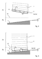
- the figure 2 represents the partially open roll-up screen.
- the final blade is positioned in the safety zone Zs. In this zone, due to the kinematics of the installation and its aging, the final blade tends to incline "naturally" by an angle ⁇ s with respect to the horizontal.
- the natural inclination of the final blade is substantially the same, all along the race, in this area. This natural inclination can be likened to an inclination of the blade at rest in this zone.
- the axis Xs-Xs' is noted, an axis representative of the orientation of the final blade when it is in this position of natural inclination. This axis is preferably stored as the first reference axis for zone Zs in accordance with the proposed method and described with reference to FIG. figure 4 .
- the figure 3 represents the closed roll-up screen.
- the final blade is positioned in the approach zone Za.
- the final blade is oriented according to the inclination ⁇ of the threshold.
- This axis is preferably stored as the second reference axis for zone Za. The storage of the reference axis is carried out in the same way as previously.
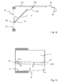
- the figure 4 represents an embodiment of a procedure for determining a reference axis used in the method that is the subject of the invention. Different stages of this embodiment make it possible to memorize the reference axis to be assigned to a specific zone of the race.
- a first step E110 the end of the screen, for example the final blade, is positioned at a specific position. This position must be representative of the position that the end occupies along the area in the sense that the inclination of the end in this position is taken as a reference for the obstacle detection.
- a second step E120 the installation, in particular the control unit or the detection means, determines a reference axis XX 'from the data measured by the detection means 8, for example fixed on the final plate 2.
- the detecting means measures its angular position. These measurements are recorded and serve to define the reference axis X-X '.
- the detection means such as an accelerometer, has at least two measurement axes or, at the very least, retranscribes its measurements along two axes X8 and Y8 in a plane parallel to the plane formed by the screen. once deployed.
- the reference axis X-X corresponds to the axis X8 at the moment when the final blade is in the specific position.
- the sensor on the final blade so that the axis X8 coincides at least substantially with the longitudinal orientation of the final blade. It is only a choice, another orientation of the detection means is also possible.
- the threshold value can be a pre-registered value, by default. This threshold value conditions the accuracy of the obstacle detection but must not be less than a limit, for example 0.5 °, so as not to trigger unwanted detections due to the mechanism of the installation (normal friction, frost. ..). To ensure good detection accuracy, the threshold value is less than 10 degrees, preferably less than 3 degrees.
- the system For safety zone Zs, as illustrated in figure 2 , the system must memorize the reference axis Xs-Xs'. The screen is therefore placed at a specific position such as the upper end position for example. From this position, the system determines the reference axis Xs-Xs'. Due to the alignment between the measuring direction of the sensor and the longitudinal axis of the end, the reference axis Xs-Xs' considered corresponds to the natural inclination of the final plate by an angle ⁇ s relative to horizontally.
- the figure 3 illustrates the memorization of the reference axis Xa-Xa 'for the approach zone Za.
- the specific position is the position of the final blade resting on the threshold.
- the reference axis Xa-Xa 'considered corresponds to the inclination of the final blade placed on the threshold of an angle ⁇ a with respect to the horizontal.
- the figure 5 represents a first embodiment of another procedure of the detection method which is the subject of the invention, this other procedure following the procedure described with reference to FIG. figure 4 .
- a third step E130 following a control command, the end of the screen is moved in a zone of the stroke of the screen.
- a fourth step E140 the position of the screen is analyzed to ensure that the end of the screen is always in the desired range of travel. If this end comes out of the zone, we go to an eighth step E180, otherwise we go to a fifth step E150.
- the angle of inclination of the end of the screen relative to the predetermined reference axis corresponding to the area traveled is measured.
- step E160 the measured angle is compared with the predetermined threshold value assigned to the traveled area. If the angle is less than the threshold angle, the screen continues its course, we go to step E140 with or without delay. If the angle is greater than this threshold angle, it goes to a seventh step E170.
- a security scenario is executed.
- An eighth step E180 makes it possible to exit this detection process once the end exceeds the zone concerned. This means that there has been no detection in this area. A message or feedback may be sent to the user to inform them. If the end of the screen enters a new zone, proceed to step E130, integrating the step E135 defined in FIG. figure 6 or proceed to a step E230 of the process defined in figure 7 . If the limit switch is reached, the detection process ends and a message or feedback can be sent to the user to inform him.
- the figure 6 represents step 135 added to the process described in figure 5 .
- step 135 following step E130 the system will consider the predetermined reference axis corresponding to the area to be scanned and the predetermined threshold value assigned to this area.
- the figure 7 represents a second embodiment of the procedure described in figure 5 .
- the main difference is that the measurement of the angle of inclination of the end of the screen is carried out only once, at a specific position of the zone considered.
- a step E230 the screen is moved to a specific position of the considered area of the race.
- this position corresponds to the closed position of the screen, when the end of the screen touches the threshold.
- a step E240 is analogous to step E150.
- a step E250 is analogous to step E160. If the measured angle is smaller than the considered threshold value, then one proceeds to a step E260. Otherwise, we go to a step E270.
- Step E260 consists of executing a security scenario that may be the same as that of step E170.
- Step E270 marks the end of the process in the case where the specific position has been correctly reached. Again, a message or feedback may be sent to the user to inform them.
- the Figures 8 to 11 represent the different configurations processed by the detection method according to the invention.
- the detection of an element between the threshold of an opening and the final blade is performed by an accelerometer along three axes.
- This detection means is advantageous, but it could be envisaged to use another means, such as an inclinometer.
- the accelerometer is attached near a side edge of the final blade.
- This particular arrangement also makes it possible to integrate, in this detection means, a sensor for detecting a zone limit as described above. Indeed, the magnets being at a slide, the detection means must be close to this slide, so close to a side edge of the final blade.
- the detection means is economical, simple to perform and install.
- the accelerometer could consider placing the accelerometer elsewhere on the final slide, in the center for example. For example, one can consider using a single accelerometer to determine the tilt position of the end of the screen and the vertical position of the end of the screen relative to the race. In this case, the position is obtained by double temporal integration of the acceleration values according to the direction of travel of the screen.
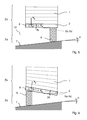
- the Figures 8 and 9 illustrate a detection in the safety zone Zs.
- the obstacle detection in this zone is obtained in several ways: by detecting the inclination of the final blade, and / or by detecting a variation of speed or acceleration of it.
- the figure 8 represents the first way of detection.
- An element such as an obstacle 9 occurs on the side of the final blade 2 where there is no detection means 8.
- the accelerometer does not detect a variation of speed, acceleration or, at least, not a significant variation.
- the obstacle can then be crushed more than safety standards require. Consequently, the use of an accelerometer considering only the variations of speed / acceleration according to the vertical does not make it possible to detect an obstacle and to react in accordance with the preceding safety standards.
- the accelerometer when the final blade will pivot, the accelerometer will measure, directly or indirectly, the angle ⁇ s corresponding to the inclination between the position of the final blade at the moment of the measurement and the reference axis Xs -Xs' defined before. This axis represents, as we have seen, the "natural" position of the blade in this zone. If this angle exceeds a predetermined threshold value assigned to this area, then the detection means transmits a detection signal to the processing unit that can initiate the execution of a security scenario.
- This scenario can be the opening of the screen or, at least, the relaxation of the effort on obstacle. Consequently, if the threshold value is correctly sized, the obstacle force can be limited. Be that as it may, this effort is less important than if it had finally been detected directly by a variation of speed or acceleration.
- the figure 9 represents the second way of detection.
- An obstacle 9 is placed under the detection means 8, on one side of the final blade 2.
- the speed and acceleration of the final blade fall abruptly.
- This variation is detected quickly by the accelerometer even before the natural inclination of the final blade can vary.
- the sensor transmits to the processing unit a signal corresponding to the detection of an obstacle.
- the processing unit then starts the execution of a security scenario that may be similar to the previous scenario.
- tilt detection is a complementary means of detection which, in principle, is not activated when the obstacle occurs under the sensor.
- this detection mode proves to be a security in case the variation of speed or acceleration is not detected.
- the detection of the inclination and its treatment are similar to those defined above. In this case, the obstacle force at the time of inclination detection would be greater than if it had been detected directly by a variation of speed or acceleration.
- the Figures 10 and 11 illustrate a detection in the approach area.
- the majority of garage door systems inhibit the triggering of a security scenario in case of obstacle detection.
- the reason for this inhibition is simple: when the final blade meets the threshold of the opening, the sensor considers the ground as an obstacle and causes the security scenario. This has the effect, at best a bad closing of the door and at worst the opening of the door. Consequently, in this zone, the sensor serves only to detect the end of travel of the door, but that does not necessarily mean that the door is closed properly. Indeed, the sensor can detect an obstacle instead of the ground. In this case, the system makes no distinction and considers that the door is closed, as shown by the Figures 10 and 11 .
- the passage of the final blade in this approach zone has the effect of inhibiting the triggering of a safety scenario in case detection of speed variation or acceleration by the accelerometer .
- the system maintains the triggering of a safety scenario in case of detection of the inclination of the final blade with respect to a reference axis corresponding to the orientation of the threshold, once the final blade has reached this threshold .
- the measurement of the inclination takes place while the screen is actually considered closed, it can be done after the system detects a limit switch, it can be by detection of the variation of speed or acceleration by the accelerometer, by counting at the level of the actuator ...
- the accelerometer will determine, directly or indirectly, the angle ⁇ a corresponding to the inclination between the position of the final blade, once the ground reaches, and the reference axis Xa-Xa ' defined before. It corresponds, in principle, to the inclination ⁇ of the ground. If this angle exceeds a predetermined threshold value assigned to this area, then the detection means transmits a detection signal to the processing unit that can initiate the execution of a security scenario.
- This scenario can be the opening of the screen or, at least, the relaxation of the effort on obstacle.
- the figure 10 represents the configuration of the screen at the moment when an obstacle 9, placed on the side of the final blade 2 where there is no sensor 8, is detected.
- the figure 11 represents the configuration of the screen at the moment when an obstacle 9 placed under the detection means 8, on one side of the final blade 2, is detected.
- FIG. 10 and 11 also illustrate the case of burglary detection.
- the obstacle 9 then represents the tool used for the break-in, for example, the end of a lever, type crowbar.
- the difference from the previous method is when the tilt measurement of the final blade is performed.
- a request from the user can be a request sent by a remote control either in order to launch a program of regular scanning of the inclination of the final blade, or for a verification punctual that there was no break-in.
- the sensor is awakened by the movement of the door while no order has been issued. If a break-in is detected, a signal is sent to the processing unit which can then trigger an alarm.
- the Figures 12 and 13 represent the method according to the invention applied to a tilting garage door, not overflowing.
- the door 11 is connected by an arm 133 to a carriage 132 movable along a rail 131.
- the carriage is driven in translation by a motor 14 through a chain or a belt not shown in the figure.
- the motor is controlled by a processing unit 15.
- the garage door closes an opening O.
- the lower end 12 of the door comes into contact with the threshold 17 of the opening.
- the detection means 18 or sensor is fixed on this end 12.
- the operation of the detection method and its configuration are the same as those described above. Note that the measurement of the inclination is made with respect to a plane parallel to the plane formed by the door, once closed. In this case, the angle of inclination is measured in a vertical plane.
- the detection means measures the inclination of the end of the screen relative to a fixed absolute reference
- the measured angle can be retranscribed relative to the reference axis considered.
- the retranscription can become the angle of inclination to compare.
- the determination of a value of the angle of inclination of the end of the screen means that the detection means evaluates the angular variation of the end of the screen relative to a reference frame. This determination generally requires a processing of the detection means measures to express them with respect to the reference axis considered.
- the transposed value corresponds to the value of the angle of inclination of the end of the screen. It directly reflects the angular variation of the end. Alternatively, it may be considered to transcribe the reference axis in the measurement frame. The analysis is less direct in this case.
- the measurement of the angle of inclination by the detection means must be understood in the broad sense and not only by a strict angular measurement.
- the angle can be deduced from the acceleration measurements ax and ay respectively according to two measurement directions, X and Y, for example. The angle is then defined by the ratio ax / ay.
Landscapes
- Engineering & Computer Science (AREA)
- Structural Engineering (AREA)
- Architecture (AREA)
- Civil Engineering (AREA)
- Operating, Guiding And Securing Of Roll- Type Closing Members (AREA)
- Power-Operated Mechanisms For Wings (AREA)
- Overhead Projectors And Projection Screens (AREA)
- Length Measuring Devices With Unspecified Measuring Means (AREA)
Applications Claiming Priority (1)
| Application Number | Priority Date | Filing Date | Title |
|---|---|---|---|
| FR0900529A FR2941991B1 (fr) | 2009-02-06 | 2009-02-06 | Procede de detection de la presence d'un element entre un seuil d'une ouverture et une extremite d'un ecran domotique motorise. |
Publications (3)
| Publication Number | Publication Date |
|---|---|
| EP2216478A2 true EP2216478A2 (de) | 2010-08-11 |
| EP2216478A3 EP2216478A3 (de) | 2012-08-22 |
| EP2216478B1 EP2216478B1 (de) | 2015-07-15 |
Family
ID=41165590
Family Applications (1)
| Application Number | Title | Priority Date | Filing Date |
|---|---|---|---|
| EP10152385.0A Not-in-force EP2216478B1 (de) | 2009-02-06 | 2010-02-02 | Anordnung zur Erkennung eines Hindernisses zwischen der Schwelle einer Gebäudeöffnung und dem Endstück einer motorisierten Abschirmung |
Country Status (4)
| Country | Link |
|---|---|
| EP (1) | EP2216478B1 (de) |
| JP (1) | JP5442478B2 (de) |
| CN (1) | CN101806921A (de) |
| FR (1) | FR2941991B1 (de) |
Cited By (3)
| Publication number | Priority date | Publication date | Assignee | Title |
|---|---|---|---|---|
| WO2012131114A1 (es) * | 2011-03-25 | 2012-10-04 | Gaviota Simbac, S.L. | Equipo de protección automatizada para toldos y voladizos frente a esfuerzos y causas externas |
| WO2013182663A1 (fr) * | 2012-06-07 | 2013-12-12 | Somfy Sas | Procede de commande d'une intallation equipee d'un actionneur rotatif et dispositif de commande associe |
| EP2905408A1 (de) | 2014-02-05 | 2015-08-12 | BFT SpA | Verfahren zum Erfassen von Hindernissen bei einem sich horizontal bewegenden oder um eine vertikale Achse schwenkenden Flügel |
Families Citing this family (8)
| Publication number | Priority date | Publication date | Assignee | Title |
|---|---|---|---|---|
| JP5603845B2 (ja) * | 2011-10-04 | 2014-10-08 | ソムフィ株式会社 | 電動シャッター装置の制御方法 |
| JP2017186807A (ja) * | 2016-04-06 | 2017-10-12 | 那須野 邦夫 | 電動ロールスクリーン装置及び傾斜検知センサー |
| DE102017102614A1 (de) * | 2017-02-09 | 2018-08-09 | Efaflex Tor- Und Sicherheitssysteme Gmbh & Co. Kg | Vorrichtung zur Erfassung des Absturzes eines Torblatts, System zur Erfassung des Absturzes eines Torblatts, sowie Verfahren zur Erfassung des Absturzes eines Torblatts |
| DE102017102599A1 (de) | 2017-02-09 | 2018-08-09 | Efaflex Tor- Und Sicherheitssysteme Gmbh & Co. Kg | Tor mit einem intelligenten Torblatt, welches eine elektrisch autarke Torblatteinrichtung aufweist, sowie Verfahren hierfür |
| AU2021217544A1 (en) | 2020-02-06 | 2022-09-15 | Assa Abloy Entrance Systems Ab | Sectional door operator system |
| FR3108459B1 (fr) * | 2020-03-20 | 2022-04-01 | Somfy Activites Sa | Procédé de détection d’un obstacle, actionneur électromécanique et installation de fermeture ou de protection solaire |
| US20240029550A1 (en) * | 2020-12-02 | 2024-01-25 | Michael Dalton Wilson | Smart remote system |
| EP4558691A1 (de) * | 2022-09-15 | 2025-05-28 | ASSA ABLOY Entrance Systems AB | Automatische bodenausrichtungskalibrierung für ein eingangssystem (i) |
Citations (5)
| Publication number | Priority date | Publication date | Assignee | Title |
|---|---|---|---|---|
| US5894267A (en) | 1996-03-29 | 1999-04-13 | Blair; William John | Tilt detector for roll-up door |
| DE20000682U1 (de) | 2000-01-17 | 2000-03-30 | Helmut Beyers GmbH, 41066 Mönchengladbach | Vorrichtung zur Steuerung der Bewegung einer Beschattungseinrichtung |
| EP1598518A1 (de) | 2004-05-20 | 2005-11-23 | P D Technology Limited | System zur Erkennung von Hindernissen |
| WO2005111960A2 (en) | 2004-05-11 | 2005-11-24 | Honeywell International, Inc. | Mems based garage door sensor |
| EP1970516A2 (de) | 2007-03-15 | 2008-09-17 | BALLAN S.p.A. | Vorrichtung zur Kontrolle der Sicherheit eines Rahmens während dessen Bewegung |
Family Cites Families (4)
| Publication number | Priority date | Publication date | Assignee | Title |
|---|---|---|---|---|
| JPH088239Y2 (ja) * | 1988-08-05 | 1996-03-06 | 三和シヤッター工業株式会社 | 建築用シヤツターの障害物検知装置 |
| JP2535483Y2 (ja) * | 1990-03-02 | 1997-05-14 | 文化シャッター株式会社 | 電動シャッターの障害物検知装置 |
| CN2570806Y (zh) * | 2002-04-30 | 2003-09-03 | 添诚资讯股份有限公司 | 电动卷门的状态信号检测装置 |
| JP2006124989A (ja) * | 2004-10-27 | 2006-05-18 | Bunka Shutter Co Ltd | 開閉装置 |
-
2009
- 2009-02-06 FR FR0900529A patent/FR2941991B1/fr not_active Expired - Fee Related
-
2010
- 2010-02-02 EP EP10152385.0A patent/EP2216478B1/de not_active Not-in-force
- 2010-02-05 CN CN201010113615A patent/CN101806921A/zh active Pending
- 2010-02-05 JP JP2010024151A patent/JP5442478B2/ja not_active Expired - Fee Related
Patent Citations (5)
| Publication number | Priority date | Publication date | Assignee | Title |
|---|---|---|---|---|
| US5894267A (en) | 1996-03-29 | 1999-04-13 | Blair; William John | Tilt detector for roll-up door |
| DE20000682U1 (de) | 2000-01-17 | 2000-03-30 | Helmut Beyers GmbH, 41066 Mönchengladbach | Vorrichtung zur Steuerung der Bewegung einer Beschattungseinrichtung |
| WO2005111960A2 (en) | 2004-05-11 | 2005-11-24 | Honeywell International, Inc. | Mems based garage door sensor |
| EP1598518A1 (de) | 2004-05-20 | 2005-11-23 | P D Technology Limited | System zur Erkennung von Hindernissen |
| EP1970516A2 (de) | 2007-03-15 | 2008-09-17 | BALLAN S.p.A. | Vorrichtung zur Kontrolle der Sicherheit eines Rahmens während dessen Bewegung |
Cited By (4)
| Publication number | Priority date | Publication date | Assignee | Title |
|---|---|---|---|---|
| WO2012131114A1 (es) * | 2011-03-25 | 2012-10-04 | Gaviota Simbac, S.L. | Equipo de protección automatizada para toldos y voladizos frente a esfuerzos y causas externas |
| WO2013182663A1 (fr) * | 2012-06-07 | 2013-12-12 | Somfy Sas | Procede de commande d'une intallation equipee d'un actionneur rotatif et dispositif de commande associe |
| FR2991709A1 (fr) * | 2012-06-07 | 2013-12-13 | Somfy Sas | Procede de commande d'une installation equipee d'un actionneur rotatif et dispositif de commande associe |
| EP2905408A1 (de) | 2014-02-05 | 2015-08-12 | BFT SpA | Verfahren zum Erfassen von Hindernissen bei einem sich horizontal bewegenden oder um eine vertikale Achse schwenkenden Flügel |
Also Published As
| Publication number | Publication date |
|---|---|
| FR2941991B1 (fr) | 2011-02-25 |
| EP2216478B1 (de) | 2015-07-15 |
| JP2010180696A (ja) | 2010-08-19 |
| CN101806921A (zh) | 2010-08-18 |
| EP2216478A3 (de) | 2012-08-22 |
| FR2941991A1 (fr) | 2010-08-13 |
| JP5442478B2 (ja) | 2014-03-12 |
Similar Documents
| Publication | Publication Date | Title |
|---|---|---|
| EP2216478B1 (de) | Anordnung zur Erkennung eines Hindernisses zwischen der Schwelle einer Gebäudeöffnung und dem Endstück einer motorisierten Abschirmung | |
| EP2160501B1 (de) | Sicheres verfahren zum automatischen schliessen einer kraftfahrzeugheckklappe | |
| EP2075401B1 (de) | Method of adjusting a motorised solar protection installation not comprising an end-stop. | |
| EP1497702B1 (de) | Verfahren zur ermittlung einer durchbrechenden lage eines roll-ladens | |
| EP2067922A1 (de) | Rollladensystem | |
| CH701707B1 (fr) | Procédé de fonctionnement d'un système de commande d'un moteur électrique d'un actionneur de store. | |
| EP1451654A1 (de) | Verfahren zum anschlaglernen und einrichtung dafür | |
| FR3069008A1 (fr) | Fenetre coulissante pour un batiment et installation domotique comprenant une telle fenetre coulissante, ainsi que procede de commande associe | |
| EP3530857B1 (de) | Betriebssteuerungsverfahren einer motorisierten antriebsvorrichtung eines fensters für ein gebäude, entsprechendes fenster und entsprechende haustechnikanlage | |
| EP3470616B1 (de) | Verfahren zur automatischen regulierung einer mit einem blockiersystem ausgestatteten rollladenanlage | |
| WO2012007448A1 (fr) | Procede de fonctionnement d'un dispositif comprenant un actionneur electromecanique pilotant un element mobile de fermeture ou d'occultation d'une ouverture dans un batiment | |
| EP2015156B1 (de) | Verfahren zum Betrieb einer Heiminstallation und Heiminstallation zur Durchführung dieses Verfahrens | |
| EP4008866B1 (de) | Verfahren zur betriebssteuerung einer motorisierten antriebsvorrichtung eines schiebefensters für ein gebäude, entsprechendes fenster und entsprechende haustechnikanlage | |
| EP2441913A1 (de) | Blockiervorrichtung einer Lastschiene eines Schirms, und Schließ- oder Sonnenschutzinstallation, die mit einer solchen Blockiervorrichtung ausgestattet ist | |
| EP2554776B1 (de) | Lernprozess einer bestimmten Position eines elektrischen Stellglieds, das zur Steuerung eines Haushaltsgeräts bestimmt ist | |
| EP2093372B1 (de) | Betriebsverfahren einer Steuerungseinheit eines elektomechanischen Betätigungsglieds für die Bedienung eines Schutzschirms | |
| FR2942051A1 (fr) | Procede de restauration des reglages de fins de course | |
| EP2118397B1 (de) | Hausautomatisierungssensor mit einem beschleunigungsmesser, verfahren zur konfiguration desselben und einstellwerkzeug zur durchführung des verfahrens | |
| FR3057599A1 (fr) | Procede de commande en fonctionnement d'un dispositif d'entrainement motorise d'une fenetre coulissante pour un batiment, dispositif d'entrainement motorise et fenetre coulissante associes | |
| EP2725182A1 (de) | Funktionsverfahren eines Betätigungsstellglieds eines beweglichen Elements einer Haustechnikanlage, und Stellglied, das nach diesem Verfahren funktioniert | |
| EP1488294B1 (de) | Verfahren zur steuerung einer walzenblende oder ähnlichem | |
| EP2450761B1 (de) | Gerät und Verfahren zum Ansteuern einer Schließvorrichtung umfassend einen Schrittmotor. | |
| EP1441100A1 (de) | Verfahren zum automatischen schliessen eines Drehflügels, automatischer Schliessmechanismus und Schliesseinrichtung oder Sonnenschutzeinrichtung mit einem solchen Mechanismus | |
| EP3597848B1 (de) | Steuerungsverfahren von hindernissen in einer anlage, die die bewegungen von öffnungsflügeln oder klappläden kontrolliert | |
| FR3077086A1 (fr) | Gestion du deplacement combine de deux vantaux motorises en cas de rencontre d'un obstacle par l'un des vantaux. |
Legal Events
| Date | Code | Title | Description |
|---|---|---|---|
| PUAI | Public reference made under article 153(3) epc to a published international application that has entered the european phase |
Free format text: ORIGINAL CODE: 0009012 |
|
| AK | Designated contracting states |
Kind code of ref document: A2 Designated state(s): AT BE BG CH CY CZ DE DK EE ES FI FR GB GR HR HU IE IS IT LI LT LU LV MC MK MT NL NO PL PT RO SE SI SK SM TR |
|
| PUAL | Search report despatched |
Free format text: ORIGINAL CODE: 0009013 |
|
| AK | Designated contracting states |
Kind code of ref document: A3 Designated state(s): AT BE BG CH CY CZ DE DK EE ES FI FR GB GR HR HU IE IS IT LI LT LU LV MC MK MT NL NO PL PT RO SE SI SK SM TR |
|
| RIC1 | Information provided on ipc code assigned before grant |
Ipc: E05F 15/20 20060101ALI20120713BHEP Ipc: E06B 9/88 20060101AFI20120713BHEP Ipc: E04F 10/06 20060101ALN20120713BHEP Ipc: E06B 9/17 20060101ALI20120713BHEP |
|
| 17P | Request for examination filed |
Effective date: 20130220 |
|
| RIC1 | Information provided on ipc code assigned before grant |
Ipc: E06B 9/88 20060101AFI20130307BHEP Ipc: E04F 10/06 20060101ALN20130307BHEP Ipc: E06B 9/17 20060101ALI20130307BHEP Ipc: E05F 15/20 20060101ALI20130307BHEP |
|
| 17Q | First examination report despatched |
Effective date: 20130611 |
|
| RIC1 | Information provided on ipc code assigned before grant |
Ipc: E06B 9/88 20060101AFI20140318BHEP Ipc: E05F 15/20 20060101ALI20140318BHEP Ipc: E06B 9/17 20060101ALI20140318BHEP Ipc: E04F 10/06 20060101ALN20140318BHEP |
|
| GRAP | Despatch of communication of intention to grant a patent |
Free format text: ORIGINAL CODE: EPIDOSNIGR1 |
|
| RIC1 | Information provided on ipc code assigned before grant |
Ipc: E06B 9/88 20060101AFI20141210BHEP Ipc: E06B 9/17 20060101ALI20141210BHEP Ipc: E04F 10/06 20060101ALN20141210BHEP Ipc: E05F 15/20 00000000ALI20141210BHEP |
|
| INTG | Intention to grant announced |
Effective date: 20150113 |
|
| GRAS | Grant fee paid |
Free format text: ORIGINAL CODE: EPIDOSNIGR3 |
|
| REG | Reference to a national code |
Ref country code: DE Ref legal event code: R079 Ref document number: 602010025855 Country of ref document: DE Free format text: PREVIOUS MAIN CLASS: E06B0009170000 Ipc: E06B0009880000 |
|
| GRAA | (expected) grant |
Free format text: ORIGINAL CODE: 0009210 |
|
| AK | Designated contracting states |
Kind code of ref document: B1 Designated state(s): AT BE BG CH CY CZ DE DK EE ES FI FR GB GR HR HU IE IS IT LI LT LU LV MC MK MT NL NO PL PT RO SE SI SK SM TR |
|
| REG | Reference to a national code |
Ref country code: CH Ref legal event code: EP Ref country code: GB Ref legal event code: FG4D Free format text: NOT ENGLISH |
|
| RIC1 | Information provided on ipc code assigned before grant |
Ipc: E06B 9/17 20060101ALI20150608BHEP Ipc: E06B 9/88 20060101AFI20150608BHEP |
|
| REG | Reference to a national code |
Ref country code: IE Ref legal event code: FG4D Free format text: LANGUAGE OF EP DOCUMENT: FRENCH |
|
| REG | Reference to a national code |
Ref country code: AT Ref legal event code: REF Ref document number: 736906 Country of ref document: AT Kind code of ref document: T Effective date: 20150815 |
|
| REG | Reference to a national code |
Ref country code: DE Ref legal event code: R096 Ref document number: 602010025855 Country of ref document: DE |
|
| REG | Reference to a national code |
Ref country code: AT Ref legal event code: MK05 Ref document number: 736906 Country of ref document: AT Kind code of ref document: T Effective date: 20150715 |
|
| REG | Reference to a national code |
Ref country code: NL Ref legal event code: MP Effective date: 20150715 |
|
| REG | Reference to a national code |
Ref country code: LT Ref legal event code: MG4D |
|
| PG25 | Lapsed in a contracting state [announced via postgrant information from national office to epo] |
Ref country code: LT Free format text: LAPSE BECAUSE OF FAILURE TO SUBMIT A TRANSLATION OF THE DESCRIPTION OR TO PAY THE FEE WITHIN THE PRESCRIBED TIME-LIMIT Effective date: 20150715 Ref country code: LV Free format text: LAPSE BECAUSE OF FAILURE TO SUBMIT A TRANSLATION OF THE DESCRIPTION OR TO PAY THE FEE WITHIN THE PRESCRIBED TIME-LIMIT Effective date: 20150715 Ref country code: FI Free format text: LAPSE BECAUSE OF FAILURE TO SUBMIT A TRANSLATION OF THE DESCRIPTION OR TO PAY THE FEE WITHIN THE PRESCRIBED TIME-LIMIT Effective date: 20150715 Ref country code: NO Free format text: LAPSE BECAUSE OF FAILURE TO SUBMIT A TRANSLATION OF THE DESCRIPTION OR TO PAY THE FEE WITHIN THE PRESCRIBED TIME-LIMIT Effective date: 20151015 Ref country code: GR Free format text: LAPSE BECAUSE OF FAILURE TO SUBMIT A TRANSLATION OF THE DESCRIPTION OR TO PAY THE FEE WITHIN THE PRESCRIBED TIME-LIMIT Effective date: 20151016 |
|
| PG25 | Lapsed in a contracting state [announced via postgrant information from national office to epo] |
Ref country code: AT Free format text: LAPSE BECAUSE OF FAILURE TO SUBMIT A TRANSLATION OF THE DESCRIPTION OR TO PAY THE FEE WITHIN THE PRESCRIBED TIME-LIMIT Effective date: 20150715 Ref country code: PT Free format text: LAPSE BECAUSE OF FAILURE TO SUBMIT A TRANSLATION OF THE DESCRIPTION OR TO PAY THE FEE WITHIN THE PRESCRIBED TIME-LIMIT Effective date: 20151116 Ref country code: SE Free format text: LAPSE BECAUSE OF FAILURE TO SUBMIT A TRANSLATION OF THE DESCRIPTION OR TO PAY THE FEE WITHIN THE PRESCRIBED TIME-LIMIT Effective date: 20150715 Ref country code: HR Free format text: LAPSE BECAUSE OF FAILURE TO SUBMIT A TRANSLATION OF THE DESCRIPTION OR TO PAY THE FEE WITHIN THE PRESCRIBED TIME-LIMIT Effective date: 20150715 Ref country code: ES Free format text: LAPSE BECAUSE OF FAILURE TO SUBMIT A TRANSLATION OF THE DESCRIPTION OR TO PAY THE FEE WITHIN THE PRESCRIBED TIME-LIMIT Effective date: 20150715 Ref country code: PL Free format text: LAPSE BECAUSE OF FAILURE TO SUBMIT A TRANSLATION OF THE DESCRIPTION OR TO PAY THE FEE WITHIN THE PRESCRIBED TIME-LIMIT Effective date: 20150715 |
|
| REG | Reference to a national code |
Ref country code: FR Ref legal event code: PLFP Year of fee payment: 7 |
|
| REG | Reference to a national code |
Ref country code: DE Ref legal event code: R097 Ref document number: 602010025855 Country of ref document: DE |
|
| PG25 | Lapsed in a contracting state [announced via postgrant information from national office to epo] |
Ref country code: SK Free format text: LAPSE BECAUSE OF FAILURE TO SUBMIT A TRANSLATION OF THE DESCRIPTION OR TO PAY THE FEE WITHIN THE PRESCRIBED TIME-LIMIT Effective date: 20150715 Ref country code: DK Free format text: LAPSE BECAUSE OF FAILURE TO SUBMIT A TRANSLATION OF THE DESCRIPTION OR TO PAY THE FEE WITHIN THE PRESCRIBED TIME-LIMIT Effective date: 20150715 Ref country code: CZ Free format text: LAPSE BECAUSE OF FAILURE TO SUBMIT A TRANSLATION OF THE DESCRIPTION OR TO PAY THE FEE WITHIN THE PRESCRIBED TIME-LIMIT Effective date: 20150715 Ref country code: IT Free format text: LAPSE BECAUSE OF FAILURE TO SUBMIT A TRANSLATION OF THE DESCRIPTION OR TO PAY THE FEE WITHIN THE PRESCRIBED TIME-LIMIT Effective date: 20150715 Ref country code: EE Free format text: LAPSE BECAUSE OF FAILURE TO SUBMIT A TRANSLATION OF THE DESCRIPTION OR TO PAY THE FEE WITHIN THE PRESCRIBED TIME-LIMIT Effective date: 20150715 |
|
| PLBE | No opposition filed within time limit |
Free format text: ORIGINAL CODE: 0009261 |
|
| STAA | Information on the status of an ep patent application or granted ep patent |
Free format text: STATUS: NO OPPOSITION FILED WITHIN TIME LIMIT |
|
| PG25 | Lapsed in a contracting state [announced via postgrant information from national office to epo] |
Ref country code: BE Free format text: LAPSE BECAUSE OF NON-PAYMENT OF DUE FEES Effective date: 20160229 Ref country code: RO Free format text: LAPSE BECAUSE OF FAILURE TO SUBMIT A TRANSLATION OF THE DESCRIPTION OR TO PAY THE FEE WITHIN THE PRESCRIBED TIME-LIMIT Effective date: 20150715 |
|
| 26N | No opposition filed |
Effective date: 20160418 |
|
| PG25 | Lapsed in a contracting state [announced via postgrant information from national office to epo] |
Ref country code: IS Free format text: LAPSE BECAUSE OF FAILURE TO SUBMIT A TRANSLATION OF THE DESCRIPTION OR TO PAY THE FEE WITHIN THE PRESCRIBED TIME-LIMIT Effective date: 20150715 |
|
| PG25 | Lapsed in a contracting state [announced via postgrant information from national office to epo] |
Ref country code: SI Free format text: LAPSE BECAUSE OF FAILURE TO SUBMIT A TRANSLATION OF THE DESCRIPTION OR TO PAY THE FEE WITHIN THE PRESCRIBED TIME-LIMIT Effective date: 20150715 |
|
| PG25 | Lapsed in a contracting state [announced via postgrant information from national office to epo] |
Ref country code: LU Free format text: LAPSE BECAUSE OF FAILURE TO SUBMIT A TRANSLATION OF THE DESCRIPTION OR TO PAY THE FEE WITHIN THE PRESCRIBED TIME-LIMIT Effective date: 20160202 Ref country code: MC Free format text: LAPSE BECAUSE OF FAILURE TO SUBMIT A TRANSLATION OF THE DESCRIPTION OR TO PAY THE FEE WITHIN THE PRESCRIBED TIME-LIMIT Effective date: 20150715 |
|
| REG | Reference to a national code |
Ref country code: CH Ref legal event code: PL |
|
| PG25 | Lapsed in a contracting state [announced via postgrant information from national office to epo] |
Ref country code: CH Free format text: LAPSE BECAUSE OF NON-PAYMENT OF DUE FEES Effective date: 20160229 Ref country code: LI Free format text: LAPSE BECAUSE OF NON-PAYMENT OF DUE FEES Effective date: 20160229 |
|
| REG | Reference to a national code |
Ref country code: IE Ref legal event code: MM4A |
|
| PG25 | Lapsed in a contracting state [announced via postgrant information from national office to epo] |
Ref country code: IE Free format text: LAPSE BECAUSE OF NON-PAYMENT OF DUE FEES Effective date: 20160202 |
|
| REG | Reference to a national code |
Ref country code: FR Ref legal event code: PLFP Year of fee payment: 8 |
|
| PG25 | Lapsed in a contracting state [announced via postgrant information from national office to epo] |
Ref country code: NL Free format text: LAPSE BECAUSE OF FAILURE TO SUBMIT A TRANSLATION OF THE DESCRIPTION OR TO PAY THE FEE WITHIN THE PRESCRIBED TIME-LIMIT Effective date: 20150715 |
|
| PG25 | Lapsed in a contracting state [announced via postgrant information from national office to epo] |
Ref country code: MT Free format text: LAPSE BECAUSE OF FAILURE TO SUBMIT A TRANSLATION OF THE DESCRIPTION OR TO PAY THE FEE WITHIN THE PRESCRIBED TIME-LIMIT Effective date: 20150715 |
|
| REG | Reference to a national code |
Ref country code: FR Ref legal event code: PLFP Year of fee payment: 9 |
|
| PG25 | Lapsed in a contracting state [announced via postgrant information from national office to epo] |
Ref country code: SM Free format text: LAPSE BECAUSE OF FAILURE TO SUBMIT A TRANSLATION OF THE DESCRIPTION OR TO PAY THE FEE WITHIN THE PRESCRIBED TIME-LIMIT Effective date: 20150715 Ref country code: HU Free format text: LAPSE BECAUSE OF FAILURE TO SUBMIT A TRANSLATION OF THE DESCRIPTION OR TO PAY THE FEE WITHIN THE PRESCRIBED TIME-LIMIT; INVALID AB INITIO Effective date: 20100202 Ref country code: CY Free format text: LAPSE BECAUSE OF FAILURE TO SUBMIT A TRANSLATION OF THE DESCRIPTION OR TO PAY THE FEE WITHIN THE PRESCRIBED TIME-LIMIT Effective date: 20150715 |
|
| PG25 | Lapsed in a contracting state [announced via postgrant information from national office to epo] |
Ref country code: TR Free format text: LAPSE BECAUSE OF FAILURE TO SUBMIT A TRANSLATION OF THE DESCRIPTION OR TO PAY THE FEE WITHIN THE PRESCRIBED TIME-LIMIT Effective date: 20150715 Ref country code: MK Free format text: LAPSE BECAUSE OF FAILURE TO SUBMIT A TRANSLATION OF THE DESCRIPTION OR TO PAY THE FEE WITHIN THE PRESCRIBED TIME-LIMIT Effective date: 20150715 |
|
| PG25 | Lapsed in a contracting state [announced via postgrant information from national office to epo] |
Ref country code: BG Free format text: LAPSE BECAUSE OF FAILURE TO SUBMIT A TRANSLATION OF THE DESCRIPTION OR TO PAY THE FEE WITHIN THE PRESCRIBED TIME-LIMIT Effective date: 20150715 |
|
| REG | Reference to a national code |
Ref country code: DE Ref legal event code: R082 Ref document number: 602010025855 Country of ref document: DE Representative=s name: PATENTANWAELTE OSTRIGA, SONNET, WIRTHS & VORWE, DE Ref country code: DE Ref legal event code: R081 Ref document number: 602010025855 Country of ref document: DE Owner name: SOMFY ACTIVITES SA, FR Free format text: FORMER OWNER: SOMFY SAS, CLUSES, FR |
|
| PGFP | Annual fee paid to national office [announced via postgrant information from national office to epo] |
Ref country code: GB Payment date: 20220218 Year of fee payment: 13 Ref country code: DE Payment date: 20220214 Year of fee payment: 13 |
|
| PGFP | Annual fee paid to national office [announced via postgrant information from national office to epo] |
Ref country code: FR Payment date: 20220223 Year of fee payment: 13 |
|
| REG | Reference to a national code |
Ref country code: DE Ref legal event code: R119 Ref document number: 602010025855 Country of ref document: DE |
|
| GBPC | Gb: european patent ceased through non-payment of renewal fee |
Effective date: 20230202 |
|
| PG25 | Lapsed in a contracting state [announced via postgrant information from national office to epo] |
Ref country code: GB Free format text: LAPSE BECAUSE OF NON-PAYMENT OF DUE FEES Effective date: 20230202 |
|
| PG25 | Lapsed in a contracting state [announced via postgrant information from national office to epo] |
Ref country code: GB Free format text: LAPSE BECAUSE OF NON-PAYMENT OF DUE FEES Effective date: 20230202 Ref country code: FR Free format text: LAPSE BECAUSE OF NON-PAYMENT OF DUE FEES Effective date: 20230228 Ref country code: DE Free format text: LAPSE BECAUSE OF NON-PAYMENT OF DUE FEES Effective date: 20230901 |