EP2213903B1 - Disk brake - Google Patents
Disk brake Download PDFInfo
- Publication number
- EP2213903B1 EP2213903B1 EP10151923A EP10151923A EP2213903B1 EP 2213903 B1 EP2213903 B1 EP 2213903B1 EP 10151923 A EP10151923 A EP 10151923A EP 10151923 A EP10151923 A EP 10151923A EP 2213903 B1 EP2213903 B1 EP 2213903B1
- Authority
- EP
- European Patent Office
- Prior art keywords
- surface portion
- sealing groove
- cylinder bore
- piston
- lateral surface
- Prior art date
- Legal status (The legal status is an assumption and is not a legal conclusion. Google has not performed a legal analysis and makes no representation as to the accuracy of the status listed.)
- Not-in-force
Links
Images


Classifications
-
- F—MECHANICAL ENGINEERING; LIGHTING; HEATING; WEAPONS; BLASTING
- F16—ENGINEERING ELEMENTS AND UNITS; GENERAL MEASURES FOR PRODUCING AND MAINTAINING EFFECTIVE FUNCTIONING OF MACHINES OR INSTALLATIONS; THERMAL INSULATION IN GENERAL
- F16D—COUPLINGS FOR TRANSMITTING ROTATION; CLUTCHES; BRAKES
- F16D65/00—Parts or details
- F16D65/14—Actuating mechanisms for brakes; Means for initiating operation at a predetermined position
- F16D65/16—Actuating mechanisms for brakes; Means for initiating operation at a predetermined position arranged in or on the brake
- F16D65/18—Actuating mechanisms for brakes; Means for initiating operation at a predetermined position arranged in or on the brake adapted for drawing members together, e.g. for disc brakes
-
- F—MECHANICAL ENGINEERING; LIGHTING; HEATING; WEAPONS; BLASTING
- F16—ENGINEERING ELEMENTS AND UNITS; GENERAL MEASURES FOR PRODUCING AND MAINTAINING EFFECTIVE FUNCTIONING OF MACHINES OR INSTALLATIONS; THERMAL INSULATION IN GENERAL
- F16J—PISTONS; CYLINDERS; SEALINGS
- F16J15/00—Sealings
- F16J15/16—Sealings between relatively-moving surfaces
- F16J15/32—Sealings between relatively-moving surfaces with elastic sealings, e.g. O-rings
- F16J15/3204—Sealings between relatively-moving surfaces with elastic sealings, e.g. O-rings with at least one lip
-
- F—MECHANICAL ENGINEERING; LIGHTING; HEATING; WEAPONS; BLASTING
- F16—ENGINEERING ELEMENTS AND UNITS; GENERAL MEASURES FOR PRODUCING AND MAINTAINING EFFECTIVE FUNCTIONING OF MACHINES OR INSTALLATIONS; THERMAL INSULATION IN GENERAL
- F16J—PISTONS; CYLINDERS; SEALINGS
- F16J15/00—Sealings
- F16J15/56—Other sealings for reciprocating rods
-
- F—MECHANICAL ENGINEERING; LIGHTING; HEATING; WEAPONS; BLASTING
- F16—ENGINEERING ELEMENTS AND UNITS; GENERAL MEASURES FOR PRODUCING AND MAINTAINING EFFECTIVE FUNCTIONING OF MACHINES OR INSTALLATIONS; THERMAL INSULATION IN GENERAL
- F16D—COUPLINGS FOR TRANSMITTING ROTATION; CLUTCHES; BRAKES
- F16D2121/00—Type of actuator operation force
- F16D2121/02—Fluid pressure
-
- F—MECHANICAL ENGINEERING; LIGHTING; HEATING; WEAPONS; BLASTING
- F16—ENGINEERING ELEMENTS AND UNITS; GENERAL MEASURES FOR PRODUCING AND MAINTAINING EFFECTIVE FUNCTIONING OF MACHINES OR INSTALLATIONS; THERMAL INSULATION IN GENERAL
- F16D—COUPLINGS FOR TRANSMITTING ROTATION; CLUTCHES; BRAKES
- F16D2125/00—Components of actuators
- F16D2125/02—Fluid-pressure mechanisms
- F16D2125/06—Pistons
-
- F—MECHANICAL ENGINEERING; LIGHTING; HEATING; WEAPONS; BLASTING
- F16—ENGINEERING ELEMENTS AND UNITS; GENERAL MEASURES FOR PRODUCING AND MAINTAINING EFFECTIVE FUNCTIONING OF MACHINES OR INSTALLATIONS; THERMAL INSULATION IN GENERAL
- F16D—COUPLINGS FOR TRANSMITTING ROTATION; CLUTCHES; BRAKES
- F16D2127/00—Auxiliary mechanisms
- F16D2127/02—Release mechanisms
Definitions
- the present invention relates to a hydraulic disk brake.
- the hydraulic disk brake comprises: a disk rotor that rotates together with a wheel; a pair of brake pads arranged at each side of the disk rotor; a caliper provided with a cylinder bore that faces the rear side of the brake pad, the caliper being supported on a side of a vehicle body; and a piston that is slidably inserted into the cylinder bore so as to press the brake pads to the disk rotor.
- the piston moves forward with hydraulic pressure supplied from a hydraulic pressure source such as a master cylinder to the cylinder bore, whereby braking force will be generated by pressing the brake pads against the disk rotor.
- Patent Document 1 a piston seal that is rectangular in section and made of an elastic material such as EPDM (ethylene-propylene rubber) is adapted to seal between a cylinder bore and a piston of a hydraulic disk brake.
- EPDM ethylene-propylene rubber
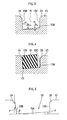
- a piston seal 1 is fitted into a sealing groove 3, the sealing groove 3 being an inner periphery groove in a rectangular section and being formed on an inner periphery of a cylinder bore 2. Further, the piston seal 1 is attached to an external periphery of a piston 4 so as to seal between the cylinder bore 2 and the piston 4.
- its bottom surface portion 3A is formed so as to make a diameter of the sealing groove 3 expanded as moving toward an opening of the cylinder bore 2 (left side in FIG. 10 ) whereby the sealing groove 3 is formed approximately in a trapezoidal section.
- dimension of the sealing groove 3 in an axial direction is formed to be larger than the one of the piston seal 1.
- the piston 4 moves forward by hydraulic pressure supplied into the cylinder bore 2, whereby the piston seal 1 is elastically deformed in a left-sided direction along the chamfered portion 5.
- the piston 4 is adapted to move backward in a right-sided direction due to a rollback function to which the elastic quality of the piston seal 1 is participated.
- the piston 4 is adapted to move forward while braking is applied only for an amount where the brake pads are worn down.
- the piston 4 is adapted to slide relative to the piston seal 1. This makes possible to compensate the brake pads' wear making a pad clearance adjustable to a constant amount.
- Hydraulically actuated full-lining disc brakes on off-road motor vehicles must, in the most difficult conditions of use, have a high operational reliability and, at the same time, be easy to service and maintain, in order to be able to carry out any work with simple means.
- the hydraulically actuated full-lining disc brake comprises a single-part hydraulic housing in which there are integrated, in a manner distributed uniformly over the circumference, a plurality of through-passage bores in which axially movable pistons are guided.
- the sealing and restoring of the deflected pistons take place via prestressed radial sealing rings.
- a disk brake comprising: a brake pad that is arranged on each side of a disk rotor; a piston that presses the brake pad to the disk rotor; a cylinder bore into which the piston is installed; an annular sealing groove that is formed on an inner periphery of the cylinder bore; and a piston seal that is rectangular in section and is fitted into the sealing groove so as to seal a portion defined between the piston and the cylinder bore, wherein the sealing groove is composed of: a bottom surface portion inclined as the sealing groove expands its diameter as moving toward an opening of the cylinder bore; a lateral surface portion that extends from one end of the bottom surface portion, the one end being a side where the sealing groove has the maximum diameter; and a chamfered portion that is provided between the lateral surface portion and the inner periphery of the cylinder bore, the chamfered portion being formed as the opening of the sealing groove is expanded in an axial direction of the cylinder bore, and wherein an inclined angle of the bottom surface portion relative to an axi
- a disk brake comprising: a brake pad that is arranged on each side of a disk rotor; a piston that presses at least one of the brake pads to the disk rotor; a cylinder bore into which the piston is slidably installed; a sealing groove that is formed on an inner periphery of the cylinder bore; and a piston seal that is rectangular in section and fitted into the sealing groove so as to seal a portion defined between the piston and the cylinder bore, wherein the sealing groove is provided with a bottom surface portion that is inclined at angle of 2 to 8 degrees relative to a line parallel to a central line of the cylinder bore in an axial direction as a diameter of the sealing groove is expanded as moving toward an opening of the cylinder bore; the sealing groove is also provided with a lateral surface portion formed on a side where the cylinder bore is opened, the lateral surface portion being set to 0 degree relative to a surface that is orthogonal to the central line of the cylinder bore in an axial direction, or being set to angle of
- a disk brake comprising: a brake pad that is arranged on each side of a disk rotor; a piston that presses the brake pad to the disk rotor; a cylinder bore into which the piston is slidably installed; an annular sealing groove that is formed on an inner periphery of the cylinder bore; and a piston seal that is rectangular in section and is fitted into an opening of the sealing groove so as to seal a portion defined between the piston and the cylinder bore, wherein the sealing groove is composed of: a bottom surface portion inclined as the sealing groove expands its diameter as moving toward an opening of the cylinder bore; a lateral surface portion that extends from one end of the bottom surface portion, the one end being a side where the sealing groove has the maximum diameter; and a chamfered portion that is provided between the lateral surface portion and the inner periphery of the cylinder bore, the chamfered portion being formed as the opening of the sealing groove is expanded in an axial direction of the cylinder bore, and wherein the lateral
- a disk brake 7 is categorized into a floating-caliper disk brake, and comprises: a disk rotor 8 that is rotated together with wheels; a carrier 9 that is fixed on a side of a vehicle body; a caliper main body 10 that is movably supported in an axial direction of the disk rotor 8 relative to the carrier 9; and a pair of brake pads 11A, 11B that is arranged at each side of the disk rotor 8 and movably supported in an axial direction of the disk rotor 8 by means of the carrier 9.
- the caliper main body 10 is provided with a cylinder bore 13 that faces one of the brake pads, the brake pad 11A. the caliper main body 10 being also integrally formed with a claw portion 14 that overstrides the disk rotor 8 so as to face the other brake pad, the brake pad 11B.
- a sealing groove 15 is provided on an inner peripheral surface of and on an opening side of the cylinder bore 13, the sealing groove 15 being formed externally in a radial direction of the disk rotor 8 so as to form an annular concavity.
- a piston seal (or sealing member) 16 is installed into the sealing groove 15, and a piston 17 is slidably inserted into the cylinder bore 13 through the piston seal 16. Further, a dust boot 12 is provided between a marginal opening of the cylinder bore 13 and the piston 17.
- a port 18 for supplying hydraulic pressure into the cylinder bore 13 is provided on a bottom-sided portion of the cylinder bore 13, a port 18 for supplying hydraulic pressure into the cylinder bore 13 is provided.
- the piston 17 moves forward so as to press the brake pad 11A to the disk rotor 8.
- the caliper main body 10 With its counterforce, the caliper main body 10 is adapted to move whereby the claw portion 14 presses the other side of the brake pad, the brake pad 11B to the disk rotor 8 so as to produce braking force.
- the piston 17 moves backward, whereby the brake pads 11A, 11B will move away from the disk rotor 8 so as to release the braking force.
- sealing groove 15 of the caliper main body 10 and the piston seal 16 With reference to FIG. 1 .
- its dimension in an axial direction of the disk rotor 8 is set to be larger than the piston seal 16 while its bottom surface portion 15A inclines as that a diameter of the sealing groove 15 becomes expanded as moving toward an opening of the cylinder bore 13 (left side in FIG. 1 ) so as to form a tapered configuration.
- FIG. 1 shows the sealing groove 15 of the caliper main body 10 and the piston seal 16 with reference to FIG. 1 .
- an inclined angle ⁇ of the bottom surface portion 15A in an axial direction of the cylinder bore 13 is set to 5 degrees while an angle ⁇ defined between the bottom surface portion 15A and a lateral surface portion 15B placed on an opening side of the cylinder bore 13 (left side in FIG. 3 ) is set to 87 degrees.
- the lateral surface portion 15B will be optionally defined as the first lateral surface portion 15B.
- a lateral surface portion 15C of the sealing groove 15 placed on a bottom portion side of the cylinder bore 13 is formed to be perpendicular relative to an axis of the cylinder bore 13.
- the lateral surface portion 15C will be optionally defined as the second lateral surface portion 15C.
- chamfered portions 19, 20 are respectively formed on marginal portions of the first and second lateral surface portions 15B, 15C of the sealing groove 15.
- the piston seal 16 is made of an elastic material such as EPDM (ethylene-propylene rubber) and is formed into a ring member that is rectangular in section, meaning approximately oblong or foursquare in section (see FIG. 4 ). Further, the piston seal 16 is composed of: an external peripheral surface 16A that abuts to the bottom surface portion 15A of the sealing groove 15; a lateral surface 16B that abuts to the first lateral surface portion 15B of the sealing groove 15; a lateral surface 16C that faces the second lateral surface portion 15C; and an inner peripheral surface 16D that abuts to the piston 17.
- the lateral surface 16B and the lateral surface 16C will be optionally defined as the first lateral surface 16B and the second lateral surface 16C, respectively.
- the piston seal 16 In braking operation, the piston seal 16 will be elastically deformed in a left-sided direction along the chamfered portion 19 while the piston 17 moves forward by hydraulic pressure that is supplied from the port 18 to the interior of the cylinder bore 13. On the other hand, when the braking operation is released, the piston 17 is adapted to move backward in a right-sided direction due to a rollback function to which the elastic quality of the piston seal 16 is participated Still further, in case that the brake pads 11A, 11B are worn out, the piston 17 moves forward during the braking operation only for an amount defined by the wear of the brake pads 11A, 11B Here, when the piston 17 moves forward, the piston 17 is adapted to slip on the piston seal 16. Accordingly, it is possible to compensate the wear of the brake pads 11A, 11B so as to make a pad clearance adjustable to a constant amount.
- an inclined angle ⁇ of the bottom surface portion 15A relative to an axis of the cylinder bore 13 is set to 5 degrees while an angle ⁇ defined between the bottom surface portion 15A and the first lateral surface portion 15B on the opening side of the cylinder bore 13 is set to 87 degrees.
- both of the external peripheral surface 16A and the first lateral surface 16B of the piston seal 16 respectively abut to the bottom surface portion 15A and the first lateral surface portion 15B of the sealing groove 15 thereby removing the clearance C1 therebetween.
- the clearance C1 may slightly exist between the piston seal 16 and the bottom surface portion 15A of the sealing groove 15 as well as between the piston seal 16 and the first lateral surface portion 15B of the sealing groove 15.
- the piston seal 16 by abutting the piston seal 16 once to both the bottom surface portion 15A and the first lateral surface portion 15B of the sealing groove 15 while supplying predetermined hydraulic pressure into the cylinder bore 13, it is possible to secure a contact condition between the piston seal 16 and the sealing groove 15.
- the inclined angle ⁇ of the bottom surface portion 15A of the sealing groove 15 relative to an axis of the cylinder bore 13 is set to 5 degrees while the angle ⁇ defined between the bottom surface portion 15A and the first lateral surface portion 15B is set to 87 degrees.
- these values defined are only one of the optimal values.
- These inclined angles ⁇ and ⁇ may be applied with another values as long as a favorable contact condition is obtainable between the piston seal 16 and the bottom surface portion 15A as well as between the piston seal 16 and the first lateral surface portion 15B.
- the piston seal 16 has a measurement of 2.8 mm X 3.2 mm in a rectangular section and is made of EPDM (ethylene-propylene rubber) with its hardness of 75 IRHD (International Rubber Hardness Degree).
- a deformation amount of the piston seal 16 when the piston 17 is installed into the cylinder bore 13 is shown with "interferences (%).” More specifically, the interferences are described in percentages defined by a cross sectional area of the piston seal 16 that is deformed following installation of the piston 17 (a portion A surrounded by a virtual line and the external periphery of the piston 17 in FIG. 1 ) relative to a cross sectional area of the piston seal 16 prior to installation of the piston 17.
- the definition of the interferences is based on a condition where the piston seal 16 is abutted to both the bottom surface portion 15A and the first lateral surface portion 15B of the sealing groove 15.
- the inclined angle ⁇ of the bottom surface portion 15A is set to 2 to 10 degrees rising one degree at a time
- the angle ⁇ defined between the bottom surface portion 15A and the first lateral surface portion 15B is set to 80 to 90 degrees rising one degree at a time.
- a contact condition between the piston seal 16 and the bottom surface portion 15A of the sealing groove 15 as well as between the piston seal 16 and the first lateral surface portion 15B of the sealing groove 15 will be studied.
- the piston seal 16 is installed into the sealing groove 15, and the piston 17 is mounted in the cylinder bore 13. Then, hydraulic pressure based on predetermined empirical pressure is once supplied to the interior of the cylinder bore 13, and then the hydraulic pressure is released.
- this predetermined empirical pressure can be achieved through that the interior of the cylinder bore 13 is pressurized for one second at 1.5 Mpa, the interior of the cylinder bore 13 is then depressurized for one second, and this process is repeated by three times.
- the contact condition will be determined if a clearance exists through visual observation.
- the interference in case that the interference is under 2%, a sealing quality will be insufficient, and the clearance between the piston seal 16 and the bottom surface portion 15A of the sealing groove 15 as well as between the piston seal 16 and the first lateral surface portion 15B of the sealing groove 15 will enlarge so as to deteriorate brake operationabilities.
- the interference in case that the interference is beyond 5%, not only sliding resistance of the piston 17 becomes enlarged so as to deteriorate the brake operationabilities, but also permanent deformation tends to occur in the piston seal 16 thus increasing possibilities to impair a sealing quality and a rollback function. Accordingly, it will be preferable for the interference to be 3 to 5%, most preferably to be approximately 4%.
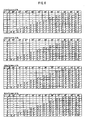
- FIG. 6 shows each of the results based on the interferences.
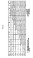
- FIG. 7 arranges the results of the FIG. 6 in one chart.
- a symbol O indicates that contact condition is satisfied while a symbol X indicates that contact condition is not satisfied.
- a numerical value next to each of the symbols denote the angle ⁇ of the first lateral surface portion 15B of the sealing groove 15 relative to a surface that is orthogonal to an axial direction of the cylinder bore 13 (see FIG. 5 ).
- each section of the angle ⁇ is divided into 4 rows.
- tine inclined angle ⁇ of the bottom surface portion 15A of the sealing groove 15 is set to 2 to 8 degrees, not falling under the scope of the present invention while the angle ⁇ defined between the bottom surface portion 15A and the first lateral surface portion 15B is set to 82 to 89 degrees, not falling under the scope of the present invention.
- the interference between the piston 17 and the piston seal 16 it will be preferable to set the interference between the piston 17 and the piston seal 16 while making the piston seal 16 abutted against the bottom surface portion 15A and the first lateral surface portion 15B of the sealing groove 15.
- the inclined angle ⁇ of the bottom surface portion 15A of the sealing groove 15 is set to 2 to 5 degrees. In this condition it will be preferable to set the interference between the piston 17 and the piston seal 16 to 2 to 5%.
- the inclined angle ⁇ of the bottom surface portion 15A of the sealing groove 15 is set to 3 degrees while the angle ⁇ defined between the bottom surface portion 15A and the first lateral surface portion 15B is set to 89 degrees, not falling under the scope of the present invention. In this condition, it will be preferable to set the interference between the piston 17 and the piston seal 16 to be larger than 2%.
- the inclined angle ⁇ of the bottom surface portion 15A of the sealing groove 15 is set to 4 degrees while the angle ⁇ defined between the bottom surface portion 15A and the first lateral surface portion 15B is set to 89 degrees, not falling under the scope of the present invention. In this condition, it will be preferable to set the interference between the piston 17 and the piston seal 16 to be larger than 3%.
- the inclined angle ⁇ of the bottom surface portion 15A of the sealing groove 15 is set to 5 degrees while the angle ⁇ defined between the bottom surface portion 15A and the first lateral surface portion 15B is set to 89 degrees, not falling under the scope of the present invention. In this condition, it will be preferable to set the interference between the piston 17 and the piston seal 16 to be larger than 4%.
- the inclined angle ⁇ of the bottom surface portion 15A of the sealing groove 15 is set to 5 degrees while the angle ⁇ defined between the bottom surface portion 15A and the first lateral surface portion 15B is set to 88 degrees. In this condition, it will be preferable to set the interference between the piston 17 and the piston seal 16 to be larger than 3%.
- the inclined angle ⁇ of the bottom surface portion 15A of the sealing groove 15 is set to 3 to 5 degrees while the angle ⁇ defined between the bottom surface portion 15A and the first lateral surface portion 15B is set to 87 degrees.
- the inclined angle ⁇ of the bottom surface portion 15A of the sealing groove 15 is set to 2 to 8 degrees, not falling under the scope of the present invention while the angle ⁇ defined between the bottom surface portion 15A and the first lateral surface portion 15B is set to 82 to 89 degrees, not falling under the scope of the present invention.
- the angle ⁇ defined between the first lateral surface portion 15B and a surface orthogonal in an axial direction of the cylinder bore 13 is set to 0 to 4 degrees. In this condition, it will be preferable to set the interference between the piston 17 and the piston seal 16 to 5%.
- the sealing groove 15 is composed of: the bottom surface portion 15A that makes the diameter of the sealing groove 15 expanded as moving toward the opening of the cylinder bore 13; the first lateral surface portion 15B that extends from the most marginal portion of the bottom surface portion 15A toward the opening of the sealing groove 15; and the chamfered portion 19 that is provided between the first lateral surface portion 15B and the inner periphery of the cylinder bore 13, the chamfered portion 19 being formed as that the opening of the sealing groove 15 makes expanded in an axial direction of the cylinder bore 13.
- the piston seal 16 and the piston 17 are installed into the cylinder bore 13 while hydraulic pressure based on predetermined empirical pressure is applied.
- the external peripheral surface 16A of the piston seal 16 is completely abutted against the bottom surface portion 15A of the sealing groove 15 while the whole surface of the first lateral surface portion 15B is abutted against the first lateral surface 16B of the piston seal 16.
- the sealing groove 15 is formed as hereinabove discussed whereby it will be certainly possible to remove the clearance between the piston seal 16 and the sealing groove 15 contributing to improvement of a brake operationability.
- the floating-caliper disk brake has been discussed as one example.
- the present invention is not limited thereto, but surely applicable to other types of hydraulic disk brake such as a fixed-caliper disk brake, etc.
Landscapes
- Engineering & Computer Science (AREA)
- General Engineering & Computer Science (AREA)
- Mechanical Engineering (AREA)
- Braking Arrangements (AREA)
Applications Claiming Priority (1)
| Application Number | Priority Date | Filing Date | Title |
|---|---|---|---|
| JP2009020760A JP5282891B2 (ja) | 2009-01-30 | 2009-01-30 | ディスクブレーキ |
Publications (2)
| Publication Number | Publication Date |
|---|---|
| EP2213903A1 EP2213903A1 (en) | 2010-08-04 |
| EP2213903B1 true EP2213903B1 (en) | 2011-11-02 |
Family
ID=42102484
Family Applications (1)
| Application Number | Title | Priority Date | Filing Date |
|---|---|---|---|
| EP10151923A Not-in-force EP2213903B1 (en) | 2009-01-30 | 2010-01-28 | Disk brake |
Country Status (4)
| Country | Link |
|---|---|
| US (1) | US8464849B2 (enExample) |
| EP (1) | EP2213903B1 (enExample) |
| JP (1) | JP5282891B2 (enExample) |
| AT (1) | ATE531965T1 (enExample) |
Families Citing this family (7)
| Publication number | Priority date | Publication date | Assignee | Title |
|---|---|---|---|---|
| WO2013008290A1 (ja) * | 2011-07-08 | 2013-01-17 | 東洋ゴム工業株式会社 | 鉄道車両用空気ばね |
| JP7118144B2 (ja) | 2018-05-29 | 2022-08-15 | 日立Astemo株式会社 | ディスクブレーキ |
| US11085315B2 (en) * | 2019-07-09 | 2021-08-10 | General Electric Company | Turbine engine with a seal |
| CN111981063B (zh) * | 2020-08-18 | 2024-10-15 | 万向钱潮(上海)汽车系统有限公司 | 一种矩形槽结构 |
| CN113090689B (zh) * | 2021-03-31 | 2022-09-23 | 玉环思安安全设备股份有限公司 | 一种改良版制动钳缸体结构 |
| CN113007246B (zh) * | 2021-04-15 | 2025-04-01 | 南方天合底盘系统有限公司 | 一种增力式汽车制动卡钳 |
| DE102022211306A1 (de) * | 2022-10-25 | 2024-04-25 | Hl Mando Corporation | Bremsflüssigkeitsführung zum leiten einer bremsflüssigkeit |
Family Cites Families (9)
| Publication number | Priority date | Publication date | Assignee | Title |
|---|---|---|---|---|
| US4194597A (en) * | 1978-08-01 | 1980-03-25 | Kelsey Hayes Co. | Disc brake anti-rattle means |
| DE4202927C2 (de) * | 1992-02-01 | 2000-11-09 | Continental Teves Ag & Co Ohg | Scheibenbremse mit verbessertem Lüftverhalten |
| DE4331281C1 (de) * | 1993-09-15 | 1995-04-20 | Daimler Benz Ag | Hydraulisch betätigte Vollbelagscheibenbremse |
| US6347689B1 (en) * | 2000-06-30 | 2002-02-19 | Shimano Inc. | Roll back seal for disc brake |
| DE10038892C2 (de) * | 2000-08-09 | 2002-09-26 | Magenwirth Gmbh Co Gustav | Bremszylindergehäuse für eine Scheibenbremse |
| JP4587614B2 (ja) * | 2001-08-01 | 2010-11-24 | 本田技研工業株式会社 | ディスクブレーキ装置 |
| JP4318618B2 (ja) * | 2004-09-30 | 2009-08-26 | 日信工業株式会社 | 液圧式車両用ディスクブレーキ |
| JP4505686B2 (ja) * | 2004-09-30 | 2010-07-21 | 日立オートモティブシステムズ株式会社 | ディスクブレーキ |
| DE102007017512A1 (de) * | 2006-05-03 | 2007-12-13 | Continental Teves Ag & Co. Ohg | Bremssattel |
-
2009
- 2009-01-30 JP JP2009020760A patent/JP5282891B2/ja not_active Expired - Fee Related
-
2010
- 2010-01-28 AT AT10151923T patent/ATE531965T1/de active
- 2010-01-28 US US12/656,390 patent/US8464849B2/en not_active Expired - Fee Related
- 2010-01-28 EP EP10151923A patent/EP2213903B1/en not_active Not-in-force
Also Published As
| Publication number | Publication date |
|---|---|
| JP2010175041A (ja) | 2010-08-12 |
| EP2213903A1 (en) | 2010-08-04 |
| ATE531965T1 (de) | 2011-11-15 |
| JP5282891B2 (ja) | 2013-09-04 |
| US8464849B2 (en) | 2013-06-18 |
| US20100194056A1 (en) | 2010-08-05 |
Similar Documents
| Publication | Publication Date | Title |
|---|---|---|
| EP2213903B1 (en) | Disk brake | |
| CN104271978B (zh) | 带有复位装置的盘式制动器和制动衬片 | |
| US4121845A (en) | Boot for slidably guided member | |
| US11965567B2 (en) | Disc brake | |
| US6257379B1 (en) | Disk brake | |
| EP2370707B1 (en) | Device for retracting a piston for a brake caliper | |
| US20130025983A1 (en) | Disc Brake Having Reduced Residual Grinding Torque | |
| EP2372183A1 (en) | Disk brake | |
| US6983830B2 (en) | Disc brake | |
| US20040007431A1 (en) | Wheel cylinder | |
| JP5370684B2 (ja) | ディスクブレーキ装置 | |
| US20250043837A1 (en) | Motor vehicle disc brake with bellows-type sleeve for sealing a bolt guide device and bellows-type sleeve | |
| KR20160076256A (ko) | 자동차용 캘리퍼 브레이크 | |
| KR20200034103A (ko) | 전자식 디스크 브레이크 | |
| KR102793210B1 (ko) | 캘리퍼 브레이크용 브라켓 및 이를 구비한 캘리퍼 브레이크 | |
| TW200422538A (en) | A wheel cylinder for actuating a vehicle brake and a method of manufacturing same | |
| JP2019056450A (ja) | 車両用ディスクブレーキ | |
| JPS5912451Y2 (ja) | 油圧シリンダ | |
| JP3976047B2 (ja) | ディスクブレーキ装置 | |
| US20120125723A1 (en) | Disk brake assembly | |
| KR20070060520A (ko) | 디스크브레이크 | |
| KR100710475B1 (ko) | 디스크 브레이크 | |
| JP4978442B2 (ja) | ディスクブレーキ | |
| JPH1037987A (ja) | ディスクブレーキ装置 | |
| KR20090088650A (ko) | 디스크 브레이크 |
Legal Events
| Date | Code | Title | Description |
|---|---|---|---|
| PUAI | Public reference made under article 153(3) epc to a published international application that has entered the european phase |
Free format text: ORIGINAL CODE: 0009012 |
|
| AK | Designated contracting states |
Kind code of ref document: A1 Designated state(s): AT BE BG CH CY CZ DE DK EE ES FI FR GB GR HR HU IE IS IT LI LT LU LV MC MK MT NL NO PL PT RO SE SI SK SM TR |
|
| AX | Request for extension of the european patent |
Extension state: AL BA RS |
|
| 17P | Request for examination filed |
Effective date: 20110202 |
|
| GRAP | Despatch of communication of intention to grant a patent |
Free format text: ORIGINAL CODE: EPIDOSNIGR1 |
|
| RIC1 | Information provided on ipc code assigned before grant |
Ipc: F16J 15/32 20060101ALI20110411BHEP Ipc: F16D 65/14 20060101AFI20110411BHEP Ipc: F16D 65/00 20060101ALI20110411BHEP |
|
| RIN1 | Information on inventor provided before grant (corrected) |
Inventor name: KONO, KIMIYASU Inventor name: NANRI, KEISUKE |
|
| GRAS | Grant fee paid |
Free format text: ORIGINAL CODE: EPIDOSNIGR3 |
|
| GRAA | (expected) grant |
Free format text: ORIGINAL CODE: 0009210 |
|
| AK | Designated contracting states |
Kind code of ref document: B1 Designated state(s): AT BE BG CH CY CZ DE DK EE ES FI FR GB GR HR HU IE IS IT LI LT LU LV MC MK MT NL NO PL PT RO SE SI SK SM TR |
|
| REG | Reference to a national code |
Ref country code: GB Ref legal event code: FG4D |
|
| REG | Reference to a national code |
Ref country code: CH Ref legal event code: EP |
|
| REG | Reference to a national code |
Ref country code: IE Ref legal event code: FG4D |
|
| REG | Reference to a national code |
Ref country code: DE Ref legal event code: R096 Ref document number: 602010000322 Country of ref document: DE Effective date: 20120126 |
|
| REG | Reference to a national code |
Ref country code: NL Ref legal event code: VDEP Effective date: 20111102 |
|
| LTIE | Lt: invalidation of european patent or patent extension |
Effective date: 20111102 |
|
| PG25 | Lapsed in a contracting state [announced via postgrant information from national office to epo] |
Ref country code: LT Free format text: LAPSE BECAUSE OF FAILURE TO SUBMIT A TRANSLATION OF THE DESCRIPTION OR TO PAY THE FEE WITHIN THE PRESCRIBED TIME-LIMIT Effective date: 20111102 Ref country code: IS Free format text: LAPSE BECAUSE OF FAILURE TO SUBMIT A TRANSLATION OF THE DESCRIPTION OR TO PAY THE FEE WITHIN THE PRESCRIBED TIME-LIMIT Effective date: 20120302 Ref country code: NO Free format text: LAPSE BECAUSE OF FAILURE TO SUBMIT A TRANSLATION OF THE DESCRIPTION OR TO PAY THE FEE WITHIN THE PRESCRIBED TIME-LIMIT Effective date: 20120202 |
|
| PG25 | Lapsed in a contracting state [announced via postgrant information from national office to epo] |
Ref country code: BE Free format text: LAPSE BECAUSE OF FAILURE TO SUBMIT A TRANSLATION OF THE DESCRIPTION OR TO PAY THE FEE WITHIN THE PRESCRIBED TIME-LIMIT Effective date: 20111102 Ref country code: PT Free format text: LAPSE BECAUSE OF FAILURE TO SUBMIT A TRANSLATION OF THE DESCRIPTION OR TO PAY THE FEE WITHIN THE PRESCRIBED TIME-LIMIT Effective date: 20120302 Ref country code: SI Free format text: LAPSE BECAUSE OF FAILURE TO SUBMIT A TRANSLATION OF THE DESCRIPTION OR TO PAY THE FEE WITHIN THE PRESCRIBED TIME-LIMIT Effective date: 20111102 Ref country code: PL Free format text: LAPSE BECAUSE OF FAILURE TO SUBMIT A TRANSLATION OF THE DESCRIPTION OR TO PAY THE FEE WITHIN THE PRESCRIBED TIME-LIMIT Effective date: 20111102 Ref country code: NL Free format text: LAPSE BECAUSE OF FAILURE TO SUBMIT A TRANSLATION OF THE DESCRIPTION OR TO PAY THE FEE WITHIN THE PRESCRIBED TIME-LIMIT Effective date: 20111102 Ref country code: GR Free format text: LAPSE BECAUSE OF FAILURE TO SUBMIT A TRANSLATION OF THE DESCRIPTION OR TO PAY THE FEE WITHIN THE PRESCRIBED TIME-LIMIT Effective date: 20120203 Ref country code: SE Free format text: LAPSE BECAUSE OF FAILURE TO SUBMIT A TRANSLATION OF THE DESCRIPTION OR TO PAY THE FEE WITHIN THE PRESCRIBED TIME-LIMIT Effective date: 20111102 Ref country code: HR Free format text: LAPSE BECAUSE OF FAILURE TO SUBMIT A TRANSLATION OF THE DESCRIPTION OR TO PAY THE FEE WITHIN THE PRESCRIBED TIME-LIMIT Effective date: 20111102 Ref country code: LV Free format text: LAPSE BECAUSE OF FAILURE TO SUBMIT A TRANSLATION OF THE DESCRIPTION OR TO PAY THE FEE WITHIN THE PRESCRIBED TIME-LIMIT Effective date: 20111102 |
|
| PG25 | Lapsed in a contracting state [announced via postgrant information from national office to epo] |
Ref country code: CY Free format text: LAPSE BECAUSE OF FAILURE TO SUBMIT A TRANSLATION OF THE DESCRIPTION OR TO PAY THE FEE WITHIN THE PRESCRIBED TIME-LIMIT Effective date: 20111102 |
|
| PG25 | Lapsed in a contracting state [announced via postgrant information from national office to epo] |
Ref country code: EE Free format text: LAPSE BECAUSE OF FAILURE TO SUBMIT A TRANSLATION OF THE DESCRIPTION OR TO PAY THE FEE WITHIN THE PRESCRIBED TIME-LIMIT Effective date: 20111102 Ref country code: BG Free format text: LAPSE BECAUSE OF FAILURE TO SUBMIT A TRANSLATION OF THE DESCRIPTION OR TO PAY THE FEE WITHIN THE PRESCRIBED TIME-LIMIT Effective date: 20120202 Ref country code: DK Free format text: LAPSE BECAUSE OF FAILURE TO SUBMIT A TRANSLATION OF THE DESCRIPTION OR TO PAY THE FEE WITHIN THE PRESCRIBED TIME-LIMIT Effective date: 20111102 Ref country code: CZ Free format text: LAPSE BECAUSE OF FAILURE TO SUBMIT A TRANSLATION OF THE DESCRIPTION OR TO PAY THE FEE WITHIN THE PRESCRIBED TIME-LIMIT Effective date: 20111102 Ref country code: SK Free format text: LAPSE BECAUSE OF FAILURE TO SUBMIT A TRANSLATION OF THE DESCRIPTION OR TO PAY THE FEE WITHIN THE PRESCRIBED TIME-LIMIT Effective date: 20111102 |
|
| PG25 | Lapsed in a contracting state [announced via postgrant information from national office to epo] |
Ref country code: RO Free format text: LAPSE BECAUSE OF FAILURE TO SUBMIT A TRANSLATION OF THE DESCRIPTION OR TO PAY THE FEE WITHIN THE PRESCRIBED TIME-LIMIT Effective date: 20111102 Ref country code: MC Free format text: LAPSE BECAUSE OF NON-PAYMENT OF DUE FEES Effective date: 20120131 |
|
| PLBE | No opposition filed within time limit |
Free format text: ORIGINAL CODE: 0009261 |
|
| STAA | Information on the status of an ep patent application or granted ep patent |
Free format text: STATUS: NO OPPOSITION FILED WITHIN TIME LIMIT |
|
| REG | Reference to a national code |
Ref country code: AT Ref legal event code: MK05 Ref document number: 531965 Country of ref document: AT Kind code of ref document: T Effective date: 20111102 |
|
| 26N | No opposition filed |
Effective date: 20120803 |
|
| REG | Reference to a national code |
Ref country code: FR Ref legal event code: ST Effective date: 20120928 |
|
| REG | Reference to a national code |
Ref country code: IE Ref legal event code: MM4A |
|
| REG | Reference to a national code |
Ref country code: DE Ref legal event code: R097 Ref document number: 602010000322 Country of ref document: DE Effective date: 20120803 |
|
| PG25 | Lapsed in a contracting state [announced via postgrant information from national office to epo] |
Ref country code: FR Free format text: LAPSE BECAUSE OF NON-PAYMENT OF DUE FEES Effective date: 20120131 |
|
| PG25 | Lapsed in a contracting state [announced via postgrant information from national office to epo] |
Ref country code: IE Free format text: LAPSE BECAUSE OF NON-PAYMENT OF DUE FEES Effective date: 20120128 Ref country code: AT Free format text: LAPSE BECAUSE OF FAILURE TO SUBMIT A TRANSLATION OF THE DESCRIPTION OR TO PAY THE FEE WITHIN THE PRESCRIBED TIME-LIMIT Effective date: 20111102 |
|
| PG25 | Lapsed in a contracting state [announced via postgrant information from national office to epo] |
Ref country code: MK Free format text: LAPSE BECAUSE OF FAILURE TO SUBMIT A TRANSLATION OF THE DESCRIPTION OR TO PAY THE FEE WITHIN THE PRESCRIBED TIME-LIMIT Effective date: 20111102 |
|
| PG25 | Lapsed in a contracting state [announced via postgrant information from national office to epo] |
Ref country code: ES Free format text: LAPSE BECAUSE OF FAILURE TO SUBMIT A TRANSLATION OF THE DESCRIPTION OR TO PAY THE FEE WITHIN THE PRESCRIBED TIME-LIMIT Effective date: 20120213 |
|
| PG25 | Lapsed in a contracting state [announced via postgrant information from national office to epo] |
Ref country code: FI Free format text: LAPSE BECAUSE OF FAILURE TO SUBMIT A TRANSLATION OF THE DESCRIPTION OR TO PAY THE FEE WITHIN THE PRESCRIBED TIME-LIMIT Effective date: 20111102 |
|
| PG25 | Lapsed in a contracting state [announced via postgrant information from national office to epo] |
Ref country code: MT Free format text: LAPSE BECAUSE OF FAILURE TO SUBMIT A TRANSLATION OF THE DESCRIPTION OR TO PAY THE FEE WITHIN THE PRESCRIBED TIME-LIMIT Effective date: 20111102 |
|
| PG25 | Lapsed in a contracting state [announced via postgrant information from national office to epo] |
Ref country code: TR Free format text: LAPSE BECAUSE OF FAILURE TO SUBMIT A TRANSLATION OF THE DESCRIPTION OR TO PAY THE FEE WITHIN THE PRESCRIBED TIME-LIMIT Effective date: 20111102 |
|
| PG25 | Lapsed in a contracting state [announced via postgrant information from national office to epo] |
Ref country code: SM Free format text: LAPSE BECAUSE OF FAILURE TO SUBMIT A TRANSLATION OF THE DESCRIPTION OR TO PAY THE FEE WITHIN THE PRESCRIBED TIME-LIMIT Effective date: 20111102 Ref country code: LU Free format text: LAPSE BECAUSE OF NON-PAYMENT OF DUE FEES Effective date: 20120128 |
|
| PG25 | Lapsed in a contracting state [announced via postgrant information from national office to epo] |
Ref country code: HU Free format text: LAPSE BECAUSE OF FAILURE TO SUBMIT A TRANSLATION OF THE DESCRIPTION OR TO PAY THE FEE WITHIN THE PRESCRIBED TIME-LIMIT Effective date: 20100128 |
|
| REG | Reference to a national code |
Ref country code: CH Ref legal event code: PL |
|
| GBPC | Gb: european patent ceased through non-payment of renewal fee |
Effective date: 20140128 |
|
| PG25 | Lapsed in a contracting state [announced via postgrant information from national office to epo] |
Ref country code: LI Free format text: LAPSE BECAUSE OF NON-PAYMENT OF DUE FEES Effective date: 20140131 Ref country code: CH Free format text: LAPSE BECAUSE OF NON-PAYMENT OF DUE FEES Effective date: 20140131 |
|
| PG25 | Lapsed in a contracting state [announced via postgrant information from national office to epo] |
Ref country code: GB Free format text: LAPSE BECAUSE OF NON-PAYMENT OF DUE FEES Effective date: 20140128 |
|
| PGFP | Annual fee paid to national office [announced via postgrant information from national office to epo] |
Ref country code: IT Payment date: 20201211 Year of fee payment: 12 |
|
| PGFP | Annual fee paid to national office [announced via postgrant information from national office to epo] |
Ref country code: DE Payment date: 20210112 Year of fee payment: 12 |
|
| REG | Reference to a national code |
Ref country code: DE Ref legal event code: R119 Ref document number: 602010000322 Country of ref document: DE |
|
| PG25 | Lapsed in a contracting state [announced via postgrant information from national office to epo] |
Ref country code: DE Free format text: LAPSE BECAUSE OF NON-PAYMENT OF DUE FEES Effective date: 20220802 |
|
| PG25 | Lapsed in a contracting state [announced via postgrant information from national office to epo] |
Ref country code: IT Free format text: LAPSE BECAUSE OF NON-PAYMENT OF DUE FEES Effective date: 20220128 |