EP2213802A1 - Zuführvorrichtung zum Zuführen von Beton und Gas in den Bohrstrang eines Bohrgerätes beim Erstellen eines betonierten Bohrlochs und Verfahren zum Erstellen eines betonierten Bohrlochs - Google Patents
Zuführvorrichtung zum Zuführen von Beton und Gas in den Bohrstrang eines Bohrgerätes beim Erstellen eines betonierten Bohrlochs und Verfahren zum Erstellen eines betonierten Bohrlochs Download PDFInfo
- Publication number
- EP2213802A1 EP2213802A1 EP09001400A EP09001400A EP2213802A1 EP 2213802 A1 EP2213802 A1 EP 2213802A1 EP 09001400 A EP09001400 A EP 09001400A EP 09001400 A EP09001400 A EP 09001400A EP 2213802 A1 EP2213802 A1 EP 2213802A1
- Authority
- EP
- European Patent Office
- Prior art keywords
- concrete
- valve
- gas
- connection
- drill string
- Prior art date
- Legal status (The legal status is an assumption and is not a legal conclusion. Google has not performed a legal analysis and makes no representation as to the accuracy of the status listed.)
- Granted
Links
Images




Classifications
-
- E—FIXED CONSTRUCTIONS
- E02—HYDRAULIC ENGINEERING; FOUNDATIONS; SOIL SHIFTING
- E02D—FOUNDATIONS; EXCAVATIONS; EMBANKMENTS; UNDERGROUND OR UNDERWATER STRUCTURES
- E02D5/00—Bulkheads, piles, or other structural elements specially adapted to foundation engineering
- E02D5/22—Piles
- E02D5/34—Concrete or concrete-like piles cast in position ; Apparatus for making same
- E02D5/38—Concrete or concrete-like piles cast in position ; Apparatus for making same making by use of mould-pipes or other moulds
-
- E—FIXED CONSTRUCTIONS
- E02—HYDRAULIC ENGINEERING; FOUNDATIONS; SOIL SHIFTING
- E02D—FOUNDATIONS; EXCAVATIONS; EMBANKMENTS; UNDERGROUND OR UNDERWATER STRUCTURES
- E02D5/00—Bulkheads, piles, or other structural elements specially adapted to foundation engineering
- E02D5/66—Mould-pipes or other moulds
- E02D5/665—Mould-pipes or other moulds for making piles
Definitions
- the invention relates to a delivery device for supplying concrete and gas into the drill string of a drill when creating a concrete well according to the preamble of claim 1.
- a delivery device is formed with at least one drill string connection for connection to the drill string, a concrete connector for connection to a concrete conveyor a gas connection for connection to a compressed gas source, a line arrangement, via which the concrete connection and the gas connection are connected to the Bohrstrangan gleich, a concrete valve which is provided in the line arrangement, and with which a connection between the concrete connection and the Bohrstrangan gleich can be shut off, and a gas valve, which is provided in the line arrangement, and with which a connection between the gas connection and the drill string connection can be shut off.
- the invention further relates to a method for producing a concrete borehole according to the preamble of claim 15.
- a drill string is lowered into the ground by means of a drill drive, and the drill string is subsequently pulled and the drill hole released in the process is filled with concrete via the drill string. wherein upon retraction of the drill string, the drill string is placed under gas pressure by supplying gas into the drill string.
- the cuttings to be conveyed are circulated by air during the introduction of air, they can already dry during delivery, and thus adhere less strongly to the helix of the endless worm, which results in improved cuttings ejection.
- the pre-dried cuttings usually do not pollute the construction site as much as wet cuttings.
- drills with a feeder for feeding concrete and gas into the drill string of the endless screw are known.
- the supply device is provided with a concrete connection and a gas connection for connection to the corresponding conveyors. It also has a valve arrangement which allows the drill driver to initiate gas or concrete into the drill string in the different drilling phases.
- the object of the invention is to provide a feeding device for supplying concrete and gas in the drill string of a drill when creating a concrete borehole and a method for creating a concrete borehole, with which in a particularly simple and reliable way concreted boreholes, ie concrete piles of particular high quality can be produced.
- the feeding device is characterized in that the concrete valve has a mechanical actuating element for actuating the gas valve, wherein the mechanical actuating element is arranged such that the gas valve is shut off when the concrete valve is opened.
- the invention has recognized that the gas supply into the drill string, which is advantageous and desirable during the drilling of the drill string for the reasons mentioned above, however, may be disadvantageous in the subsequent concreting of the borehole.
- the gas supply should be reliably interrupted during the concreting process.
- the invention comes in and provides a valve assembly in which the concrete valve and the gas valve interact mechanically to automatically shut off the gas valve and thus inhibit gas supply in the drill string when the concrete valve is opened and concrete into the drill string can flow.
- the concrete valve has a mechanical actuator which is arranged and configured to shut off the gas valve when the concrete valve is opened.
- the gas valve is automatically actuated according to the position of the concrete valve according to the invention, so that incorrect operation during concreting can be avoided and thus a high quality of the created bored piles is ensured.
- a drill with a feeding device according to the invention is particularly easy to use, since the driver only has to open the concrete valve for concreting, whereby the gas valve is closed at the same time.
- the gas which is fed into the drill string is expediently air.
- the drill string is suitably the core tube of a drilling screw, in particular an endless screw.
- the concrete conveyor may be a concrete pump and the compressed gas source may be a gas compressor.
- At least one of the connections expediently has a connecting flange and / or a pipe socket for connection to delivery lines or to the drill string.
- the feeder is introduced at the upper end of the drill string in the concrete supply line.
- the mechanical actuating element is arranged such that the gas valve opens when the concrete valve is shut off. In this way it can be ensured that an overpressure in the core tube is automatically produced when the driver closes the core tube formed by the drill string for concrete during drilling, since the air supply is opened simultaneously when the concrete valve is closed. Premature and undesirable penetration of concrete during the drilling process can thus be prevented.
- a particularly preferred embodiment of the invention is that the concrete valve is a slide valve with a slide element. It has been shown that with a slide valve, ie a valve in which the shut-off is a slide element, despite the setting properties of concrete reliable control of the flow of concrete is possible with low production costs. With regard to the design effort is particularly advantageous that the slide element is designed as a slide plate. In principle, however, the slide element can also be configured wedge-shaped, for example. Also multiple plate arrangements are possible. If the concrete valve is designed as a slide valve, the supply device can also be referred to as a concrete change slide, since the valves of the feed device are designed so that they alternately allow passage of gas or concrete to Bohrstrangan gleich.
- the mechanical actuating element is a plunger, which is preferably arranged on the concrete valve, in particular on the shut-off of the concrete valve.
- a plunger can transmit a linear movement of the shut-off of the concrete valve to the shut-off of the gas valve in a particularly simple manner, so that the gas valve is automatically switched over the plunger when the concrete valve is switched.
- the mechanical actuator is attached to the concrete valve, in particular on the shut-off of the concrete valve.
- the actuating element can also be fastened to the gas valve, in particular to the shut-off element of the gas valve.
- the actuating element is movable relative to the shut-off bodies of both valves, and only temporarily applied to the switching of the gas valve to the valves, is conceivable.
- the mechanical actuating element is arranged on the slide element, in particular on a narrow side of the slide element.
- the actuating element is arranged on a concrete valve side narrow side of the slide element, which preferably faces the gas valve.
- the actuating element may lie in the plane of the slider element and / or the plane in which the slider element moves when opening and closing.
- For receiving the actuating element can then be provided a hole in the alignment of the slide element, which is particularly easy to manufacture.
- the gas valve is a seat valve.
- a seat valve may, in particular, be understood to mean a valve in which, for example, a conical shut-off body strikes a ring-like seat in the valve housing when closing.
- the poppet valve is a poppet valve.
- a piston valve or a slide valve may be provided as a gas valve instead of a poppet valve.
- a further preferred embodiment is provided in that a clamping device is provided which holds the gas valve in a closed state.
- the clamping device for example, a spring, in particular a coil spring having, which presses the shut-off of the gas valve in the valve seat.
- the gas which flows through the gas connection in the gas valve, can serve as a tensioning device, and hold the gas valve in the locked state.
- the shut-off of the gas valve is mushroom-shaped, whereby, inter alia, a particularly suitable attack surface for the gas acting as a tensioning device is given.
- the shut-off of the gas valve has a contact surface for the mechanical actuator.
- the mechanical actuator acts directly on the shut-off, so that a structurally particularly simple arrangement is given.
- the contact surface for the mechanical actuating element is arranged in the flow channel of the gas valve and / or faces an outlet channel of the gas valve.
- the mechanical actuator in the outlet of the gas valve can be arranged, which further reduces the design effort, because in this case no additional holes for the actuator are required except the outlet channel.
- the actuating element is only temporarily applied to the contact surface, in particular for opening the gas valve.
- the mechanical actuating element is arranged at least when the gas valve is open in the outlet channel of the gas valve.
- the mechanical actuating element can be arranged coaxially with the outlet channel. This allows a reliable gas flow and avoids unwanted friction of the actuating element on the outlet channel.
- the outlet channel of the gas valve is expediently located in the plane in which the sliding element moves when opening and closing.
- a gas channel is provided for supplying the gas to the drill string connection.
- the slide element fulfills a dual function and serves on the one hand to shut off the concrete flow and on the other hand to pass the compressed gas. This makes it possible to produce a particularly effective gas flow profile in a particularly simple and compact construction of the feeder.
- the gas channel has at least one gas inlet opening, which is preferably arranged on a narrow side of the slide element.
- the gas inlet opening can be arranged on the concrete valve-side narrow side of the slide element, which faces the gas valve.
- the gas channel has a gas outlet opening, which is arranged on a flat side of the slide element.
- a flat side may, in particular, be understood as meaning a side of the slide element which is arranged approximately perpendicularly to the line course to be shut off.
- the flat side can also be referred to as the sealing side of the slider element.
- the mechanical actuating element is arranged in the region of the at least gas inlet opening of the gas channel on the slide element. In this way, the sealing effort can be reduced because the sealing of the gas inlet opening can simultaneously serve to seal the nearby arranged actuator.
- the mechanical actuating element is surrounded by gas inlet openings. According to this embodiment, the actuating element is thus arranged between at least two gas inlet openings, which can be arranged for example on a ring around the actuating element.
- the slide element has a preferably circular passage opening for the connection between the concrete connection and the drill string connection.
- a perforated slider element is provided, which releases the passage opening during a stroke movement. This embodiment can allow a particularly good sealing effect.
- a particularly compact design which also allows easy retrofitting of drilling equipment, according to a preferred embodiment be given by the fact that the concrete connection and the Bohrstrangan gleich on opposite Side of a valve housing of the concrete valve are arranged.
- the concrete connection and the drill string connection can be arranged coaxially with one another.
- the gas valve is expediently provided radially to the concrete connection and / or the Bohrstrangan gleich, that is, the longitudinal axis of the gas valve is preferably perpendicular to the longitudinal axis of the line section, which can be shut off with the slide element, and, if present, perpendicular to the longitudinal axis of the passage opening in the slide element.
- the gas valve is arranged in the displacement plane of the slide element.
- valve drive is provided for actuating the concrete valve. This allows to operate the concrete valve remotely. Since the gas valve according to the invention is coupled to the concrete valve, according to the invention basically only a single valve drive is required, which reduces the manufacturing costs.
- the valve drive may be a hydraulic drive. The hydraulic sources already provided on the drill can then also be used to actuate the concrete valve.
- valve drive has two hydraulic cylinders, which are arranged on both sides of the slide element.
- two hydraulic cylinders are connected via a yoke, on which the slide element is arranged.
- the invention also relates to a drilling rig with a carrier vehicle, on which a drill drive for driving a drill string is arranged.
- An inventive drill is characterized in that a feed device according to the invention for supplying concrete and gas is provided in the drill string.
- the method according to the invention for producing a concreted borehole is characterized in that a feed device according to the invention is provided on the drilling device and that the supply of gas into the drill string is interrupted by means of the feed device when concrete is introduced into the drill string.
- FIGS. 1 to 3 An embodiment of a feeding device 1 according to the invention is in the FIGS. 1 to 3 shown with the concrete valve 60 open.
- the feeding device 1 has a concrete valve 60 designed as a slide valve with a box-shaped valve housing 63.
- Bohrstrangan gleich 3 On a front flat side of the valve housing 63 designed as a flange element Bohrstrangan gleich 3 is provided, via which a line connection with a purely in Fig. 6 schematically illustrated drill string 12 of an endless screw drill can be produced.
- On the opposite, rear flat side of the valve housing 63 designed as a pipe socket concrete connection 6 is provided, via which a line connection with a concrete pump can be produced ( Fig. 2 ).
- the concrete connection 6 and the drill string connection 3 are arranged at least approximately coaxially on opposite sides of the valve housing 63. For a particularly reliable Connection with a concrete hose are provided on the outside of the pipe socket of the concrete connection 6 retaining rings.
- a slot 67 ( Fig. 3 ) is formed, in which a valve plate designed as a slide member 61 is arranged adjustable in the vertical direction.
- This slide member 61 forms the shut-off of the concrete valve 60.
- a circular passage opening 62 is provided in the plate-shaped slide member 61.
- the passage opening 62 is arranged in an upper, valve inner side region of the slide element 61.
- the slide member 61 is moved out of the valve housing 63 down so that the passage opening 62 in the slide member 61 at least partially aligned with the Bohrstrangan gleich 3 and the concrete port 6, and therefore a passage of concrete from the concrete port 6 in the Bohrstrangan gleich 3 and thus in the drill string 12 allows.
- a hydraulic valve drive with two hydraulic cylinders 31 and 31 'is provided.
- the two hydraulic cylinders extend on both sides of the valve housing 63 parallel to each other along the valve housing 63 from top to bottom.
- the hydraulic cylinders 31, 31 ' are fastened on the one hand in an upper region of the valve housing 63 on the valve housing 63, and on the other hand on a common yoke 33 which extends below the valve housing 63, and on which the slide member 61 attached, screwed in the illustrated embodiment.
- the yoke 33 consists of two yoke elements 34, 34 ', between which the slide element 61 is arranged ( Fig. 1 ).
- the two yoke elements 34, 34 ' extend parallel to each other in the horizontal direction and are both respectively attached to the piston rods of both hydraulic cylinders 31, 31'.
- FIGS. 1 to 3 show the extended state with open concrete valve 60
- FIGS. 4 and 5 show the retracted state of the slide element 61.
- the through-hole 62 is laterally offset from the terminals 3 and 6, and a passage of concrete between the terminals 3 and 6 becomes from the flat sides 65, 65 'of the slider member 61 is between the terminals 3 and 6, locked.
- a gas connection 7 designed as a pipe socket is provided on the top of the supply device 1 for connection to a compressed air source.
- the gas connection 7 is connected via a pipe bend 20 with a gas valve 70, which is arranged on the upper side of the valve housing 63 of the concrete valve 60.
- the gas valve 70 is designed as a seat valve and has a vertical line profile which is perpendicular to the line section 68 (FIG. Fig. 5 ), which can be shut off with the slide element, ie at right angles to the connecting line between the drill pipe connection 3 and the concrete connection 6. Due to the pipe bend 20, which has a line curvature of 90 ° result, despite the vertical line arrangement on the gas valve 70 at the gas port 7, a horizontal line course given, allowing a particularly simple hose connection to the gas port 7.
- the gas valve 70 has a mushroom-shaped shut-off body 71, which is arranged longitudinally displaceably in a valve housing 73 of the gas valve 70 ( Figures 3 and 4 ).
- a mechanical actuating element 80 is provided on the slide element 61 of the concrete valve 60.
- the actuating element 80 is designed as a cylindrical plunger and protrudes from a rear, valve inner side narrow side 69 of the slide member 61 which extends horizontally and the gas valve 70 faces.
- the contact surface 78 is provided on the front side on the widened side of the mushroom-shaped shut-off body 71.
- the actuating element 80 penetrates into the outlet channel 79 of the gas valve 70 when the slide element 61 is retracted and acts on the contact surface 78 and the shut-off body 71 through the outlet channel 79.
- the outlet channel 79 of the gas valve 70 leads into the slot 67 in the interior of the valve housing 63 of the concrete valve 60.
- a gas passage 50 is provided in the slide member 61 of the concrete valve.
- the gas channel 50 begins on the concrete valve inside narrow side 69 and there has gas inlet openings 51, 51 ', which surround the actuator 80, and which come with retracted slide member 61 in front of the outlet channel 79 of the gas valve 70, so that from the outlet channel 79 of the gas valve 70 leaking gas via the gas inlet openings 51, 51 'enters the gas channel 50.
- the gas channel 50 has a gas outlet opening 52 which is arranged in that flat side 65 of the slide element 61 which faces the drill pipe connection 3 ( Fig. 5 ).
- the gas outlet opening 52 is provided offset down to the passage opening 62 and arranged so that it coaxially aligned with retracted slide element 61 with the Bohrstrangan gleich 3 ( Fig. 5 ).
- shut-off body 71 can now lower to the valve seat of the valve housing 73 of the gas valve 70 and lock the gas valve 70 for a gas passage (in Fig. 3 the shut-off 71 is still shown in the open state, just before the shut-off 71 closes).
- the closing of the shut-off body 71 may, for example due to of gas pressure at the gas connection 7 take place. However, it can also be provided as a tensioning device, for example a helical spring, which surrounds the shaft of the mushroom-shaped shut-off body 71.
- the actuator 80 no longer acts on the shut-off body 71 of the gas valve 70 when the slide element 61 is extended, it can close, so that a gas supply between the gas connection 7 and the drill pipe connection 3 is interrupted.
- a passage between the concrete connection 6 and the drill pipe connection 3 is possible, since the passage opening 62 comes to lie in this position between the two connections 6 and 3. This ensures that when introducing concrete into the drill string 12, the gas supply via the gas connection 7 is blocked.
- the gas channel 50 is formed in three parts. It has a first portion 54 which extends vertically in the direction of movement of the slide member 61 at the passage opening 62. This is followed at right angles to a second section 54 ', which extends perpendicular to the direction of movement horizontally along the flat sides 65, 65' of the slide element 61. This is adjoined at right angles by a third section 54 ", which runs horizontally, perpendicular to the direction of movement of the slide element 61 and perpendicular to the flat sides 65, 65 ', and on which the gas outlet opening 52 is arranged ( Fig. 5 ).
- the sections 54, 54 'and 54 are each formed as bores.
- the passage opening 62 releases or blocks a passage between the concrete connection 6 and the drill pipe connection 3.
- the gas valve 70 is thereby blocked or released via the actuating element 80 for a gas connection between the gas connection 7 and the drill pipe connection 3.
- the actuating element 80 is arranged on the slide element 61, it is ensured that the concrete valve 60 and the Gas valve 70 are synchronously switched in opposite directions, so that either the concrete port 6 or the gas port 7 is in communication with the drill string connection 3, but never both ports 6, 7 simultaneously.
- Fig. 6 shows the arrangement of the feeding device 1 of FIGS. 1 to 5 on the mast head of a carrier vehicle 10, of which only the mast is shown for the sake of clarity.
- a drill drive 11 is provided for rotationally driving the drill string 12 only schematically shown.
- the feeding device 1 is arranged above the drill drive 11.
- the still standing drill pipe connection 3 of the stationary feed device 1 is connected to the rotating drill string 12 via a rotary feedthrough 15 in line connection, which is arranged above the drill drive 11.
- a concrete hose 16 is shown, which is flanged to produce a line connection with a concrete pump on the concrete connection 6.
Landscapes
- Engineering & Computer Science (AREA)
- Structural Engineering (AREA)
- Life Sciences & Earth Sciences (AREA)
- General Life Sciences & Earth Sciences (AREA)
- Mining & Mineral Resources (AREA)
- Paleontology (AREA)
- Civil Engineering (AREA)
- General Engineering & Computer Science (AREA)
- Fluid-Driven Valves (AREA)
- Filling Or Discharging Of Gas Storage Vessels (AREA)
Abstract
Description
- Die Erfindung betrifft eine Zuführvorrichtung zum Zuführen von Beton und Gas in den Bohrstrang eines Bohrgerätes beim Erstellen eines betonierten Bohrlochs gemäß dem Oberbegriff des Anspruchs 1. Eine solche Zuführvorrichtung ist ausgebildet mit zumindest einem Bohrstranganschluss zum Anschließen an den Bohrstrang, einem Betonanschluss zum Anschließen an eine Betonfördereinrichtung, einem Gasanschluss zum Anschließen an eine Druckgasquelle, einer Leitungsanordnung, über welche der Betonanschluss und der Gasanschluss mit dem Bohrstranganschluss verbunden sind, einem Betonventil, welches in der Leitungsanordnung vorgesehen ist, und mit welchem eine Verbindung zwischen dem Betonanschluss und dem Bohrstranganschluss absperrbar ist, und einem Gasventil, welches in der Leitungsanordnung vorgesehen ist, und mit welchem eine Verbindung zwischen dem Gasanschluss und dem Bohrstranganschluss absperrbar ist.
- Die Erfindung betrifft ferner ein Verfahren zum Erstellen eines betonierten Bohrlochs gemäß dem Oberbegriff des Anspruchs 15. Bei einem solchen Verfahren wird mittels eines Bohrantriebes ein Bohrstrang in den Boden eingefahren, und der Bohrstrang anschließend gezogen und das hierbei freiwerdende Bohrloch über den Bohrstrang mit Beton verfüllt, wobei beim Einfahren des Bohrstrangs der Bohrstrang durch Zufuhr von Gas in den Bohrstrang unter Gasüberdruck gesetzt wird.
- Zum Herstellen von Betonpfählen ist es bekannt, mit einer Endlosschnecke ein Bohrloch zu erstellen und den Pfahl beim Ziehen der Endlosschnecke über das Seelenrohr der Endlosschnecke zu betonieren. Da die untere, bodenseitige Auslassöffnung für den Beton im Seelenrohr häufig nicht verschließbar ist, kann vorgesehen sein, das Innere des Seelenrohrs beim Abbohren unter Luftüberdruck (ca. 5-15 bar) zu setzen. Dies hat den Vorteil, dass kein Grundwasser in das Seelenrohr eindringen kann, und dass die Betonleitung nicht verschmutzt wird. Zudem kann der Überdruck die Förderung des Bohrgutes auf der Wendel der Endlosschnecke unterstützen, so dass durch das Einleiten von Luft in den Bohrstrang eine höhere Förderrate erreicht werden kann. Da bei der Lufteinleitung überdies das zu fördernde Bohrgut von Luft umströmt wird, kann es bereits während der Förderung trocknen, und haftet somit weniger stark an der Wendel der Endlosschnecke an, was einen verbesserten Bohrgutauswurf ergibt. Zusätzlich verschmutzt das vorgetrocknete Bohrgut die Baustelle in der Regel nicht so sehr wie feuchtes Bohrgut.
- Um das beschriebene betonierte Endlosschneckenbohren mit Luftunterstützung durchführen zu können, sind Bohrgeräte mit einer Zuführvorrichtung zum Zuführen von Beton und Gas in den Bohrstrang der Endlosschnecke bekannt. Die Zuführvorrichtung ist dabei mit einem Betonanschluss und einem Gasanschluss zum Anschließen an die entsprechenden Fördereinrichtungen versehen. Sie weist ferner eine Ventilanordnung auf, welche es dem Bohrgerätefahrer erlaubt, in den unterschiedlichen Bohrphasen Gas beziehungsweise Beton in den Bohrstrang einzuleiten.
- Aufgabe der Erfindung ist es, eine Zuführvorrichtung zum Zuführen von Beton und Gas in den Bohrstrang eines Bohrgerätes beim Erstellen eines betonierten Bohrlochs sowie ein Verfahren zum Erstellen eines betonierten Bohrlochs anzugeben, mit denen in besonders einfacher und zuverlässiger Weise betonierte Bohrlöcher, das heißt Betonpfähle von besonders hoher Qualität hergestellt werden können.
- Die Aufgabe wird mit einer Zuführvorrichtung zum Zuführen von Beton und Gas in den Bohrstrang mit den Merkmalen des Anspruchs 1 und einem Verfahren zum Erstellen eines betonierten Bohrlochs mit den Merkmalen des Anspruchs 15 gelöst. Bevorzugte Ausführungsbeispiele sind in den abhängigen Ansprüchen angegeben.
- Die erfindungsgemäße Zuführvorrichtung ist dadurch gekennzeichnet, dass das Betonventil ein mechanisches Betätigungselement zum Betätigen des Gasventils aufweist, wobei das mechanische Betätigungselement derart angeordnet ist, dass das Gasventil abgesperrt wird, wenn das Betonventil geöffnet wird.
- Die Erfindung hat erkannt, dass die Gaszufuhr in den Bohrstrang, die während des Abbohrens des Bohrstrangs aus den oben genannten Gründen vorteilhaft und erwünscht ist, beim anschließenden Betonieren des Bohrlochs hingegen nachteilig sein kann. Denn eine Luftzugabe während des Betoniervorganges kann die Betonqualität beeinträchtigen und beispielsweise zu unerwünschten Gaseinschlüssen im fertigen Bohrpfahl führen. Hierauf basierend hat die Erfindung erkannt, dass die Gaszufuhr während des Betoniervorgangs zuverlässig unterbrochen sein sollte. Hier setzt die Erfindung an und sieht eine Ventilanordnung vor, bei der das Betonventil und das Gasventil in einer mechanischen Wechselwirkung stehen, so dass das Gasventil automatisch absperrt und somit die Gaszufuhr in dem Bohrstrang unterbunden wird, wenn das Betonventil geöffnet wird und Beton in den Bohrstrang strömen kann. Zu diesem Zweck weist das Betonventil ein mechanisches Betätigungselement auf, welches so angeordnet und konfiguriert ist, dass es das Gasventil absperrt, wenn das Betonventil geöffnet wird.
- Im Gegensatz zu einer Anordnung mit zwei unabhängigen Ventilen, die vom Fahrer unabhängig voneinander zu bedienen sind, und bei der es zu Fehlbedienungen mit unbemerktem gleichzeitigem Öffnen von Gasventil und Betonventil kommen kann, wird erfindungsgemäß das Gasventil automatisch in Abhängigkeit von der Stellung des Betonventils betätigt, so dass Fehlbedienungen beim Betonieren vermieden werden können und somit eine hohe Qualität der erstellten Bohrpfähle gesichert ist. Überdies ist ein Bohrgerät mit einer erfindungsgemäßen Zuführvorrichtung besonders einfach zu bedienen, da der Fahrer zum Betonieren lediglich das Betonventil öffnen muss, wodurch gleichzeitig das Gasventil geschlossen wird.
- Bei dem Gas, welches in den Bohrstrang zugeführt wird, handelt es sich zweckmäßigerweise um Luft. Bei dem Bohrstrang handelt es sich geeigneterweise um das Seelenrohr einer Bohrschnecke, insbesondere einer Endlosschnecke. Die Betonfördereinrichtung kann eine Betonpumpe und die Druckgasquelle ein Gaskompressor sein. Zumindest einer der Anschlüsse weist zweckmäßigerweise einen Anschlussflansch oder/und einen Rohrstutzen zum Anschließen an Förderleitungen beziehungsweise an den Bohrstrang auf. Zweckmäßigerweise wird die Zuführvorrichtung am oberen Ende des Bohrstranges in die Betonzulaufleitung eingebracht.
- Besonders vorteilhaft ist, dass das mechanische Betätigungselement derart angeordnet ist, dass das Gasventil öffnet, wenn das Betonventil abgesperrt wird. Hierdurch kann gewährleistet werden, dass automatisch ein Überdruck im Seelenrohr hergestellt wird, wenn der Fahrer beim Abbohren das durch den Bohrstrang gebildete Seelenrohr für Beton verschließt, da beim Schließen des Betonventils gleichzeitig die Luftzufuhr geöffnet wird. Ein verfrühtes und unerwünschtes Eindringen von Beton schon während des Abbohrvorganges kann somit verhindert werden.
- Eine besonders bevorzugte Ausführungsform der Erfindung liegt darin, dass das Betonventil ein Schieberventil mit einem Schieberelement ist. Es hat sich gezeigt, dass mit einem Schieberventil, also einem Ventil, bei dem der Absperrkörper ein Schieberelement ist, trotz der abbindenden Eigenschaften von Beton eine zuverlässige Kontrolle des Durchflusses auch von Beton bei geringem Herstellungsaufwand möglich ist. Im Hinblick auf den konstruktiven Aufwand besonders vorteilhaft ist es, dass das Schieberelement als Schieberplatte ausgebildet ist. Grundsätzlich kann das Schieberelement aber beispielsweise auch keilförmig ausgestaltet sein. Auch Mehrfachplattenanordnungen sind möglich. Sofern das Betonventil als Schieberventil ausgebildet ist, kann die Zuführvorrichtung auch als Betonwechselschieber bezeichnet werden, da die Ventile der Zuführvorrichtung so ausgebildet sind, dass sie wechselweise einen Durchgang von Gas beziehungsweise Beton zum Bohrstranganschluss erlauben.
- Eine konstruktiv besonders einfache und zugleich zuverlässige Zuführvorrichtung ist dadurch gegeben, dass das mechanische Betätigungselement ein Stößel ist, der vorzugsweise am Betonventil, insbesondere am Absperrkörper des Betonventils, angeordnet ist. Ein derartiger Stößel kann in besonders einfacher Weise eine Linearbewegung des Absperrkörpers des Betonventils an den Absperrkörper des Gasventils übertragen, so dass das Gasventil über den Stößel automatisch umgeschaltet wird, wenn das Betonventil umgeschaltet wird.
- Zweckmäßigerweise ist das mechanische Betätigungselement am Betonventil, insbesondere am Absperrkörper des Betonventils, befestigt. Das Betätigungselement kann grundsätzlich aber auch am Gasventil, insbesondere am Absperrkörper des Gasventils, befestigt sein. Auch eine Anordnung, bei der das Betätigungselement relativ zu den Absperrkörpern beider Ventile beweglich ist, und lediglich zeitweise zum Schalten des Gasventils an den Ventilen anliegt, ist denkbar.
- Besonders vorteilhaft ist es, dass das mechanische Betätigungselement am Schieberelement, insbesondere an einer Schmalseite des Schieberelements, angeordnet ist. Beispielsweise im Hinblick auf eine besonders kompakte Bauform ist es insbesondere zweckmäßig, dass das Betätigungselement an einer betonventilinnenseitigen Schmalseite des Schieberelements angeordnet ist, welche vorzugsweise dem Gasventil zugewandt ist. In diesem Fall kann das Betätigungselement in der Ebene des Schieberelements und/oder der Ebene in welcher sich das Schieberelement beim Öffnen und Schließen bewegt, liegen. Zur Aufnahme des Betätigungselements kann dann eine Bohrung in der Flucht des Schieberelements vorgesehen sein, welche besonders einfach zu fertigen ist.
- Im Hinblick auf den konstruktiven Aufwand ist es weiterhin besonders vorteilhaft, dass das Gasventil ein Sitzventil ist. Unter einem Sitzventil kann insbesondere ein Ventil verstanden werden, bei dem ein beispielsweise kegelförmiger Absperrkörper beim Schließen auf einen ringartigen Sitz im Ventilgehäuse trifft. Zweckmäßigerweise handelt es sich bei dem Sitzventil um ein Kegelsitzventil. An Stelle eines Sitzventils kann grundsätzlich auch ein Kolbenventil oder ein Schieberventil als Gasventil vorgesehen sein.
- Eine weitere bevorzugte Ausführungsform ist dadurch gegeben, dass eine Spanneinrichtung vorgesehen ist, die das Gasventil in einem abgesperrten Zustand hält. Hierzu kann die Spanneinrichtung beispielsweise eine Feder, insbesondere eine Schraubenfeder, aufweisen, welche den Absperrkörper des Gasventils in den Ventilsitz drückt. Aber auch das Gas, welches durch den Gasanschluss in das Gasventil einströmt, kann als Spanneinrichtung dienen, und das Gasventil im abgesperrten Zustand halten. Vorzugsweise ist der Absperrkörper des Gasventils pilzförmig ausgebildet, wodurch unter anderem eine besonders geeignete Angriffsfläche für das als Spanneinrichtung wirkende Gas gegeben ist. Sofern eine Spanneinrichtung vorhanden ist, muss durch das mechanische Betätigungselement des Betonsventils lediglich die Kraft zum Öffnen des Gasventils aufgebracht werden, wohingegen das Schließen des Gasventils selbsttätig durch die Spanneinrichtung erfolgen kann. Es kann somit vorgesehen werden, dass das Betonventil nur bei geöffnetem Gasventil über das mechanische Betätigungselement auf das Gasventil einwirkt.
- Besonders bevorzugt ist es, dass der Absperrkörper des Gasventils eine Kontaktfläche für das mechanische Betätigungselement aufweist. Gemäß dieser Ausführungsform wirkt das mechanische Betätigungselement unmittelbar auf den Absperrkörper, so dass eine konstruktiv besonders einfache Anordnung gegeben ist. Insbesondere kann vorgesehen sein, dass die Kontaktfläche für das mechanische Betätigungselement im Strömungskanal des Gasventils angeordnet ist und/oder einem Auslasskanal des Gasventils zugewandt ist. In diesem Fall kann das mechanische Betätigungselement im Auslasskanal des Gasventils angeordnet werden, was den konstruktiven Aufwand noch weiter verringert, denn in diesem Fall sind außer dem Auslasskanal keine zusätzlichen Bohrungen für das Betätigungselement erforderlich. Es kann vorgesehen sein, dass das Betätigungselement nur zeitweise an der Kontaktfläche anliegt, insbesondere zum Öffnen des Gasventils.
- Besonders vorteilhaft ist es nach der Erfindung, dass das mechanische Betätigungselement zumindest bei geöffnetem Gasventil im Auslasskanal des Gasventils angeordnet ist. Hierdurch kann die Notwendigkeit zusätzlicher Aufnahmebohrungen für das Betätigungselement vermieden werden. Insbesondere kann das mechanische Betätigungselement koaxial zum Auslasskanal angeordnet sein. Dies ermöglicht einen zuverlässigen Gasfluss und vermeidet eine unerwünschte Reibung des Betätigungselementes am Auslasskanal. Für die Aufnahme des mechanischen Betätigungselementes befindet sich der Auslasskanal des Gasventils zweckmäßigerweise in der Ebene, in welcher sich das Schieberelement beim Öffnen und Schließen bewegt.
- Eine weitere geeignete Ausführungsform der Erfindung besteht darin, dass im Absperrkörper, insbesondere im Schieberelement, des Betonventils ein Gaskanal zum Zuleiten des Gases zum Bohrstranganschluss vorgesehen ist. Gemäß dieser Ausführungsform erfüllt das Schieberelement eine Doppelfunktion und dient einerseits zum Absperren des Betonflusses und andererseits zum Durchleiten des Druckgases. Dies erlaubt es, bei einem besonders einfachen und kompakten Aufbau der Zuführvorrichtung ein besonders wirksames Gasströmungsprofil zu erzeugen.
- Zweckmäßigerweise weist der Gaskanal zumindest eine Gaseintrittsöffnung auf, welche bevorzugt an einer Schmalseite des Schieberelementes angeordnet ist. Insbesondere kann für eine einfache Bauform die Gaseintrittsöffnung an der betonventilinnenseitigen Schmalseite des Schieberelements angeordnet sein, welche dem Gasventil zugewandt ist.
- Ferner ist es bevorzugt, dass der Gaskanal eine Gasaustrittsöffnung aufweist, welche an einer Flachseite des Schieberelementes angeordnet ist. Unter einer Flachseite kann insbesondere eine Seite des Schieberelementes verstanden werden, die etwa senkrecht zum abzusperrenden Leitungsverlauf angeordnet ist. Die Flachseite kann auch als Dichtseite des Schieberelementes bezeichnet werden. Bei einer Anordnung der Gasaustrittsöffnung auf der Flachseite kann gewährleistet werden, dass bei geöffnetem Gasventil das Gas zumindest annähernd an derselben Stelle am Schieberelement austritt, an welcher der Beton bei geöffnetem Betonventil durch das Betonventil hindurchtritt. Dies ist strömungstechnisch besonders vorteilhaft.
- Weiterhin ist es besonders zweckmäßig, dass das mechanische Betätigungselement im Bereich der zumindest Gaseintrittsöffnung des Gaskanals am Schieberelement angeordnet ist. Hierdurch kann der Dichtungsaufwand reduziert werden, denn die Abdichtung der Gaseintrittsöffnung kann gleichzeitig zur Abdichtung des nahebei angeordneten Betätigungselementes dienen. Strömungstechnisch besonders vorteilhaft ist es dabei, dass das mechanische Betätigungselement von Gaseintrittsöffnungen umgeben ist. Gemäß dieser Ausführungsform ist das Betätigungselement also zwischen zumindest zwei Gaseintrittsöffnungen angeordnet, die beispielsweise auf einem Ring um das Betätigungselement angeordnet sein können.
- Besonders vorteilhaft ist es, dass das Schieberelement für die Verbindung zwischen dem Betonanschluss und dem Bohrstranganschluss eine vorzugsweise kreisförmige Durchgangsöffnung aufweist. Gemäß diesem Ausführungsbeispiel ist ein gelochtes Schieberelement vorgesehen, welches bei einer Hubbewegung die Durchgangsöffnung freigibt. Dieses Ausführungsbeispiel kann eine besonders gute Dichtwirkung ermöglichen.
- Eine besonders kompakte Bauform, welche auch eine einfache Nachrüstung von Bohrgeräten erlaubt, kann gemäß einem bevorzugten Ausführungsbeispiel dadurch gegeben sein, dass der Betonanschluss und der Bohrstranganschluss auf gegenüberliegenden Seiten eines Ventilgehäuses des Betonventils angeordnet sind. Insbesondere können der Betonanschluss und der Bohrstranganschluss koaxial zueinander angeordnet sein. Das Gasventil ist zweckmäßigerweise radial zum Betonanschluss und/oder dem Bohrstranganschluss vorgesehen, das heißt die Längsachse des Gasventils verläuft vorzugsweise senkrecht zur Längsachse des Leitungsabschnittes, welcher mit dem Schieberelement absperrbar ist, und, sofern vorhanden, senkrecht zur Längsachse der Durchgangsöffnung im Schieberelement. Geeigneterweise ist das Gasventil in der Verschiebeebene des Schieberelementes angeordnet.
- Besonders bevorzugt ist es, dass zum Betätigen des Betonventils ein Ventilantrieb vorgesehen ist. Dieser erlaubt es, das Betonventil ferngesteuert zu betätigen. Da das Gasventil erfindungsgemäß mit dem Betonventil gekoppelt ist, ist erfindungsgemäß grundsätzlich nur ein einziger Ventilantrieb erforderlich, was die Fertigungskosten reduziert. Insbesondere kann es sich bei dem Ventilantrieb um einen Hydraulikantrieb handeln. Die am Bohrgerät ohnehin vorgesehenen Hydraulikquellen können dann auch zur Betätigung des Betonventils verwendet werden.
- Besonders zweckmäßig ist es, dass der Ventilantrieb zwei Hydraulikzylinder aufweist, die beiderseits des Schieberelements angeordnet sind. Hierdurch wird einerseits eine besonders kompakte Bauform ermöglicht, und gleichzeitig eine besonders symmetrische Krafteinleitung in das Schieberelement ermöglicht, so dass ein besonders zuverlässiger Betrieb möglich ist. Für eine besonders einfache Bauform kann vorgesehen sein, dass die beiden Hydraulikzylinder über ein Joch verbunden sind, an welchem das Schieberelement angeordnet ist.
- Die Erfindung betrifft auch ein Bohrgerät mit einem Trägerfahrzeug, an welchem ein Bohrantrieb zum Antreiben eines Bohrstrangs angeordnet ist. Ein erfindungsgemäßes Bohrgerät ist dadurch gekennzeichnet, dass eine erfindungsgemäße Zuführvorrichtung zum Zuführen von Beton und Gas in dem Bohrstrang vorgesehen ist.
- Das erfindungsgemäße Verfahren zum Erstellen eines betonierten Bohrlochs ist dadurch gekennzeichnet, dass am Bohrgerät eine erfindungsgemäße Zuführvorrichtung vorgesehen wird, und dass mittels der Zuführvorrichtung die Zufuhr von Gas in den Bohrstrang unterbrochen wird, wenn Beton in den Bohrstrang eingeleitet wird.
- Die Erfindung wird nachfolgend anhand bevorzugter Ausführungsbeispiele näher erläutert, die schematisch in den Figuren dargestellt sind. In den Figuren zeigen:
- Fig. 1
- ein Ausführungsbeispiel einer erfindungsgemäßen Zuführvorrichtung bei geöffnetem Betonventil in einer perspektivischen Vorderansicht;
- Fig. 2
- die Zuführvorrichtung aus
Fig. 1 in einer geschnittenen Rückansicht bei geöffnetem Betonventil; - Fig. 3
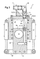
- eine Querschnittsansicht durch die Zuführvorrichtung der
Fig. 1 auf Höhe des Schieberelements bei geöffnetem Betonventil; - Fig. 4
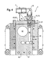
- eine Querschnittsansicht entsprechend
Fig. 3 bei geschlossenem Betonventil; - Fig. 5
- eine perspektivische Ansicht der Zuführvorrichtung aus
Fig. 1 bei geschlossenem Betonventil; und - Fig. 6
- die Anordnung der Zuführvorrichtung aus
Fig. 1 an einem Bohrgerät. - Ein Ausführungsbeispiel einer erfindungsgemäßen Zuführvorrichtung 1 ist in den
Figuren 1 bis 3 bei geöffnetem Betonventil 60 gezeigt. - Die Zuführvorrichtung 1 weist ein als Schieberventil ausgebildetes Betonventil 60 mit einem kastenförmigen Ventilgehäuse 63 auf. Auf einer vorderen Flachseite des Ventilgehäuses 63 ist ein als Flanschelement ausgebildeter Bohrstranganschluss 3 vorgesehen, über den eine Leitungsverbindung mit einem lediglich in
Fig. 6 schematisch dargestellten Bohrstrang 12 eines Endlosschneckenbohrers hergestellt werden kann. Auf der gegenüberliegenden, rückwärtigen Flachseite des Ventilgehäuses 63 ist ein als Rohrstutzen ausgebildeter Betonanschluss 6 vorgesehen, über den eine Leitungsverbindung mit einer Betonpumpe herstellbar ist (Fig. 2 ). Der Betonanschluss 6 und der Bohrstranganschluss 3 sind dabei auf gegenüberliegenden Seiten des Ventilgehäuses 63 zumindest annähernd koaxial angeordnet. Für eine besonders zuverlässige Verbindung mit einem Betonschlauch sind außenseitig am Rohrstutzen des Betonanschlusses 6 Halteringe vorgesehen. - Im Ventilgehäuse 63 des Betonventils 60 ist ein Schlitz 67 (
Fig. 3 ) gebildet, in welchem ein als Schieberplatte ausgebildetes Schieberelement 61 in vertikaler Richtung verstellbar angeordnet ist. Dieses Schieberelement 61 bildet den Absperrkörper des Betonventils 60. Im plattenförmigen Schieberelement 61 ist eine kreisförmige Durchgangsöffnung 62 vorgesehen. Die Durchgangsöffnung 62 ist dabei in einem oberen, ventilinnenseitigen Bereich des Schieberelementes 61 angeordnet. Bei dem in denFiguren 1 bis 3 dargestellten geöffneten Zustand des Betonventils 60 ist das Schieberelement 61 aus dem Ventilgehäuse 63 nach unten herausgefahren, so dass die Durchgangsöffnung 62 im Schieberelement 61 zumindest bereichsweise mit dem Bohrstranganschluss 3 sowie dem Betonanschluss 6 fluchtet, und daher einen Durchgang von Beton vom Betonanschluss 6 in den Bohrstranganschluss 3 und somit in den Bohrstrang 12 ermöglicht. - Zum Verstellen des Schieberelementes 61 im Schlitz 67, also zum Ein- und Ausfahren des Schieberelementes 61 in das beziehungsweise aus dem Ventilgehäuse 63, ist ein hydraulischer Ventilantrieb mit zwei Hydraulikzylindern 31 und 31' vorgesehen. Die beiden Hydraulikzylinder verlaufen beiderseits des Ventilgehäuses 63 parallel zueinander längs des Ventilgehäuses 63 von oben nach unten. Die Hydraulikzylinder 31, 31' sind einerseits in einem oberen Bereich des Ventilgehäuses 63 am Ventilgehäuse 63 befestigt, und andererseits an einem gemeinsamen Joch 33, welches unterhalb des Ventilgehäuses 63 verläuft, und an welchem das Schieberelement 61 befestigt, im dargestellten Ausführungsbeispiel verschraubt ist. Das Joch 33 besteht aus zwei Jochelementen 34, 34', zwischen denen das Schieberelement 61 angeordnet ist (
Fig. 1 ). Die beiden Jochelemente 34, 34' verlaufen parallel zueinander in horizontaler Richtung und sind beide jeweils an den Kolbenstangen beider Hydraulikzylinder 31, 31' befestigt. Durch Ein- und Ausfahren der Hydraulikzylinder 31, 31' wird das Joch 33 und das hiermit verbundene Schieberelement 61 entsprechend bewegt, und das Schieberelement 61 dabei bezüglich dem Ventilgehäuse 63 ein- oder ausgefahren. - Während die
Figuren 1 bis 3 den ausgefahrenen Zustand mit geöffnetem Betonventil 60 zeigen, zeigen dieFiguren 4 und5 den eingefahrenen Zustand des Schieberelementes 61. Wenn das Schieberelement 61 in das Ventilgehäuse 63 eingefahren ist, ist die Durchgangsöffnung 62 gegenüber den Anschlüssen 3 und 6 lateral versetzt, und ein Durchgang von Beton zwischen den Anschlüssen 3 und 6 wird von den Flachseiten 65, 65' des Schieberelementes 61, welches sich zwischen den Anschlüssen 3 und 6 befindet, gesperrt. - Zum Zuführen von Luft ist oberseitig an der Zuführvorrichtung 1 ein als Rohrstutzen ausgebildeter Gasanschluss 7 zum Anschluss an eine Druckluftquelle vorgesehen. Der Gasanschluss 7 ist über einen Rohrbogen 20 mit einem Gasventil 70 verbunden, welches oberseitig am Ventilgehäuse 63 des Betonventils 60 angeordnet ist. Das Gasventil 70 ist dabei als Sitzventil ausgebildet und weist einen vertikalen Leitungsverlauf auf, der rechtwinklig zum Leitungsabschnitt 68 (
Fig. 5 ), welcher mit dem Schieberelement absperrbar ist, also rechtwinklig zur Verbindungslinie zwischen Bohrstranganschluss 3 und Betonanschluss 6, verläuft. Aufgrund des Rohrbogens 20, welcher eine Leitungskrümmung von 90° zur Folge hat, ist trotz der vertikalen Leitungsanordnung am Gasventil 70 am Gasanschluss 7 ein horizontaler Leitungsverlauf gegeben, was einen besonders einfachen Schlauchanschluss am Gasanschluss 7 ermöglicht. - Das Gasventil 70 weist einen pilzförmigen Absperrkörper 71 auf, der in einem Ventilgehäuse 73 des Gasventils 70 längs verschiebbar angeordnet ist (
Figuren 3 und4 ). Zum Öffnen des Gasventils 70 ist am Schieberelement 61 des Betonventils 60 ein mechanisches Betätigungselement 80 vorgesehen. Das Betätigungselement 80 ist als zylindrischer Stößel ausgebildet und steht von einer rückseitigen, ventilinnenseitigen Schmalseite 69 des Schieberelementes 61, welche waagrecht verläuft und dem Gasventil 70 zugewandt ist, vor. Bei geschlossenem Betonventil 60, das heißt bei eingefahrenem Schieberelement 61, kommt das Betätigungselement 80 auf einer Kontaktfläche 78 des Absperrkörpers 71 des Gasventils 70 zu liegen und drückt dabei den Absperrkörper 71 von seinem Ventilsitz hinweg, so dass ein Gasdurchtritt durch das Gasventil 70 möglich ist. Dieser Zustand ist inFig. 4 dargestellt. - Die Kontaktfläche 78 ist stirnseitig auf der verbreiterten Seite des pilzförmigen Absperrkörpers 71 vorgesehen. Das Betätigungselement 80 dringt bei eingefahrenem Schieberelement 61 in den Auslasskanal 79 des Gasventils 70 ein und wirkt durch den Auslasskanal 79 hindurch auf die Kontaktfläche 78 und den Absperrkörper 71.
- Der Auslasskanal 79 des Gasventils 70 führt in den Schlitz 67 im Inneren des Ventilgehäuses 63 des Betonventils 60.
- Zum Weiterleiten des Gases, welches durch das geöffnete Gasventil 70 (
Fig. 4 ) hindurch in das Ventilgehäuse 63 des Betonventils 60 tritt, ist im Schieberelement 61 des Betonventils 60 ein Gaskanal 50 vorgesehen. Der Gaskanal 50 beginnt auf der betonventilinnenseitigen Schmalseite 69 und weist dort Gaseintrittsöffnungen 51, 51' auf, welche das Betätigungselement 80 umgeben, und welche bei eingefahrenem Schieberelement 61 vor dem Auslasskanal 79 des Gasventils 70 zu liegen kommen, so dass aus dem Auslasskanal 79 des Gasventils 70 austretendes Gas über die Gaseintrittsöffnungen 51, 51' in den Gaskanal 50 gelangt. - An demjenigen Ende, welches den Gaseintrittsöffnungen 51, 51' abgewandt ist, weist der Gaskanal 50 eine Gasaustrittsöffnung 52 auf, die in derjenigen Flachseite 65 des Schieberelementes 61 angeordnet ist, welche dem Bohrstranganschluss 3 zugewandt ist (
Fig. 5 ). Die Gasaustrittsöffnung 52 ist dabei nach unten versetzt zur Durchgangsöffnung 62 vorgesehen und so angeordnet, dass sie bei eingefahrenem Schieberelement 61 mit dem Bohrstranganschluss 3 koaxial fluchtet (Fig. 5 ). - Ist das Schieberelement 61 somit in das Ventilgehäuse 63 des Betonventils 60 eingefahren, so kann Gas vom Gasanschluss 7 über das durch das Betätigungselement 80 geöffnete Gasventil 70 und die Gaseintrittsöffnungen 51, 51' in den Gaskanal 50 gelangen, aus welchem das Gas an der Gasaustrittsöffnung 52 austritt und zum Bohrstranganschluss 3 und somit zum Bohrstrang 12 gelangt. Die Verbindung zwischen Betonanschluss 6 und Bohrstranganschluss 3 ist hingegen in diesem Zustand durch das Schieberelement 61 gesperrt, so dass im eingefahrenen Zustand des Schieberelements 61 ausschließlich Gas zum Bohrstranganschluss 3 und somit in den Bohrstrang 12 gelangen kann (
Fig. 4 ). - Wird das Schieberelement 61 hingegen aus dem Ventilgehäuse 63 herausgefahren (
Fig. 3 ), so wird das am Schieberelement 61 befestigte Betätigungselement 80 gleichzeitig vom Absperrkörper 71 des Gasventils 70 hinweg gefahren (Fig. 3 ). Der Absperrkörper 71 kann sich nun auf den Ventilsitz des Ventilgehäuses 73 des Gasventils 70 absenken und das Gasventil 70 für einen Gasdurchgang sperren (inFig. 3 ist der Absperrkörper 71 noch im offenen Zustand gezeigt, kurz bevor der Absperrkörper 71 schließt). Das Schließen des Absperrkörpers 71 kann beispielsweise aufgrund von Gasdruck am Gasanschluss 7 erfolgen. Es kann aber als Spanneinrichtung auch beispielsweise eine Schraubenfeder vorgesehen sein, welche den Schaft des pilzförmigen Absperrkörpers 71 umgibt. - Da das Betätigungselement 80 bei ausgefahrenem Schieberelement 61 nicht mehr auf den Absperrkörper 71 des Gasventils 70 wirkt, kann dieses schließen, so dass eine Gaszufuhr zwischen dem Gasanschluss 7 und dem Bohrstranganschluss 3 unterbrochen ist. Gleichzeitig ist ein Durchgang zwischen dem Betonanschluss 6 und dem Bohrstranganschluss 3 möglich, da die Durchgangsöffnung 62 in dieser Position zwischen den beiden Anschlüssen 6 und 3 zu liegen kommt. Somit ist sichergestellt, dass bei Einleitung von Beton in den Bohrstrang 12 die Gaszufuhr über den Gasanschluss 7 gesperrt ist.
- Bei ausgefahrenem Schieberelement 61 sind die Gaseintrittsöffnungen 51, 51' vom Auslasskanal 79 des Gasventils 70 beabstandet. Da in diesem Zustand das Gasventil 70 jedoch schließt, sind dennoch keine unerwünschten Gasverluste gegeben.
- Der Gaskanal 50 ist dreiteilig ausgebildet. Er weist einen ersten Abschnitt 54 auf, welcher vertikal, in Bewegungsrichtung des Schieberelementes 61 an der Durchgangsöffnung 62 vorbei verläuft. Hieran schließt sich rechtwinklig ein zweiter Abschnitt 54' an, welcher senkrecht zur Bewegungsrichtung horizontal längs der Flachseiten 65, 65' des Schieberelementes 61 verläuft. Hieran schließt sich rechtwinklig ein dritter Abschnitt 54" an, welcher horizontal, senkrecht zur Bewegungsrichtung des Schieberelementes 61 und senkrecht zu den Flachseiten 65, 65' verläuft, und an dem die Gasaustrittsöffnung 52 angeordnet ist (
Fig. 5 ). Die Abschnitte 54, 54' und 54" sind jeweils als Bohrungen ausgebildet. - Beim Betrieb der Zuführvorrichtung 1 werden die Hydraulikzylinder 31, 31' betätigt und dabei das Schieberelement 61, welches den Absperrkörper des Betonventils 60 bildet, aus dem Ventilgehäuse 63 des Betonventils 60 ausgefahren beziehungsweise in das Ventilgehäuse 63 eingefahren. Hierbei gibt die Durchgangsöffnung 62 einen Durchgang zwischen Betonanschluss 6 und Bohrstranganschluss 3 frei beziehungsweise sperrt ihn. Das Gasventil 70 wird dabei gesperrt beziehungsweise über das Betätigungselement 80 für eine Gasverbindung zwischen dem Gasanschluss 7 und dem Bohrstranganschluss 3 freigegeben. Da das Betätigungselement 80 am Schieberelement 61 angeordnet ist, ist sichergestellt, dass das Betonventil 60 und das Gasventil 70 synchron in gegensätzlicher Weise geschaltet werden, so dass entweder der Betonanschluss 6 oder der Gasanschluss 7 mit dem Bohrstranganschluss 3 in Verbindung steht, jedoch niemals beide Anschlüsse 6, 7 gleichzeitig.
-
Fig. 6 zeigt die Anordnung der Zuführvorrichtung 1 derFiguren 1 bis 5 am Mastkopf eines Trägerfahrzeugs 10, von dem der Übersichtlichkeit halber lediglich der Mast dargestellt ist. Am Mast des Trägerfahrzeugs 10 ist dabei ein Bohrantrieb 11 zum drehenden Antreiben des lediglich schematisch dargestellten Bohrstrangs 12 vorgesehen. Die Zuführvorrichtung 1 ist oberhalb des Bohrantriebes 11 angeordnet. Der still stehende Bohrstranganschluss 3 der still stehenden Zuführvorrichtung 1 steht mit dem rotierenden Bohrstrang 12 über eine Drehdurchführung 15 in Leitungsverbindung, welche oberhalb des Bohrantriebs 11 angeordnet ist. InFig. 6 ist auch ein Betonschlauch 16 dargestellt, welcher zum Herstellen einer Leitungsverbindung mit einer Betonpumpe am Betonanschluss 6 angeflanscht ist.
Claims (15)
- Zuführvorrichtung (1) zum Zuführen von Beton und Gas in den Bohrstrang (12) eines Bohrgerätes beim Erstellen eines betonierten Bohrlochs, mit- zumindest einem Bohrstranganschluss (3) zum Anschließen an den Bohrstrang (12),- einem Betonanschluss (6) zum Anschließen an eine Betonfördereinrichtung,- einem Gasanschluss (7) zum Anschließen an eine Druckgasquelle,- einer Leitungsanordnung, über welche der Betonanschluss (6) und der Gasanschluss (7) mit dem Bohrstranganschluss (3) verbunden sind,- einem Betonventil (60), welches in der Leitungsanordnung vorgesehen ist, und mit welchem eine Verbindung zwischen dem Betonanschluss (6) und dem Bohrstranganschluss (3) absperrbar ist, und- einem Gasventil (70), welches in der Leitungsanordnung vorgesehen ist, und mit welchem eine Verbindung zwischen dem Gasanschluss (7) und dem Bohrstranganschluss (3) absperrbar ist,
dadurch gekennzeichnet,- dass das Betonventil (60) ein mechanisches Betätigungselement (80) zum Betätigen des Gasventils (70) aufweist,- wobei das mechanische Betätigungselement (80) derart angeordnet ist, dass das Gasventil (70) abgesperrt wird, wenn das Betonventil (60) geöffnet wird. - Zuführvorrichtung (1) nach Anspruch 1,
dadurch gekennzeichnet,
dass das mechanische Betätigungselement (80) derart angeordnet ist, dass das Gasventil (70) öffnet, wenn das Betonventil (60) abgesperrt wird. - Zuführvorrichtung (1) einem der vorstehenden Ansprüche,
dadurch gekennzeichnet,
dass das Betonventil (60) ein Schieberventil mit einem Schieberelement (61) ist, wobei das Schieberelement (61) als Schieberplatte ausgebildet ist. - Zuführvorrichtung (1) nach einem der vorstehenden Ansprüche,
dadurch gekennzeichnet,
dass das mechanische Betätigungselement (80) ein Stößel ist, und
dass das mechanische Betätigungselement (80) am Betonventil (60) angeordnet ist. - Zuführvorrichtung (1) nach einem der vorstehenden Ansprüche,
dadurch gekennzeichnet,
dass das mechanische Betätigungselement (80) an einer betonventilinnenseitigen Schmalseite (69) des Schieberelements (61) angeordnet ist. - Zuführvorrichtung (1) einem der vorstehenden Ansprüche,
dadurch gekennzeichnet,
dass das Gasventil (70) ein Sitzventil ist. - Zuführvorrichtung (1) einem der vorstehenden Ansprüche,
dadurch gekennzeichnet,
dass eine Spanneinrichtung vorgesehen ist, die das Gasventil (70) in einem abgesperrten Zustand hält. - Zuführvorrichtung (1) einem der vorstehenden Ansprüche,
dadurch gekennzeichnet,
dass ein Absperrkörper (71) des Gasventils (70) eine Kontaktfläche (78) für das mechanische Betätigungselement (80) aufweist, die bevorzugt einem Auslasskanal (79) des Gasventils (70) zugewandt ist, und
dass das mechanische Betätigungselement (80) zumindest bei geöffnetem Gasventil (70) im Auslasskanal (79) des Gasventils (70), insbesondere koaxial zum Auslasskanal (79), angeordnet ist. - Zuführvorrichtung (1) nach einem der Ansprüche 3 bis 8,
dadurch gekennzeichnet,
dass im Schieberelement (61) des Betonventils (60) ein Gaskanal (50) zum Zuleiten des Gases zum Bohrstranganschluss (3) vorgesehen ist,
wobei der Gaskanal (50) zumindest eine Gaseintrittsöffnung (51) aufweist, welche an einer Schmalseite (69) des Schieberelementes (61) angeordnet ist, und
wobei der Gaskanal (50) eine Gasaustrittsöffnung (52) aufweist, welche an einer Flachseite (65) des Schieberelementes (61) angeordnet ist. - Zuführvorrichtung (1) nach Anspruch 9,
dadurch gekennzeichnet,
dass das mechanische Betätigungselement (80) im Bereich der zumindest einen Gaseintrittsöffnung (51) des Gaskanals (50) am Schieberelement (61) angeordnet ist, wobei das mechanische Betätigungselement (80) insbesondere von Gaseintrittsöffnungen (51, 51) umgeben ist. - Zuführvorrichtung (1) nach einem der vorstehenden Ansprüche,
dadurch gekennzeichnet,
dass das Schieberelement (61) für die Verbindung zwischen dem Betonanschluss (6) und dem Bohrstranganschluss (3) eine vorzugsweise kreisförmige Durchgangsöffnung (62) aufweist. - Zuführvorrichtung (1) nach einem der vorstehenden Ansprüche,
dadurch gekennzeichnet,
dass der Betonanschluss (6) und der Bohrstranganschluss (3) auf gegenüberliegenden Seiten eines Ventilgehäuses (63) des Betonventils (60), insbesondere koaxial zueinander angeordnet sind. - Zuführvorrichtung (1) nach einem der Ansprüche 3 bis 12,
dadurch gekennzeichnet,
dass zum Betätigen des Betonventils (60) ein Ventilantrieb vorgesehen ist,
wobei der Ventilantrieb zwei Hydraulikzylinder (31, 31') aufweist, die beiderseits des Schieberelements (61) angeordnet sind, wobei die Hydraulikzylinder (31, 31') über ein Joch (33) verbunden sind, an welchem das Schieberelement (61) angeordnet ist. - Bohrgerät mit
einem Trägerfahrzeug (10), an welchem ein Bohrantrieb (11) zum Antreiben eines Bohrstranges (12) angeordnet ist,
dadurch gekennzeichnet,
dass eine Zuführvorrichtung (1) zum Zuführen von Beton und Gas in den Bohrstrang (12) nach einem der vorstehenden Ansprüche vorgesehen ist. - Verfahren zum Erstellen eines betonierten Bohrlochs, bei dem- mittels eines Bohrantriebes (11) ein Bohrstrang (12) in den Boden eingefahren wird, und- der Bohrstrang (12) anschließend gezogen wird und das hierbei freiwerdende Bohrloch über den Bohrstrang (12) mit Beton verfüllt wird,- wobei beim Einfahren des Bohrstrangs (12) der Bohrstrang (12) durch Zufuhr von Gas in den Bohrstrang (12) unter Gasüberdruck gesetzt wird,
dadurch gekennzeichnet,- dass am Bohrgerät eine Zuführvorrichtung (1) nach einem der Ansprüche 1 bis 13 vorgesehen wird, und dass mittels der Zuführvorrichtung (1) die Zufuhr von Gas in den Bohrstrang (12) unterbrochen wird, wenn Beton in den Bohrstrang (12) eingeleitet wird.
Priority Applications (4)
| Application Number | Priority Date | Filing Date | Title |
|---|---|---|---|
| ES09001400T ES2397243T3 (es) | 2009-02-02 | 2009-02-02 | Dispositivo de suministro para el suministro de hormigón y gas al tramo de perforación de un aparato de perforación durante la creación de un orificio de perforación hormigonado y procedimiento para la creación de un orificio de perforación hormigonado |
| EP20090001400 EP2213802B1 (de) | 2009-02-02 | 2009-02-02 | Zuführvorrichtung zum Zuführen von Beton und Gas in den Bohrstrang eines Bohrgerätes beim Erstellen eines betonierten Bohrlochs und Verfahren zum Erstellen eines betonierten Bohrlochs |
| BRPI1001378 BRPI1001378A2 (pt) | 2009-02-02 | 2010-02-02 | dispositivo de alimentação para alimentar concreto e gás para a coluna de perfuração de uma unidade de perfuração durante a formação de um furo de sondagem concretado, e método para formar um furo de sondagem concretado |
| CN 201010138173 CN101798904B (zh) | 2009-02-02 | 2010-02-02 | 混凝土钻孔形成法及钻孔时向钻机柱供混凝土与气的装置 |
Applications Claiming Priority (1)
| Application Number | Priority Date | Filing Date | Title |
|---|---|---|---|
| EP20090001400 EP2213802B1 (de) | 2009-02-02 | 2009-02-02 | Zuführvorrichtung zum Zuführen von Beton und Gas in den Bohrstrang eines Bohrgerätes beim Erstellen eines betonierten Bohrlochs und Verfahren zum Erstellen eines betonierten Bohrlochs |
Publications (2)
| Publication Number | Publication Date |
|---|---|
| EP2213802A1 true EP2213802A1 (de) | 2010-08-04 |
| EP2213802B1 EP2213802B1 (de) | 2012-10-10 |
Family
ID=40726451
Family Applications (1)
| Application Number | Title | Priority Date | Filing Date |
|---|---|---|---|
| EP20090001400 Active EP2213802B1 (de) | 2009-02-02 | 2009-02-02 | Zuführvorrichtung zum Zuführen von Beton und Gas in den Bohrstrang eines Bohrgerätes beim Erstellen eines betonierten Bohrlochs und Verfahren zum Erstellen eines betonierten Bohrlochs |
Country Status (4)
| Country | Link |
|---|---|
| EP (1) | EP2213802B1 (de) |
| CN (1) | CN101798904B (de) |
| BR (1) | BRPI1001378A2 (de) |
| ES (1) | ES2397243T3 (de) |
Citations (4)
| Publication number | Priority date | Publication date | Assignee | Title |
|---|---|---|---|---|
| FR1311548A (fr) * | 1961-12-22 | 1962-12-07 | Raymond Int Inc | Procédé et appareil pour la pose de pilots |
| DE3208492A1 (de) * | 1982-03-09 | 1983-09-15 | Kabushiki Kaisha Komatsu Seisakusho, Tokyo | Verfahren und vorrichtung zum einbringen von hohlpfaehlen in den boden |
| GB2116614A (en) * | 1982-03-12 | 1983-09-28 | Komatsu Mfg Co Ltd | Method and apparatus for driving hollow piles into the ground |
| WO2004018781A1 (en) * | 2002-08-23 | 2004-03-04 | Soilex Ab | A method of making a pile or an earth anchor |
Family Cites Families (3)
| Publication number | Priority date | Publication date | Assignee | Title |
|---|---|---|---|---|
| CN1078282A (zh) * | 1992-05-08 | 1993-11-10 | 东北金城建筑安装工程总公司地基基础工程处 | 钻孔灌注桩桩底压浆工艺及其专用钢筋笼 |
| CN1062045C (zh) * | 1997-12-26 | 2001-02-14 | 秦忠泽 | 一种现场灌注桩的施工方法 |
| CN200952348Y (zh) * | 2006-08-02 | 2007-09-26 | 杨修霞 | 带有溢流装置的长螺旋钻孔机 |
-
2009
- 2009-02-02 EP EP20090001400 patent/EP2213802B1/de active Active
- 2009-02-02 ES ES09001400T patent/ES2397243T3/es active Active
-
2010
- 2010-02-02 CN CN 201010138173 patent/CN101798904B/zh active Active
- 2010-02-02 BR BRPI1001378 patent/BRPI1001378A2/pt not_active IP Right Cessation
Patent Citations (4)
| Publication number | Priority date | Publication date | Assignee | Title |
|---|---|---|---|---|
| FR1311548A (fr) * | 1961-12-22 | 1962-12-07 | Raymond Int Inc | Procédé et appareil pour la pose de pilots |
| DE3208492A1 (de) * | 1982-03-09 | 1983-09-15 | Kabushiki Kaisha Komatsu Seisakusho, Tokyo | Verfahren und vorrichtung zum einbringen von hohlpfaehlen in den boden |
| GB2116614A (en) * | 1982-03-12 | 1983-09-28 | Komatsu Mfg Co Ltd | Method and apparatus for driving hollow piles into the ground |
| WO2004018781A1 (en) * | 2002-08-23 | 2004-03-04 | Soilex Ab | A method of making a pile or an earth anchor |
Also Published As
| Publication number | Publication date |
|---|---|
| BRPI1001378A2 (pt) | 2011-06-28 |
| CN101798904B (zh) | 2013-06-19 |
| ES2397243T3 (es) | 2013-03-05 |
| CN101798904A (zh) | 2010-08-11 |
| EP2213802B1 (de) | 2012-10-10 |
Similar Documents
| Publication | Publication Date | Title |
|---|---|---|
| DE3122552C2 (de) | Steuerwerkzeug für Drehbohrstränge | |
| DE102008003968B3 (de) | Bohranlage | |
| EP2505762B1 (de) | Bohrvorrichtung und Verfahren zum Horizontalbohren | |
| DE2820785C2 (de) | Ventilsteuerung für Rammbohrgeräte | |
| EP0365612B1 (de) | Bohrgerät | |
| DE60125160T2 (de) | Vorrichtung und verfahren zum richtbohren | |
| EP2553202B1 (de) | Verfahren zum betrieb einer horizontalbohrvorrichtung und horizontalbohrvorrichtung | |
| EP3126094B1 (de) | Wasser-abrasiv-suspensions-schneidanlage | |
| DE2232993C2 (de) | Schneidvorrichtung zum Einschneiden von Schlitzen in eine Gesteinsoberfläche durch Flüssigkeitsstrahlen | |
| DE102013014837B4 (de) | Verfahren und Vorrichtung zum Entfernen von Bodenmaterial vor der Vorderwand einer Schildvortriebsmaschine (SVM) | |
| DE102015110113B4 (de) | Absperrschieber | |
| DE2653185A1 (de) | Gesteuertes richtungsbohrwerkzeug | |
| DE102009038385B4 (de) | Rammbohrvorrichtung mit einem pneumatischen Antrieb und einer hydraulischen Umsteuerung der Bewegungsrichtung | |
| DE19858519A1 (de) | Pneumatisch umsteuerbares Rammbohrgerät | |
| EP2213802B1 (de) | Zuführvorrichtung zum Zuführen von Beton und Gas in den Bohrstrang eines Bohrgerätes beim Erstellen eines betonierten Bohrlochs und Verfahren zum Erstellen eines betonierten Bohrlochs | |
| EP3091173A1 (de) | Bohranlage zum erzeugen oder aufweiten einer erdbohrung im erdreich und verfahren zur steuerung eines vorschubantriebs einer solchen bohranlage | |
| EP2626506B1 (de) | Vorrichtung zum Bewegen eines Arbeitsmittels im Erdreich | |
| DE19533281C2 (de) | Vorrichtung zum Vortrieb von Hohlprofilen in den Baugrund | |
| DE102015008339A1 (de) | "Rammbohrvorrichtung und Verfahren zum Umsteuern einer Rammbohrvorrichtung" | |
| DE10150904C1 (de) | Bohr- und Ankersetzgerät | |
| DE102007015088B4 (de) | Verfahren zum mehrstufigen Herstellen einer Erdbohrung und Vorrichtung zur Durchführung des Verfahrens | |
| DE202007007036U1 (de) | Mikrobreitenverstellbare Schlitzdüse | |
| EP3190257B1 (de) | Bohrvorrichtung und verfahren zum herstellen eines bohrpfahls im boden | |
| DE2415645A1 (de) | Hydromechanischer steuermechanismus | |
| DE102011107822B4 (de) | Verschlussvorrichtung für einen defekten Blowout-Preventer |
Legal Events
| Date | Code | Title | Description |
|---|---|---|---|
| PUAI | Public reference made under article 153(3) epc to a published international application that has entered the european phase |
Free format text: ORIGINAL CODE: 0009012 |
|
| 17P | Request for examination filed |
Effective date: 20091229 |
|
| AK | Designated contracting states |
Kind code of ref document: A1 Designated state(s): AT BE BG CH CY CZ DE DK EE ES FI FR GB GR HR HU IE IS IT LI LT LU LV MC MK MT NL NO PL PT RO SE SI SK TR |
|
| AX | Request for extension of the european patent |
Extension state: AL BA RS |
|
| AKX | Designation fees paid |
Designated state(s): AT BE BG CH CY CZ DE DK EE ES FI FR GB GR HR HU IE IS IT LI LT LU LV MC MK MT NL NO PL PT RO SE SI SK TR |
|
| GRAP | Despatch of communication of intention to grant a patent |
Free format text: ORIGINAL CODE: EPIDOSNIGR1 |
|
| GRAJ | Information related to disapproval of communication of intention to grant by the applicant or resumption of examination proceedings by the epo deleted |
Free format text: ORIGINAL CODE: EPIDOSDIGR1 |
|
| GRAP | Despatch of communication of intention to grant a patent |
Free format text: ORIGINAL CODE: EPIDOSNIGR1 |
|
| GRAS | Grant fee paid |
Free format text: ORIGINAL CODE: EPIDOSNIGR3 |
|
| RAP1 | Party data changed (applicant data changed or rights of an application transferred) |
Owner name: BAUER MASCHINEN GMBH |
|
| GRAA | (expected) grant |
Free format text: ORIGINAL CODE: 0009210 |
|
| AK | Designated contracting states |
Kind code of ref document: B1 Designated state(s): AT BE BG CH CY CZ DE DK EE ES FI FR GB GR HR HU IE IS IT LI LT LU LV MC MK MT NL NO PL PT RO SE SI SK TR |
|
| REG | Reference to a national code |
Ref country code: GB Ref legal event code: FG4D Free format text: NOT ENGLISH |
|
| REG | Reference to a national code |
Ref country code: AT Ref legal event code: REF Ref document number: 579048 Country of ref document: AT Kind code of ref document: T Effective date: 20121015 Ref country code: CH Ref legal event code: EP |
|
| REG | Reference to a national code |
Ref country code: IE Ref legal event code: FG4D Free format text: LANGUAGE OF EP DOCUMENT: GERMAN |
|
| REG | Reference to a national code |
Ref country code: DE Ref legal event code: R096 Ref document number: 502009005003 Country of ref document: DE Effective date: 20121206 |
|
| PG25 | Lapsed in a contracting state [announced via postgrant information from national office to epo] |
Ref country code: SI Free format text: LAPSE BECAUSE OF FAILURE TO SUBMIT A TRANSLATION OF THE DESCRIPTION OR TO PAY THE FEE WITHIN THE PRESCRIBED TIME-LIMIT Effective date: 20121010 |
|
| REG | Reference to a national code |
Ref country code: ES Ref legal event code: FG2A Ref document number: 2397243 Country of ref document: ES Kind code of ref document: T3 Effective date: 20130305 |
|
| REG | Reference to a national code |
Ref country code: NL Ref legal event code: VDEP Effective date: 20121010 |
|
| REG | Reference to a national code |
Ref country code: LT Ref legal event code: MG4D |
|
| PG25 | Lapsed in a contracting state [announced via postgrant information from national office to epo] |
Ref country code: NL Free format text: LAPSE BECAUSE OF FAILURE TO SUBMIT A TRANSLATION OF THE DESCRIPTION OR TO PAY THE FEE WITHIN THE PRESCRIBED TIME-LIMIT Effective date: 20121010 Ref country code: NO Free format text: LAPSE BECAUSE OF FAILURE TO SUBMIT A TRANSLATION OF THE DESCRIPTION OR TO PAY THE FEE WITHIN THE PRESCRIBED TIME-LIMIT Effective date: 20130110 Ref country code: IS Free format text: LAPSE BECAUSE OF FAILURE TO SUBMIT A TRANSLATION OF THE DESCRIPTION OR TO PAY THE FEE WITHIN THE PRESCRIBED TIME-LIMIT Effective date: 20130210 Ref country code: SE Free format text: LAPSE BECAUSE OF FAILURE TO SUBMIT A TRANSLATION OF THE DESCRIPTION OR TO PAY THE FEE WITHIN THE PRESCRIBED TIME-LIMIT Effective date: 20121010 Ref country code: HR Free format text: LAPSE BECAUSE OF FAILURE TO SUBMIT A TRANSLATION OF THE DESCRIPTION OR TO PAY THE FEE WITHIN THE PRESCRIBED TIME-LIMIT Effective date: 20121010 Ref country code: LT Free format text: LAPSE BECAUSE OF FAILURE TO SUBMIT A TRANSLATION OF THE DESCRIPTION OR TO PAY THE FEE WITHIN THE PRESCRIBED TIME-LIMIT Effective date: 20121010 |
|
| PG25 | Lapsed in a contracting state [announced via postgrant information from national office to epo] |
Ref country code: PT Free format text: LAPSE BECAUSE OF FAILURE TO SUBMIT A TRANSLATION OF THE DESCRIPTION OR TO PAY THE FEE WITHIN THE PRESCRIBED TIME-LIMIT Effective date: 20130211 Ref country code: LV Free format text: LAPSE BECAUSE OF FAILURE TO SUBMIT A TRANSLATION OF THE DESCRIPTION OR TO PAY THE FEE WITHIN THE PRESCRIBED TIME-LIMIT Effective date: 20121010 Ref country code: GR Free format text: LAPSE BECAUSE OF FAILURE TO SUBMIT A TRANSLATION OF THE DESCRIPTION OR TO PAY THE FEE WITHIN THE PRESCRIBED TIME-LIMIT Effective date: 20130111 Ref country code: PL Free format text: LAPSE BECAUSE OF FAILURE TO SUBMIT A TRANSLATION OF THE DESCRIPTION OR TO PAY THE FEE WITHIN THE PRESCRIBED TIME-LIMIT Effective date: 20121010 |
|
| PG25 | Lapsed in a contracting state [announced via postgrant information from national office to epo] |
Ref country code: SK Free format text: LAPSE BECAUSE OF FAILURE TO SUBMIT A TRANSLATION OF THE DESCRIPTION OR TO PAY THE FEE WITHIN THE PRESCRIBED TIME-LIMIT Effective date: 20121010 Ref country code: EE Free format text: LAPSE BECAUSE OF FAILURE TO SUBMIT A TRANSLATION OF THE DESCRIPTION OR TO PAY THE FEE WITHIN THE PRESCRIBED TIME-LIMIT Effective date: 20121010 Ref country code: BG Free format text: LAPSE BECAUSE OF FAILURE TO SUBMIT A TRANSLATION OF THE DESCRIPTION OR TO PAY THE FEE WITHIN THE PRESCRIBED TIME-LIMIT Effective date: 20130110 Ref country code: DK Free format text: LAPSE BECAUSE OF FAILURE TO SUBMIT A TRANSLATION OF THE DESCRIPTION OR TO PAY THE FEE WITHIN THE PRESCRIBED TIME-LIMIT Effective date: 20121010 Ref country code: CZ Free format text: LAPSE BECAUSE OF FAILURE TO SUBMIT A TRANSLATION OF THE DESCRIPTION OR TO PAY THE FEE WITHIN THE PRESCRIBED TIME-LIMIT Effective date: 20121010 |
|
| PLBE | No opposition filed within time limit |
Free format text: ORIGINAL CODE: 0009261 |
|
| STAA | Information on the status of an ep patent application or granted ep patent |
Free format text: STATUS: NO OPPOSITION FILED WITHIN TIME LIMIT |
|
| PG25 | Lapsed in a contracting state [announced via postgrant information from national office to epo] |
Ref country code: RO Free format text: LAPSE BECAUSE OF FAILURE TO SUBMIT A TRANSLATION OF THE DESCRIPTION OR TO PAY THE FEE WITHIN THE PRESCRIBED TIME-LIMIT Effective date: 20121010 |
|
| BERE | Be: lapsed |
Owner name: BAUER MASCHINEN G.M.B.H. Effective date: 20130228 |
|
| 26N | No opposition filed |
Effective date: 20130711 |
|
| PG25 | Lapsed in a contracting state [announced via postgrant information from national office to epo] |
Ref country code: MC Free format text: LAPSE BECAUSE OF NON-PAYMENT OF DUE FEES Effective date: 20130228 |
|
| REG | Reference to a national code |
Ref country code: CH Ref legal event code: PL |
|
| PG25 | Lapsed in a contracting state [announced via postgrant information from national office to epo] |
Ref country code: LI Free format text: LAPSE BECAUSE OF NON-PAYMENT OF DUE FEES Effective date: 20130228 Ref country code: CH Free format text: LAPSE BECAUSE OF NON-PAYMENT OF DUE FEES Effective date: 20130228 |
|
| REG | Reference to a national code |
Ref country code: DE Ref legal event code: R097 Ref document number: 502009005003 Country of ref document: DE Effective date: 20130711 |
|
| PG25 | Lapsed in a contracting state [announced via postgrant information from national office to epo] |
Ref country code: CY Free format text: LAPSE BECAUSE OF FAILURE TO SUBMIT A TRANSLATION OF THE DESCRIPTION OR TO PAY THE FEE WITHIN THE PRESCRIBED TIME-LIMIT Effective date: 20121010 |
|
| REG | Reference to a national code |
Ref country code: IE Ref legal event code: MM4A |
|
| PG25 | Lapsed in a contracting state [announced via postgrant information from national office to epo] |
Ref country code: IE Free format text: LAPSE BECAUSE OF NON-PAYMENT OF DUE FEES Effective date: 20130202 Ref country code: BE Free format text: LAPSE BECAUSE OF NON-PAYMENT OF DUE FEES Effective date: 20130228 |
|
| PGFP | Annual fee paid to national office [announced via postgrant information from national office to epo] |
Ref country code: FI Payment date: 20140218 Year of fee payment: 6 |
|
| PG25 | Lapsed in a contracting state [announced via postgrant information from national office to epo] |
Ref country code: MT Free format text: LAPSE BECAUSE OF FAILURE TO SUBMIT A TRANSLATION OF THE DESCRIPTION OR TO PAY THE FEE WITHIN THE PRESCRIBED TIME-LIMIT Effective date: 20121010 |
|
| REG | Reference to a national code |
Ref country code: AT Ref legal event code: MM01 Ref document number: 579048 Country of ref document: AT Kind code of ref document: T Effective date: 20140202 |
|
| PG25 | Lapsed in a contracting state [announced via postgrant information from national office to epo] |
Ref country code: AT Free format text: LAPSE BECAUSE OF NON-PAYMENT OF DUE FEES Effective date: 20140202 |
|
| PG25 | Lapsed in a contracting state [announced via postgrant information from national office to epo] |
Ref country code: TR Free format text: LAPSE BECAUSE OF FAILURE TO SUBMIT A TRANSLATION OF THE DESCRIPTION OR TO PAY THE FEE WITHIN THE PRESCRIBED TIME-LIMIT Effective date: 20121010 |
|
| PG25 | Lapsed in a contracting state [announced via postgrant information from national office to epo] |
Ref country code: HU Free format text: LAPSE BECAUSE OF FAILURE TO SUBMIT A TRANSLATION OF THE DESCRIPTION OR TO PAY THE FEE WITHIN THE PRESCRIBED TIME-LIMIT; INVALID AB INITIO Effective date: 20090202 Ref country code: MK Free format text: LAPSE BECAUSE OF FAILURE TO SUBMIT A TRANSLATION OF THE DESCRIPTION OR TO PAY THE FEE WITHIN THE PRESCRIBED TIME-LIMIT Effective date: 20121010 Ref country code: LU Free format text: LAPSE BECAUSE OF NON-PAYMENT OF DUE FEES Effective date: 20130202 |
|
| PG25 | Lapsed in a contracting state [announced via postgrant information from national office to epo] |
Ref country code: FI Free format text: LAPSE BECAUSE OF NON-PAYMENT OF DUE FEES Effective date: 20150202 |
|
| REG | Reference to a national code |
Ref country code: FR Ref legal event code: PLFP Year of fee payment: 8 |
|
| REG | Reference to a national code |
Ref country code: FR Ref legal event code: PLFP Year of fee payment: 9 |
|
| PGFP | Annual fee paid to national office [announced via postgrant information from national office to epo] |
Ref country code: ES Payment date: 20170220 Year of fee payment: 9 |
|
| REG | Reference to a national code |
Ref country code: FR Ref legal event code: PLFP Year of fee payment: 10 |
|
| REG | Reference to a national code |
Ref country code: DE Ref legal event code: R082 Ref document number: 502009005003 Country of ref document: DE Representative=s name: WUNDERLICH & HEIM PATENTANWAELTE PARTNERSCHAFT, DE |
|
| REG | Reference to a national code |
Ref country code: ES Ref legal event code: FD2A Effective date: 20190801 |
|
| PG25 | Lapsed in a contracting state [announced via postgrant information from national office to epo] |
Ref country code: ES Free format text: LAPSE BECAUSE OF NON-PAYMENT OF DUE FEES Effective date: 20180203 |
|
| P01 | Opt-out of the competence of the unified patent court (upc) registered |
Effective date: 20230510 |
|
| PGFP | Annual fee paid to national office [announced via postgrant information from national office to epo] |
Ref country code: GB Payment date: 20260224 Year of fee payment: 18 |
|
| PGFP | Annual fee paid to national office [announced via postgrant information from national office to epo] |
Ref country code: DE Payment date: 20260218 Year of fee payment: 18 |
|
| PGFP | Annual fee paid to national office [announced via postgrant information from national office to epo] |
Ref country code: IT Payment date: 20260219 Year of fee payment: 18 |
|
| PGFP | Annual fee paid to national office [announced via postgrant information from national office to epo] |
Ref country code: FR Payment date: 20260225 Year of fee payment: 18 |