EP2213632A1 - Device for scoring glass sheet - Google Patents
Device for scoring glass sheet Download PDFInfo
- Publication number
- EP2213632A1 EP2213632A1 EP08844121A EP08844121A EP2213632A1 EP 2213632 A1 EP2213632 A1 EP 2213632A1 EP 08844121 A EP08844121 A EP 08844121A EP 08844121 A EP08844121 A EP 08844121A EP 2213632 A1 EP2213632 A1 EP 2213632A1
- Authority
- EP
- European Patent Office
- Prior art keywords
- glass sheet
- cutting line
- cutter
- glass
- cutting
- Prior art date
- Legal status (The legal status is an assumption and is not a legal conclusion. Google has not performed a legal analysis and makes no representation as to the accuracy of the status listed.)
- Withdrawn
Links
Images

Classifications
-
- C—CHEMISTRY; METALLURGY
- C03—GLASS; MINERAL OR SLAG WOOL
- C03B—MANUFACTURE, SHAPING, OR SUPPLEMENTARY PROCESSES
- C03B33/00—Severing cooled glass
- C03B33/02—Cutting or splitting sheet glass or ribbons; Apparatus or machines therefor
- C03B33/023—Cutting or splitting sheet glass or ribbons; Apparatus or machines therefor the sheet or ribbon being in a horizontal position
- C03B33/027—Scoring tool holders; Driving mechanisms therefor
-
- B—PERFORMING OPERATIONS; TRANSPORTING
- B28—WORKING CEMENT, CLAY, OR STONE
- B28D—WORKING STONE OR STONE-LIKE MATERIALS
- B28D1/00—Working stone or stone-like materials, e.g. brick, concrete or glass, not provided for elsewhere; Machines, devices, tools therefor
- B28D1/22—Working stone or stone-like materials, e.g. brick, concrete or glass, not provided for elsewhere; Machines, devices, tools therefor by cutting, e.g. incising
- B28D1/225—Working stone or stone-like materials, e.g. brick, concrete or glass, not provided for elsewhere; Machines, devices, tools therefor by cutting, e.g. incising for scoring or breaking, e.g. tiles
-
- C—CHEMISTRY; METALLURGY
- C03—GLASS; MINERAL OR SLAG WOOL
- C03B—MANUFACTURE, SHAPING, OR SUPPLEMENTARY PROCESSES
- C03B33/00—Severing cooled glass
- C03B33/02—Cutting or splitting sheet glass or ribbons; Apparatus or machines therefor
- C03B33/023—Cutting or splitting sheet glass or ribbons; Apparatus or machines therefor the sheet or ribbon being in a horizontal position
- C03B33/0235—Ribbons
-
- C—CHEMISTRY; METALLURGY
- C03—GLASS; MINERAL OR SLAG WOOL
- C03B—MANUFACTURE, SHAPING, OR SUPPLEMENTARY PROCESSES
- C03B33/00—Severing cooled glass
- C03B33/10—Glass-cutting tools, e.g. scoring tools
-
- Y—GENERAL TAGGING OF NEW TECHNOLOGICAL DEVELOPMENTS; GENERAL TAGGING OF CROSS-SECTIONAL TECHNOLOGIES SPANNING OVER SEVERAL SECTIONS OF THE IPC; TECHNICAL SUBJECTS COVERED BY FORMER USPC CROSS-REFERENCE ART COLLECTIONS [XRACs] AND DIGESTS
- Y10—TECHNICAL SUBJECTS COVERED BY FORMER USPC
- Y10T—TECHNICAL SUBJECTS COVERED BY FORMER US CLASSIFICATION
- Y10T83/00—Cutting
- Y10T83/02—Other than completely through work thickness
- Y10T83/0333—Scoring
- Y10T83/0348—Active means to control depth of score
Definitions
- the present invention relates to an apparatus for providing a cutting line on a glass sheet which provides a uniform cutting line for cutting a broad glass ribbon formed and conveyed by a float method, particularly a thin glass sheet having a thickness of 2 mm or less, with a predetermined dimension, without damaging the glass sheet.
- a glass ribbon formed by a float method is conveyed on a conveying roll in an annealing step and an inspection step, cutting lines in required size positions in longitudinal and lateral directions are provided thereon, and then the glass ribbon is cut by bend-cutting, whereby glass sheets of the required size are obtained.
- the glass ribbon is frequently conveyed in a meandering state in a width direction, or in an up-down undulant state which is so-called wave state due to various factors received during a conveyance.
- a thin sheet glass of 2 mm or less in thickness is required as a glass sheet for display.
- the glass ribbon formed into a glass sheet of 0.4 to 1.1 mm in thickness by the float method is very thin, the great wave-shaped undulation in the up-down direction is produced in the glass ribbon conveyed through the annealing step.
- vicinities of the both end portions in the width direction thereof have the large sheet-thickness out of a standard range.
- a cutting line providing apparatus for sheet glass which is used for providing a cutting line on the upper surface of a sheet glass placed horizontally has been disclosed.
- the apparatus includes a main frame that is movable in a cutting line providing direction, a sub-frame that is provided for the main frame slidably in the up-down direction, a cutter frame that is provided on the sub-frame and holds a cutter for cutting the sheet glass, a posture changing mechanism that changes a posture of the cutter frame between an abutment posture where the cutter abuts on the sheet glass and a press posture where the cutter is pressed against the sheet glass at a fixed pressure, and an elastic member interposed between the posture changing mechanism and the cutter frame.
- a glass sheet cutting head has been disclosed.
- the apparatus includes a cutting line providing means for providing a cutting line on a glass sheet, and an up-down moving means that moves the cutting line providing means up and down.
- the up-down moving means includes a mover, a stator, and an electric linear motor that generates up-down power for moving up and down the cutting line providing means.
- Patent Document 3 JP-A-2002-316829 (Patent Document 3), a glass substrate cutting method has been disclosed.
- a cutter movably supported in the Z-direction in relation to a head is relatively moved in the X-direction while being abutted on a glass substrate arranged on an X-Y plane, thereby to provide a scribe groove extending in the X-direction along a predeterminate cutting line, and thereafter the glass sheet is cut along the predeterminate cutting line.
- the method is characterized in that at least one of scribe groove providing conditions which are a relative position in the Z-direction of the head in relation to the glass substrate and a pressing power in the Z-direction in relation to the cutter by the head is changed during providing the scribe groove.
- a sub-frame 14 moved up and down by a main cylinder 24 can be slid along a rail 25 of a main frame 13.
- the sub-frame 14 does not move freely up and down in response to unevenness of the surface of the glass sheet, but it is fixed after being set once.
- a swing arm 31 moves up and down so as to draw an arc around a swing center axis 33 due to the unevenness of the surface of the glass sheet.
- the swing arm 31 is not a mechanism which can smoothly slide in a just upper direction by means of a ball bearing or the like. Therefore, the device described in the Patent Document 1 cannot necessarily follow smoothly the wave of the glass sheet.
- a cutting line is provided on a super thin sheet glass such as a sheet glass having a thickness of 0.4 to 1.1 mm, there is fear that the super-thin sheet glass may break.
- the electric linear motor moves down the cutting line providing means to the desired position in relation to the glass sheet which gets still on a table off-line and has a little wave in the product thickness range, and a cutting line is provided on the glass sheet by an air cylinder provided for the cutting line providing means.
- the apparatus described in the Patent Document 2 can set slightly the distance between which a cutting edge is moved up and down, when it scribes the waving glass ribbon conveyed on-line, it cannot follow the glass ribbon smoothly.
- a scribing head in relation to the glass sheet which gets still on a table off-line and has little wave in the product thickness range, a scribing head is moved up and down to the desired height by a ball screw of a Z-direction driving mechanism, and further the position of the scribing head onto the glass sheet surface can be changed by an air actuator that is a pressing mechanism, whereby the forcing pressure of the cutter head onto the glass sheet surface can be adjusted.
- One or more embodiments of the invention provides an apparatus for providing a cutting line on a thin glass sheet, in which a cutter is forced at a fixed pressure even on a glass ribbon conveyed on-line of which a central product thickness portion has a thickness of 2 mm or less, and particularly a thickness of 0.4 to 1.1 mm, thereby to prevent the glass sheet from damaging.
- an apparatus for providing a cutting line on a glass sheet in which the cutting line for bend-cutting the glass sheet is provided on the glass sheet conveyed on a carrying roller, is provided with: a cutter configured to provide the cutting line on the glass sheet; a ball slide device configured to freely move the cutter up and down in accordance with an up-down movement of the conveyed glass sheet, and to absorb an excessive pressing force of the cutter onto a glass sheet surface so as to keep the pressing force constant; a spring configured to apply an appropriate cutter pressure to the glass sheet surface; an arm configured to support the ball slide device, the spring, and the cutter; and a pressing device configured to press the arm toward the glass sheet surface.
- the pressing device may be attached to a frame provided in an orthogonal direction to a conveying direction of the glass sheet so that a position of the pressing device is adjustable, and the cutting line may be provided to be in parallel to the conveying direction of the glass sheet.
- the pressing device may move on a frame provided in a direction obliquely traversing a conveying direction of the glass sheet in synchronization with a conveying speed of the glass sheet, and the cutting line orthogonal to the conveying direction of the glass sheet may be provided.
- the glass sheet may be a strip-shaped glass ribbon formed and conveyed by a float method and may be a thin sheet having a thickness of 0.4 to 1.1 mm.
- the cutter is smoothly moved up and down by the spring and an LM ball slide without applying an excessive pressure to the glass sheet, whereby the cutting line can be provided without damaging the super thin sheet glass.
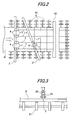
- a glass sheet G conveyed in a shape of a broad ribbon with a predetermined size in order to cut a glass sheet G conveyed in a shape of a broad ribbon with a predetermined size, groove-shaped cutting lines (refer to Fig. 3 ) in a conveying direction of the glass sheet (a longitudinal cutting line 7) and in a width direction thereof (a lateral cutting line 7') are in advance provided on an upper surface of the glass sheet by pressing a wheel chip 29 of a cutter onto a glass sheet surface.
- a bend-cutting roll 40 provided on a downstream side, the glass sheet is bent and cut off along the widthwise cutting line 7'. Thereafter, the glass sheet is bent and cut off along the lengthwise cutting line 7 in the not-shown subsequent step. In result, a glass sheet of a desired size is obtained.
- a cutting line providing apparatus 1 which provides cutting lines 7, 7' on the ribbon-shaped glass sheet G conveyed on carrying rollers 31, 31... as shown in Fig. 2 includes, as shown in Fig. 1 , a cutter 28 which provides the cutting line 7 on the surface of the glass sheet G; a ball slide device 20 which makes the cutter 28 for providing the cutting line 7 move freely up and down very smoothly with slight power so that the cutter 28 can respond to height variation in the up-down direction produced by the wave of the ribbon-shaped glass sheet G conveyed on the carrying rollers 31, 31, ..., and which absorbs an excessive pressing force during pressing the cutter 28 against the glass sheet surface, thereby to keep the pressing force contact; a spring 24 which applies an appropriate cutter pressure onto the glass sheet surface; and a pressing device 10 which presses an arm 15 that supports the ball slide device 20, the spring 24 and the cutter 28 toward the glass sheet surface.
- the cutting line providing apparatus 1 also include guides 4, each of which slides so as to freely adjust its attachment position on rails 3, 3 provided on a frame 2 provided in the direction orthogonal to a conveying direction of the ribbon-shaped glass sheet G.
- guides 4 each of which slides so as to freely adjust its attachment position on rails 3, 3 provided on a frame 2 provided in the direction orthogonal to a conveying direction of the ribbon-shaped glass sheet G.
- a desired number of the guides 4 are provided in desired positions so that the positions can be adjusted. Therefore, the lengthwise cutting lines 7, 7 are provided.
- a cutting line providing apparatus 1' is constituted so as to be able to reciprocate on a not-shown rail of a frame 2' provided so as to traverse obliquely to the glass conveying direction
- the cutting line 7' orthogonal to the conveying direction of the glass sheet is obtained. Since the cutting line providing apparatus 1' for providing the cutting line 7' runs on the rail of the frame 2' in synchronization with the conveying speed of the glass ribbon, it can provide the cutting line 7' orthogonal to the conveying direction of the glass sheet.
- the glass sheet having the longitudinal and lateral cutting lines 7' , 7 including the cutting line 7 in the conveying direction is obtained.
- a pressing cylinder 11 is hung. Near the substantially central portion of the arm 15 attached pivotally to the vicinity of the lower end of the guide 4, a leading end of a rod 12 of the pressing cylinder 11 is attached pivotally by a shaft 16.
- the arm 15 moves rotationally up and down with a shaft 5 provided at one end of the arm 15 as a rotational axis.
- a hollow bolt 17 which is inserted into a hole portion provided on the other end side of the arm 15 is fixed by nuts 18, 18'.
- a ball slide device 20 is attached and fixed through an L-shaped mounting member 19.
- the hollow bolt 17 and the L-shaped mounting member 19 are fixed to each other by a nut.
- the ball slide device 20 is composed of a rail portion 21a and an LM block 21b which has a substantially C-shaped section and can slide linearly on the rail portion. Between the rail portion 21a and the LM block 21b, a not-shown ball bearing is incorporated. Therefore, the LM block 21b can slide very smoothly on the rail portion 21a by slight power.
- the side surface of the rail portion 21a of the LM ball slide 21 is fixed through the L-shaped mounting member 19 by a not-shown bolt.
- an L-shaped spring fixing member 26 is secured by a not-shown bolt.
- a spring lower end hook 25 is screwed up.
- an L-shaped spring hanging member 22 is secured onto the side surface of the LM block 21b.
- a spring hanging hook 23 is screwed up. Between the spring hanging hook 23 and the spring lower end hook 25, a spring 24 is disposed.
- a plate-shaped cutter holder 27 supporting a cutter is secured onto the side surface of the LM block 21b.
- a cutter 28 is detachably installed at the leading end portion of the cutter holder 27, a cutter 28 is detachably installed.
- a wheel chip 29 which provides a cutting line by contact with the glass sheet is rotatably attached.
- a small tube 6 is disposed through the inside of the tubular bolt 17 and the cutter holder 27 up to the vicinity immediately above the wheel chip 29 of the cutter. Through the tube 6, the appropriate amount of cutter oil can be supplied to the wheel chip 29.
- the glass sheet G is a strip-shaped glass ribbon formed by a float method and conveyed.
- a product portion of this glass ribbon is 0.4 to 1.1 mm in thickness.
- the thickness near the end portion in the width direction of the glass ribbon is about 2 mm since the glass ribbon is formed by the float method.
- the cutting line providing apparatus described in Fig. 1 is fixedly provided for the frame 2, it can provide the cutting line 7 in the conveying direction of the glass ribbon, that is, the longitudinal cutting line. Further, in case that the cutting line providing apparatus is disposed in the oblique direction like the frame 2' in Fig. 2 and moved in synchronization with the conveying speed of the glass sheet G, it can be used as a lateral cutting machine, so that it can provide the cutting line 7' in the lateral direction.
- the rod 12 of the cylinder When the pressing cylinder 11 of the pressing device 10 is operated, the rod 12 of the cylinder extends downward, whereby the arm 15 coupled to the shaft 16 located at the leading end of the rod 12 is pressed down.
- the arm 15 moves rotationally downward with the shaft 5 as a rotation axis, the ball slide device 20 is also pressed down with the downward movement of the arm 15.
- the wheel chip 29 of the cutter 28 is pressed down toward the glass surface.
- the wheel chip 29 of the cutter 28 In case that such the pressing power that the wheel chip 29 of the cutter 28 is pressed to a position lower than the glass sheet surface is applied by the pressing device 10, the wheel chip 29 stops at the glass sheet surface. In this time, the LM block 21b moves up by the excessive pressing power, and the excessive pressing power is absorbed by the LM ball slide 21 and the spring 24. Thus, the spring 24 applies the appropriate cutter pressure.
- the wheel chip 29 of the cutter 28 rises by the rising height of the glass sheet surface.
- the LM block 21b moves up. The excessive pressing power is absorbed by the LM ball slide 21 and the spring 24 so as to prevent the wheel chip 29 of the cutter 28 from pressing the glass sheet surface excessively.
- the glass sheet is not broken even in case that the ball chip 29 is raised by the glass sheet.
- the pressure of the cutter onto the glass sheet surface is, for example, 1. 0 to 4.0 kg/cm 2 .
- the pressure is 0.5 to 1.0 kg/cm 2 which is 1/2 or less of the usual pressure; and in case of the thickness of 0.7 mm, the pressure is 0.3 to 0.8 kg/cm 2 which is 1/2 or less of the usual pressure.
- the present invention is based on Japanese Patent application No. 2007-282879, filed on October 31, 2007 , the entire contents of which are hereby incorporated by reference.
- the invention can be used in an apparatus for providing a cutting line on a glass sheet which provides a uniform cutting line without damaging the glass sheet.
Landscapes
- Chemical & Material Sciences (AREA)
- Engineering & Computer Science (AREA)
- Materials Engineering (AREA)
- Organic Chemistry (AREA)
- Mining & Mineral Resources (AREA)
- Mechanical Engineering (AREA)
- Re-Forming, After-Treatment, Cutting And Transporting Of Glass Products (AREA)
- Processing Of Stones Or Stones Resemblance Materials (AREA)
Abstract
An apparatus for providing a cutting line on a glass sheet, in which the cutting line for bend-cutting the glass sheet is provided on the glass sheet conveyed on a carrying roller, is provided with: a cutter configured to provide the cutting line on the glass sheet; a ball slide device configured to freely move the cutter up and down in accordance with an up-down movement of the conveyed glass sheet, and to absorb an excessive pressing force of the cutter onto a glass sheet surface so as to keep the pressing force constant; a spring configured to apply an appropriate cutter pressure to the glass sheet surface; an arm configured to support the ball slide device, the spring, and the cutter; and a pressing device configured to press the arm toward the glass sheet surface.
Description
- The present invention relates to an apparatus for providing a cutting line on a glass sheet which provides a uniform cutting line for cutting a broad glass ribbon formed and conveyed by a float method, particularly a thin glass sheet having a thickness of 2 mm or less, with a predetermined dimension, without damaging the glass sheet.
- A glass ribbon formed by a float method is conveyed on a conveying roll in an annealing step and an inspection step, cutting lines in required size positions in longitudinal and lateral directions are provided thereon, and then the glass ribbon is cut by bend-cutting, whereby glass sheets of the required size are obtained. However, the glass ribbon is frequently conveyed in a meandering state in a width direction, or in an up-down undulant state which is so-called wave state due to various factors received during a conveyance.
- Recently, a thin sheet glass of 2 mm or less in thickness is required as a glass sheet for display. In particular, since the glass ribbon formed into a glass sheet of 0.4 to 1.1 mm in thickness by the float method is very thin, the great wave-shaped undulation in the up-down direction is produced in the glass ribbon conveyed through the annealing step. Further, compared with a center portion of the glass ribbon used as a product, vicinities of the both end portions in the width direction thereof have the large sheet-thickness out of a standard range.
- In case that it is attempted to provide a cutting line in order to cut, in predetermined size, such the thin glass ribbon of which the product portion is 0.4 to 1.1 mm in thickness, a wheel chip of a cutter is forced on a glass sheet surface too much due to the up-down wave. Even in case that the wheel chip of the cutter is forced on the glass sheet surface too much, as long as the glass sheet has a thickness of 2 mm or more, the glass sheet is not broken. However, the thin glass ribbon of which the product portion is 0.4 to 1.1 mm in thickness can be damaged even by a small increase in pressure.
- Regarding provision of the cutting line on a glass substrate for display, many glass cutting devices which can provide a cutting line with uniform force have been proposed.
- For example, in
JP-A-2002-321933 - Further, in
JP-A-2002-274875 - Furthermore, in
JP-A-2002-316829 - Patent Document 1:
JP-A-2002-321933 - Patent Document 2:
JP-A-2002-274875 - Patent Document 3:
JP-A-2002-316829 - In the device described in the
Patent Document 1, asub-frame 14 moved up and down by amain cylinder 24 can be slid along arail 25 of amain frame 13. Thesub-frame 14 does not move freely up and down in response to unevenness of the surface of the glass sheet, but it is fixed after being set once. Further, aswing arm 31 moves up and down so as to draw an arc around a swing center axis 33 due to the unevenness of the surface of the glass sheet. Namely, theswing arm 31 is not a mechanism which can smoothly slide in a just upper direction by means of a ball bearing or the like. Therefore, the device described in thePatent Document 1 cannot necessarily follow smoothly the wave of the glass sheet. In case that a cutting line is provided on a super thin sheet glass such as a sheet glass having a thickness of 0.4 to 1.1 mm, there is fear that the super-thin sheet glass may break. - Further, in the apparatus described in the
Patent Document 2, the electric linear motor moves down the cutting line providing means to the desired position in relation to the glass sheet which gets still on a table off-line and has a little wave in the product thickness range, and a cutting line is provided on the glass sheet by an air cylinder provided for the cutting line providing means. Although the apparatus described in thePatent Document 2 can set slightly the distance between which a cutting edge is moved up and down, when it scribes the waving glass ribbon conveyed on-line, it cannot follow the glass ribbon smoothly. Therefore, in the apparatus described in thePatent Document 2, similarly to the case in the apparatus described in thePatent Document 1, in case that a cutting line is provided on a super thin sheet glass such as a sheet glass having a thickness of 0.4 to 1.1 mm, the device cannot respond to the wave and the cutting edge is forced on the glass sheet too much, so that there is fear that the glass sheet may break. - Further, in the method described in the
Patent Document 3, in relation to the glass sheet which gets still on a table off-line and has little wave in the product thickness range, a scribing head is moved up and down to the desired height by a ball screw of a Z-direction driving mechanism, and further the position of the scribing head onto the glass sheet surface can be changed by an air actuator that is a pressing mechanism, whereby the forcing pressure of the cutter head onto the glass sheet surface can be adjusted. However, in case that this method is applied to a thin sheet glass conveyed on a carrying roller, similarly to the case in the apparatuses described in thePatent Documents - One or more embodiments of the invention provides an apparatus for providing a cutting line on a thin glass sheet, in which a cutter is forced at a fixed pressure even on a glass ribbon conveyed on-line of which a central product thickness portion has a thickness of 2 mm or less, and particularly a thickness of 0.4 to 1.1 mm, thereby to prevent the glass sheet from damaging.
- According to one or more embodiment of the invention, an apparatus for providing a cutting line on a glass sheet, in which the cutting line for bend-cutting the glass sheet is provided on the glass sheet conveyed on a carrying roller, is provided with: a cutter configured to provide the cutting line on the glass sheet; a ball slide device configured to freely move the cutter up and down in accordance with an up-down movement of the conveyed glass sheet, and to absorb an excessive pressing force of the cutter onto a glass sheet surface so as to keep the pressing force constant; a spring configured to apply an appropriate cutter pressure to the glass sheet surface; an arm configured to support the ball slide device, the spring, and the cutter; and a pressing device configured to press the arm toward the glass sheet surface.
- The pressing device may be attached to a frame provided in an orthogonal direction to a conveying direction of the glass sheet so that a position of the pressing device is adjustable, and the cutting line may be provided to be in parallel to the conveying direction of the glass sheet.
- Further, the pressing device may move on a frame provided in a direction obliquely traversing a conveying direction of the glass sheet in synchronization with a conveying speed of the glass sheet, and the cutting line orthogonal to the conveying direction of the glass sheet may be provided.
- The glass sheet may be a strip-shaped glass ribbon formed and conveyed by a float method and may be a thin sheet having a thickness of 0.4 to 1.1 mm.
- In the apparatus for providing a cutting line according to the embodiment of the invention, even if a variation in the height direction of the cutter surface for providing the cutting line is occurred by a large wave of a super-thin glass ribbon conveyed on the carrying roller on-line, of which a center product portion has a thickness of 2 mm or less and particularly a thickness of 0.4 to 1.1 mm, the cutter is smoothly moved up and down by the spring and an LM ball slide without applying an excessive pressure to the glass sheet, whereby the cutting line can be provided without damaging the super thin sheet glass.
- Other aspects and advantages of the invention will be apparent from the following description, the drawings and the claims.
-
-
Fig. 1 is a side view showing one embodiment of an apparatus for providing a cutting line on a glass sheet of the invention. -
Fig. 2 is a plan view showing a relation between the apparatus for providing the cutting line and peripheral equipments thereof. -
Fig. 3 is an explanatory view showing a state where a cutting line is provided on a surface of a glass sheet by a cutter. -
- G
- Glass sheet
- 2
- Frame
- 3
- Rail
- 4
- Guide
- 5
- Shaft
- 6
- Tube
- 10
- Pressing device
- 11
- Pressing cylinder
- 12
- Rod
- 13
- Mounting member
- 15
- Arm
- 16
- Shaft
- 17
- Bolt
- 18
- Nut
- 19
- Mounting member
- 20
- Ball slide device
- 21
- LM ball slide
- 21a
- Rail portion
- 21b
- LM block
- 22
- Spring hanging member
- 23
- Spring hanging hook
- 24
- Spring
- 25
- Spring lower end hook
- 26
- Spring fixing member
- 27
- Cutter holder
- 28
- Cutter
- 29
- Wheel chip
- An exemplary embodiment of the invention will be described below with reference to drawings.
- As shown in
Fig. 2 , in order to cut a glass sheet G conveyed in a shape of a broad ribbon with a predetermined size, groove-shaped cutting lines (refer toFig. 3 ) in a conveying direction of the glass sheet (a longitudinal cutting line 7) and in a width direction thereof (a lateral cutting line 7') are in advance provided on an upper surface of the glass sheet by pressing awheel chip 29 of a cutter onto a glass sheet surface. Next, by a bend-cuttingroll 40 provided on a downstream side, the glass sheet is bent and cut off along the widthwise cutting line 7'. Thereafter, the glass sheet is bent and cut off along thelengthwise cutting line 7 in the not-shown subsequent step. In result, a glass sheet of a desired size is obtained. - In the exemplary embodiment of the invention, a cutting
line providing apparatus 1 which providescutting lines 7, 7' on the ribbon-shaped glass sheet G conveyed on carryingrollers Fig. 2 includes, as shown inFig. 1 , acutter 28 which provides thecutting line 7 on the surface of the glass sheet G; aball slide device 20 which makes thecutter 28 for providing thecutting line 7 move freely up and down very smoothly with slight power so that thecutter 28 can respond to height variation in the up-down direction produced by the wave of the ribbon-shaped glass sheet G conveyed on the carryingrollers cutter 28 against the glass sheet surface, thereby to keep the pressing force contact; aspring 24 which applies an appropriate cutter pressure onto the glass sheet surface; and apressing device 10 which presses anarm 15 that supports theball slide device 20, thespring 24 and thecutter 28 toward the glass sheet surface. - As shown in
Fig. 2 , the cuttingline providing apparatus 1 also includeguides 4, each of which slides so as to freely adjust its attachment position onrails frame 2 provided in the direction orthogonal to a conveying direction of the ribbon-shaped glass sheet G. A desired number of theguides 4 are provided in desired positions so that the positions can be adjusted. Therefore, thelengthwise cutting lines - As shown in
Fig. 2 , in case that a cutting line providing apparatus 1' is constituted so as to be able to reciprocate on a not-shown rail of a frame 2' provided so as to traverse obliquely to the glass conveying direction, the cutting line 7' orthogonal to the conveying direction of the glass sheet is obtained. Since the cutting line providing apparatus 1' for providing the cutting line 7' runs on the rail of the frame 2' in synchronization with the conveying speed of the glass ribbon, it can provide the cutting line 7' orthogonal to the conveying direction of the glass sheet. Thus, by the cuttingline providing apparatus 1 and the cutting line providing apparatus 1', the glass sheet having the longitudinal andlateral cutting lines 7' , 7 including thecutting line 7 in the conveying direction is obtained. - In the
pressing device 10, as shown inFig. 1 , from an mountingmember 13 secured extendingly from the vicinity of the upper end of theguide 4 provided for theframe 2 in the horizontal direction, apressing cylinder 11 is hung. Near the substantially central portion of thearm 15 attached pivotally to the vicinity of the lower end of theguide 4, a leading end of arod 12 of thepressing cylinder 11 is attached pivotally by ashaft 16. By extension and contraction of thepressing cylinder 11, thearm 15 moves rotationally up and down with ashaft 5 provided at one end of thearm 15 as a rotational axis. - A
hollow bolt 17 which is inserted into a hole portion provided on the other end side of thearm 15 is fixed bynuts 18, 18'. To the lower end portion of thehollow bolt 17, aball slide device 20 is attached and fixed through an L-shaped mountingmember 19. Thehollow bolt 17 and the L-shaped mountingmember 19 are fixed to each other by a nut. - The
ball slide device 20 is composed of arail portion 21a and anLM block 21b which has a substantially C-shaped section and can slide linearly on the rail portion. Between therail portion 21a and theLM block 21b, a not-shown ball bearing is incorporated. Therefore, theLM block 21b can slide very smoothly on therail portion 21a by slight power. - Further, the side surface of the
rail portion 21a of the LM ball slide 21 is fixed through the L-shaped mountingmember 19 by a not-shown bolt. Also onto the lower end side surface of therail portion 21a, an L-shapedspring fixing member 26 is secured by a not-shown bolt. Onto the upper portion of a horizontal portion of thespring fixing member 26, a springlower end hook 25 is screwed up. - On the other hand, onto the side surface of the
LM block 21b, an L-shapedspring hanging member 22 is secured. Onto the lower surface side of a horizontal tip portion of thespring hanging member 22, aspring hanging hook 23 is screwed up. Between thespring hanging hook 23 and the springlower end hook 25, aspring 24 is disposed. - Furthermore, onto the side surface of the
LM block 21b, a plate-shapedcutter holder 27 supporting a cutter is secured. At the leading end portion of thecutter holder 27, acutter 28 is detachably installed. To the lower end of thecutter 28, awheel chip 29 which provides a cutting line by contact with the glass sheet is rotatably attached. - Further, from a not-shown oil tank located on the upper side of the cutting
line providing apparatus 1, asmall tube 6 is disposed through the inside of thetubular bolt 17 and thecutter holder 27 up to the vicinity immediately above thewheel chip 29 of the cutter. Through thetube 6, the appropriate amount of cutter oil can be supplied to thewheel chip 29. - The glass sheet G is a strip-shaped glass ribbon formed by a float method and conveyed. A product portion of this glass ribbon is 0.4 to 1.1 mm in thickness. However, the thickness near the end portion in the width direction of the glass ribbon is about 2 mm since the glass ribbon is formed by the float method.
- In case that the cutting line providing apparatus described in
Fig. 1 is fixedly provided for theframe 2, it can provide thecutting line 7 in the conveying direction of the glass ribbon, that is, the longitudinal cutting line. Further, in case that the cutting line providing apparatus is disposed in the oblique direction like the frame 2' inFig. 2 and moved in synchronization with the conveying speed of the glass sheet G, it can be used as a lateral cutting machine, so that it can provide the cutting line 7' in the lateral direction. - Next, the operation of the cutting line providing apparatus of the invention will be described.
- For a continuous glass ribbon carried from a not-shown glass melting furnace through a predetermined forming step to a cutting step, of the
longitudinal cutting machines frame 2, only the desired longitudinal cutting machine is actuated in consideration of the width of a product potion which has the thickness-in-standard of the center portion of the glass ribbon. The unusedlongitudinal cutting machines pressing cylinders - When the
pressing cylinder 11 of thepressing device 10 is operated, therod 12 of the cylinder extends downward, whereby thearm 15 coupled to theshaft 16 located at the leading end of therod 12 is pressed down. When thearm 15 moves rotationally downward with theshaft 5 as a rotation axis, theball slide device 20 is also pressed down with the downward movement of thearm 15. Hereby, thewheel chip 29 of thecutter 28 is pressed down toward the glass surface. - In a state where the
wheel chip 29 of the cutter is not pressed on the glass sheet surface, by thespring 24 provided between thespring fixing member 26 fixed to therail portion 21a of the LM ball slide 21 and thespring hanging member 22 attached and fixed onto the side surface of theLM block 21b, therail portion 21a and theLM block 21b keep balance and are put in a state of balance. - In case that such the pressing power that the
wheel chip 29 of thecutter 28 is pressed to a position lower than the glass sheet surface is applied by thepressing device 10, thewheel chip 29 stops at the glass sheet surface. In this time, theLM block 21b moves up by the excessive pressing power, and the excessive pressing power is absorbed by the LM ball slide 21 and thespring 24. Thus, thespring 24 applies the appropriate cutter pressure. - Further, also in case that the glass sheet is conveyed in a state where the glass sheet surface rises by wave, the
wheel chip 29 of thecutter 28 rises by the rising height of the glass sheet surface. With rising of thewheel chip 29, theLM block 21b moves up. The excessive pressing power is absorbed by the LM ball slide 21 and thespring 24 so as to prevent thewheel chip 29 of thecutter 28 from pressing the glass sheet surface excessively. - Generally, even in case that there are rising of the glass sheet surface due to the wave and the excessive pressing power on the glass sheet surface due to the excessive pressing power by the cylinder, as long as the thickness of the glass sheet is 2 mm or more, the glass sheet is not broken even in case that the
ball chip 29 is raised by the glass sheet. - However, in case of a super-thin glass sheet having the thickness of 0.4 to 1.1 mm, when the glass sheet G is going to raise the
wheel chip 29 due to the wave, the cutter cannot frequently rise smoothly under the structure in which the excessive pressing power is absorbed by only the spring. In this case, before the cutter rises completely, the pressure between the cutter and the glass sheet surface increases, so that the glass sheet breaks. - Therefore, in the exemplary embodiment of the invention, using the LM ball slide 21 which is very small in sliding resistance due to a not-shown ball bearing together with the
elastic spring 24 enables thecutter 28 to rise smoothly in a moment, whereby the excessive pressure is not applied to the glass sheet surface for even a moment. - In case of a sheet thickness of 2 to 5 mm which is thickness of usual structural glass or of vehicle glass, the pressure of the cutter onto the glass sheet surface is, for example, 1. 0 to 4.0 kg/cm2. On the other hand, in case of a sheet thickness of 1.1 mm, the pressure is 0.5 to 1.0 kg/cm2 which is 1/2 or less of the usual pressure; and in case of the thickness of 0.7 mm, the pressure is 0.3 to 0.8 kg/cm2 which is 1/2 or less of the usual pressure.
- While the invention has been described in detail and with reference to the specific embodiment thereof, it would be apparent to those skilled in the art that various changes and modification may be made therein without departing from the scope of the invention.
- The present invention is based on Japanese Patent application No.
2007-282879, filed on October 31, 2007 - The invention can be used in an apparatus for providing a cutting line on a glass sheet which provides a uniform cutting line without damaging the glass sheet.
Claims (4)
- An apparatus for providing a cutting line on a glass sheet, in which the cutting line for bend-cutting the glass sheet is provided on the glass sheet conveyed on a carrying roller, the apparatus comprising:a cutter configured to provide the cutting line on the glass sheet;a ball slide device configured to freely move the cutter up and down in accordance with an up-down movement of the conveyed glass sheet, and to absorb an excessive pressing force of the cutter onto a glass sheet surface so as to keep the pressing force constant;a spring configured to apply an appropriate cutter pressure to the glass sheet surface;an arm configured to support the ball slide device, the spring, and the cutter; anda pressing device configured to press the arm toward the glass sheet surface.
- The apparatus for providing a cutting line on a glass sheet according to Claim 1, wherein the pressing device is attached to a frame provided in an orthogonal direction to a conveying direction of the glass sheet so that a position of the pressing device is adjustable, and the cutting line is provided to be in parallel to the conveying direction of the glass sheet.
- The apparatus for providing a cutting line on a glass sheet according to Claim 1, wherein the pressing device is moved on a frame provided in a direction obliquely traversing a conveying direction of the glass sheet in synchronization with a conveying speed of the glass sheet, and the cutting line orthogonal to the conveying direction of the glass sheet is provided.
- The apparatus for providing a cutting line on a glass sheet according to any of Claims 1 to 3, wherein the glass sheet is a strip-shaped glass ribbon formed and conveyed by a float method and is a thin sheet having a thickness of 0.4 to 1.1 mm.
Applications Claiming Priority (2)
| Application Number | Priority Date | Filing Date | Title |
|---|---|---|---|
| JP2007282879A JP5311796B2 (en) | 2007-10-31 | 2007-10-31 | Equipment for applying scoring lines to glass plates |
| PCT/JP2008/068967 WO2009057474A1 (en) | 2007-10-31 | 2008-10-20 | Device for scoring glass sheet |
Publications (2)
| Publication Number | Publication Date |
|---|---|
| EP2213632A1 true EP2213632A1 (en) | 2010-08-04 |
| EP2213632A4 EP2213632A4 (en) | 2011-03-30 |
Family
ID=40590866
Family Applications (1)
| Application Number | Title | Priority Date | Filing Date |
|---|---|---|---|
| EP08844121A Withdrawn EP2213632A4 (en) | 2007-10-31 | 2008-10-20 | Device for scoring glass sheet |
Country Status (6)
| Country | Link |
|---|---|
| US (1) | US20100242702A1 (en) |
| EP (1) | EP2213632A4 (en) |
| JP (1) | JP5311796B2 (en) |
| KR (1) | KR20100092429A (en) |
| CN (1) | CN101842326B (en) |
| WO (1) | WO2009057474A1 (en) |
Cited By (3)
| Publication number | Priority date | Publication date | Assignee | Title |
|---|---|---|---|---|
| EP2352163A3 (en) * | 2010-01-27 | 2011-12-28 | Mitsuboshi Diamond Industrial Co., Ltd. | Scribing apparatus for thin film solar cells |
| WO2014159168A1 (en) * | 2013-03-14 | 2014-10-02 | Corning Incorporated | Methods for fabricating and cutting flexible glass and polymer composite structures and apparatus |
| WO2021126542A1 (en) * | 2019-12-16 | 2021-06-24 | Corning Incorporated | Reciprocating score device |
Families Citing this family (16)
| Publication number | Priority date | Publication date | Assignee | Title |
|---|---|---|---|---|
| KR101048068B1 (en) | 2009-06-26 | 2011-07-11 | 세메스 주식회사 | Scribing head and substrate cutting device including same |
| JP5387915B2 (en) * | 2009-12-28 | 2014-01-15 | 旭硝子株式会社 | Cutter traveling control method and sheet glass cutting method |
| CN102167504B (en) * | 2009-12-28 | 2015-09-30 | 旭硝子株式会社 | The cutting-off method of advance control method and the sheet glass of cutter |
| JP5331187B2 (en) * | 2011-11-10 | 2013-10-30 | 古河電気工業株式会社 | Thin glass manufacturing method and glass substrate manufacturing method |
| TWI586612B (en) * | 2011-11-18 | 2017-06-11 | 康寧公司 | Apparatus and method for trimming a moving glass ribbon |
| JP2013163626A (en) * | 2012-02-13 | 2013-08-22 | Asahi Glass Co Ltd | Cut line processing apparatus for plate-shaped substance and cut line processing method for plate-shaped substance, and manufacturing apparatus for glass sheet and manufacturing method for glass sheet |
| DE102012025091B4 (en) * | 2012-12-20 | 2016-09-29 | Grenzebach Maschinenbau Gmbh | Apparatus and method for producing a safe breaking line for the industrial cutting to length of glass panes and computer program and machine-readable carrier with a program code |
| CN105848841B (en) * | 2013-12-27 | 2017-07-28 | 旭硝子株式会社 | Processing method of brittle plate and processing device of brittle plate |
| CN104714480A (en) * | 2015-01-08 | 2015-06-17 | 中意凯盛(蚌埠)玻璃冷端机械有限公司 | Automatic correcting system for plate length cutting errors of glass transverse cutting machine |
| CN106277739B (en) * | 2016-08-05 | 2019-03-22 | 湖北新华光信息材料有限公司 | Optical glass plate automatically under disconnected device |
| CN106865973A (en) * | 2017-03-09 | 2017-06-20 | 东旭科技集团有限公司 | Glass manufacturing apparatus and glass production line |
| WO2019055751A1 (en) | 2017-09-15 | 2019-03-21 | Corning Incorporated | Systems and methods for processing a glass ribbon |
| TW202023780A (en) * | 2018-11-27 | 2020-07-01 | 日商三星鑽石工業股份有限公司 | Pressure measurement mechanism and breaking device provided with said pressure measurement mechanism |
| CN113954253B (en) * | 2021-10-29 | 2022-09-13 | 九江润诚新材料有限公司 | Special glass's cutting assembly |
| CN113929292B (en) * | 2021-11-22 | 2024-03-22 | 安徽信义智能机械有限公司 | Glass connecting line corner transverse cutting conveyor and using method thereof |
| CN117067409B (en) * | 2023-08-30 | 2025-09-19 | 泰山石膏(江西)有限公司 | Gypsum board cutting machine |
Family Cites Families (19)
| Publication number | Priority date | Publication date | Assignee | Title |
|---|---|---|---|---|
| US3122953A (en) * | 1964-03-03 | Apparatus and method of cutting glass | ||
| US4210052A (en) * | 1977-05-09 | 1980-07-01 | Libbey-Owens-Ford Company | Scoring mechanism |
| CA1077823A (en) * | 1977-08-10 | 1980-05-20 | Brian Hargreaves | Apparatus for cutting or scoring sheet material |
| US4291824A (en) * | 1978-01-26 | 1981-09-29 | Ppg Industries, Inc. | Self-aligning method for scoring fracturable material |
| US5038654A (en) * | 1989-04-04 | 1991-08-13 | Ppg Industries, Inc. | Apparatus for scoring a glass sheet |
| EP0642402A4 (en) * | 1992-05-18 | 1995-09-27 | Lockformer Co | Glass scoring mechanism. |
| JP3968789B2 (en) * | 1994-02-16 | 2007-08-29 | 坂東機工株式会社 | Cutter device |
| US6536121B1 (en) * | 1999-08-06 | 2003-03-25 | Thk Co., Ltd. | Scribing apparatus |
| JP4705713B2 (en) * | 2000-09-08 | 2011-06-22 | 中村留精密工業株式会社 | Hard brittle board scribing device |
| JP5065551B2 (en) | 2001-01-12 | 2012-11-07 | 坂東機工株式会社 | Glass plate cutting head and glass plate processing apparatus having the same |
| JP2002316829A (en) * | 2001-04-17 | 2002-10-31 | Seiko Epson Corp | Glass substrate cutting method, electro-optical device manufacturing method, electro-optical device, electronic device, and scribe groove forming device |
| JP2002321933A (en) * | 2001-04-27 | 2002-11-08 | Kawasaki Heavy Ind Ltd | Cutting line cutting equipment for sheet glass |
| JP4149742B2 (en) * | 2002-06-10 | 2008-09-17 | 中村留精密工業株式会社 | Hard brittle plate cutting device |
| JP4142458B2 (en) * | 2003-01-20 | 2008-09-03 | 中村留精密工業株式会社 | Vibration scribing method and apparatus for hard brittle plate |
| KR101365376B1 (en) * | 2005-03-23 | 2014-02-19 | 티에치케이 가부시끼가이샤 | Scribe device |
| DE102006012582B4 (en) * | 2006-03-16 | 2010-01-21 | Schott Ag | Apparatus and method for separating sections of glass rods |
| JP2007282879A (en) | 2006-04-18 | 2007-11-01 | Keakomu:Kk | Nurse call system and information recording method |
| WO2008126502A1 (en) * | 2007-03-30 | 2008-10-23 | Thk Co., Ltd. | Scribe device and scribe method |
| JP5508847B2 (en) * | 2007-04-12 | 2014-06-04 | 三星ダイヤモンド工業株式会社 | Scribing apparatus and method |
-
2007
- 2007-10-31 JP JP2007282879A patent/JP5311796B2/en not_active Expired - Fee Related
-
2008
- 2008-10-20 US US12/740,012 patent/US20100242702A1/en not_active Abandoned
- 2008-10-20 KR KR1020107009064A patent/KR20100092429A/en not_active Ceased
- 2008-10-20 CN CN2008801143912A patent/CN101842326B/en not_active Expired - Fee Related
- 2008-10-20 WO PCT/JP2008/068967 patent/WO2009057474A1/en not_active Ceased
- 2008-10-20 EP EP08844121A patent/EP2213632A4/en not_active Withdrawn
Cited By (4)
| Publication number | Priority date | Publication date | Assignee | Title |
|---|---|---|---|---|
| EP2352163A3 (en) * | 2010-01-27 | 2011-12-28 | Mitsuboshi Diamond Industrial Co., Ltd. | Scribing apparatus for thin film solar cells |
| WO2014159168A1 (en) * | 2013-03-14 | 2014-10-02 | Corning Incorporated | Methods for fabricating and cutting flexible glass and polymer composite structures and apparatus |
| US11766849B2 (en) | 2013-03-14 | 2023-09-26 | Corning Incorporated | Methods and apparatus for fabricating and cutting flexible glass and polymer composite structures |
| WO2021126542A1 (en) * | 2019-12-16 | 2021-06-24 | Corning Incorporated | Reciprocating score device |
Also Published As
| Publication number | Publication date |
|---|---|
| US20100242702A1 (en) | 2010-09-30 |
| KR20100092429A (en) | 2010-08-20 |
| JP5311796B2 (en) | 2013-10-09 |
| CN101842326B (en) | 2012-10-03 |
| JP2009107897A (en) | 2009-05-21 |
| EP2213632A4 (en) | 2011-03-30 |
| CN101842326A (en) | 2010-09-22 |
| WO2009057474A1 (en) | 2009-05-07 |
Similar Documents
| Publication | Publication Date | Title |
|---|---|---|
| EP2213632A1 (en) | Device for scoring glass sheet | |
| EP2275215B1 (en) | Long-material conveying and positioning apparatus | |
| CN105793204B (en) | Glass plate manufacturing apparatus and method | |
| KR101574616B1 (en) | Glass plate scribing method and scribing apparatus | |
| JP5568051B2 (en) | How to split a glass sheet from a continuous glass ribbon | |
| JP3194224U (en) | Panel splitting device | |
| CN203653429U (en) | Breaking device for thin glass materials | |
| CN211493344U (en) | Digital printing machine | |
| CN102099306A (en) | Cutting line processing device for glass ribbon and cutting line processing method for glass ribbon | |
| CN110576474A (en) | A pearl cotton horizontal and vertical slitting machine | |
| KR20190094597A (en) | Connecting film cutting apparatus for windows glasses of vehicles | |
| KR20150093199A (en) | Device for glass sheet flattening and method of flattening a sheet of glass | |
| JP4027700B2 (en) | Scribe and break device | |
| CN111362567A (en) | An edge breaking device and glass cold end equipment | |
| CN1958488B (en) | Apparatus for substrate marking | |
| CN113198903B (en) | Blanking machine for processing metal plate | |
| JP2012131706A (en) | Cutting line processing device for sheet glass and cutting line processing method thereof | |
| CN102126826B (en) | Cutting line processing device and cutting line processing method for flat glass | |
| JP2014193526A (en) | Peeling device for protective film of smc sheet | |
| KR20210001788U (en) | Glass sheet manufacturing apparatus | |
| CN221269856U (en) | Plate sawing machine | |
| KR102571055B1 (en) | Scribing method and scribing apparatus | |
| KR101756072B1 (en) | Apparatus and method of breaking a non-metalic material by using a roller | |
| KR20230118452A (en) | Apparatus for forming double-curvature plate | |
| CN214827774U (en) | Novel sheet machine |
Legal Events
| Date | Code | Title | Description |
|---|---|---|---|
| PUAI | Public reference made under article 153(3) epc to a published international application that has entered the european phase |
Free format text: ORIGINAL CODE: 0009012 |
|
| 17P | Request for examination filed |
Effective date: 20100421 |
|
| AK | Designated contracting states |
Kind code of ref document: A1 Designated state(s): AT BE BG CH CY CZ DE DK EE ES FI FR GB GR HR HU IE IS IT LI LT LU LV MC MT NL NO PL PT RO SE SI SK TR |
|
| AX | Request for extension of the european patent |
Extension state: AL BA MK RS |
|
| DAX | Request for extension of the european patent (deleted) | ||
| A4 | Supplementary search report drawn up and despatched |
Effective date: 20110302 |
|
| STAA | Information on the status of an ep patent application or granted ep patent |
Free format text: STATUS: THE APPLICATION HAS BEEN WITHDRAWN |
|
| 18W | Application withdrawn |
Effective date: 20110823 |