EP2211185A1 - Inertial sensor unit or resonant sensor with surface technology, with out-of-plane detection by strain gauge - Google Patents
Inertial sensor unit or resonant sensor with surface technology, with out-of-plane detection by strain gauge Download PDFInfo
- Publication number
- EP2211185A1 EP2211185A1 EP10151288A EP10151288A EP2211185A1 EP 2211185 A1 EP2211185 A1 EP 2211185A1 EP 10151288 A EP10151288 A EP 10151288A EP 10151288 A EP10151288 A EP 10151288A EP 2211185 A1 EP2211185 A1 EP 2211185A1
- Authority
- EP
- European Patent Office
- Prior art keywords
- plane
- zone
- mass
- substrate
- axis
- Prior art date
- Legal status (The legal status is an assumption and is not a legal conclusion. Google has not performed a legal analysis and makes no representation as to the accuracy of the status listed.)
- Granted
Links
Images


Classifications
-
- G—PHYSICS
- G01—MEASURING; TESTING
- G01P—MEASURING LINEAR OR ANGULAR SPEED, ACCELERATION, DECELERATION, OR SHOCK; INDICATING PRESENCE, ABSENCE, OR DIRECTION, OF MOVEMENT
- G01P15/00—Measuring acceleration; Measuring deceleration; Measuring shock, i.e. sudden change of acceleration
- G01P15/02—Measuring acceleration; Measuring deceleration; Measuring shock, i.e. sudden change of acceleration by making use of inertia forces using solid seismic masses
- G01P15/08—Measuring acceleration; Measuring deceleration; Measuring shock, i.e. sudden change of acceleration by making use of inertia forces using solid seismic masses with conversion into electric or magnetic values
- G01P15/097—Measuring acceleration; Measuring deceleration; Measuring shock, i.e. sudden change of acceleration by making use of inertia forces using solid seismic masses with conversion into electric or magnetic values by vibratory elements
-
- G—PHYSICS
- G01—MEASURING; TESTING
- G01C—MEASURING DISTANCES, LEVELS OR BEARINGS; SURVEYING; NAVIGATION; GYROSCOPIC INSTRUMENTS; PHOTOGRAMMETRY OR VIDEOGRAMMETRY
- G01C19/00—Gyroscopes; Turn-sensitive devices using vibrating masses; Turn-sensitive devices without moving masses; Measuring angular rate using gyroscopic effects
- G01C19/56—Turn-sensitive devices using vibrating masses, e.g. vibratory angular rate sensors based on Coriolis forces
- G01C19/5642—Turn-sensitive devices using vibrating masses, e.g. vibratory angular rate sensors based on Coriolis forces using vibrating bars or beams
- G01C19/5656—Turn-sensitive devices using vibrating masses, e.g. vibratory angular rate sensors based on Coriolis forces using vibrating bars or beams the devices involving a micromechanical structure
-
- G—PHYSICS
- G01—MEASURING; TESTING
- G01C—MEASURING DISTANCES, LEVELS OR BEARINGS; SURVEYING; NAVIGATION; GYROSCOPIC INSTRUMENTS; PHOTOGRAMMETRY OR VIDEOGRAMMETRY
- G01C19/00—Gyroscopes; Turn-sensitive devices using vibrating masses; Turn-sensitive devices without moving masses; Measuring angular rate using gyroscopic effects
- G01C19/56—Turn-sensitive devices using vibrating masses, e.g. vibratory angular rate sensors based on Coriolis forces
- G01C19/5719—Turn-sensitive devices using vibrating masses, e.g. vibratory angular rate sensors based on Coriolis forces using planar vibrating masses driven in a translation vibration along an axis
- G01C19/5769—Manufacturing; Mounting; Housings
-
- G—PHYSICS
- G01—MEASURING; TESTING
- G01P—MEASURING LINEAR OR ANGULAR SPEED, ACCELERATION, DECELERATION, OR SHOCK; INDICATING PRESENCE, ABSENCE, OR DIRECTION, OF MOVEMENT
- G01P15/00—Measuring acceleration; Measuring deceleration; Measuring shock, i.e. sudden change of acceleration
- G01P15/02—Measuring acceleration; Measuring deceleration; Measuring shock, i.e. sudden change of acceleration by making use of inertia forces using solid seismic masses
- G01P15/08—Measuring acceleration; Measuring deceleration; Measuring shock, i.e. sudden change of acceleration by making use of inertia forces using solid seismic masses with conversion into electric or magnetic values
- G01P15/0802—Details
Definitions
- the invention relates to the field of micro-sensors, in particular silicon, for example inertial sensors, including accelerometers.
- Inertial sensors made in volume technology are based on off-plane electrostatic excitation of the resonator. They are of large size.
- the detection resonator is thinned with respect to the substrate, and therefore has a thickness different from the moving mass.
- This thinning which is very poorly controlled, is, among other things, made necessary by the vibration mode of the beam which is off plan.
- the resonator is placed on the surface of the substrate.
- the resonator should be as close as possible to the hinge (axis of rotation of the mass).
- the invention proposes a new type of sensor, made in planar technology, for detecting an out-of-plane force applied to a released mechanical mass, and implementing detection by one or more suspended gauges, for example of the piezoresistive or resonator type ( beam or tuning fork).
- This sensor according to the invention makes it possible, inter alia, to carry out an accelerometer or a mass sensor. It allows in particular a detection by gauge piezoresistive but other types of detection are possible.
- This sensor makes it possible to separately optimize the shapes, materials and thicknesses of the moving part (inertial mass) and of the gauge used for the detection and measurement of the stress.
- Such a positioning of the third zone makes it possible to have a thickness of the pivot zone that is independent of the thickness of the third zone and also makes it possible to preferentially obtain the point (s) of application of the stresses imposed by the first zone on the third zone is in line with the pivot axis H, that is to say in a plane perpendicular to N1 and / or N2 containing the pivot axis H. This allows to increase the arm of lever of the seismic mass on the strain gages.
- the second zone has, in a direction perpendicular to the plane of the substrate, a lower part and an upper part, one of these two parts being in the first plane or in the second plane of the first zone, which is therefore called common plane in the first and second zones.
- the upper part of the second zone is located in the first plane (or upper plane) of the first zone and / or the lower zone of the second zone is located in the second plane (or lower plane) of the first zone.
- the third zone has, in a direction perpendicular to the plane of the substrate, a lower part and an upper part, one of these two parts that can be in the plane common to the first and second zones.
- the thickness of the second zone (pivoting) is independent of the thickness of the third zone.
- the difference in thickness between the third zone and the second zone makes it possible to have a stress in tension or in compression: if these two zones were of the same thickness, one could not have access independently to these constraints. In the case of detection by piezoelectric effect, it would then be canceled.
- the point (s) of application of stresses imposed by the first zone on the third zone is in line with the pivot axis H, that is to say in a plane perpendicular to the foreground and / or in the second plane of the first zone and containing the pivot axis H.
- This makes it possible to increase the lever arm of the seismic mass on the strain gages.
- the first and second zones may be formed in one or more semiconductor and / or insulating materials.
- the first and the second zone may be in identical or different materials.
- MEMS sensor sensors comprising micronic and / or sub-micronic elements.
- the second zone forming a pivot connection for the moving mass, allows only a rotational movement of the latter around the pivot axis, preventing any further movement of the moving mass.
- the second zone may comprise several segments aligned along the pivot axis.
- the moving mass may have a thickness strictly greater than that of the second zone (forming a pivot).
- the latter itself has a thickness strictly greater than that of the third zone, comprising the strain gauge or gauges, advantageously greater than twice the thickness of the third zone.
- the strain gauge (s) and the moving mass may have a common plane, which may be the lower plane of the mass.
- the gauges and the moving mass are then located on the same side with respect to this plane. Alternatively they may have as a common plane the upper plane of the mass. The gauges are then located on one side of this plane and the moving mass on the other side.
- the axis of the pivot connection is in a plane passing through the center of gravity G of the moving mass. This plan is parallel to the foreground and the background.
- the strain gauge (s) may be of piezoresistive material such as monocrystalline or polycrystalline silicon or SiGe, or nanowires, for example silicon, or nanotubes, for example carbon. It can then be used as a suspended gauge, whose electrical resistance variation is then measured as a function of the stress exerted on it.
- the gauge can be performed by etching in a semiconductor substrate.
- it can be produced by depositing a piezoresistive material such as polycrystalline silicon, silicon nano-wires or carbon nanotubes.
- the gauge may be in a material, such as a metal, for which the deformation modifies the resistance, by geometric effects.
- Nanowires in particular silicon nanowires, are elongated structures in one direction, this direction being called length.
- the transverse dimensions in a section perpendicular to this direction are much smaller than this length. These transverse dimensions are typically less than 100 nm, preferably less than 50 nm or 40 nm and advantageously less than 20 nm.
- Nanowires oriented in a direction X, contained in the plane of a substrate can be obtained by etching a silicon beam in transverse Y and Z directions, or by growth of a nanowire, for example by catalyzed SLV deposition.
- the gauge (s) may be of the single branch type or the double branch type.
- the gauge for example variable resistance
- the gauge may be of the single branch type, a current may for example enter through the gauge and out through one of the pivot areas or vice versa.
- the gauge may be of the double branch type, a current can enter through one of the branches and out another.
- the two branches may be parallel to each other, an electrical insulation being preferably provided between the gauge and the first zone.
- the strain gauge (s) may comprise a vibration detection resonator in the plane of the substrate, comprising at least one vibrating plate, an excitation means and a means for detecting the vibration.
- the strain gauge can therefore be a detection resonator, for example of the beam or tuning fork type, which is then measured for the variation of frequency according to the stress exerted on it.
- the vibration of the gauge in the plane of the substrate can be done by electrostatic means.
- the detection resonator is excited at resonance.
- the variation of the vibration frequency of the detection resonator is a function of the stress exerted by the mass.
- the excitation of the vibrating blade and / or the detection of the resonance can then be done by electrostatic means by means of at least one electrode arranged, with respect to the vibrating blade, in the direction of vibration.
- the detection of the resonance can also be done by means of piezoresistive means arranged on the vibrating blade.
- the vibrations can therefore be measured by electrodes arranged in the plane of the sensor.
- the gauge is excited by electrostatic means, and the measured stresses, by piezoelectric means disposed on the resonator.
- a sensor according to the invention may be an accelerometer-type sensor, the stress applied by the mass being due to the inertia of the mass during a displacement of the entire sensor.
- an acceleration outside the plane of the sensor will rotate the first zone, which forms mobile mass, by an angle ⁇ around the axis of the pivot connection of the second zone.
- This rotation of the moving mass will exert a constraint on the strain gauge.
- this constraint induces a variation of its frequency and / or the amplitude of vibration.
- this constraint induces a variation of its electrical resistance, proportional to the stress exerted. It is then possible to calculate the acceleration.
- the pivot axis and the central axis of the gauge are in two different planes, parallel to the plane of the sensor or the substrate in which it is made.
- the stress on the gauge is amplified by the lever arm formed between the center of gravity G of the moving mass, where the force due to the acceleration, the pivot axis and the point of application of the stress apply. the gauge. The more this point of application is close to the pivot axis H, but not on this axis, the greater the measured stress is important.
- the point of application of the stress on the gauge is preferably located vertically above the pivot axis. More preferably, the pivot axis is located in the same plane, parallel to that of the sensor, the center of gravity of the mobile mass.
- a variation in voltage or current imposed on the vibrating means leads to a local deformation of the mass and therefore to a setting in motion. This movement becomes a vibration if the pulse given by the vibrating zone is due to, for example, the pulse of an alternating current.
- the invention therefore also relates to a resonator-type chemical mass sensor comprising a device according to the invention provided with means for vibrating the mobile mass.
- the vibrating moving mass can then be referred to as the "vibrating beam”.
- the vibrating beam may further comprise at its surface means for selecting molecules or a type or several types of molecules or families of molecules that can be adsorbed or absorbed on the surface, for example by means of radicals of given molecules or a layer of material sensitive to a single type of molecule.
- the surface of the vibrating beam may be covered by a material that reacts in a particular way to a chemical and / or biochemical element and / or has attachment molecules that are specific to a molecule or a family of molecules.
- the vibrating beam sees its mass increase as and when molecules are adsorbed.
- the vibration frequency of the vibrating beam then varies and the stresses applied to the strain gauges are modified.
- Such a device can be used to detect the presence and / or concentration of one or more molecules in a medium.
- An advantage of this device compared to a chemical mass sensor whose axis of displacement of the vibrating beam is in the plane, is as follows.
- the mobile mass is advantageously in a gaseous environment or in a vacuum.
- the moving mass, or vibrating beam is brought into contact with the carrier fluid.
- a strain gauge of the detection resonator type when it is, is advantageously in a medium close to vacuum. In fact, an attenuation due to a gaseous medium would have the effect of degrading the quality factor of the resonator and thus of decreasing the resolution of the sensor.
- a device according to the invention will preferably have a variable resistance strain gauge, for example of the piezoresistive type.
- all the electrical connections can be done by integration on the front face of the substrate, before and / or after forming the device according to the invention.
- the three zones may be formed by etching a layer of semiconductor material, etching the sacrificial layer to release the mobile element of the sensor.
- They can in particular be formed by etching a surface layer of semiconductor material of an SOI substrate, the SOI oxide layer serving as a sacrificial layer and electrical insulator for the fixed parts.
- the thin zone may be formed in a surface layer deposited on the semiconductor substrate, the first two zones formed by etching a layer of semiconductor material, etching the sacrificial layer to release the mobile element of the sensor. .
- the second zone may be of thickness between that of the first zone and that of the third zone.
- the second zone may be of thickness equal to that of the first zone.
- This method makes it possible to produce a device according to the invention, as described above.
- the other characteristics of a device according to the invention therefore apply to a method according to the invention.
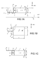
- a sensor according to the invention is included or made in a substrate or wafer 2, for example of semiconductor material, for example of monocrystalline or polycrystalline silicon or in a SiGe layer, deposited on a silicon substrate or in a glass type material.
- This plate has an upper face 21 (or first face) and a lower face 22 (or second face).
- These numerical references are represented on the Figure 1A as an example but will eventually be recalled in other figures.
- These two faces 21 and 22 are parallel to each other and each is located in a plane N21, N22 (which may be called the upper plane N21 and the lower plane N22, or the first plane of the plate N21 and the second plane of the plate N22 ).
- the senor, or its moving mass 3, included in the wafer 2 also comprises an upper face 11 (or first face) and a lower face 12 (or second face), the upper face 11 of the sensor being in a plane N1 which may be identical to the plane N21 of the upper face 21 of the wafer.
- the lower face 12 of the sensor is in a plane N2, different from the lower plane of the wafer N22.
- N2 is between the upper planes N1 / N21 and the lower plane of the wafer N22.
- face or plane without mention of wafer, correspond to the planes and faces of the sensor: N1 and N2.
- the adjectives "inferior” and “superior” are chosen as a convenience, but do not express a definitive relative position of one plane relative to the other.
- the terms “first face” and “second face” can also be used respectively.
- the so-called lower face of the mass 3 faces, and is parallel to, a face 22 'of the substrate updated by etching during the implementation of a method for producing the device according to the invention. This face 22 'is for example included in a plane N22' between N2 and N22.
- An orthonormal coordinate system comprising two mutually perpendicular axes, X and Y, located in one of the N planes defined above, the third axis, Z, being the axis perpendicular to the planes NOT.
- An accelerometric device comprises a mass 3 of a first thickness T, measured in the direction Z perpendicular to the faces or the plane of the wafer (as well as the thicknesses mentioned later in this text).
- the plans of this mass parallel to the plane N of the wafer define the first plane N1 and second plane N2 of the sensor.
- This mass 3 forms a mobile mass. It may be of the same material as the substrate 2. It is for example monocrystalline or polycrystalline silicon or SiGe, or a glass-type material.
- the thickness T of the mass 3 is for example between about 500 nm and some 10 microns, for example 1 micron.
- the mass 3 may have a length L, measured along the Y axis of the XY plane, of between a few micrometers and a few hundreds of ⁇ m, for example between 10 ⁇ m or 50 ⁇ m and 100 ⁇ m or 200 ⁇ m or 500 ⁇ m, and a width l, measured along the X axis of the XY plane, which may be between a few ⁇ m and a few hundreds of ⁇ m, for example between 10 ⁇ m or 50 ⁇ m and 100 ⁇ m or 200 ⁇ m or 500 ⁇ m.
- This mobile mass is connected to a second zone 5, of second thickness, which thus forms a pivot connection, also called a hinge, of axis H parallel to the planes N defined above (this axis H is perpendicular to the plane of the Figure 1A ).
- the axis H is disposed between the first plane (N1) and the second plane (N2) of the mass 3, and parallel to each of them.
- the X axis of the reference frame linked to the substrate can be chosen as being the direction of the axis H of rotation.
- Z is perpendicular to each of the planes N. It is therefore sufficient to choose the direction Y perpendicular to the directions X and Z to completely define the orthonormal frame.
- the pivot zone comprises an upper portion and a lower portion disposed at different altitudes along the Z axis. It lies between the two planes N1 and N2 which respectively encompass the upper face and the lower face of the mass 3. If its lower part is in the plane N2, the plane N2 is said plane common to the first and second parts. In addition, or alternatively, the upper part of the pivot zone may be in the plane N1, and the plane N1 is then said plane common to the first and second parts. In the embodiment of the Figure 1A , the upper part and the lower part of the pivot zone are respectively in the plane N1 and in the plane N2, these two planes N1 and N2 are therefore common to the first and second parts.
- the geometry and / or the dimensions of the pivot zone are such that the axis of rotation H is in a plane parallel to the planes N passing through the center of gravity G of the mobile mass. This reduces the sensitivity to transverse accelerations. This particular position of the axis of rotation is obtained especially when the thicknesses of the first and second zones are equal in the Z direction.
- the moving mass 3 can rotate J about the pivot axis and can not perform any other movement in the orthonormal frame XYZ bound to the substrate, and in particular no rotation around another axis.
- this effect blocking the other rotations is obtained in that the pivot zone or hinge is composed of two parts 5 and 5 'aligned along the axis H.
- the hinge zone can be in one piece, sufficiently wide in the direction X to limit the rotations of the mass along the other axes.
- the movement allowed to the moving mass 3 is therefore a movement J out of the plane of the sensor.
- the hinge zone 5 is connected to the moving mass 3 and to a fixed zone 50 of the device. It has for example a connection of the embedding type with the substrate in which the device is formed.
- a movement of the moving mass causes a deformation of the second zone (pivot zone) and not a deformation of the entire moving mass.
- a third zone 4 forms at least one suspended strain gauge with a thickness e which is smaller than that of the moving mass T. It forms a means of detecting the movement of the moving mass 3.
- the thickness e of the gauge (s) is between, on the one hand, 10 nm or a few tens of nm (for example 40 nm for a strain gauge of the nanowire type or 200 nm for a suspended strain gage in polycrystalline silicon), and, on the other hand, a few micrometers, for example 1 micron or 5 microns or 10 microns.
- a so-called "suspended" type gauge is held between two so-called end portions.
- the portion of the gauge, said central portion, disposed between these two end portions is of non-zero length and is in contact with no other material, and in particular none of the materials of the sensor component.
- such a gauge is of elongate shape in a direction, and of length, so-called length of the gauge, very large in this direction in front of each dimension measured in a section perpendicular to said direction. It is maintained in two end portions, each of which is of small or very small length in front of the length of the gauge or of its central portion.
- This strain gauge 4 extends in a plane which is parallel to the plane of the sensor but which does not contain the axis H of rotation of the pivot connection, as it appears on FIG. Figure 1A . This remains true in the embodiments of the Figures 9A-9D . It is in contact at one of its ends with the mobile mass, at its other end to the substrate which holds it fixed. These two contact points may be, for example, embedded links.
- This strain gauge 4 is arranged between two planes, or comprises a lower portion and an upper portion positioned at different altitudes in a direction perpendicular to that of the substrate. One of these planes, or one of these parts, is one of the planes N1, N2, or is contained in one of these planes, and preferably the plane common to the first and second areas. In this case, the gauge is said to be aligned with the upper or lower part of the second zone and the moving mass 3 (when the latter is at rest).
- the second zone and the third zone each have a width, along the X axis, smaller than that of the mass 3 also measured along X.
- the sum of these widths of the third and second zones is smaller than that of the mass. This is particularly the case when the gauge has a plane in the common plane of the first and second zones. But this can also be the case for any embodiment of the invention, regardless of the position of the gauge and the second zone.
- This third zone is advantageously made of a piezoresistive material, for example made of monocrystalline or polycrystalline silicon, or it is composed of carbon nanotubes, or nano-wires of silicon, or of metal, etc.
- strain gauge as shown below, can be a detection resonator.
- a rotation J of the moving mass around the pivot connection Z is translated by the application of a F force exerted on the strain gauge (s) 4.
- the point of application P of the stress on the gauge 4 is advantageously in a plane containing the axis H of the pivot connection and perpendicular to the plane of the substrate or to each of the upper planes N2 and lower N1. This point of application is then said "in line" with the axis H of rotation of the pivot connection 5, which makes it possible to have, at first order, only an axial stress on the gauge.
- the direction of the strain gauge 4 is normal to the plane containing the axis H which is itself perpendicular to the plane of the device.
- a first embodiment of the invention relates to an accelerometer type device ( Figures 1A to 1G ). Variants will be described, a first in connection with the Figures 1A, 1B , a second in connection with the Figures 1C , 1D , a third and a fourth in connection with the Figures 1E, 1F , a fifth variation of strain gauge is presented in figure 1G . Other variants are described later with the Figures 9A - 9D .
- the gauge is disposed below the torsion axis H. That is to say, there is a common plane between the moving mass, the second zone (5, 5 ') and the dipstick. constraint 4, this common plane is the lower plane N2 of the mobile mass comprising the lower face 12 of the mass 3; we can say that the gauge is placed in the lower plane of the moving mass 3 in the configuration shown.
- the gauge is advantageously formed by etching. The gauge and the moving mass are located on the same side of the common plane N2.
- the gauge (s) 6 is (are) disposed above the torsion axis H.
- the gauge (s) 6 is (are) formed ( s) by deposit.
- the gauges 6 and the moving mass 3 are, in this variant, located on either side of this plane which is common to them (the latter contains the lower part of the gauges 6 and the upper part 11 of the mass).
- the zone 5 forming a pivot has a thickness close to that of the mass 3.
- the zone 5 has the same thickness as the moving mass 3.
- the pivot axis H is then in the same plane, parallel to the plane of the substrate 2 , that the center of gravity G of the moving mass 3.
- the zone 5 then has two planes, parallel to the plane of the substrate 2, in common with the mobile mass 3. These are the planes N1 and N2. This remains true in the embodiments of the Figures 9A-9D .
- the pivot zone 5 then has its lower part in the lower plane N2 of the sensor, containing the rear face 12 of the mass 3 (their common plane is the plane N2, but not the plane N1).
- the pivot zone whose thickness is thinner than the moving mass, is thus positioned close to the lower part of the moving mass 3.
- the axis H can then also be closer to this lower part of the mass 3. This situation slightly modifies the force imposed on the strain gauge 4, and thus the value and precision of the measurements.
- the low position of the axis of rotation H has the effect of increasing the stress on a gauge 4 located closer to the pivot axis H, in the lower plane N2 (case of the figure 1F ).
- the gauge then has a lower part in the lower plane N2 of the mass 3. This plane N2 is here common to the three zones.
- figure 1E is that of a preferably filed gauge, that of the figure 1F that of an engraved gauge.
- the pivot zone 5 is of smaller thickness than the mobile mass 3.
- variable resistance strain gauge of the deposited type for example of the piezoresistive type, may comprise a strain gauge composed of two parallel gauges. This alternative mode will be presented below in connection with the Figure 2C .
- the strain gauge may be of the vibration detection resonator type in the plane of the substrate ( figure 1G ).
- This resonator comprises a vibrating blade 40, an excitation means 41 and a measurement means 42.
- the means for producing the excitation of the vibrating blade may be a capacitor electrode with the vibrating blade 40 and connected to a non-diagrammatic alternating current generator ( figure 1G ).
- the resonator then vibrates in the plane XY formed by the plane of the substrate 2.
- the electrodes concerned are located relative to each other in a plane parallel to the plane of the substrate 2. The situation is then different from that of the patent application. US6251698 , where the different electrodes of the gauge are one above the other, and where the gap, gap between the electrodes, has a dimension of the order of a few micrometers and is difficult to control since obtained by sealing a second substrate on a first substrate.
- the vibration is in the plane
- the gap between each electrode and the vibrating plate is also in the plane of the substrate and can be formed by means of a photolithography (standard optics or stepper) with a width controlled gap that can be sub-micron.
- the vibration frequency of the blade will vary. This variation is measured by the measuring means 42.
- the means for measuring the vibration of the vibrating blade 40 may be of the piezoresistive type, as described in FIG. FR 0803495 of 23/06/08, or electrostatic, comprising an electrode 42, measuring the vibrating frequency of the vibrating plate by measuring the variation of the capacitance formed between the vibrating plate and the measuring electrode, electrode 42 being positioned, relative to the vibrating blade, in the vibration direction of the vibrating blade.
- the excitation means 41 and the measuring means 42 are both capacitive.
- variable resistance gauges Figures 1A to 1F
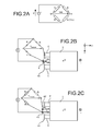
- the measurement of the force imposed by the movement of the moving mass 3 on the strain gauge or 4 or 6 can be achieved by means of a Wheatstone bridge (whose principle is schematized in the Figure 2A ) positioned to evaluate a variation of the resistance formed by the gauge.
- Rx is the resistance of the gauge at rest (the moving mass is not moving)
- a rotation of the mass 3 around the axis H will result in a variation of this resistance, which becomes Rx (1 + ⁇ ).
- the bridge measures the value of ⁇ .
- This Wheatstone bridge can be applied in two variants to the device according to the invention described in the first embodiment, variants that depend on the structure of the strain gauge.
- the piezoresistive strain gauge is composed of a single branch 4, the current supply is therefore by the pivot zone (for example by the pivot 5) and the current output by the branch 4 (or vice versa).
- the Wheatstone bridge measures the variation of the resistance Rx 'of the single branch of the strain gauge 4 and the resistance formed by the supply of current passing through the pivot zone 5 and a part of the moving mass 3.
- the suspended strain gauge 4 is formed of two arms 40 and 40 'parallel. It is located in the same plane parallel to that of the seismic mass.
- a layer electrically insulating is deposited between the gauge 4 and the mobile mass 3. The current is fed by an arm 40, and leaves by the second arm 40 '( Figure 2C ), Or vice versa.
- a second embodiment of the invention illustrated in Figures 3A and 3B , also applicable to the embodiments of Figures 9A-9D (Except for directly the position of the second zone, or pivot zone), the general principle of the accelerometer type device of the first embodiment, but has other variants.
- it comprises a mobile mass 3 associated with a substrate having an upper face 21 and a lower face 22, the mobile mass having an upper face 11, in the same plane N1 as the upper face of the substrate 21 and a lower face 12.
- the means for the mobile mass 3 can not move in the plane of the sensor (xOy plane of the figure 3A ) is produced by a large width L of the pivot zone 5 "in the direction of the axis of rotation H ( figure 3B ).
- This width may be close to the width of the mass 3 itself, measured parallel to the axis H while advantageously being smaller than the width of the moving mass 3.
- the height h of the pivot zone 5 " is represented here smaller than that of the moving mass T and greater than the thickness e of the strain gauges, as in FIG. Figure 1E or 1F , with the same result, already explained above.
- the pivot zone can also be of the same thickness as the moving mass, as in the case illustrated in FIG. Figure 1A .
- the pivot zone could be disposed at the top of the device, so that it has as a common plane, with the mass 3, the plane N1, the upper plane thereof.
- a differential arrangement allows a movement of the moving mass along the sensitive detection axis, a movement along the axis Z in the case of the invention, imposes on each of the two gauges a constraint in the opposite direction.
- at least one of the gauges will be in tension and at least one other will be in compression.
- gauges 6 and 6 are located above the upper plane N1 of the mobile mass 3, or close to this plane, plane located on the side of the front face of the substrate 2.
- the lower part of these gauges is therefore located in the upper plane N1 of the mobile mass 3. They are advantageously formed by deposition.
- they could be formed by etching and located at the lower plane N2 of the lower face 12 of the moving mass 3 (in which case the lower part of the gauges would be in this plane N2). They are parallel to each other and are both oriented perpendicular to the H axis (see figure 3A ). They are also connected to a fixed part 50 of the device.
- a displacement of the mobile mass 3 along J creates a pulling force F on one of the two gauges 6, 6 'and compression on the other gauge 6', 6.
- the force can therefore be measured differentially.
- the interest of this assembly is that the measurement of the stress can be done by difference between the values of the constraints measured on the gauges. Thus one can get rid of parasitic stresses (for example due to temperature), which, identical for the two gauges 6 and 6 ', are canceled during the differential measurement. This provides better measurement accuracy.
- the two gauges are mounted in differential.
- this embodiment of the invention may comprise extensions 32 and 33 of the mobile mass 3, in the plane of this movement. ci and substantially parallel to the axis H, which do not interfere with the movement of the mass 3 and which allow the points of application of the force on the gauges to be in line with the pivot axis H. These points application are then in a plane containing the axis H and perpendicular to the planes of the sensor and the substrate. This increases the lever arm and therefore improves the sensitivity of the sensor.
- the different zones are advantageously such that it is easily possible to position the point of application of the stresses, originating from a movement of the moving mass 3, on the gauges at This position is advantageously formed by forming extensions (31, 32, 33) in the region of first thickness forming a mobile mass. These extensions, so as not to modify the positioning of the pivot axis H, are not in contact with the pivot zone 5.
- the gauges, in contact with these extensions are preferably not located above the pivot zone 5 that is, there is no plane perpendicular to the torsion axis H which passes through both a gauge and a part of the pivot zone.
- the strain gauge (s) can also be a detection resonator.
- the differential measurement of the stresses is done by means of an electronic device able to calculate the stresses applied to each of the strain gauges from the variations of vibration frequency when a stress is applied.
- This electronic device is also able to calculate a subtraction of one of the stresses, measured on a first gauge relative to another constraint, measured on a second gauge.
- the differential mode measurement of the resistance variations imposed by a movement of the mobile mass 3 is advantageously carried out by means of a Wheatstone bridge, presented in Figure 3C and 3D .
- the 4 branches each have a resistance of value R.
- a measurement of voltage V AB between two points A and B opposite of the bridge makes it possible to measure the difference 2 ⁇ R between the resistances arranged on either side of the bridge.
- one of these two points of values R (1 + ⁇ ) and R (1- ⁇ ) and which vary in opposite directions from each other ( figure 3C ).
- the two gauges 6, 6 'of the 3D figure can each form an arm of a differential Wheatstone bridge. At each of these two gauges is associated, at rest, a resistance R of known value.
- a point B of measurement of the voltage is chosen between the two gauges 6 and 6 ', here on the pivot zone 5 ".
- a rotation of the moving mass 3 induces the application of opposite stresses on the two gauges and therefore a stress variation ⁇ R on one of the gauges and - ⁇ R on the other of the two gauges.
- the Wheatstone bridge is formed with two other resistors 140, 140 ', as illustrated in FIG. 3D figure . Another measurement point A is positioned between these two resistors.
- the differential Wheatstone bridge makes it possible to calculate the variation of resistance 2 ⁇ R between the resistances of the gauges, variation of resistance which is imposed on the strain gauges 6, 6 'by the rotation of the moving mass 3.
- This method makes it possible to to overcome the noise due to parasitic resistance variations of the strain gauges, for example due to thermal expansion.
- the current supply is made for example by one of the gauges 6, and the output of the current by the second strain gauge 6 '.
- a third embodiment of the invention, of the mass sensor type, is presented in the Figures 4A to 4D .
- This sensor can be applied to the realization of a chemical sensor.
- This device can be based on the basic structure of one or other of the first embodiments of the invention.
- such a device comprises a first zone, comparable to a mobile mass 3, connected to the substrate 2 constituting the sensor by a pivot zone which may have a thickness less than or equal to the first zone.
- This pivot zone may have a common plane with the mobile mass 3, at least along the lower face 12 of the mobile mass 3.
- the second zone (pivot zone) is such that the movements of the mobile mass 3 are limited to a rotation around it an axis H, included in the plane of the substrate, passing through the second zone. The movement is therefore again of the "out of plane" type of the substrate.
- a third zone comprising at least one strain gage.
- the strain gauge 4 may be of the detection resonator type or it may advantageously be of the suspended resistance variable gauge type, preferably of the piezoresistive type, with a single or double gauge.
- strain gauges 4 and 4 ' there may be several strain gauges 4 and 4 ', preferably positioned in differential.
- the structure represented is of the type of Figures 1A and 1B but we can also take, for example, that of one of the Figures 9A - 9D .
- This vibrating means may be in the form of an electrode 7 positioned under all or part of the moving mass; the periodically variable powering of the electrode 7 leads to a setting in motion of the mobile mass 3 according to a vibration of the same period as the excitation ( Figures 4A and 4B ).
- the mass 3 is then made of conductive or semiconductive material, for example metal or silicon doped at more than 10 15 at / cm 3 .
- the vibrating means may be formed by a bimetallic strip composed of a conductive layer 70, for example a metal layer, deposited at least partially above the pivot axis H and partially on the moving mass, electrically isolated from the mass mobile 3 by an insulating layer 71, this deposited layer having a coefficient of thermal expansion different from that of the material constituting the mobile mass ( figure 4C and 4D ).
- the movement of the moving mass is then effected by a difference in the expansions between the two materials during a local rise in temperature obtained for example by the passage of a current in the structure, resulting in a bimetallic effect at the of the hinge formed by the pivot zone 5.
- the means for vibrating the mobile mass may be composed of a layer of piezoelectric material 80 deposited over at least a portion of the mobile mass from which it is separated by a layer 71 of material insulation, connected at both ends to a periodically variable power-up system ( Figures 4E ). Setting under periodic tension of the piezoelectric layer induces a periodic deformation thereof and thus a vibration of the moving mass 3.
- the power is for example by the presence, firstly above the piezoelectric layer electrical 80 and secondly between the piezoelectric layer and the insulating layer 71 of electrodes 90, 90 ', connected to a voltage generator.
- the mobile mass 3 if the mobile mass 3 adsorbs or absorbs molecules on its surface or in its volume (for example after functionalization of this surface or this volume), the overall mass increases. This results in a variation of the vibration frequency.
- a coating allowing the selective adsorption of a molecule or a type of molecule.
- This coating may be, for example, a layer of specific material, for example a polymer-type functionalization layer. It is then possible to go back by calculation to the quantity of adsorbed molecules.
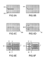
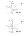
- a first method of producing a device according to the invention will be described in connection with the Figures 5A-5G and 6A-6F . It corresponds to the case of an engraved gauge (that of the Figure 1A ).
- the gauge is here of resonator type.
- This first method implements an epitaxy of a semiconductor material (in this case silicon, but this method can also be applied to the case of SiGe).
- a semiconductor material in this case silicon, but this method can also be applied to the case of SiGe.
- An SOI 200 substrate is first selected ( Figure 5A ). For example, it comprises a layer 220 of Si 0.5 ⁇ m thick for a layer 240 of SiO 2 oxide 1 ⁇ m thick.
- the etching is stopped on the layer 240 of SiO 2 .
- a layer (not shown) of SiO 2 for example of thickness 0.5 ⁇ m, is then deposited, followed by planarization with a stop on the layer 220 of Si, then with a deposit 320 of SiO 2 , for example about 0.4 ⁇ m thick ( Figure 5B ).
- An epitaxy 350 of silicon is then carried out ( Figures 5D and 6C ), on the initial surface layer 220 of semiconductor.
- the thickness of the epitaxial layer may be greater than the thickness of the layer 320, for example about 4 microns.
- the device is finally released by HF etching (wet or vapor) of the layer 240 ( figures 5G and 6F ), with stop at the time. On these figures 5G and 6F , we also see the gauge 4 clearly.
- This method can be adapted to the case of a piezoresistive gauge by eliminating the steps of formation of excitation electrodes and detection.
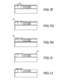
- a second method will be described in connection with the Figures 7A-7J and 8A-8H . It corresponds to the case of a deposited gauge (that of fig 1C).
- the gauge is of the polycrystalline silicon type here (it may alternatively be of monocrystalline silicon or SiGe mono- or polycrystalline type).
- An SOI 200 substrate is first selected ( Figure 7A ). For example, it has a layer 220 of Si of 4 .mu.m thick for a layer 240 of SiO 2 oxide of 1 .mu.m thick.
- a layer 260 of SiN is then deposited to electrically isolate the gauges from the substrate and serve as a barrier layer for planarization, of approximately 0.5 ⁇ m ( Figure 7B ).
- a deposit 280 ( figures 7E and 8C ) is made on the previously obtained structure, for the formation of the gauge.
- This is for example a deposit of WN (for example 20 nm thick) and Au (for example 100 nm thick).
- a piezoresistive type material such as polycrystalline silicon or polycrystalline SiGe. A lithography and etching operation then makes it possible to define the gauge.
- a lithography and etching operation then makes it possible to open contact zones 291 in this layer 290 ( figures 7G and 8E ).
- a deposit 292 ( figures 7H and 8F ) is performed in areas 291. This is for example a deposit of WN and Au. A lithography and etching operation then makes it possible to precisely define it.
- the device is finally released by HF etching (wet or vapor) of the SiO 2 deposit 270 ( figures 7I and 8G ), with stop at the time.
- the layer 260 of SiN is finally etched on the surface ( figures 7J and 8H ).
- This method can be adapted to the case of a resonator-type gauge by adding an excitation layer of piezoelectric or thermoelectric material above the metal or piezoresistive layer of the gauge 280, described in FIG. figures 7E and 8C .
- This deposit can be done before or after the definition of the shape of the gauge by lithography.
- the second case requires an additional lithography step to limit the deposition of the excitation layer on a portion of the gauge 280.
- the second zone, or pivot zone is substantially directed ( figures 3B, 3D ), or features ( Figures 1B , 1D , 1G , 2B, 2c ) portions disposed along an axis y (see in particular the diagram of Figures 1A and 1B ), which is substantially perpendicular to the axis H.
- pivot connection directed along the X axis, as illustrated on the Figures 9A - 9D , which are top views of a device according to the invention.
- the pivot connection is then biased according to a torsion mode, whereas, in the embodiments presented above, the pivot connection is biased in flexion.
- the strain gauge is connected to the ground in a plane parallel to the plane of the sensor but which does not contain the axis H.
- the reference numerals identical to those of the preceding figures designate identical or similar elements.
- the reference 50 designates a fixed zone of the device, to which are connected elements 55, 55 'constituting the second zone, and the third zone 4.
- the elements constituting the second zone are directed along the axis X, parallel to the axis H. These are two arms arranged on either side of the mass 3.
- connection of the third zone 4 with the mass 3 is carried out in a notch or a recessed zone 30 of this mass 3.
- the elements constituting the second zone are disposed inside the mass 3. It also comprises a recessed zone 30 ', inside which this time the elements 55, 55' constituting the second area that are arranged. This embodiment does not prevent the end of these elements 55,55 'are, again connected to a fixed part 50 of the device.
- the pivot connection can be made either outside the mass 3 or inside this mass (see in particular the embodiment of FIGS. Figures 9C and 9D ).
- Figures 9A - 9D are compatible with the realization of a mass sensor, as described above in connection with the Figures 4A - 4D .
Abstract
Description
L'invention concerne le domaine des micro-capteurs, notamment en silicium, par exemple les capteurs inertiels, notamment des accéléromètres.The invention relates to the field of micro-sensors, in particular silicon, for example inertial sensors, including accelerometers.
Elle trouve application dans des domaines variés, tels que l'automobile, la téléphonie mobile ou l'avionique.It finds application in various fields, such as automotive, mobile telephony or avionics.
De manière connue, les capteurs résonants peuvent être réalisés :
- Soit en technologie de volume, auquel cas l'élément sensible du capteur est réalisé sur toute l'épaisseur d'un substrat en silicium ou en quartz, en utilisant des gravures humides ; une telle technique est décrite dans le document
FR 2 763 694 - Soit en technologie de surface : cette technique est décrite dans le document
« Resonant accelerometer with self test », de M.Aikele et al., Sensors and Actuators, A92, 2001, p. 161-167
- Either in volume technology, in which case the sensing element of the sensor is made over the entire thickness of a silicon or quartz substrate, using wet etchings; such a technique is described in the document
FR 2 763 694 - Or in surface technology: this technique is described in the document
"Resonant accelerometer with self test", by M.Aikele et al., Sensors and Actuators, A92, 2001, p. 161-167
Les capteurs inertiels réalisés en technologie de volume sont basés sur une excitation électrostatique hors plan du résonateur. Ils sont d'encombrement important.Inertial sensors made in volume technology are based on off-plane electrostatic excitation of the resonator. They are of large size.
Ils nécessitent le report de 2 substrats, dont l'un sert à réaliser la (ou les) électrode(s) d'excitation/détection et le second sert à fermer la cavité sous vide. Il faut en outre contrôler le gap entre les substrats reportés. Les technologies mises en jeu sont donc lourdes.They require the transfer of 2 substrates, one of which is used to make the (or) electrode (s) excitation / detection and the second serves to close the cavity under vacuum. We must also control the gap between the substrates reported. The technologies involved are therefore heavy.
Dans ce type de technique, le résonateur de détection est aminci par rapport au substrat, et a donc une épaisseur différente de la masse mobile. Cet amincissement, qui est très mal contrôlé, est, entre autre, rendu nécessaire par le mode de vibration de la poutre qui se fait hors plan.In this type of technique, the detection resonator is thinned with respect to the substrate, and therefore has a thickness different from the moving mass. This thinning, which is very poorly controlled, is, among other things, made necessary by the vibration mode of the beam which is off plan.
Un autre problème de ce type de technique réside dans le positionnement du résonateur, qui ne peut pas être optimisé pour augmenter l'effet de bras de levier. En effet, afin de minimiser l'entrefer entre le résonateur et son électrode d'excitation, le résonateur est placé en surface du substrat. De manière optimum, le résonateur devrait se situer le plus près possible de la charnière (axe de rotation de la masse).Another problem with this type of technique is the positioning of the resonator, which can not be optimized to increase the leverage effect. Indeed, in order to minimize the gap between the resonator and its excitation electrode, the resonator is placed on the surface of the substrate. Optimally, the resonator should be as close as possible to the hinge (axis of rotation of the mass).
Il se pose donc le problème de trouver une nouvelle conception de composants, encore plus miniaturisés, permettant de surmonter les problèmes ci-dessus.There is therefore the problem of finding a new design of components, even more miniaturized, to overcome the above problems.
L'invention propose un nouveau type de capteur, réalisé en technologie planaire, permettant de détecter un effort hors plan appliqué à une masse mécanique libérée, et mettant en oeuvre une détection par une ou plusieurs jauges suspendues, par exemple de type piézorésistive ou résonateur (poutre ou diapason). Ce capteur selon l'invention permet de réaliser entre autres un accéléromètre ou un capteur de masse. Il permet en particulier une détection par jauge piézorésistive mais d'autres types de détection sont possibles.The invention proposes a new type of sensor, made in planar technology, for detecting an out-of-plane force applied to a released mechanical mass, and implementing detection by one or more suspended gauges, for example of the piezoresistive or resonator type ( beam or tuning fork). This sensor according to the invention makes it possible, inter alia, to carry out an accelerometer or a mass sensor. It allows in particular a detection by gauge piezoresistive but other types of detection are possible.
Ce capteur permet d'optimiser séparément les formes, matériaux et épaisseurs de la partie mobile (masse inertielle) et de la jauge utilisée pour la détection et la mesure de la contrainte.This sensor makes it possible to separately optimize the shapes, materials and thicknesses of the moving part (inertial mass) and of the gauge used for the detection and measurement of the stress.
Plus précisément, l'invention a pour objet un capteur MEMS de type de surface, réalisé dans un substrat, caractérisé en ce qu'il comporte :
- a) Une première zone, dite zone épaisse, présentant une première épaisseur, formant au moins une masse mobile, dont une première et une deuxième surfaces sont respectivement dans un premier plan et un deuxième plan, parallèles entre eux; cette masse est à mouvement hors de ces plans,
- b) une deuxième zone, formant au moins une liaison pivot pour la masse mobile, reliée à la masse mobile et au substrat, l'axe de la liaison pivot, ou axe de torsion, étant dans le plan du capteur ou du substrat,
- c) une troisième zone, dite zone mince, d'épaisseur inférieure ou égale à celle de la deuxième zone, formant au moins une jauge de contrainte de type suspendue pour la détection du mouvement de la masse mobile autour de l'axe de la liaison pivot, cette troisième zone :
- s'étendant parallèlement ou dans un plan parallèle au plan du capteur ou du substrat mais ne contenant pas l'axe de torsion du pivot,
- s'étendant de plus perpendiculairement ou dans un plan perpendiculaire à l'axe de torsion du pivot,
- étant reliée à la première zone d'un coté par au moins un point d'application de contraintes et au substrat de l'autre coté, par exemple par des liaisons de type encastrement.
- a) a first zone, called thick zone, having a first thickness, forming at least one mobile mass, of which a first and a second surface are respectively in a first plane and a second plane, parallel to each other; this mass is moving out of these planes,
- b) a second zone, forming at least one pivot connection for the moving mass, connected to the moving mass and to the substrate, the axis of the pivot connection, or torsion axis, being in the plane of the sensor or of the substrate,
- c) a third zone, called a thin zone, of thickness less than or equal to that of the second zone, forming at least one suspended type of strain gauge for the detection of the movement of the mobile mass around the axis of the connection pivot, this third zone:
- extending in parallel or in a plane parallel to the plane of the sensor or the substrate but not containing the torsion axis of the pivot,
- extending perpendicularly or in a plane perpendicular to the torsion axis of the pivot,
- being connected to the first zone on one side by at least one stress application point and the substrate on the other side, for example by embedding type connections.
Un tel positionnement de la troisième zone permet d'avoir une épaisseur de la zone pivot indépendante de l'épaisseur de la troisième zone et permet de plus d'obtenir préférentiellement que le ou les point(s) d'application de contraintes imposées par la première zone sur la troisième zone soit à l'aplomb de l'axe pivot H, c'est-à-dire dans un plan perpendiculaire à N1 et/ou N2 contenant l'axe pivot H. Cela permet d'augmenter le bras de levier de la masse sismique sur les jauges de contraintes.Such a positioning of the third zone makes it possible to have a thickness of the pivot zone that is independent of the thickness of the third zone and also makes it possible to preferentially obtain the point (s) of application of the stresses imposed by the first zone on the third zone is in line with the pivot axis H, that is to say in a plane perpendicular to N1 and / or N2 containing the pivot axis H. This allows to increase the arm of lever of the seismic mass on the strain gages.
La deuxième zone a, suivant une direction perpendiculaire au plan du substrat, une partie inférieure et une partie supérieure, l'une de ces deux parties étant dans le premier plan ou dans le deuxième plan de la première zone, qui est donc dit plan commun aux première et deuxième zones. Autrement dit, la partie supérieure de la deuxième zone est située dans le premier plan (ou plan supérieur) de la première zone et/ou la partie inférieure de la deuxième zone est située dans le deuxième plan (ou plan inférieur) de la première zone.The second zone has, in a direction perpendicular to the plane of the substrate, a lower part and an upper part, one of these two parts being in the first plane or in the second plane of the first zone, which is therefore called common plane in the first and second zones. In other words, the upper part of the second zone is located in the first plane (or upper plane) of the first zone and / or the lower zone of the second zone is located in the second plane (or lower plane) of the first zone. .
La troisième zone a, suivant une direction perpendiculaire au plan du substrat, une partie inférieure et une partie supérieure, l'une de ces deux parties pouvant être dans le plan commun aux première et deuxième zones.The third zone has, in a direction perpendicular to the plane of the substrate, a lower part and an upper part, one of these two parts that can be in the plane common to the first and second zones.
Dans un dispositif selon l'invention, l'épaisseur de la deuxième zone (formant pivot) est indépendante de l'épaisseur de la troisième zone.In a device according to the invention, the thickness of the second zone (pivoting) is independent of the thickness of the third zone.
La différence d'épaisseur entre la troisième zone et la deuxième zone permet d'avoir une contrainte en tension ou en compression : si ces deux zones étaient d'une même épaisseur, on ne pourrait pas avoir accès indépendamment à ces contraintes. Dans le cas d'une détection par effet piezoélectrique, celui-ci serait alors annulé.The difference in thickness between the third zone and the second zone makes it possible to have a stress in tension or in compression: if these two zones were of the same thickness, one could not have access independently to these constraints. In the case of detection by piezoelectric effect, it would then be canceled.
De préférence, le ou les point(s) d'application de contraintes imposées par la première zone sur la troisième zone est à l'aplomb de l'axe pivot H, c'est-à-dire dans un plan perpendiculaire au premier plan et/ou au deuxième plan de la première zone et contenant l'axe pivot H. Cela permet d'augmenter le bras de levier de la masse sismique sur les jauges de contraintes.Preferably, the point (s) of application of stresses imposed by the first zone on the third zone is in line with the pivot axis H, that is to say in a plane perpendicular to the foreground and / or in the second plane of the first zone and containing the pivot axis H. This makes it possible to increase the lever arm of the seismic mass on the strain gages.
La première et la seconde zone peuvent être formées dans un ou des matériaux semi-conducteurs et/ou isolants. La première et la seconde zone peuvent être dans des matériaux identiques ou différents.The first and second zones may be formed in one or more semiconductor and / or insulating materials. The first and the second zone may be in identical or different materials.
On entend par capteur MEMS des capteurs comprenant des éléments microniques et/ou sub-microniques.By MEMS sensor is meant sensors comprising micronic and / or sub-micronic elements.
De préférence :
- la deuxième zone a une épaisseur inférieure à celle de la masse mobile,
- et/ou a une largeur, suivant la direction de l'axe pivot, inférieure à la largeur de la masse mobile suivant cette même direction,
- et/ou a une extension suivant une direction parallèle à l'axe pivot; la deuxième zone comporte par exemple deux portions allongées, chacune disposée d'un côté de la masse mobile, ou disposée dans une ouverture réalisée dans la masse mobile.
- the second zone has a thickness less than that of the moving mass,
- and / or has a width, in the direction of the pivot axis, smaller than the width of the moving mass along the same direction,
- and / or has an extension in a direction parallel to the pivot axis; the second zone comprises for example two elongate portions, each disposed on one side of the moving mass, or disposed in an opening made in the moving mass.
Dans un capteur selon l'invention la deuxième zone, formant une liaison pivot pour la masse mobile, ne permet qu'un mouvement de rotation de cette dernière autour de l'axe pivot, empêchant tout autre mouvement de la masse mobile. En particulier, la deuxième zone peut comporter plusieurs tronçons alignés le long de l'axe pivot.In a sensor according to the invention the second zone, forming a pivot connection for the moving mass, allows only a rotational movement of the latter around the pivot axis, preventing any further movement of the moving mass. In particular, the second zone may comprise several segments aligned along the pivot axis.
La masse mobile peut avoir une épaisseur strictement supérieure à celle de la deuxième zone (formant pivot). Cette dernière a elle même une épaisseur strictement supérieure à celle de la troisième zone, comportant la ou les jauges de contraintes, avantageusement supérieure à deux fois l'épaisseur de la troisième zone.The moving mass may have a thickness strictly greater than that of the second zone (forming a pivot). The latter itself has a thickness strictly greater than that of the third zone, comprising the strain gauge or gauges, advantageously greater than twice the thickness of the third zone.
La ou les jauges de contrainte et la masse mobile peuvent avoir un plan commun, qui peut être le plan inférieur de la masse. Les jauges et la masse mobile sont alors situées d'un même côté par rapport à ce plan. En variante elles peuvent avoir comme plan commun le plan supérieur de la masse. Les jauges sont alors situées d'un coté de ce plan et la masse mobile de l'autre coté.The strain gauge (s) and the moving mass may have a common plane, which may be the lower plane of the mass. The gauges and the moving mass are then located on the same side with respect to this plane. Alternatively they may have as a common plane the upper plane of the mass. The gauges are then located on one side of this plane and the moving mass on the other side.
De préférence, l'axe de la liaison pivot est dans un plan passant par le centre de gravité G de la masse mobile. Ce plan est parallèle au premier plan et au deuxième plan.Preferably, the axis of the pivot connection is in a plane passing through the center of gravity G of the moving mass. This plan is parallel to the foreground and the background.
La troisième zone peut comporter au moins deux jauges de contraintes, situées de manière anti-symétrique l'une par rapport à l'autre et par rapport :
- à un plan perpendiculaire au premier et deuxième plans de la masse mobile et contenant l'axe de torsion,
- et à un plan perpendiculaire à l'axe de torsion.
- at a plane perpendicular to the first and second planes of the moving mass and containing the torsion axis,
- and at a plane perpendicular to the torsion axis.
La ou les jauge(s) de contrainte peut être en matériau piézorésistif tel que du silicium mono cristallin ou poly-cristallin ou du SiGe, ou des nanofils, par exemple en silicium, ou des nanotubes, par exemple en carbone. Elle peut alors être utilisée comme jauge suspendue, dont on mesure alors la variation de résistance électrique en fonction de la contrainte qui y est exercée.The strain gauge (s) may be of piezoresistive material such as monocrystalline or polycrystalline silicon or SiGe, or nanowires, for example silicon, or nanotubes, for example carbon. It can then be used as a suspended gauge, whose electrical resistance variation is then measured as a function of the stress exerted on it.
Elle peut être réalisée par gravure dans un substrat semi-conducteur. En variante, elle peut être réalisée par dépôt d'un matériau piézorésistif tel que du silicium poly-cristallin, des nano-fils de silicium, des nanotubes de carbones. Alternativement, la jauge peut être dans un matériau, tel qu'un métal, pour lequel la déformation modifie la résistance, par des effets géométriques.It can be performed by etching in a semiconductor substrate. As a variant, it can be produced by depositing a piezoresistive material such as polycrystalline silicon, silicon nano-wires or carbon nanotubes. Alternatively, the gauge may be in a material, such as a metal, for which the deformation modifies the resistance, by geometric effects.
Des nanofils, en particulier des nanofils en silicium, sont des structures de forme allongée suivant une direction, cette direction étant nommée longueur. Les dimensions transverses, dans une section perpendiculaire à cette direction sont très inférieures à cette longueur. Ces dimensions transverses sont typiquement inférieures à 100 nm, préférentiellement inférieures à 50 nm ou 40 nm et avantageusement inférieures à 20 nm. Des nanofils orientés suivant une direction X, contenue dans le plan d'un substrat, peuvent être obtenus en gravant une poutre de silicium suivant des directions transverses Y et Z, ou par croissance d'un nanofil, par exemple par dépôt SLV catalysé.Nanowires, in particular silicon nanowires, are elongated structures in one direction, this direction being called length. The transverse dimensions in a section perpendicular to this direction are much smaller than this length. These transverse dimensions are typically less than 100 nm, preferably less than 50 nm or 40 nm and advantageously less than 20 nm. Nanowires oriented in a direction X, contained in the plane of a substrate, can be obtained by etching a silicon beam in transverse Y and Z directions, or by growth of a nanowire, for example by catalyzed SLV deposition.
La ou les jauge(s) peuvent être du type simple branche ou du type double branche.The gauge (s) may be of the single branch type or the double branch type.
La jauge, par exemple à résistance variable, peut être du type simple branche, un courant pouvant par exemple rentrer par la jauge et sortir par une des zones de pivot ou inversement. En variante, la jauge peut être du type double branche, un courant pouvant entrer par une des branches et sortir par une autre. Les deux branches peuvent être parallèles entre elles, une isolation électrique étant préférentiellement prévue entre d'une part la jauge et d'autre part la première zone.The gauge, for example variable resistance, may be of the single branch type, a current may for example enter through the gauge and out through one of the pivot areas or vice versa. Alternatively, the gauge may be of the double branch type, a current can enter through one of the branches and out another. The two branches may be parallel to each other, an electrical insulation being preferably provided between the gauge and the first zone.
Alternativement, la ou les jauge(s) de contrainte peut comporter un résonateur de détection à vibration dans le plan du substrat, comportant au moins une lame vibrante, un moyen d'excitation et un moyen de détection de la vibration.Alternatively, the strain gauge (s) may comprise a vibration detection resonator in the plane of the substrate, comprising at least one vibrating plate, an excitation means and a means for detecting the vibration.
La jauge de contrainte peut donc être un résonateur de détection, par exemple de type poutre ou diapason, dont on mesure alors la variation de fréquence en fonction de la contrainte qui y est exercée.The strain gauge can therefore be a detection resonator, for example of the beam or tuning fork type, which is then measured for the variation of frequency according to the stress exerted on it.
La mise en vibration de la jauge dans le plan du substrat peut se faire par des moyens électrostatiques. Le résonateur de détection est excité à la résonance. La variation de fréquence de vibration du résonateur de détection est fonction de la contrainte exercée par la masse.The vibration of the gauge in the plane of the substrate can be done by electrostatic means. The detection resonator is excited at resonance. The variation of the vibration frequency of the detection resonator is a function of the stress exerted by the mass.
L'excitation de la lame vibrante et/ou la détection de la résonance peut alors se faire par des moyens électrostatiques par le biais d'au moins une électrode disposée, par rapport à la lame vibrante, dans la direction de vibration.The excitation of the vibrating blade and / or the detection of the resonance can then be done by electrostatic means by means of at least one electrode arranged, with respect to the vibrating blade, in the direction of vibration.
La détection de la résonance peut aussi se faire par le biais de moyens piézorésistifs disposés sur la lame vibrante.The detection of the resonance can also be done by means of piezoresistive means arranged on the vibrating blade.
Les vibrations peuvent donc être mesurées par des électrodes disposées dans le plan du capteur. Ou bien, la jauge est excitée par des moyens électrostatiques, et les contraintes mesurées, par des moyens piézoélectriques disposées sur le résonateur.The vibrations can therefore be measured by electrodes arranged in the plane of the sensor. Or, the gauge is excited by electrostatic means, and the measured stresses, by piezoelectric means disposed on the resonator.
Un capteur selon l'invention peut être un capteur de type accéléromètre, la contrainte appliquée par la masse étant due à l'inertie de la masse lors d'un déplacement de l'ensemble du capteur.A sensor according to the invention may be an accelerometer-type sensor, the stress applied by the mass being due to the inertia of the mass during a displacement of the entire sensor.
Dans ce cas, une accélération hors du plan du capteur va faire pivoter la première zone, qui forme masse mobile, d'un angle α autour de l'axe de la liaison pivot de la deuxième zone. Cette rotation de la masse mobile va exercer une contrainte sur la jauge de contraintes. Dans le cas où la jauge est un résonateur, cette contrainte induit une variation de sa fréquence et/ou de l'amplitude de vibration. Dans le cas où la jauge est de type piezorésistive ou du type jauge métallique suspendue, cette contrainte induit une variation de sa résistance électrique, proportionnelle à la contrainte exercée. Il est alors possible de calculer l'accélération.In this case, an acceleration outside the plane of the sensor will rotate the first zone, which forms mobile mass, by an angle α around the axis of the pivot connection of the second zone. This rotation of the moving mass will exert a constraint on the strain gauge. In the case where the gauge is a resonator, this constraint induces a variation of its frequency and / or the amplitude of vibration. In the case where the gauge is of the piezoresistive type or of the suspended metal gauge type, this constraint induces a variation of its electrical resistance, proportional to the stress exerted. It is then possible to calculate the acceleration.
Dans un capteur selon l'invention, l'axe pivot et l'axe central de la jauge sont dans deux plans différents, parallèles au plan du capteur ou du substrat dans lequel celui-ci est réalisé. La contrainte sur la jauge est amplifiée par le bras de levier formé entre le centre de gravité G de la masse mobile, où s'applique la force due à l'accélération, l'axe pivot et le point d'application de la contrainte sur la jauge. Plus ce point d'application est proche de l'axe pivot H, sans toutefois être sur cet axe, plus la contrainte mesurée est importante.In a sensor according to the invention, the pivot axis and the central axis of the gauge are in two different planes, parallel to the plane of the sensor or the substrate in which it is made. The stress on the gauge is amplified by the lever arm formed between the center of gravity G of the moving mass, where the force due to the acceleration, the pivot axis and the point of application of the stress apply. the gauge. The more this point of application is close to the pivot axis H, but not on this axis, the greater the measured stress is important.
Le point d'application de la contrainte sur la jauge est préférentiellement situé à l'aplomb de l'axe pivot. De préférence encore, l'axe pivot est situé dans un même plan, parallèle à celui du capteur, que le centre de gravité de la masse mobile.The point of application of the stress on the gauge is preferably located vertically above the pivot axis. More preferably, the pivot axis is located in the same plane, parallel to that of the sensor, the center of gravity of the mobile mass.
Un dispositif selon l'invention peut en outre comporter des moyens de mise en vibration ou en mouvement de la masse mobile, notamment pour la réalisation de capteurs chimiques ou capteurs de masse. Ces moyens de mise en vibration ou en mouvement de la masse mobile peuvent comporter:
- une électrode présente sur le substrat en regard de l'une des faces principales de la masse mobile ; cette électrode peut être reliée à un générateur de tension apte à produire une tension périodiquement variable, la masse mobile étant alors reliée au même générateur de tension,
- ou une couche de matériau conducteur déposée sur la masse mobile et reliée au substrat, isolée électriquement de la masse mobile, par exemple par une couche isolante, formant un bilame avec la masse mobile ; cette couche peut être reliée à un générateur de tension apte à produire une tension périodiquement variable,
- ou une couche de matériau piézoélectrique, déposée sur la masse mobile et reliée au substrat ; cette couche peut être reliée électriquement à des moyens de production d'une tension périodiquement variable au sein du matériau piézoélectrique, par exemple des électrodes présentes sur et sous la couche piézoélectrique.
- an electrode present on the substrate facing one of the main faces of the mass mobile; this electrode can be connected to a voltage generator capable of producing a periodically variable voltage, the mobile mass then being connected to the same voltage generator,
- or a layer of conductive material deposited on the mobile mass and connected to the substrate, electrically isolated from the mobile mass, for example by an insulating layer, forming a bimetallic strip with the mobile mass; this layer can be connected to a voltage generator capable of producing a periodically variable voltage,
- or a layer of piezoelectric material deposited on the mobile mass and connected to the substrate; this layer may be electrically connected to means for producing a periodically variable voltage within the piezoelectric material, for example electrodes present on and under the piezoelectric layer.
Des moyens de production d'une tension périodiquement variable peuvent comporter :
- des électrodes entre lesquelles est déposée le matériau piézoélectrique,
- un générateur de tension relié aux dites électrodes.
- electrodes between which the piezoelectric material is deposited,
- a voltage generator connected to said electrodes.
Une variation de tension ou de courant imposée au moyen de mise en vibration conduit à une déformation locale de la masse et donc à une mise en mouvement. Ce mouvement devient une vibration si l'impulsion donnée par la zone de mise en vibration est due à, par exemple, l'impulsion d'un courant alternatif.A variation in voltage or current imposed on the vibrating means leads to a local deformation of the mass and therefore to a setting in motion. This movement becomes a vibration if the pulse given by the vibrating zone is due to, for example, the pulse of an alternating current.
L'invention concerne donc également un capteur de masse chimique de type résonateur, comportant un dispositif selon l'invention muni de moyens de mise en vibration de la masse mobile. La masse mobile mise en vibration peut alors être désigné sous l'appellation « poutre vibrante ».The invention therefore also relates to a resonator-type chemical mass sensor comprising a device according to the invention provided with means for vibrating the mobile mass. The vibrating moving mass can then be referred to as the "vibrating beam".
Avantageusement, la poutre vibrante peut comporter en outre à sa surface des moyens pour sélectionner des molécules ou un type ou plusieurs types de molécules ou des familles de molécules pouvant être adsorbé ou absorbé à la surface, par exemple au moyen de radicaux de molécules donnés ou d'une couche de matériau sensible à un seul type de molécule.Advantageously, the vibrating beam may further comprise at its surface means for selecting molecules or a type or several types of molecules or families of molecules that can be adsorbed or absorbed on the surface, for example by means of radicals of given molecules or a layer of material sensitive to a single type of molecule.
Par exemple, la surface de la poutre vibrante peut être recouverte par un matériau réagissant de façon particulière à un élément chimique et/ou biochimique et/ou comporte des molécules d'accroche spécifiques à une molécule ou une famille de molécules.For example, the surface of the vibrating beam may be covered by a material that reacts in a particular way to a chemical and / or biochemical element and / or has attachment molecules that are specific to a molecule or a family of molecules.
Ainsi, vibrant dans un milieu contenant la ou les molécules ciblées, la poutre vibrante voit sa masse augmenter au fur et à mesure que des molécules sont adsorbées. La fréquence de vibration de la poutre vibrante varie alors et les contraintes appliquées sur les jauges de contraintes sont modifiées.Thus, vibrating in a medium containing the target molecule or molecules, the vibrating beam sees its mass increase as and when molecules are adsorbed. The vibration frequency of the vibrating beam then varies and the stresses applied to the strain gauges are modified.
Un tel dispositif peut être utilisé pour détecter la présence et/ou la concentration d'une ou plusieurs molécules dans un milieu.Such a device can be used to detect the presence and / or concentration of one or more molecules in a medium.
Un avantage de ce dispositif, par rapport à un capteur chimique de masse dont l'axe de déplacement de la poutre vibrante est dans le plan, est le suivant. La mise en vibration, selon un axe perpendiculaire au plan du substrat, pour une poutre vibrante, en particulier une poutre de largeur importante, offrant une surface de capture de molécules importante, est plus facile à réaliser en technologie de couches minces qu'une mise en vibration dans le plan.An advantage of this device, compared to a chemical mass sensor whose axis of displacement of the vibrating beam is in the plane, is as follows. The vibration, along an axis perpendicular to the plane of the substrate, for a vibrating beam, in particular a beam of large width, offering a large molecule capture surface, is easier to achieve in thin film technology than a setting. in vibration in the plane.
Lors de la mise en oeuvre d'un dispositif selon l'invention, la masse mobile est avantageusement dans un environnement gazeux ou dans le vide. Dans le cas d'un capteur de masse, ou capteur chimique, la masse mobile, ou poutre vibrante, est amenée en contact avec le fluide porteur.When implementing a device according to the invention, the mobile mass is advantageously in a gaseous environment or in a vacuum. In the case of a mass sensor, or chemical sensor, the moving mass, or vibrating beam, is brought into contact with the carrier fluid.
Une jauge de contrainte de type résonateur de détection, quand à elle, est avantageusement dans un milieu proche du vide. En effet, une atténuation due à un milieu gazeux aurait pour effet de dégrader le facteur de qualité du résonateur et donc de diminuer la résolution du capteur.A strain gauge of the detection resonator type, when it is, is advantageously in a medium close to vacuum. In fact, an attenuation due to a gaseous medium would have the effect of degrading the quality factor of the resonator and thus of decreasing the resolution of the sensor.
Ainsi, pour ces raisons, un dispositif selon l'invention, aura préférentiellement une jauge de contrainte à résistance variable, par exemple du type piézo-résisitif.Thus, for these reasons, a device according to the invention will preferably have a variable resistance strain gauge, for example of the piezoresistive type.
Dans un dispositif selon l'invention, toute les connections électriques peuvent se faire par intégration sur la face avant du substrat, avant et/ou après formation du dispositif suivant l'invention.In a device according to the invention, all the electrical connections can be done by integration on the front face of the substrate, before and / or after forming the device according to the invention.
L'invention a également pour objet un procédé de fabrication d'un capteur MEMS de type de surface, caractérisé :
- en ce que le capteur est fabriqué dans une couche de matériau semi-conducteur, par exemple du silicium monocristallin ou polycristallin ou dans une couche de SiGe, présente au dessus d'une couche sacrificielle, elle-même par exemple déposée sur un substrat semi-conducteur ou isolant de type verre,
- et en ce que le procédé consiste en la réalisation de :
- a) une première zone, présentant une première épaisseur, formant au moins une masse mobile,
- b) une deuxième zone, reliée à la masse mobile de façon à ce que le seul axe de mouvement permis à la masse mobile soit une rotation suivant un axe compris dans le plan du capteur, dit axe de torsion du pivot, la deuxième zone formant ainsi une liaison pivot dans le plan du capteur,
- c) une troisième zone, dite zone mince, d'épaisseur plus faible que celle de la zone épaisse, formant au moins une jauge de contrainte de type suspendue pour la détection du mouvement de la masse mobile autour de l'axe de la liaison pivot, cette troisième zone :
- s'étendant dans un plan parallèle au plan du capteur mais ne contenant pas l'axe de torsion du pivot,
- s'étendant dans un plan perpendiculaire à l'axe de torsion du pivot,
- étant reliée à la masse mobile.
- in that the sensor is manufactured in a layer of semiconductor material, for example monocrystalline or polycrystalline silicon or in a SiGe layer, present above a sacrificial layer, itself for example deposited on a semiconductor substrate or insulator glass type,
- and in that the method consists in producing:
- a) a first zone, having a first thickness, forming at least one mobile mass,
- b) a second zone, connected to the moving mass so that the only axis of movement allowed to the moving mass is a rotation along an axis included in the plane of the sensor, said torsion axis of the pivot, the second zone forming thus a pivot connection in the plane of the sensor,
- c) a third zone, referred to as a thin zone, of smaller thickness than that of the thick zone, forming at least one suspended type of strain gauge for the detection of the movement of the mobile mass around the axis of the pivot connection , this third zone:
- extending in a plane parallel to the plane of the sensor but not containing the torsion axis of the pivot,
- extending in a plane perpendicular to the torsion axis of the pivot,
- being connected to the moving mass.
Les trois zones peuvent être formées par gravure d'une couche de matériau semi-conducteur, la gravure de la couche sacrificielle permettant de libérer l'élément mobile du capteur.The three zones may be formed by etching a layer of semiconductor material, etching the sacrificial layer to release the mobile element of the sensor.
Elles peuvent notamment être formées par gravure d'une couche superficielle de matériau semi-conducteur d'un substrat SOI, la couche d'oxyde du SOI servant de couche sacrificielle et d'isolant électrique pour les parties fixes.They can in particular be formed by etching a surface layer of semiconductor material of an SOI substrate, the SOI oxide layer serving as a sacrificial layer and electrical insulator for the fixed parts.
La zone mince peut être réalisée dans une couche superficielle déposée sur le substrat semi-conducteur, les deux premières zones formées par gravure d'une couche de matériau semi-conducteur, la gravure de la couche sacrificielle permettant de libérer l'élément mobile du capteur.The thin zone may be formed in a surface layer deposited on the semiconductor substrate, the first two zones formed by etching a layer of semiconductor material, etching the sacrificial layer to release the mobile element of the sensor. .
La deuxième zone peut être d'épaisseur comprise entre celle de la première zone et celle de la troisième zone. La deuxième zone peut être d'épaisseur égale à celle de la première zone.The second zone may be of thickness between that of the first zone and that of the third zone. The second zone may be of thickness equal to that of the first zone.
Ce procédé permet de réaliser un dispositif selon l'invention, tel que décrit ci-dessus. Les autres caractéristiques d'un dispositif selon l'invention s'appliquent donc à un procédé selon l'invention.This method makes it possible to produce a device according to the invention, as described above. The other characteristics of a device according to the invention therefore apply to a method according to the invention.
-
Les
figures 1A et 1B représentent, respectivement en vue de côté et de dessus, un capteur accélérométrique selon l'invention, de type planaire, avec axe sensible hors plan et jauge de contrainte gravée,TheFigures 1A and 1B represent, respectively in a side view and from above, an accelerometric sensor according to the invention, of planar type, with off-plane sensitive axis and etched strain gauge, -
les
figures 1C et1D représentent, respectivement en vue de côté et de dessus, un autre capteur accélérométrique selon l'invention, de type planaire, avec axe sensible hors plan et jauge de contrainte déposée,theFigures 1C and1D represent, respectively in a side view and from above, another accelerometer sensor according to the invention, of planar type, with off-plane sensitive axis and deposited strain gauge, -
les
figures 1E et 1F représentent, toutes deux en vue de côté, un autre capteur accélérométrique selon l'invention, de type planaire, avec axe sensible hors plan et jauge de contrainte, et zone de pivot d'épaisseur réduite,theFigures 1E and 1F represent, both in side view, another accelerometer sensor according to the invention, of planar type, with off-plane sensitive axis and strain gauge, and pivot zone of reduced thickness, -
la
figure 1G représente un capteur selon l'invention, dont la jauge de contrainte est du type résonateur de détection,thefigure 1G represents a sensor according to the invention, whose strain gauge is of the detection resonator type, -
les
figures 2A à 2C représentent des schémas d'un pont de Wheatstone (figure 2A ), appliqué à un dispositif selon l'invention, à jauge simple (figure 2B ) ou double (figure 2C ),theFIGS. 2A to 2C represent diagrams of a Wheatstone bridge (Figure 2A ), applied to a device according to the invention, with a simple gauge (Figure 2B ) or double (Figure 2C ) -
les
figures 3A et 3B représentent, respectivement en vue de côté et de dessus, un autre capteur accélérométrique selon l'invention, de type planaire, avec axe sensible hors plan et jauges de contraintes montées en différentiel ou en opposition,theFigures 3A and 3B represent, respectively in side view and from above, another accelerometer sensor according to the invention, of planar type, with off-plane sensitive axis and differential or opposing differential strain gauges, -
les
figures 3C et 3D représentent le schéma d'un pont de Wheatstone différentiel (figure 3C ) et son application à un dispositif selon l'invention, ayant deux jauges et ayant dans ce cas une zone pivot large (figure 3D ),theFigures 3C and 3D represent the schematic of a differential Wheatstone bridge (figure 3C ) and its application to a device according to the invention, having two gauges and having in this case a wide pivot zone (3D figure ) -
les
figures 4A à 4E représentent un schéma d'un dispositif selon l'invention du type capteur de masse vibrant, selon un premier (figures 4A et 4B ), un second (figures 4C et4D ), et un troisième (figure 4E ) mode de mise en vibration de la masse mobile,theFIGS. 4A to 4E represent a diagram of a device according to the invention of the vibrating mass sensor type, according to a first (Figures 4A and 4B ), a second (Figures 4C and4D ), and a third (figure 4E ) mode of vibration of the moving mass, -
les
figures 5A-5G et6A-6F , représentent un premier mode de réalisation d'un procédé selon l'invention,theFigures 5A-5G and6A-6F , represent a first embodiment of a method according to the invention, -
les
figures 7A-7J et8A-8H représentent un deuxième mode de réalisation d'un procédé selon l'invention.theFigures 7A-7J and8A-8H represent a second embodiment of a method according to the invention. -
les
figures 9A-9D représentent des variantes d'un dispositif selon l'invention.theFigures 9A-9D represent variants of a device according to the invention.
Différents modes de réalisation sont illustrés par les
Des propriétés communes aux divers modes de réalisation de l'invention vont d'abord être décrites. Les particularités de chacun des modes de réalisation seront ensuite présentées.Properties common to the various embodiments of the invention will first be described. The particularities of each of the embodiments will then be presented.
Un capteur selon l'invention est compris ou réalisé dans un substrat ou une plaquette 2, par exemple en matériau semi-conducteur, par exemple en silicium monocristallin ou polycristallin ou encore dans une couche de SiGe, déposée sur un substrat en silicium ou en un matériau de type verre. Cette plaquette a une face supérieure 21 (ou première face) et une face inférieure 22 (ou deuxième face). Ces références numériques sont représentées sur la
Les adjectifs « inférieur » et « supérieur » sont choisis à titre de commodité, mais n'expriment pas une position relative définitive de l'un des plans par rapport à l'autre. On peut aussi employer respectivement les expressions « première face » et « deuxième face ». La face dite inférieure de la masse 3 fait face, et est parallèle, à une face 22' du substrat mise à jour par gravure lors de la mise en oeuvre d'un procédé de réalisation du dispositif selon l'invention. Cette face 22' est par exemple comprise dans un plan N22' compris entre N2 et N22.The adjectives "inferior" and "superior" are chosen as a convenience, but do not express a definitive relative position of one plane relative to the other. The terms "first face" and "second face" can also be used respectively. The so-called lower face of the mass 3 faces, and is parallel to, a face 22 'of the substrate updated by etching during the implementation of a method for producing the device according to the invention. This face 22 'is for example included in a plane N22' between N2 and N22.
On définit un repère orthonormé, comportant deux axes perpendiculaires l'un par rapport à l'autre, X et Y, situés dans l'un des plans N définis ci-dessus, le troisième axe, Z, étant l'axe perpendiculaire aux plans N.An orthonormal coordinate system is defined, comprising two mutually perpendicular axes, X and Y, located in one of the N planes defined above, the third axis, Z, being the axis perpendicular to the planes NOT.
Un dispositif accélérométrique selon l'invention comporte une masse 3 d'une première épaisseur T, mesurée suivant la direction Z perpendiculaire aux faces ou au plan de la plaquette (de même que les épaisseurs mentionnées dans la suite de ce texte). Les plans de cette masse parallèles au plan N de la plaquette définissent les premier plan N1 et deuxième plan N2 du capteur. Cette masse 3 forme une masse mobile. Elle peut être en même matériau que le substrat 2. Elle est par exemple en silicium monocristallin ou polycristallin ou encore en SiGe, ou en un matériau de type verre. L'épaisseur T de la masse 3 est par exemple comprise entre quelques 500 nm et quelques 10 µm, par exemple 1 µm.An accelerometric device according to the invention comprises a mass 3 of a first thickness T, measured in the direction Z perpendicular to the faces or the plane of the wafer (as well as the thicknesses mentioned later in this text). The plans of this mass parallel to the plane N of the wafer define the first plane N1 and second plane N2 of the sensor. This mass 3 forms a mobile mass. It may be of the same material as the substrate 2. It is for example monocrystalline or polycrystalline silicon or SiGe, or a glass-type material. The thickness T of the mass 3 is for example between about 500 nm and some 10 microns, for example 1 micron.
En outre la masse 3 peut avoir une longueur L, mesurée selon l'axe Y du plan XY, comprise entre quelques micromètres et quelques centaines de µm, par exemple entre 10 µm ou 50 µm et 100 µm ou 200 µm ou 500 µm, et une largeur l, mesurée selon l'axe X du plan XY, qui peut être comprise entre quelques µm et quelques centaines de µm, par exemple entre 10 µm ou 50 µm et 100 µm ou 200 µm ou 500 µm.In addition, the mass 3 may have a length L, measured along the Y axis of the XY plane, of between a few micrometers and a few hundreds of μm, for example between 10 μm or 50 μm and 100 μm or 200 μm or 500 μm, and a width l, measured along the X axis of the XY plane, which may be between a few μm and a few hundreds of μm, for example between 10 μm or 50 μm and 100 μm or 200 μm or 500 μm.
Cette masse mobile est reliée à une deuxième zone 5, de deuxième épaisseur, qui forme ainsi une liaison pivot, aussi appelée charnière, d'axe H parallèle aux plans N définis ci-dessus (cet axe H est perpendiculaire au plan de la
La zone formant pivot comporte une partie supérieure et une partie inférieure disposées à des altitudes différentes selon l'axe Z. Elle est comprise entre les deux plans N1 et N2 qui englobent respectivement la face supérieure et la face inférieure de la masse 3. Si sa partie inférieure est dans le plan N2, le plan N2 est dit plan commun aux première et deuxième parties. En plus, ou en variante, la partie supérieure de la zone formant pivot peut être dans le plan N1, et le plan N1 est alors dit plan commun aux première et deuxième parties. Dans le mode de réalisation de la
Avantageusement, la géométrie et/ou les dimensions de la zone pivot sont telles que l'axe de rotation H est dans un plan parallèle aux plans N passant par le centre de gravité G de la masse mobile. Ceci permet de réduire la sensibilité aux accélérations transverses. On obtient cette position particulière de l'axe de rotation notamment quand les épaisseurs des première et deuxième zones sont égales suivant la direction Z.Advantageously, the geometry and / or the dimensions of the pivot zone are such that the axis of rotation H is in a plane parallel to the planes N passing through the center of gravity G of the mobile mass. This reduces the sensitivity to transverse accelerations. This particular position of the axis of rotation is obtained especially when the thicknesses of the first and second zones are equal in the Z direction.
La masse mobile 3 peut effectuer une rotation J autour de l'axe pivot et ne peut effectuer aucun autre mouvement dans le référentiel orthonormé XYZ lié au substrat, et notamment aucune rotation autour d'un autre axe. Dans les variantes du mode de réalisation des
De préférence :
- la deuxième zone a une épaisseur inférieure à celle de la masse 3 (y compris dans le cas des
figures 9A - 9D ), - et/ou a une largeur, suivant la direction de l'axe pivot H, inférieure à la largeur de la masse mobile 3 suivant cette même direction,
- et/ou comporte deux bras allongés, disposés de part et d'autre de la masse mobile 3 (
figures 9A - 9B ) ou dans une encoche 30' réalisée dans cette masse mobile (figures 9C et 9D ).
- the second zone has a thickness less than that of mass 3 (including in the case of
Figures 9A - 9D ) - and / or has a width, in the direction of the pivot axis H, smaller than the width of the moving mass 3 along this same direction,
- and / or comprises two elongated arms arranged on either side of the mobile mass 3 (
Figures 9A - 9B ) or in a notch 30 'made in this moving mass (Figures 9C and 9D ).
Ainsi, un mouvement de la masse mobile entraîne une déformation de la deuxième zone (zone pivot) et non pas une déformation de toute la masse mobile.Thus, a movement of the moving mass causes a deformation of the second zone (pivot zone) and not a deformation of the entire moving mass.
Enfin, une troisième zone 4 forme au moins une jauge de contrainte suspendue, d'épaisseur e plus faible que celle de la masse mobile T. Elle forme un moyen de détection du mouvement de la masse mobile 3. Préférentiellement, l'épaisseur e de la ou des jauge(s) est comprise entre, d'une part, 10 nm ou quelques dizaines de nm (par exemple 40 nm pour une jauge de contrainte du type nanofil ou 200 nm pour une jauge de contrainte suspendue en silicium polycristallin), et, d'autre part, quelques micromètres, par exemple 1 µm ou 5 µm ou 10 µm.Finally, a third zone 4 forms at least one suspended strain gauge with a thickness e which is smaller than that of the moving mass T. It forms a means of detecting the movement of the moving mass 3. Preferably, the thickness e of the gauge (s) is between, on the one hand, 10 nm or a few tens of nm (for example 40 nm for a strain gauge of the nanowire type or 200 nm for a suspended strain gage in polycrystalline silicon), and, on the other hand, a few micrometers, for example 1 micron or 5 microns or 10 microns.
Une jauge dite de type « suspendue » est maintenue entre deux parties dites parties d'extrémités. La partie de la jauge, dite partie centrale, disposée entre ces deux parties d'extrémités est de longueur non nulle et n'est en contact avec aucun autre matériau, et notamment aucun des matériaux parmi ceux composant le capteur.A so-called "suspended" type gauge is held between two so-called end portions. The portion of the gauge, said central portion, disposed between these two end portions is of non-zero length and is in contact with no other material, and in particular none of the materials of the sensor component.
En général une telle jauge est de forme allongée suivant une direction, et de longueur, dite longueur de la jauge, très grande dans cette direction devant chaque dimension mesurée dans une section perpendiculaire à ladite direction. Elle est maintenue en deux parties d'extrémités qui sont chacune de longueur faible ou très faible devant la longueur de la jauge ou de sa partie centrale.In general, such a gauge is of elongate shape in a direction, and of length, so-called length of the gauge, very large in this direction in front of each dimension measured in a section perpendicular to said direction. It is maintained in two end portions, each of which is of small or very small length in front of the length of the gauge or of its central portion.
Cette jauge de contrainte 4 s'étend dans un plan qui est parallèle au plan du capteur mais qui ne contient pas l'axe H de rotation de la liaison pivot, comme cela apparaît sur la
Comme on le comprend d'après les
Cette troisième zone est avantageusement en un matériau piézorésistif, par exemple en silicium monocristallin ou poly-cristallin, ou elle est composée de nanotubes de carbones, ou de nano-fils de silicium, ou en métal ... etc.This third zone is advantageously made of a piezoresistive material, for example made of monocrystalline or polycrystalline silicon, or it is composed of carbon nanotubes, or nano-wires of silicon, or of metal, etc.
Alternativement la jauge de contrainte, comme cela est présenté plus bas, peut être un résonateur de détection.Alternatively the strain gauge, as shown below, can be a detection resonator.
Une rotation J de la masse mobile autour de la liaison pivot Z se traduit par l'application d'une force F exercée sur la ou les jauge(s) de contrainte 4. Le point d'application P de la contrainte sur la jauge 4 est avantageusement dans un plan contenant l'axe H de la liaison pivot et perpendiculaire au plan du substrat ou à chacun des plans supérieur N2 et inférieur N1. Ce point d'application est alors dit « à l'aplomb» de l'axe H de rotation de la liaison pivot 5, ce qui permet de n'avoir, au premier ordre, qu'une contrainte axiale sur la jauge. Préférentiellement, la direction de la jauge de contrainte 4 est normale au plan contenant l'axe H qui est lui même perpendiculaire au plan du dispositif.A rotation J of the moving mass around the pivot connection Z is translated by the application of a F force exerted on the strain gauge (s) 4. The point of application P of the stress on the gauge 4 is advantageously in a plane containing the axis H of the pivot connection and perpendicular to the plane of the substrate or to each of the upper planes N2 and lower N1. This point of application is then said "in line" with the axis H of rotation of the pivot connection 5, which makes it possible to have, at first order, only an axial stress on the gauge. Preferably, the direction of the strain gauge 4 is normal to the plane containing the axis H which is itself perpendicular to the plane of the device.
Un premier mode de réalisation de l'invention concerne un dispositif de type accéléromètre (
Dans la variante des
En outre la jauge est disposée au-dessous de l'axe de torsion H. C'est-à-dire qu'il y a un plan commun entre la masse mobile, la deuxième zone (5, 5') et la jauge de contrainte 4, ce plan commun est le plan inférieur N2 de la masse mobile comportant la face inférieure 12 de la masse 3; on peut dire que la jauge est placée dans le plan inférieur de la masse mobile 3 dans la configuration représentée. Dans ce cas, la jauge est avantageusement formée par gravure. La jauge et la masse mobile sont situées d'un même coté du plan commun N2.In addition, the gauge is disposed below the torsion axis H. That is to say, there is a common plane between the moving mass, the second zone (5, 5 ') and the dipstick. constraint 4, this common plane is the lower plane N2 of the mobile mass comprising the lower face 12 of the mass 3; we can say that the gauge is placed in the lower plane of the moving mass 3 in the configuration shown. In this case, the gauge is advantageously formed by etching. The gauge and the moving mass are located on the same side of the common plane N2.
Une autre variante de ce mode de réalisation est représentée en
Dans les variantes des
Alternativement il est possible de réduire la hauteur de la zone pivot. C'est le cas des variantes des
La zone pivot 5 a alors sa partie inférieure dans le plan inférieur N2 du capteur, contenant la face arrière 12 de la masse 3 (leur plan commun est le plan N2, mais pas le plan N1). La zone pivot, d'épaisseur plus fine que la masse mobile, est donc positionnée proche de la partie inférieure de la masse mobile 3. L'axe H peut être alors lui aussi plus proche de cette partie inférieure de la masse 3. Cette situation modifie légèrement la force imposée à la jauge de contrainte 4, et donc la valeur et la précision des mesures.The pivot zone 5 then has its lower part in the lower plane N2 of the sensor, containing the rear face 12 of the mass 3 (their common plane is the plane N2, but not the plane N1). The pivot zone, whose thickness is thinner than the moving mass, is thus positioned close to the lower part of the moving mass 3. The axis H can then also be closer to this lower part of the mass 3. This situation slightly modifies the force imposed on the strain gauge 4, and thus the value and precision of the measurements.
En effet, dans ce cas là, la position basse de l'axe de rotation H, a pour effet d'augmenter la contrainte sur une jauge 4 située plus proche de l'axe pivot H, dans le plan inférieur N2 (cas de la
Inversement, dans ce cas d'une zone pivot localisée en partie basse de la masse 3, la contrainte appliquée sur une jauge de contrainte 6, située « en haut » de la masse mobile (cas de la
Le cas de la
Dans le cas de ces deux figures, la zone pivot 5 est d'épaisseur plus faible que la masse mobile 3.In the case of these two figures, the pivot zone 5 is of smaller thickness than the mobile mass 3.
Une autre variante d'une jauge de contrainte à résistance variable du type déposée, par exemple de type piézorésistive, peut comporter une jauge de contrainte composée de deux jauges parallèles. Ce mode alternatif sera présenté plus bas en liaison avec la
Quelle que soit la variante envisagée de ce mode de réalisation, alternativement, la jauge de contrainte peut être du type résonateur de détection à vibration dans le plan du substrat (
Ce résonateur comporte une lame vibrante 40, un moyen d'excitation 41 et un moyen de mesure 42.This resonator comprises a vibrating blade 40, an excitation means 41 and a measurement means 42.
Le moyen pour produire l'excitation de la lame vibrante peut être une électrode formant condensateur avec la lame vibrante 40 et reliée à un générateur de courant alternatif non schématisé (
Lors de l'application d'une contrainte suivant la longueur de la jauge de contrainte 4, perpendiculaire à la direction de vibration de la lame 40, la fréquence de vibration de la lame va varier. Cette variation est mesurée par le moyen de mesure 42.When applying a stress along the length of the strain gauge 4, perpendicular to the vibration direction of the blade 40, the vibration frequency of the blade will vary. This variation is measured by the measuring means 42.
Les moyens de mesure de la vibration de la lame vibrante 40 peuvent être de type piézorésistif, comme décrit dans
Dans la variante du premier mode de réalisation de l'invention décrite en
Dans les cas où la mesure de la contrainte est obtenue par des jauges à résistance variable (
Ce pont de Wheatstone peut s'appliquer selon deux variantes au dispositif selon l'invention décrit dans le premier mode de réalisation, variantes qui dépendent de la structure de la jauge de contrainte.This Wheatstone bridge can be applied in two variants to the device according to the invention described in the first embodiment, variants that depend on the structure of the strain gauge.
Dans une première variante, comme illustré en
Dans une deuxième variante (
Ce qui est expliqué ci-dessus, relativement aux jauges et à la troisième zone, est directement applicable aux modes de réalisation des
Un second mode de réalisation de l'invention, illustré en
Comme dans le premier mode de réalisation, il comporte une masse mobile 3 associée à un substrat comportant une face supérieure 21 et une face inférieure 22, la masse mobile comportant une face supérieure 11, dans le même plan N1 que la face supérieure du substrat 21 et une face inférieure 12.As in the first embodiment, it comprises a mobile mass 3 associated with a substrate having an upper face 21 and a lower face 22, the mobile mass having an upper face 11, in the same plane N1 as the upper face of the substrate 21 and a lower face 12.
Dans ce mode de réalisation, le moyen pour que la masse mobile 3 ne puisse se déplacer dans le plan du capteur (plan xOy de la
La hauteur h de la zone pivot 5" est représentée ici plus faible que celle de la masse mobile T et plus importante que l'épaisseur e des jauges de contraintes, comme en
Dans ce mode de réalisation de l'invention, deux jauges de contraintes 6 et 6' sont présentes. Elles sont positionnées de manière antisymétrique, comme le montre la
- par rapport à un plan perpendiculaire à l'axe H et passant par le centre de gravité G,
- et par rapport à un plan contenant l'axe H et perpendiculaire au plan du capteur.
- relative to a plane perpendicular to the axis H and passing through the center of gravity G,
- and with respect to a plane containing the axis H and perpendicular to the plane of the sensor.
On dira donc qu'elles sont montées en différentiel. Un montage différentiel permet qu'un mouvement de la masse mobile selon l'axe sensible de détection, un mouvement selon l'axe Z dans le cas de l'invention, impose sur chacune des deux jauges une contrainte de sens opposé. En particulier, pour tout mouvement selon l'axe Z, au moins une des jauges sera en tension et au moins une autre sera en compression.We will say that they are mounted in differential. A differential arrangement allows a movement of the moving mass along the sensitive detection axis, a movement along the axis Z in the case of the invention, imposes on each of the two gauges a constraint in the opposite direction. In particular, for any movement along the Z axis, at least one of the gauges will be in tension and at least one other will be in compression.
Ces deux jauges 6 et 6' sont situées au dessus du plan supérieur N1 de la masse mobile 3, ou voisines de ce plan, plan situé du coté de la face avant du substrat 2. La partie inférieure de ces jauges est donc située dans le plan supérieur N1 de la masse mobile 3. Elles sont avantageusement formées par dépôt.These two gauges 6 and 6 'are located above the upper plane N1 of the mobile mass 3, or close to this plane, plane located on the side of the front face of the substrate 2. The lower part of these gauges is therefore located in the upper plane N1 of the mobile mass 3. They are advantageously formed by deposition.
Alternativement, elles pourraient être formées par gravure et situées au niveau du plan inférieur N2 de la face inférieure 12 de la masse mobile 3 (auquel cas la partie inférieure des jauges serait dans ce plan N2). Elles sont parallèles entre elles et sont toutes deux orientées perpendiculairement à l'axe H (voir
Un déplacement de la masse mobile 3 selon J créé une force F de traction sur l'une des deux jauges 6, 6' et de compression sur l'autre jauge 6', 6. La force peut donc être mesurée de façon différentielle. L'intérêt de ce montage est que la mesure de la contrainte peut se faire par différence entre les valeurs des contraintes mesurées sur les jauges. Ainsi on peut s'affranchir des contraintes parasites (par exemple dues à la température), qui, identiques pour les deux jauges 6 et 6', s'annulent lors de la mesure différentielle. Cela permet d'obtenir une meilleure précision de mesure. On peut dire aussi que les deux jauges sont montées en différentiel.A displacement of the mobile mass 3 along J creates a pulling force F on one of the two gauges 6, 6 'and compression on the other gauge 6', 6. The force can therefore be measured differentially. The interest of this assembly is that the measurement of the stress can be done by difference between the values of the constraints measured on the gauges. Thus one can get rid of parasitic stresses (for example due to temperature), which, identical for the two gauges 6 and 6 ', are canceled during the differential measurement. This provides better measurement accuracy. We can also say that the two gauges are mounted in differential.
De façon à ce que les jauges mesurent bien les variations de forces imposées par le déplacement J de la masse mobile, ce mode de réalisation de l'invention peut comporter des extensions 32 et 33 de la masse mobile 3, dans le plan de celle-ci et sensiblement parallèlement à l'axe H, qui ne gênent pas le mouvement de cette masse 3 et qui permettent aux points d'application de la force sur les jauges d'être à l'aplomb de l'axe pivot H. Ces points d'application se trouvent alors dans un plan contenant l'axe H et perpendiculaire aux plans du capteur et du substrat. Cela permet d'augmenter le bras de levier et donc d'améliorer la sensibilité du capteur.In order for the gauges to measure well the variations of forces imposed by the displacement J of the moving mass, this embodiment of the invention may comprise extensions 32 and 33 of the mobile mass 3, in the plane of this movement. ci and substantially parallel to the axis H, which do not interfere with the movement of the mass 3 and which allow the points of application of the force on the gauges to be in line with the pivot axis H. These points application are then in a plane containing the axis H and perpendicular to the planes of the sensor and the substrate. This increases the lever arm and therefore improves the sensitivity of the sensor.
De même, dans les autres modes de réalisation de l'invention les différentes zones sont avantageusement telles qu'il soit aisément possible de positionner le point d'application des contraintes, provenant d'un mouvement de la masse mobile 3, sur les jauges à l'aplomb de l'axe de torsion H. Un tel positionnement se fait avantageusement en formant des extensions (31, 32, 33) dans la zone de première épaisseur formant masse mobile. Ces extensions, pour ne pas modifier le positionnement de l'axe pivot H, ne sont pas en contact avec la zone pivot 5. Ainsi, les jauges, en contact avec ces extensions, ne sont préférentiellement pas situées au dessus de la zone pivot 5, c'est-à-dire qu'il n'y a pas de plan perpendiculaire à l'axe de torsion H qui traverse à la fois une jauge et une partie de la zone pivot.Likewise, in the other embodiments of the invention the different zones are advantageously such that it is easily possible to position the point of application of the stresses, originating from a movement of the moving mass 3, on the gauges at This position is advantageously formed by forming extensions (31, 32, 33) in the region of first thickness forming a mobile mass. These extensions, so as not to modify the positioning of the pivot axis H, are not in contact with the pivot zone 5. Thus, the gauges, in contact with these extensions, are preferably not located above the pivot zone 5 that is, there is no plane perpendicular to the torsion axis H which passes through both a gauge and a part of the pivot zone.
Comme il a été présenté ci-dessus, la ou les jauge(s) de contraintes peut également être un résonateur de détection. Dans le cas de résonateurs de détection, la mesure différentielle des contraintes se fait au moyen d'un dispositif électronique apte à calculer les contraintes appliquées à chacune des jauges de contraintes à partir des variations de fréquence de vibration lorsqu'une contrainte est appliquée. Ce dispositif électronique est de plus apte à calculer une soustraction de l'une des contraintes, mesurée sur une première jauge par rapport à une autre contrainte, mesurée sur une deuxième jauge.As it was presented above, the strain gauge (s) can also be a detection resonator. In the case of detection resonators, the differential measurement of the stresses is done by means of an electronic device able to calculate the stresses applied to each of the strain gauges from the variations of vibration frequency when a stress is applied. This electronic device is also able to calculate a subtraction of one of the stresses, measured on a first gauge relative to another constraint, measured on a second gauge.
Dans le cas de jauges de contraintes du type à résistance variable, par exemple en matériau piézorésistif, la mesure en mode différentiel des variations de résistance imposées par un mouvement de la masse mobile 3 est avantageusement réalisée au moyen d'un pont de Wheatstone, présenté en
Dans un pont de Wheatstone différentiel les 4 branches ont chacune une résistance de valeur R. Une mesure de tension VAB entre deux points A et B opposés du pont permet de mesurer la différence 2αR entre les résistances disposées de part et d'autre de l'un de ces deux points, de valeurs R(1+α) et R(1-α) et qui varient en sens inverse l'une de l'autre (
Les deux jauges 6, 6' de la
Pour former un pont de Wheatstone différentiel, un point B de mesure de la tension est choisi entre les deux jauges 6 et 6', ici sur la zone pivot 5". De par la position des deux jauges (de part et d'autre du plan perpendiculaire au substrat passant par l'axe de rotation H) une rotation de la masse mobile 3 induit l'application de contraintes opposées sur les deux jauges et donc une variation de contrainte αR sur l'une des jauges et -αR sur l'autre des deux jauges.To form a differential Wheatstone bridge, a point B of measurement of the voltage is chosen between the two gauges 6 and 6 ', here on the pivot zone 5 ".From the position of the two gauges (from and else of the plane perpendicular to the substrate passing through the axis of rotation H) a rotation of the moving mass 3 induces the application of opposite stresses on the two gauges and therefore a stress variation αR on one of the gauges and -αR on the other of the two gauges.
Le pont de Wheatstone est formé avec deux autres résistances 140, 140', comme illustré sur la
Ainsi formé, le pont de Wheatstone différentiel permet de calculer la variation de résistance 2αR entre les résistances des jauges, variation de résistance qui est imposée aux jauges de contraintes 6, 6' par la rotation de la masse mobile 3. Cette méthode permet de s'affranchir du bruit dû à des variations de résistance parasites des jauges de contraintes, par exemple à cause de la dilatation thermique. L'amenée de courant se fait par exemple par une des jauges 6, et la sortie du courant par la deuxième jauge de contrainte 6'.Thus formed, the differential Wheatstone bridge makes it possible to calculate the variation of resistance 2αR between the resistances of the gauges, variation of resistance which is imposed on the strain gauges 6, 6 'by the rotation of the moving mass 3. This method makes it possible to to overcome the noise due to parasitic resistance variations of the strain gauges, for example due to thermal expansion. The current supply is made for example by one of the gauges 6, and the output of the current by the second strain gauge 6 '.
Le même type de mesure pourrait être obtenu avec deux jauges 4 et 4' situées au niveau du plan inférieur N2 de la masse mobile 3.The same type of measurement could be obtained with two gauges 4 and 4 'situated at the level of the lower plane N2 of the mobile mass 3.
Un troisième mode de réalisation de l'invention, de type capteur de masse, est présenté dans les
Ce dispositif peut être basé sur la structure de base de l'un ou l'autre des premiers modes de réalisation de l'invention.This device can be based on the basic structure of one or other of the first embodiments of the invention.
En effet, un tel dispositif comporte une première zone, assimilable à une masse mobile 3, reliée au substrat 2 composant le capteur par une zone pivot pouvant avoir une épaisseur inférieure ou égale à la première zone. Cette zone pivot peut avoir un plan commun avec la masse mobile 3, au moins selon la face inférieure 12 de la masse mobile 3. La seconde zone (zone pivot) est telle que les mouvements de la masse mobile 3 sont limités à une rotation autour d'un axe H, compris dans le plan du substrat, passant par la seconde zone. Le mouvement est donc là encore de type « hors plan » du substrat. A ces deux premières zones est ajoutée de plus une troisième zone, composant au moins une jauge de contrainte.Indeed, such a device comprises a first zone, comparable to a mobile mass 3, connected to the substrate 2 constituting the sensor by a pivot zone which may have a thickness less than or equal to the first zone. This pivot zone may have a common plane with the mobile mass 3, at least along the lower face 12 of the mobile mass 3. The second zone (pivot zone) is such that the movements of the mobile mass 3 are limited to a rotation around it an axis H, included in the plane of the substrate, passing through the second zone. The movement is therefore again of the "out of plane" type of the substrate. To these first two zones is added a third zone, comprising at least one strain gage.
Comme dans les modes de réalisations précédents, la jauge de contrainte 4 peut être de type résonateur de détection ou être avantageusement du type jauge suspendue à résistance variable, de préférence du type piézorésistif, avec une jauge simple ou double.As in the previous embodiments, the strain gauge 4 may be of the detection resonator type or it may advantageously be of the suspended resistance variable gauge type, preferably of the piezoresistive type, with a single or double gauge.
Comme pour les modes de réalisation précédents, il peut y avoir plusieurs jauges de contrainte 4 et 4', préférentiellement positionnées en différentiel.As for the previous embodiments, there may be several strain gauges 4 and 4 ', preferably positioned in differential.
Dans l'exemple illustrant ce mode de réalisation, la structure représentée est du type de celle des
La différence entre ce mode de réalisation de l'invention et les deux modes de réalisation précédents est la présence d'un moyen de mise en vibration de la masse mobile 3.The difference between this embodiment of the invention and the two previous embodiments is the presence of a means for vibrating the mobile mass 3.
Ce moyen de mise en vibration peut être sous la forme d'une électrode 7 positionnée sous tout ou partie de la masse mobile ; la mise sous tension variable périodiquement de l'électrode 7 conduit à une mise en mouvement de la masse mobile 3 selon une vibration de même période que l'excitation (
Alternativement, le moyen de mise en vibration peut être formé par un bilame composé d'une couche conductrice 70, par exemple métallique, déposée au moins partiellement au dessus de l'axe pivot H et partiellement sur la masse mobile, isolé électriquement de la masse mobile 3 par une couche isolante 71, cette couche déposée ayant un coefficient de dilatation thermique différent de celui du matériau composant la masse mobile (
Selon une autre alternative, le moyen de mise en vibration de la masse mobile peut être composé d'une couche de matériau piézoélectrique 80, déposée au dessus d'au moins une portion de la masse mobile dont elle est séparée par une couche 71 de matériau isolant, reliée à deux extrémités à un système de mise sous tension variable périodiquement (
Lors de la vibration de la masse mobile, une contrainte est appliquée sur les jauges de contraintes 4.During the vibration of the moving mass, a stress is applied on the strain gauges 4.
Dans le cas d'un capteur de masse chimique ou biochimique, si la masse mobile 3 adsorbe ou absorbe des molécules à sa surface ou dans son volume (par exemple après fonctionnalisation de cette surface ou de ce volume), la masse globale augmente. Il en résulte une variation de la fréquence de vibration.In the case of a chemical or biochemical mass sensor, if the mobile mass 3 adsorbs or absorbs molecules on its surface or in its volume (for example after functionalization of this surface or this volume), the overall mass increases. This results in a variation of the vibration frequency.
En mesurant la variation de la fréquence de résonance de la masse, il est possible de remonter par calcul à la masse adsorbée ou absorbée.By measuring the variation of the resonance frequency of the mass, it is possible to go back by calculation to the adsorbed or absorbed mass.
Dans un dispositif selon ce mode de réalisation, il est possible de fonctionnaliser la surface de la masse mobile par exemple en ajoutant sur la masse mobile un revêtement permettant l'adsorption sélective d'une molécule ou d'un type de molécule. Ce revêtement peut être par exemple une couche de matériau spécifique, par exemple une couche de fonctionnalisation de type polymère. Il est alors possible de remonter par calcul à la quantité de molécules adsorbées.In a device according to this embodiment, it is possible to functionalize the surface of the mobile mass, for example by adding to the mobile mass a coating allowing the selective adsorption of a molecule or a type of molecule. This coating may be, for example, a layer of specific material, for example a polymer-type functionalization layer. It is then possible to go back by calculation to the quantity of adsorbed molecules.
Un premier procédé de réalisation d'un dispositif selon l'invention va être décrit en liaison avec les
Ce premier procédé met en oeuvre une épitaxie d'un matériau semi-conducteur (ici du Silicium mais ce procédé peut aussi s'appliquer au cas du SiGe).This first method implements an epitaxy of a semiconductor material (in this case silicon, but this method can also be applied to the case of SiGe).
Un substrat SOI 200 est tout d'abord sélectionné (
Il est ensuite procédé à une lithographie puis une gravure de la couche 220 de Si pour définir une portion 300 de la jauge piézorésistive (
La gravure est arrêtée sur la couche 240 de SiO2. On procède ensuite au dépôt d'une couche (non représentée) de SiO2, par exemple d'épaisseur 0,5 µm, suivi d'une planarisation avec arrêt sur la couche 220 de Si, puis à un dépôt 320 de SiO2, par exemple d'environ 0.4 µm d'épaisseur (
On procède ensuite (
Une épitaxie 350 de Silicium est ensuite réalisée (
Un dépôt métallique Ti/Ni/Au, puis une lithographie par gravure, sont ensuite réalisés (
Il est ensuite procédé à une lithographie et à une gravure anisotrope (par exemple : DRIE) de la structure mécanique (
Le dispositif est enfin libéré par gravure HF (humide ou vapeur) de la couche 240 (
Ce procédé peut être adapté au cas d'une jauge piézorésistive en supprimant les étapes de formation d'électrodes d'excitation et de détection.This method can be adapted to the case of a piezoresistive gauge by eliminating the steps of formation of excitation electrodes and detection.
Un deuxième procédé va être décrit en liaison avec les
Un substrat SOI 200 est tout d'abord sélectionné (
Il est ensuite procédé à un dépôt d'une couche 260 de SiN, pour isoler électriquement les jauges du substrat et servir de couche d'arrêt à la planarisation, d'environ 0,5 µm (
Il est ensuite procédé à une lithographie, une gravure de la couche de SiN et à une gravure anisotrope (par exemple : DRIE) de la structure mécanique (
On procède ensuite (
Puis l'on procède à une étape de planarisation avec arrêt sur la couche SiN 260.Then we proceed to a planarization step with stop SiN layer 260.
Puis un dépôt 280 (
Un dépôt de SiO2 290, par exemple d'épaisseur 0,4 µm, est ensuite réalisé sur l'ensemble de la structure (
Une opération de lithographie et de gravure permet ensuite d'ouvrir des zones 291 de contact dans cette couche 290 (
Puis un dépôt 292 (
Le dispositif est enfin libéré par gravure HF (humide ou vapeur) du dépôt 270 de SiO2 (
La couche 260 de SiN est enfin gravée en surface (
Ce procédé peut être adapté au cas d'une jauge de type résonateur par l'ajout d'une couche d'excitation en matériau piézo-électrique ou thermoélectrique au dessus de la couche métallique ou piézorésistive de la jauge 280, décrite en
Dans les modes de réalisations qui ont été présentés ci-dessus, la deuxième zone, ou zone pivot, est sensiblement dirigée (
En variante, il est possible d'avoir une liaison pivot dirigée suivant l'axe X, comme illustrée sur les
De même que précédemment, la jauge de contrainte est reliée à la masse dans un plan parallèle au plan du capteur mais qui ne contient pas l'axe H.As before, the strain gauge is connected to the ground in a plane parallel to the plane of the sensor but which does not contain the axis H.
Sur les
En
Sur la
En
En
Comme on le comprend d'après les explications ci-dessus, la liaison pivot peut être réalisée soit à l'extérieur de la masse 3, soit à l'intérieur de cette masse (voir notamment le mode de réalisation des
Le procédé de réalisation qui a été décrit ci-dessus en liaison avec les
Les structures des
Claims (15)
Applications Claiming Priority (1)
| Application Number | Priority Date | Filing Date | Title |
|---|---|---|---|
| FR0950431A FR2941533B1 (en) | 2009-01-23 | 2009-01-23 | SURFACE TECHNOLOGY INERTIAL OR SURFACE SENSOR WITH OFFSETTING DETECTION BY STRAIN GAUGE. |
Publications (2)
| Publication Number | Publication Date |
|---|---|
| EP2211185A1 true EP2211185A1 (en) | 2010-07-28 |
| EP2211185B1 EP2211185B1 (en) | 2014-03-19 |
Family
ID=41020735
Family Applications (1)
| Application Number | Title | Priority Date | Filing Date |
|---|---|---|---|
| EP10151288.7A Active EP2211185B1 (en) | 2009-01-23 | 2010-01-21 | Inertial sensor unit or resonant sensor with surface technology, with out-of-plane detection by strain gauge |
Country Status (4)
| Country | Link |
|---|---|
| US (1) | US8371166B2 (en) |
| EP (1) | EP2211185B1 (en) |
| JP (1) | JP5693855B2 (en) |
| FR (1) | FR2941533B1 (en) |
Cited By (9)
| Publication number | Priority date | Publication date | Assignee | Title |
|---|---|---|---|---|
| FR2972263A1 (en) * | 2011-03-03 | 2012-09-07 | Tronic S Microsystems | INERTIAL SENSOR AND METHOD FOR MANUFACTURING THE SAME |
| WO2014096655A1 (en) * | 2012-12-20 | 2014-06-26 | Tronic's Microsystems | Microelectromechanical device possessing at least two deformable elements of different dimensions |
| WO2014102507A1 (en) * | 2012-12-27 | 2014-07-03 | Tronic's Microsystems | Micro-electromechanical device comprising a mobile mass that can move out-of-plane |
| US20150204827A1 (en) * | 2012-08-03 | 2015-07-23 | Commissariat A L'energie Atomique Et Aux Energies Alternatives | Gas analysis system comprising a gas spectrometer equipped with a micro-reflectron |
| FR3084167A1 (en) | 2018-07-23 | 2020-01-24 | Commissariat A L'energie Atomique Et Aux Energies Alternatives | ACCELEROMETER WITH IMPROVED PRECISION GAUGE DETECTION |
| FR3086801A1 (en) | 2018-10-02 | 2020-04-03 | Commissariat A L'energie Atomique Et Aux Energies Alternatives | MICROELECTRONIC SENSOR WITH OUT-OF-COUNT DETECTION PROVIDING CONTROLLED TRANSVERSE SENSITIVITY |
| CN111157762A (en) * | 2020-01-09 | 2020-05-15 | 大连理工大学 | High-sensitivity nanowire acceleration sensor |
| FR3094708A1 (en) | 2019-04-08 | 2020-10-09 | Commissariat A L'energie Atomique Et Aux Energies Alternatives | OFF-PLAN HINGE FOR MICROMECHANICAL AND / OR NANOMECHANICAL STRUCTURE WITH REDUCED SENSITIVITY TO INTERNAL CONSTRAINTS |
| FR3094709A1 (en) | 2019-04-08 | 2020-10-09 | Commissariat A L'energie Atomique Et Aux Energies Alternatives | HINGE OFFERING REDUCED SENSITIVITY TO INTERNAL CONSTRAINTS |
Families Citing this family (17)
| Publication number | Priority date | Publication date | Assignee | Title |
|---|---|---|---|---|
| FR2941533B1 (en) * | 2009-01-23 | 2011-03-11 | Commissariat Energie Atomique | SURFACE TECHNOLOGY INERTIAL OR SURFACE SENSOR WITH OFFSETTING DETECTION BY STRAIN GAUGE. |
| FR2941525B1 (en) * | 2009-01-23 | 2011-03-25 | Commissariat Energie Atomique | GYROMETER IN SURFACE TECHNOLOGY, DETECTION OFFLINE BY MEASURING GAUGE. |
| FR2941534B1 (en) * | 2009-01-26 | 2011-12-23 | Commissariat Energie Atomique | MAGNETIC FIELD SENSOR HAS SUSPENDED STRAIN GAUGE |
| DE102010010931A1 (en) * | 2010-03-10 | 2011-09-15 | Fraunhofer-Gesellschaft zur Förderung der angewandten Forschung e.V. | Piezoresistive converter |
| US9000656B2 (en) * | 2011-03-15 | 2015-04-07 | Qualcomm Mems Technologies, Inc. | Microelectromechanical system device including a metal proof mass and a piezoelectric component |
| CN102243251B (en) * | 2011-04-25 | 2012-10-24 | 东南大学 | Micromechanical silicon resonant accelerometer with different resonant frequencies |
| WO2013089079A1 (en) * | 2011-12-12 | 2013-06-20 | 株式会社村田製作所 | Acceleration sensor |
| EP2808295B1 (en) | 2013-05-31 | 2015-12-30 | Tronics Microsystems S.A. | MEMS-Sensor |
| WO2015111416A1 (en) * | 2014-01-27 | 2015-07-30 | パナソニックIpマネジメント株式会社 | Acceleration sensor |
| IT201600132144A1 (en) * | 2016-12-29 | 2018-06-29 | St Microelectronics Srl | MICRO-ELECTRO-MECHANICAL ACTUATOR DEVICE WITH PIEZOELECTRIC CONTROL, MOBILE IN THE PLAN |
| FR3090612B1 (en) | 2018-12-20 | 2021-01-22 | Commissariat Energie Atomique | OUT-OF-PLANE JOINT FOR MICRO AND NANOELECTROMECHANICAL SYSTEMS WITH REDUCED NON-LINEARITY |
| FR3090613B1 (en) | 2018-12-20 | 2021-01-22 | Commissariat Energie Atomique | JOINT FOR MICRO AND NANOELECTROMECHANICAL SYSTEMS WITH OUT-OF-PLAN DISPLACEMENT OFFERING REDUCED NON-LINEARITY |
| FR3098809B1 (en) | 2019-07-18 | 2021-06-18 | Commissariat Energie Atomique | Mechanical link for MEMS and NEMS mechanical structure, and MEMS and NEMS structure including such a mechanical link |
| CN111664975A (en) * | 2019-12-28 | 2020-09-15 | 黄辉 | Semiconductor nanowire mechanical sensor and preparation method thereof |
| US11474126B2 (en) * | 2020-03-05 | 2022-10-18 | Quartz Seismic Sensors, Inc. | High precision rotation sensor and method |
| FR3110284B1 (en) * | 2020-05-14 | 2023-01-13 | Commissariat Energie Atomique | Detection device using piezoresistive transduction |
| IT202100023795A1 (en) * | 2021-09-15 | 2023-03-15 | St Microelectronics Srl | Z-AXIS RESONANT ACCELEROMETER WITH DETECTION STRUCTURE HAVING IMPROVED PERFORMANCE |
Citations (3)
| Publication number | Priority date | Publication date | Assignee | Title |
|---|---|---|---|---|
| FR2763694A1 (en) | 1997-05-23 | 1998-11-27 | Sextant Avionique | CAPACITIVE RESONATOR MICRO-ACCELEROMETER |
| US6251698B1 (en) | 1997-05-23 | 2001-06-26 | Sextant Avionique | Method for making a machined silicon micro-sensor |
| EP1840582A1 (en) * | 2006-03-27 | 2007-10-03 | Commissariat A L'energie Atomique | Resonating inertial micro-sensor with variable thickness made using surface technologies |
Family Cites Families (15)
| Publication number | Priority date | Publication date | Assignee | Title |
|---|---|---|---|---|
| US4498229A (en) * | 1982-10-04 | 1985-02-12 | Becton, Dickinson And Company | Piezoresistive transducer |
| US5005413A (en) * | 1989-02-27 | 1991-04-09 | Sundstrand Data Control, Inc. | Accelerometer with coplanar push-pull force transducers |
| US4901586A (en) * | 1989-02-27 | 1990-02-20 | Sundstrand Data Control, Inc. | Electrostatically driven dual vibrating beam force transducer |
| JPH05240874A (en) * | 1991-12-06 | 1993-09-21 | Canon Inc | Angular-velocity sensor |
| DE4213135A1 (en) * | 1992-04-21 | 1993-10-28 | Bosch Gmbh Robert | Acceleration sensor - has silicon@ plate for forming frame, central flexural spring, and inertial wt. and provided with resonator of e.g. piezoelectric material on upper and lower surfaces of plate. |
| US5456110A (en) * | 1993-11-12 | 1995-10-10 | Alliedsignal Inc. | Dual pendulum vibrating beam accelerometer |
| US5501103B1 (en) * | 1994-02-15 | 1998-08-04 | Allied Signal Inc | Two-port electromagnetic drive for a double-ended tuning fork |
| JP4126833B2 (en) * | 1999-03-12 | 2008-07-30 | 株式会社デンソー | Angular velocity sensor device |
| GB0116393D0 (en) * | 2001-07-05 | 2001-08-29 | Druck Ltd | Improved sensor |
| US6487864B1 (en) * | 2002-04-23 | 2002-12-03 | Honeywell International Inc. | Cyrogenic inertial micro-electro-mechanical system (MEMS) device |
| FR2874257B1 (en) * | 2004-08-13 | 2006-10-13 | Commissariat Energie Atomique | MICRO GYROMETER WITH FRENQUENTIAL DETECTION |
| WO2008114603A1 (en) * | 2007-03-16 | 2008-09-25 | National Institute Of Advanced Industrial Science And Technology | Detection sensor, vibrator |
| FR2917731B1 (en) * | 2007-06-25 | 2009-10-23 | Commissariat Energie Atomique | DEVICE RESONANT TO PIEZORESISTIVE DETECTION REALIZED IN SURFACE TECHNOLOGIES |
| FR2941525B1 (en) * | 2009-01-23 | 2011-03-25 | Commissariat Energie Atomique | GYROMETER IN SURFACE TECHNOLOGY, DETECTION OFFLINE BY MEASURING GAUGE. |
| FR2941533B1 (en) * | 2009-01-23 | 2011-03-11 | Commissariat Energie Atomique | SURFACE TECHNOLOGY INERTIAL OR SURFACE SENSOR WITH OFFSETTING DETECTION BY STRAIN GAUGE. |
-
2009
- 2009-01-23 FR FR0950431A patent/FR2941533B1/en not_active Expired - Fee Related
-
2010
- 2010-01-21 EP EP10151288.7A patent/EP2211185B1/en active Active
- 2010-01-22 JP JP2010012583A patent/JP5693855B2/en active Active
- 2010-01-22 US US12/692,051 patent/US8371166B2/en active Active
Patent Citations (3)
| Publication number | Priority date | Publication date | Assignee | Title |
|---|---|---|---|---|
| FR2763694A1 (en) | 1997-05-23 | 1998-11-27 | Sextant Avionique | CAPACITIVE RESONATOR MICRO-ACCELEROMETER |
| US6251698B1 (en) | 1997-05-23 | 2001-06-26 | Sextant Avionique | Method for making a machined silicon micro-sensor |
| EP1840582A1 (en) * | 2006-03-27 | 2007-10-03 | Commissariat A L'energie Atomique | Resonating inertial micro-sensor with variable thickness made using surface technologies |
Non-Patent Citations (2)
| Title |
|---|
| AIKELE M ET AL: "Resonant accelerometer with self-test", SENSORS AND ACTUATORS A, ELSEVIER SEQUOIA S.A., LAUSANNE, CH, vol. 92, no. 1-3, 1 August 2001 (2001-08-01), pages 161 - 167, XP004274041, ISSN: 0924-4247 * |
| M.AIKELE ET AL.: "Resonant accelerometer with self test", SENSORS AND ACTUATORS, vol. A92, 2001, pages 161 - 167 |
Cited By (23)
| Publication number | Priority date | Publication date | Assignee | Title |
|---|---|---|---|---|
| FR2972263A1 (en) * | 2011-03-03 | 2012-09-07 | Tronic S Microsystems | INERTIAL SENSOR AND METHOD FOR MANUFACTURING THE SAME |
| WO2012117177A1 (en) | 2011-03-03 | 2012-09-07 | Tronic's Microsystems | Method of fabricating an inertial sensor |
| US20150204827A1 (en) * | 2012-08-03 | 2015-07-23 | Commissariat A L'energie Atomique Et Aux Energies Alternatives | Gas analysis system comprising a gas spectrometer equipped with a micro-reflectron |
| US9696285B2 (en) | 2012-08-03 | 2017-07-04 | Commissariat A L'energie Atomique Et Aux Energies Alternatives | Gas analysis system comprising a gas spectrometer equipped with a micro-reflectron |
| WO2014096655A1 (en) * | 2012-12-20 | 2014-06-26 | Tronic's Microsystems | Microelectromechanical device possessing at least two deformable elements of different dimensions |
| FR3000050A1 (en) * | 2012-12-20 | 2014-06-27 | Tronic S Microsystems | MICROELECTROMECHANICAL DEVICE HAVING AT LEAST TWO DEFORMABLE ELEMENTS OF DIFFERENT DIMENSIONS |
| WO2014102507A1 (en) * | 2012-12-27 | 2014-07-03 | Tronic's Microsystems | Micro-electromechanical device comprising a mobile mass that can move out-of-plane |
| FR3000484A1 (en) * | 2012-12-27 | 2014-07-04 | Tronic S Microsystems | MICROELECTROMECHANICAL DEVICE COMPRISING A MOBILE MASS THAT IS ABLE TO MOVE OUT OF THE PLAN |
| US10094851B2 (en) | 2012-12-27 | 2018-10-09 | Tronic's Microsystems | Micro-electromechanical device comprising a mobile mass that can move out-of-plane |
| EP3599469A1 (en) | 2018-07-23 | 2020-01-29 | Commissariat à l'Energie Atomique et aux Energies Alternatives | Accelerometer with detection by strain gauge with improved precision |
| FR3084167A1 (en) | 2018-07-23 | 2020-01-24 | Commissariat A L'energie Atomique Et Aux Energies Alternatives | ACCELEROMETER WITH IMPROVED PRECISION GAUGE DETECTION |
| US11085945B2 (en) | 2018-07-23 | 2021-08-10 | Commissariat A L'energie Atomique Et Aux Energies Alternatives | Strain gauge sensor accelerometer with improved accuracy |
| FR3086801A1 (en) | 2018-10-02 | 2020-04-03 | Commissariat A L'energie Atomique Et Aux Energies Alternatives | MICROELECTRONIC SENSOR WITH OUT-OF-COUNT DETECTION PROVIDING CONTROLLED TRANSVERSE SENSITIVITY |
| EP3632838A1 (en) | 2018-10-02 | 2020-04-08 | Commissariat à l'énergie atomique et aux énergies alternatives | Microelectronic sensor with out-of-plane detection providing a controlled cross sensitivity |
| US10968096B2 (en) | 2018-10-02 | 2021-04-06 | Commissariat A L'energie Atomique Et Aux Energies Alternatives | Microelectronic sensor device with an out-of-plane detection having a controlled cross sensitivity |
| EP3722254A1 (en) | 2019-04-08 | 2020-10-14 | Commissariat à l'énergie atomique et aux énergies alternatives | Hinge providing reduced sensitivity to internal constraints |
| FR3094709A1 (en) | 2019-04-08 | 2020-10-09 | Commissariat A L'energie Atomique Et Aux Energies Alternatives | HINGE OFFERING REDUCED SENSITIVITY TO INTERNAL CONSTRAINTS |
| EP3722253A1 (en) | 2019-04-08 | 2020-10-14 | Commissariat à l'énergie atomique et aux énergies alternatives | Out-of-plane hinge for micromechanical and/or nanomechanical structure with reduced sensitivity to internal constraints |
| FR3094708A1 (en) | 2019-04-08 | 2020-10-09 | Commissariat A L'energie Atomique Et Aux Energies Alternatives | OFF-PLAN HINGE FOR MICROMECHANICAL AND / OR NANOMECHANICAL STRUCTURE WITH REDUCED SENSITIVITY TO INTERNAL CONSTRAINTS |
| US11384789B2 (en) | 2019-04-08 | 2022-07-12 | Commissariat A L'energie Atomique Et Aux Energies Alternatives | Out-of-plane hinge for a micromechanical and/or nanomechanical structure with a reduced sensitivity to internal stresses |
| US11584636B2 (en) | 2019-04-08 | 2023-02-21 | Commissariat A L'energie Atomique Et Aux Energies Alternatives | Hinge offering a reduced sensitivity to internal stresses |
| CN111157762A (en) * | 2020-01-09 | 2020-05-15 | 大连理工大学 | High-sensitivity nanowire acceleration sensor |
| CN111157762B (en) * | 2020-01-09 | 2021-09-24 | 大连理工大学 | High-sensitivity nanowire acceleration sensor |
Also Published As
| Publication number | Publication date |
|---|---|
| FR2941533B1 (en) | 2011-03-11 |
| JP2010169685A (en) | 2010-08-05 |
| EP2211185B1 (en) | 2014-03-19 |
| FR2941533A1 (en) | 2010-07-30 |
| US20100186510A1 (en) | 2010-07-29 |
| US8371166B2 (en) | 2013-02-12 |
| JP5693855B2 (en) | 2015-04-01 |
Similar Documents
| Publication | Publication Date | Title |
|---|---|---|
| EP2211185B1 (en) | Inertial sensor unit or resonant sensor with surface technology, with out-of-plane detection by strain gauge | |
| EP2367015B1 (en) | Force sensor with reduced noise | |
| EP2008965B1 (en) | Resonant device with piezoresistive detection made using surface technologies | |
| EP2211143B1 (en) | Micromachined planar gyrometer with an out-of-plane detection by strain gauge | |
| EP2541222B1 (en) | Pressure-measurement device with optimised sensitivity | |
| EP1840582B1 (en) | Resonating inertial micro-sensor with variable thickness made using surface technologies | |
| EP2617129B1 (en) | Suspended-beam device and piezoresistive means for detecting the displacement thereof | |
| EP2065713B1 (en) | Detection device with a hanging piezoresistive strain gauge comprising a strain amplification cell | |
| EP1626282B1 (en) | Microgyroscope with frequency detection | |
| EP2491406B1 (en) | Sensor for in-plane piezoresistive detection | |
| EP2921836A1 (en) | Sensor for measuring microelectromechanical and/or nanoelectromechanical differential pressure | |
| EP2617130B1 (en) | Resonant piezoresistive detector having a resonator connected elastically to the supporting member of the detector, and process for manufacturing said detector | |
| EP2405238B1 (en) | Vibrating disk inertial rotary motion sensor | |
| EP2309559A1 (en) | Piezoelectric actuating structure comprising an integrated piezoresistive strain gauge and manufacturing method thereof | |
| EP2520900B1 (en) | Gyroscope with reduced parasitic capacitance | |
| EP3599469B1 (en) | Accelerometer with detection by strain gauge with improved precision | |
| EP2949621B1 (en) | Capacitive micro and/ or nanoelectronic device having increased compactness | |
| EP1235074B1 (en) | Miniaturized accelerometer with two mass-frames | |
| WO2013186383A1 (en) | Sensor for magnetic fields with laplace force |
Legal Events
| Date | Code | Title | Description |
|---|---|---|---|
| PUAI | Public reference made under article 153(3) epc to a published international application that has entered the european phase |
Free format text: ORIGINAL CODE: 0009012 |
|
| AK | Designated contracting states |
Kind code of ref document: A1 Designated state(s): AT BE BG CH CY CZ DE DK EE ES FI FR GB GR HR HU IE IS IT LI LT LU LV MC MK MT NL NO PL PT RO SE SI SK SM TR |
|
| 17P | Request for examination filed |
Effective date: 20110110 |
|
| RIC1 | Information provided on ipc code assigned before grant |
Ipc: G01C 19/56 20120101ALI20130830BHEP Ipc: G01P 15/097 20060101AFI20130830BHEP |
|
| GRAP | Despatch of communication of intention to grant a patent |
Free format text: ORIGINAL CODE: EPIDOSNIGR1 |
|
| INTG | Intention to grant announced |
Effective date: 20131022 |
|
| GRAS | Grant fee paid |
Free format text: ORIGINAL CODE: EPIDOSNIGR3 |
|
| GRAA | (expected) grant |
Free format text: ORIGINAL CODE: 0009210 |
|
| AK | Designated contracting states |
Kind code of ref document: B1 Designated state(s): AT BE BG CH CY CZ DE DK EE ES FI FR GB GR HR HU IE IS IT LI LT LU LV MC MK MT NL NO PL PT RO SE SI SK SM TR |
|
| REG | Reference to a national code |
Ref country code: GB Ref legal event code: FG4D Free format text: NOT ENGLISH |
|
| REG | Reference to a national code |
Ref country code: CH Ref legal event code: EP |
|
| REG | Reference to a national code |
Ref country code: IE Ref legal event code: FG4D Free format text: LANGUAGE OF EP DOCUMENT: FRENCH |
|
| REG | Reference to a national code |
Ref country code: AT Ref legal event code: REF Ref document number: 658002 Country of ref document: AT Kind code of ref document: T Effective date: 20140415 |
|
| REG | Reference to a national code |
Ref country code: DE Ref legal event code: R096 Ref document number: 602010014361 Country of ref document: DE Effective date: 20140430 |
|
| PG25 | Lapsed in a contracting state [announced via postgrant information from national office to epo] |
Ref country code: NO Free format text: LAPSE BECAUSE OF FAILURE TO SUBMIT A TRANSLATION OF THE DESCRIPTION OR TO PAY THE FEE WITHIN THE PRESCRIBED TIME-LIMIT Effective date: 20140619 Ref country code: LT Free format text: LAPSE BECAUSE OF FAILURE TO SUBMIT A TRANSLATION OF THE DESCRIPTION OR TO PAY THE FEE WITHIN THE PRESCRIBED TIME-LIMIT Effective date: 20140319 |
|
| REG | Reference to a national code |
Ref country code: NL Ref legal event code: VDEP Effective date: 20140319 |
|
| REG | Reference to a national code |
Ref country code: AT Ref legal event code: MK05 Ref document number: 658002 Country of ref document: AT Kind code of ref document: T Effective date: 20140319 |
|
| REG | Reference to a national code |
Ref country code: LT Ref legal event code: MG4D |
|
| PG25 | Lapsed in a contracting state [announced via postgrant information from national office to epo] |
Ref country code: CY Free format text: LAPSE BECAUSE OF FAILURE TO SUBMIT A TRANSLATION OF THE DESCRIPTION OR TO PAY THE FEE WITHIN THE PRESCRIBED TIME-LIMIT Effective date: 20140319 Ref country code: SE Free format text: LAPSE BECAUSE OF FAILURE TO SUBMIT A TRANSLATION OF THE DESCRIPTION OR TO PAY THE FEE WITHIN THE PRESCRIBED TIME-LIMIT Effective date: 20140319 Ref country code: FI Free format text: LAPSE BECAUSE OF FAILURE TO SUBMIT A TRANSLATION OF THE DESCRIPTION OR TO PAY THE FEE WITHIN THE PRESCRIBED TIME-LIMIT Effective date: 20140319 |
|
| PG25 | Lapsed in a contracting state [announced via postgrant information from national office to epo] |
Ref country code: LV Free format text: LAPSE BECAUSE OF FAILURE TO SUBMIT A TRANSLATION OF THE DESCRIPTION OR TO PAY THE FEE WITHIN THE PRESCRIBED TIME-LIMIT Effective date: 20140319 Ref country code: HR Free format text: LAPSE BECAUSE OF FAILURE TO SUBMIT A TRANSLATION OF THE DESCRIPTION OR TO PAY THE FEE WITHIN THE PRESCRIBED TIME-LIMIT Effective date: 20140319 |
|
| PG25 | Lapsed in a contracting state [announced via postgrant information from national office to epo] |
Ref country code: NL Free format text: LAPSE BECAUSE OF FAILURE TO SUBMIT A TRANSLATION OF THE DESCRIPTION OR TO PAY THE FEE WITHIN THE PRESCRIBED TIME-LIMIT Effective date: 20140319 Ref country code: BG Free format text: LAPSE BECAUSE OF FAILURE TO SUBMIT A TRANSLATION OF THE DESCRIPTION OR TO PAY THE FEE WITHIN THE PRESCRIBED TIME-LIMIT Effective date: 20140619 Ref country code: RO Free format text: LAPSE BECAUSE OF FAILURE TO SUBMIT A TRANSLATION OF THE DESCRIPTION OR TO PAY THE FEE WITHIN THE PRESCRIBED TIME-LIMIT Effective date: 20140319 Ref country code: EE Free format text: LAPSE BECAUSE OF FAILURE TO SUBMIT A TRANSLATION OF THE DESCRIPTION OR TO PAY THE FEE WITHIN THE PRESCRIBED TIME-LIMIT Effective date: 20140319 Ref country code: IS Free format text: LAPSE BECAUSE OF FAILURE TO SUBMIT A TRANSLATION OF THE DESCRIPTION OR TO PAY THE FEE WITHIN THE PRESCRIBED TIME-LIMIT Effective date: 20140719 Ref country code: CZ Free format text: LAPSE BECAUSE OF FAILURE TO SUBMIT A TRANSLATION OF THE DESCRIPTION OR TO PAY THE FEE WITHIN THE PRESCRIBED TIME-LIMIT Effective date: 20140319 |
|
| PG25 | Lapsed in a contracting state [announced via postgrant information from national office to epo] |
Ref country code: SK Free format text: LAPSE BECAUSE OF FAILURE TO SUBMIT A TRANSLATION OF THE DESCRIPTION OR TO PAY THE FEE WITHIN THE PRESCRIBED TIME-LIMIT Effective date: 20140319 Ref country code: ES Free format text: LAPSE BECAUSE OF FAILURE TO SUBMIT A TRANSLATION OF THE DESCRIPTION OR TO PAY THE FEE WITHIN THE PRESCRIBED TIME-LIMIT Effective date: 20140319 Ref country code: AT Free format text: LAPSE BECAUSE OF FAILURE TO SUBMIT A TRANSLATION OF THE DESCRIPTION OR TO PAY THE FEE WITHIN THE PRESCRIBED TIME-LIMIT Effective date: 20140319 Ref country code: PL Free format text: LAPSE BECAUSE OF FAILURE TO SUBMIT A TRANSLATION OF THE DESCRIPTION OR TO PAY THE FEE WITHIN THE PRESCRIBED TIME-LIMIT Effective date: 20140319 |
|
| REG | Reference to a national code |
Ref country code: DE Ref legal event code: R097 Ref document number: 602010014361 Country of ref document: DE |
|
| PG25 | Lapsed in a contracting state [announced via postgrant information from national office to epo] |
Ref country code: PT Free format text: LAPSE BECAUSE OF FAILURE TO SUBMIT A TRANSLATION OF THE DESCRIPTION OR TO PAY THE FEE WITHIN THE PRESCRIBED TIME-LIMIT Effective date: 20140721 |
|
| PLBE | No opposition filed within time limit |
Free format text: ORIGINAL CODE: 0009261 |
|
| STAA | Information on the status of an ep patent application or granted ep patent |
Free format text: STATUS: NO OPPOSITION FILED WITHIN TIME LIMIT |
|
| PG25 | Lapsed in a contracting state [announced via postgrant information from national office to epo] |
Ref country code: DK Free format text: LAPSE BECAUSE OF FAILURE TO SUBMIT A TRANSLATION OF THE DESCRIPTION OR TO PAY THE FEE WITHIN THE PRESCRIBED TIME-LIMIT Effective date: 20140319 |
|
| 26N | No opposition filed |
Effective date: 20141222 |
|
| PG25 | Lapsed in a contracting state [announced via postgrant information from national office to epo] |
Ref country code: IT Free format text: LAPSE BECAUSE OF FAILURE TO SUBMIT A TRANSLATION OF THE DESCRIPTION OR TO PAY THE FEE WITHIN THE PRESCRIBED TIME-LIMIT Effective date: 20140319 |
|
| REG | Reference to a national code |
Ref country code: DE Ref legal event code: R097 Ref document number: 602010014361 Country of ref document: DE Effective date: 20141222 |
|
| PG25 | Lapsed in a contracting state [announced via postgrant information from national office to epo] |
Ref country code: BE Free format text: LAPSE BECAUSE OF NON-PAYMENT OF DUE FEES Effective date: 20150131 |
|
| PG25 | Lapsed in a contracting state [announced via postgrant information from national office to epo] |
Ref country code: SI Free format text: LAPSE BECAUSE OF FAILURE TO SUBMIT A TRANSLATION OF THE DESCRIPTION OR TO PAY THE FEE WITHIN THE PRESCRIBED TIME-LIMIT Effective date: 20140319 |
|
| REG | Reference to a national code |
Ref country code: CH Ref legal event code: PL |
|
| PG25 | Lapsed in a contracting state [announced via postgrant information from national office to epo] |
Ref country code: LU Free format text: LAPSE BECAUSE OF FAILURE TO SUBMIT A TRANSLATION OF THE DESCRIPTION OR TO PAY THE FEE WITHIN THE PRESCRIBED TIME-LIMIT Effective date: 20150121 |
|
| PG25 | Lapsed in a contracting state [announced via postgrant information from national office to epo] |
Ref country code: MC Free format text: LAPSE BECAUSE OF FAILURE TO SUBMIT A TRANSLATION OF THE DESCRIPTION OR TO PAY THE FEE WITHIN THE PRESCRIBED TIME-LIMIT Effective date: 20140319 |
|
| PG25 | Lapsed in a contracting state [announced via postgrant information from national office to epo] |
Ref country code: LI Free format text: LAPSE BECAUSE OF NON-PAYMENT OF DUE FEES Effective date: 20150131 Ref country code: CH Free format text: LAPSE BECAUSE OF NON-PAYMENT OF DUE FEES Effective date: 20150131 |
|
| REG | Reference to a national code |
Ref country code: IE Ref legal event code: MM4A |
|
| PG25 | Lapsed in a contracting state [announced via postgrant information from national office to epo] |
Ref country code: IE Free format text: LAPSE BECAUSE OF NON-PAYMENT OF DUE FEES Effective date: 20150121 |
|
| REG | Reference to a national code |
Ref country code: FR Ref legal event code: PLFP Year of fee payment: 7 |
|
| PG25 | Lapsed in a contracting state [announced via postgrant information from national office to epo] |
Ref country code: GR Free format text: LAPSE BECAUSE OF FAILURE TO SUBMIT A TRANSLATION OF THE DESCRIPTION OR TO PAY THE FEE WITHIN THE PRESCRIBED TIME-LIMIT Effective date: 20140620 |
|
| PG25 | Lapsed in a contracting state [announced via postgrant information from national office to epo] |
Ref country code: MT Free format text: LAPSE BECAUSE OF FAILURE TO SUBMIT A TRANSLATION OF THE DESCRIPTION OR TO PAY THE FEE WITHIN THE PRESCRIBED TIME-LIMIT Effective date: 20140319 |
|
| REG | Reference to a national code |
Ref country code: FR Ref legal event code: PLFP Year of fee payment: 8 |
|
| PG25 | Lapsed in a contracting state [announced via postgrant information from national office to epo] |
Ref country code: HU Free format text: LAPSE BECAUSE OF FAILURE TO SUBMIT A TRANSLATION OF THE DESCRIPTION OR TO PAY THE FEE WITHIN THE PRESCRIBED TIME-LIMIT; INVALID AB INITIO Effective date: 20100121 Ref country code: SM Free format text: LAPSE BECAUSE OF FAILURE TO SUBMIT A TRANSLATION OF THE DESCRIPTION OR TO PAY THE FEE WITHIN THE PRESCRIBED TIME-LIMIT Effective date: 20140319 |
|
| PG25 | Lapsed in a contracting state [announced via postgrant information from national office to epo] |
Ref country code: TR Free format text: LAPSE BECAUSE OF FAILURE TO SUBMIT A TRANSLATION OF THE DESCRIPTION OR TO PAY THE FEE WITHIN THE PRESCRIBED TIME-LIMIT Effective date: 20140319 |
|
| REG | Reference to a national code |
Ref country code: FR Ref legal event code: PLFP Year of fee payment: 9 |
|
| PG25 | Lapsed in a contracting state [announced via postgrant information from national office to epo] |
Ref country code: MK Free format text: LAPSE BECAUSE OF FAILURE TO SUBMIT A TRANSLATION OF THE DESCRIPTION OR TO PAY THE FEE WITHIN THE PRESCRIBED TIME-LIMIT Effective date: 20140319 |
|
| PGFP | Annual fee paid to national office [announced via postgrant information from national office to epo] |
Ref country code: FR Payment date: 20230123 Year of fee payment: 14 |
|
| PGFP | Annual fee paid to national office [announced via postgrant information from national office to epo] |
Ref country code: GB Payment date: 20230124 Year of fee payment: 14 Ref country code: DE Payment date: 20230119 Year of fee payment: 14 |