EP3632838A1 - Microelectronic sensor with out-of-plane detection providing a controlled cross sensitivity - Google Patents
Microelectronic sensor with out-of-plane detection providing a controlled cross sensitivity Download PDFInfo
- Publication number
- EP3632838A1 EP3632838A1 EP19200873.8A EP19200873A EP3632838A1 EP 3632838 A1 EP3632838 A1 EP 3632838A1 EP 19200873 A EP19200873 A EP 19200873A EP 3632838 A1 EP3632838 A1 EP 3632838A1
- Authority
- EP
- European Patent Office
- Prior art keywords
- inertial mass
- plane
- layer
- sensor
- mass
- Prior art date
- Legal status (The legal status is an assumption and is not a legal conclusion. Google has not performed a legal analysis and makes no representation as to the accuracy of the status listed.)
- Granted
Links
- 230000035945 sensitivity Effects 0.000 title claims abstract description 64
- 238000001514 detection method Methods 0.000 title claims abstract description 28
- 238000004377 microelectronic Methods 0.000 title 1
- 238000005452 bending Methods 0.000 claims abstract description 49
- 230000005484 gravity Effects 0.000 claims abstract description 8
- 239000010410 layer Substances 0.000 claims description 91
- 230000015572 biosynthetic process Effects 0.000 claims description 24
- 239000000725 suspension Substances 0.000 claims description 21
- 238000006073 displacement reaction Methods 0.000 claims description 17
- 239000011241 protective layer Substances 0.000 claims description 14
- 238000004519 manufacturing process Methods 0.000 claims description 13
- 238000000034 method Methods 0.000 claims description 6
- 238000013461 design Methods 0.000 claims description 5
- 238000000407 epitaxy Methods 0.000 claims description 5
- 239000004020 conductor Substances 0.000 claims description 4
- 239000011347 resin Substances 0.000 claims description 4
- 229920005989 resin Polymers 0.000 claims description 4
- 238000005259 measurement Methods 0.000 claims description 2
- 238000012938 design process Methods 0.000 claims 1
- XUIMIQQOPSSXEZ-UHFFFAOYSA-N Silicon Chemical compound [Si] XUIMIQQOPSSXEZ-UHFFFAOYSA-N 0.000 description 20
- 229910052710 silicon Inorganic materials 0.000 description 20
- 239000010703 silicon Substances 0.000 description 20
- 230000001133 acceleration Effects 0.000 description 11
- 238000000708 deep reactive-ion etching Methods 0.000 description 9
- 101100460147 Sarcophaga bullata NEMS gene Proteins 0.000 description 8
- 230000006835 compression Effects 0.000 description 8
- 238000007906 compression Methods 0.000 description 8
- 230000000694 effects Effects 0.000 description 8
- 238000005530 etching Methods 0.000 description 7
- 239000000758 substrate Substances 0.000 description 7
- 230000003071 parasitic effect Effects 0.000 description 6
- 238000004088 simulation Methods 0.000 description 4
- 239000000463 material Substances 0.000 description 3
- VYPSYNLAJGMNEJ-UHFFFAOYSA-N Silicium dioxide Chemical compound O=[Si]=O VYPSYNLAJGMNEJ-UHFFFAOYSA-N 0.000 description 2
- 238000013459 approach Methods 0.000 description 2
- 238000000151 deposition Methods 0.000 description 2
- 230000008021 deposition Effects 0.000 description 2
- 230000014509 gene expression Effects 0.000 description 2
- 238000002513 implantation Methods 0.000 description 2
- 239000012212 insulator Substances 0.000 description 2
- 239000000615 nonconductor Substances 0.000 description 2
- 238000000206 photolithography Methods 0.000 description 2
- 239000004065 semiconductor Substances 0.000 description 2
- 229910052814 silicon oxide Inorganic materials 0.000 description 2
- 229910000577 Silicon-germanium Inorganic materials 0.000 description 1
- 230000004888 barrier function Effects 0.000 description 1
- 238000004364 calculation method Methods 0.000 description 1
- 230000007423 decrease Effects 0.000 description 1
- 230000004807 localization Effects 0.000 description 1
- 238000012423 maintenance Methods 0.000 description 1
- 238000013519 translation Methods 0.000 description 1
Images


Classifications
-
- B—PERFORMING OPERATIONS; TRANSPORTING
- B81—MICROSTRUCTURAL TECHNOLOGY
- B81B—MICROSTRUCTURAL DEVICES OR SYSTEMS, e.g. MICROMECHANICAL DEVICES
- B81B3/00—Devices comprising flexible or deformable elements, e.g. comprising elastic tongues or membranes
- B81B3/0064—Constitution or structural means for improving or controlling the physical properties of a device
- B81B3/0067—Mechanical properties
- B81B3/0072—For controlling internal stress or strain in moving or flexible elements, e.g. stress compensating layers
-
- B—PERFORMING OPERATIONS; TRANSPORTING
- B81—MICROSTRUCTURAL TECHNOLOGY
- B81B—MICROSTRUCTURAL DEVICES OR SYSTEMS, e.g. MICROMECHANICAL DEVICES
- B81B3/00—Devices comprising flexible or deformable elements, e.g. comprising elastic tongues or membranes
- B81B3/0035—Constitution or structural means for controlling the movement of the flexible or deformable elements
- B81B3/004—Angular deflection
- B81B3/0048—Constitution or structural means for controlling angular deflection not provided for in groups B81B3/0043 - B81B3/0045
-
- B—PERFORMING OPERATIONS; TRANSPORTING
- B81—MICROSTRUCTURAL TECHNOLOGY
- B81C—PROCESSES OR APPARATUS SPECIALLY ADAPTED FOR THE MANUFACTURE OR TREATMENT OF MICROSTRUCTURAL DEVICES OR SYSTEMS
- B81C1/00—Manufacture or treatment of devices or systems in or on a substrate
- B81C1/00015—Manufacture or treatment of devices or systems in or on a substrate for manufacturing microsystems
- B81C1/00134—Manufacture or treatment of devices or systems in or on a substrate for manufacturing microsystems comprising flexible or deformable structures
- B81C1/0015—Cantilevers
-
- B—PERFORMING OPERATIONS; TRANSPORTING
- B81—MICROSTRUCTURAL TECHNOLOGY
- B81B—MICROSTRUCTURAL DEVICES OR SYSTEMS, e.g. MICROMECHANICAL DEVICES
- B81B2201/00—Specific applications of microelectromechanical systems
- B81B2201/02—Sensors
- B81B2201/0228—Inertial sensors
- B81B2201/0235—Accelerometers
-
- B—PERFORMING OPERATIONS; TRANSPORTING
- B81—MICROSTRUCTURAL TECHNOLOGY
- B81B—MICROSTRUCTURAL DEVICES OR SYSTEMS, e.g. MICROMECHANICAL DEVICES
- B81B2201/00—Specific applications of microelectromechanical systems
- B81B2201/02—Sensors
- B81B2201/0228—Inertial sensors
- B81B2201/0242—Gyroscopes
-
- B—PERFORMING OPERATIONS; TRANSPORTING
- B81—MICROSTRUCTURAL TECHNOLOGY
- B81B—MICROSTRUCTURAL DEVICES OR SYSTEMS, e.g. MICROMECHANICAL DEVICES
- B81B2201/00—Specific applications of microelectromechanical systems
- B81B2201/02—Sensors
- B81B2201/0228—Inertial sensors
- B81B2201/025—Inertial sensors not provided for in B81B2201/0235 - B81B2201/0242
-
- B—PERFORMING OPERATIONS; TRANSPORTING
- B81—MICROSTRUCTURAL TECHNOLOGY
- B81B—MICROSTRUCTURAL DEVICES OR SYSTEMS, e.g. MICROMECHANICAL DEVICES
- B81B2201/00—Specific applications of microelectromechanical systems
- B81B2201/02—Sensors
- B81B2201/0292—Sensors not provided for in B81B2201/0207 - B81B2201/0285
-
- B—PERFORMING OPERATIONS; TRANSPORTING
- B81—MICROSTRUCTURAL TECHNOLOGY
- B81B—MICROSTRUCTURAL DEVICES OR SYSTEMS, e.g. MICROMECHANICAL DEVICES
- B81B2203/00—Basic microelectromechanical structures
- B81B2203/01—Suspended structures, i.e. structures allowing a movement
- B81B2203/0118—Cantilevers
-
- B—PERFORMING OPERATIONS; TRANSPORTING
- B81—MICROSTRUCTURAL TECHNOLOGY
- B81B—MICROSTRUCTURAL DEVICES OR SYSTEMS, e.g. MICROMECHANICAL DEVICES
- B81B2203/00—Basic microelectromechanical structures
- B81B2203/01—Suspended structures, i.e. structures allowing a movement
- B81B2203/019—Suspended structures, i.e. structures allowing a movement characterized by their profile
-
- B—PERFORMING OPERATIONS; TRANSPORTING
- B81—MICROSTRUCTURAL TECHNOLOGY
- B81B—MICROSTRUCTURAL DEVICES OR SYSTEMS, e.g. MICROMECHANICAL DEVICES
- B81B2203/00—Basic microelectromechanical structures
- B81B2203/05—Type of movement
- B81B2203/056—Rotation in a plane parallel to the substrate
Definitions
- the present invention relates to a sensor with microelectromechanical and nanoelectromechanical structure or MEMS & NEMS (microelectromechanical and nanoelectromechanical systems in English terminology) with out-of-plane detection.
- MEMS & NEMS microelectromechanical and nanoelectromechanical systems in English terminology
- MEMS & NEMS sensors with out-of-plane detection are for example used to produce accelerometers, gyrometers, force or magnetic field sensors. They comprise a mass suspended with respect to a support, which is intended to have an out-of-plane displacement, i.e. substantially orthogonal to the plane of the sensor, under the effect of an external force for example an acceleration or a Coriolis force.
- the document FR 3,000,050 describes a microelectromechanical device used as a force sensor, comprising a mass suspended from a support by at least one beam intended to be deformed in bending and beams intended to be deformed in torsion.
- the beams define an axis of rotation and the mass pivots around this axis under the effect of an external force.
- Piezoresistive gauges are suspended between the support and the moving mass, each is stressed in tension or compression. The electrical resistance of the gauges varies in proportion to the stress applied to the mass and a signal is emitted by the gauges, this variation being representative of the out-of-plane displacement of the mass.
- sensitivity in the out-of-plane direction
- low sensitivity even an insensitivity, in the directions of the plane.
- the document sensor's bending beams FR3 000 050 extend in a direction orthogonal to the out-of-plane direction and to the axis of the pivot. They have great rigidity in this direction, which has the effect of significantly reducing the transverse sensitivity in this direction, however they also have the effect of reducing the sensitivity in the out-of-plane direction.
- a microelectromechanical and nanoelectromechanical sensor comprising a structure comprising a mass suspended from a support by suspension means so as to be movable in an out-of-plane direction, said suspension means comprising at least one beam stressed in bending.
- the sensor also comprises means for detecting the out-of-plane displacement of the mass, comprising at least one strain gauge suspended between the support and the mass and extending orthogonally to the axis of rotation. The thickness of at least the bending beam is then chosen relative to the thickness of the mass, as a function of the transverse sensitivity which is accepted for the sensor.
- the mass is stressed around two different axes of rotation depending on whether the stress is in the out-of-plane direction or in a direction contained in the plane.
- the inventors have determined that they can design a structure such that the axis of rotation of the structure, when subjected to a force in the plane, approaches the middle plane of the strain gauge (s). The closer this axis is to the mid plane of the gauges, the smaller the sum of the stresses in the plane seen by the gauges. The transverse sensitivity of the structure is thereby reduced.
- the axis of rotation of the structure when it is subjected to a stress in the plane, is moved so as to be in the middle plane of the gauges to completely cancel the sum of the stresses seen by these.
- the gauges do not undergo extension.
- “Middle plane” means a plane parallel to the plane in which the structure extends, i.e. the XY plane, and located equidistant from the ends of the gauge in the out-of-plane direction.
- the transverse sensitivity sought is at most 1%.
- the MEMS & NEMS sensor has zero transverse sensitivity.
- the present invention therefore relates to a microelectromechanical sensor with out-of-plane detection having a transverse sensitivity of value S T along a first direction in the plane, said sensor comprising a support, an inertial mass suspended from the support by suspension means, a first axis of rotation around which the inertial mass pivots relative to the support in an out-of-plane direction when the sensor is subjected to a stress in the out-of-plane direction, said suspension means comprising at least a first beam extending in the plane of the sensor, said at least one first beam being anchored by a longitudinal end to the support and by another longitudinal end to the inertial mass, so that during a displacement of the inertial mass in the out-of-plane direction, said at least first beam is stressed in bending, and means for detecting the displacement of the mass in the direction out of plane, said detection means comprising at least a first strain gauge suspended by a first end from the inertial mass and by a second end from the support and extending parallel to said
- the arm is the distance between the center of gravity of the inertial mass and the center of the at least one first beam projected onto the first longitudinal direction.
- the dimension in the out-of-plane direction tf of the first beam is chosen to be equal to 3/4 of the dimension in the out-of-plane direction t M of the mass so that the sensor has a transverse sensitivity of value S T zero or almost zero.
- the suspension means comprise at least two first beams.
- the suspension means can comprise at least a second beam and intended to be stressed in torsion during the displacement of the inertial mass in the out-of-plane direction.
- the senor comprises a second axis of rotation around which the inertial mass pivots relative to the support in an out-of-plane direction when the sensor is subjected to a stress in the direction in the plane.
- the second axis of rotation is advantageously located in the middle plane of the first gauge.
- the transverse sensitivity is included in the interval [-1%; + 1%].
- the detection means can comprise a second strain gauge suspended and arranged with respect to the first gauge so as to allow a differential measurement.
- the present invention also relates to a method of designing a microelectromechanical sensor with out-of-plane detection having a transverse sensitivity in a first direction in the plane of value S T , said sensor comprising a support, an inertial mass suspended from the support by suspension means so that the inertial mass is able to move in rotation relative to to the support in an out-of-plane direction, around a first axis of rotation, said suspension means comprising at least a first beam extending in the plane of the sensor and orthogonally to the first axis of rotation of the suspension means, said at at least a first beam being anchored by a longitudinal end to the support and by another longitudinal end to the inertial mass so that during a displacement of the inertial mass in the out-of-plane direction said at least first beam is stressed in bending, and means for detecting the displacement of the inertial mass in the out-of-plane direction, said detection means comprising at least a first strain gauge suspended by a first end from the inertial mass
- the arm is the distance between the center of gravity of the inertial mass and the center of the at least one first beam projected onto the first direction.
- the dimensions in the plane of the inertial mass are chosen so that the sensor has a sensitivity S and at least one first beam of thickness t f .
- the first mask is made of oxide and the second mask is made of resin.
- the second layer and the third layer can be formed by epitaxy.
- microelectromechanical and nanoelectromechanical structure or MEMS & NEMS or even M & NEMS, ie comprising elements of micrometric size, such as mass and mass suspension beams, and elements of nanometric size, such as strain gauges.
- microelectromechanical sensor will designate a sensor comprising both one or more microelectromechanical elements and one or more nanoelectromechanical elements.
- the sensor plane is the plane in which the sensor extends which is parallel to the substrate from which the sensor is made.
- the directions of the plane are designated X and Y and the out-of-plane direction designated Z is orthogonal to the plane of the sensor and to the directions X and Y.
- the sensors are inertial sensors with out-of-plane detection, ie intended to detect a quantity in the out-of-plane direction Z.
- the sensors include at least one mass which is intended to be set in motion in the out-of-plane direction under the effect of a force resulting from the quantity to be detected, such as acceleration, Coriolis forces, a magnetic field, a force ...
- transverse sensitivity or “parasitic sensitivity” means the sensitivity of the sensor, ie the sensitivity of the detection means, to a quantity in a direction orthogonal to the out-of-plane direction Z and to the direction in the plane around which the mass is articulated, this direction is designated X.
- the sensor comprises a support 2 extending in an XY plane, a mass 4 suspended relative to the support 2 so as to be movable relative to the support in the out-of-plane direction Z.
- the mass 4 is suspended from the support 2 by articulation means 6 in rotation.
- the articulation means 6 comprise, in the example shown, two beams 8 extending in the direction Y.
- Each beam 8 is on the one hand anchored, by a first longitudinal end, to the ground and, by a second end longitudinal, to the support.
- the beams 8 are intended to deform in torsion, when the mass is set in motion.
- the beams 8 provide maintenance in the Y direction.
- the articulation means also comprise two second beams 10 extending orthogonally to the Y axis and anchored by a first end to the mass and by a second end to the support.
- the second beams 10 are intended to be subjected to bending.
- mass 4 When the mass is subjected to a stress along Z, it moves in rotation relative to the support 2 around a first pivot axis Y1 parallel to the direction Y.
- mass 4 When mass 4 is subjected to a stress along X, it moves in rotation relative to the support about a second pivot axis Y2 parallel to the direction Y.
- the sensor also comprises means 12 for detecting the displacement of the mass, comprising at least one strain gauge 14 suspended between the mass and the support so as to undergo a tensile or compression stress, when the mass moves around the 'axis Y1.
- the detection means 12 comprise two strain gauges 14 mounted in differential so that, when one gauge is stressed in tension, the other gauge is stressed in compression.
- strain gauges are for example piezoresistive or piezoelectric gauges.
- the gauges are arranged in alignment with the face of the bending beams 10 and the mass opposite the support.
- the locations of the first pivot axis Y1 and of the second pivot axis Y2 depend on the stiffnesses of the bending beams and of the gauges and on their thickness.
- the second beams subjected to bending and the mass are dimensioned so that the transverse sensitivity S T or parasitic sensitivity is controlled.
- the inventors have determined that a relationship can be established between the thickness of the mass, the thickness of the beams subjected to bending and the parasitic sensitivity, in order to produce a sensor structure having a parasitic sensitivity of given value, which may be zero. .
- ⁇ is the angle of rotation of the mass with respect to the plane YZ and ⁇ x is the displacement of the mass in the direction X under the effect of the acceleration ⁇ x .
- the translation of the base is expressed in the middle of the bending beams
- the torsion beams generate an out-of-plane stiffness such that the displacement in Z is considered negligible. Conversely, their stiffness in X is considered negligible and they will not be taken into account in the balance of forces below.
- d g is the distance between the midpoint of the bending beams and the midplane XY of the gauges, in the direction Z.
- the transverse sensitivity S T is generally expressed as a percentage of the axial sensitivity.
- the transverse sensitivity depends only on the lever arm of the structure and the ratio of the thicknesses of the mass and the flexion arms.
- the specification for maximum transverse sensitivity is generally less than 1%.
- the Figures 5A, 5B, 5C, 5D and 5E correspond respectively to thicknesses t f equal to 10 ⁇ m, 13 ⁇ m, 14.2 ⁇ m, 14.6 ⁇ m and 16 ⁇ m.
- the second axis of rotation Y2 approaches the plane containing the gauges and is contained in this plane for a thickness of the bending beams equal to 14.6 ⁇ m.
- the axis Y2 is in the middle plane of the gauges, the sum of the constraints along X is zero, the transverse sensitivity S T is zero.
- the sensitivity S of the out-of-plane detection sensor decreases with the increase in the thickness of the bending beams, since their rigidity increases. It is possible to compensate for this drop in sensitivity by increasing the seismic mass. This increase is obtained either by increasing the surface of the mass, i.e. its dimensions in the plane and / or by using a denser material.
- the desired transverse sensitivity S T is fixed and the dimensions of the structure, in particular the thickness of the mass and of the bending beams are determined.
- a silicon on insulator 100 or SOI substrate is used (Silicon on Insulate in English terminology) comprising a support silicon layer 102, an electrical insulator layer 104 and a silicon layer 106.
- the substrate 100 is shown on the figure 8A .
- the strain gauges are produced. For example, an implantation of the silicon of the layer 106 is carried out in order to adjust the resistance and the piezoresistive coefficient of the gauges. Then the layer 106 is structured to form the gauges, for example by photolithography and etching.
- the gauges 14 have nanometric dimensions.
- the gauges are protected, for example by the deposition of an oxide layer 107, for example a layer of silicon oxide.
- a silicon layer 108 is formed on the silicon layer 106 in order to obtain a silicon thickness equal to the desired thickness t M of the mass, ie the sum of the thickness of the layer 106 and that of layer 108 equal to t M.
- the thickness of layer 106 is for example between 0.1 ⁇ m and 1 ⁇ m and the thickness of layer 108 is for example between 1 ⁇ m and 2 ⁇ m.
- the layer 108 is formed by epitaxy.
- the materials of layers 106 and 108 are the same.
- the layer 108 is formed by molecular bonding of a substrate, for example silicon, followed by thinning.
- a first mask M1 is produced, for example made of oxide, intended to define the structure, in particular the mass 4, and a second mask M2, for example made of resin on the location of the beam (s) bending.
- the silicon layers of the layers 106 and 108 are structured to form the structure, in particular the mass, and to access the gauges, for example by deep etching, for example by deep reactive ion etching or DRIE (Deep Reactive Ion Etching in Anglo-Saxon terminology).
- DRIE Deep Reactive Ion Etching in Anglo-Saxon terminology
- the second mask M2 is removed.
- the layer 108 is thinned at the location of the bending beam or beams, ie at the location of the second mask M2.
- the layer 108 is thinned until the total thickness of the layer 106 and of the thinned layer 108 is equal to the value t f determined during the design of the sensor from relation (3) for a sensitivity value transverse given.
- Thinning is over time, for example by deep reactive ion etching or DRIE (Deep Reactive Ion Etching in English terminology). The thinning time is calibrated.
- the structure is freed by removing the oxide layer 104 under the mass, the beams and the gauges, the first mask M1 and the protective layer 107 of the gauges are advantageously removed simultaneously.
- the release is for example carried out by HF etching.
- a silicon on insulator 200 or SOI substrate is used (Silicon on Insulate in English terminology) comprising a support silicon layer 202, an electrical insulator layer 204 and a silicon layer 206.
- the substrate 200 is shown on the figure 9A .
- the strain gauges are produced. For example, an implantation of the silicon of the layer 206 is carried out in order to adjust the resistance and the piezoresistive coefficient of the gauges. Then the layer 206 is structured to form the gauges, for example by photolithography and etching.
- the gauges 14 ′ have nanometric dimensions.
- the gauges are protected, for example by the deposition of an oxide layer 207, for example a layer of silicon oxide.
- a silicon layer 208 is formed on the layer 206 so that the thickness formed by the layer 206 and by the layer 208 is equal to the desired thickness t f .
- the layer 208 is formed for example by epitaxy.
- a stop layer is formed, for example an oxide layer, and then it is structured, for example by etching, so as to keep only a stop portion 210 vertically the location of the bending beam (s).
- the oxide layer is similar to the oxide layer 207 formed to protect the gauges.
- a silicon layer 212 is formed on the silicon layer 208 and on the stop portion Z10, for example by epitaxy.
- the thickness of layer 212 is such that the sum of the thicknesses of layers 206, 208 and 112 is equal to the thickness t M of the desired mass.
- a first mask M1 ′ for example made of oxide, intended to define the structure, in particular the mass, is produced, and a second mask M2 ′, for example made of resin, on the location of the beam (s) bending.
- the silicon layers of the layers 206, 208 and 212 are structured to form the structure, in particular the mass, and to access at gauges, for example by deep etching, for example by deep reactive ion etching or DRIE (Deep Reactive Ion Etching in English terminology).
- DRIE Deep Reactive Ion Etching in English terminology
- the layer 212 is etched until reaching the stop portion 210 at the location of the flexion beam (s), i.e. at the location of the second mask M2 ′.
- the structure is freed by removing the oxide layer 204 under the mass, the beams and the gauges, the first mask M1, the protective layer 207 of the gauges and the stop portion 210 are advantageously removed simultaneously.
- the release is for example carried out by HF etching.
- the thickness of the bending beam (s) is defined more precisely by the method of Figures 9A to 9K .
- the structure can be made of another semiconductor material than silicon, it can be made for example of SiGe, SiC.
- the substrate 100 can be produced during the manufacturing process.
Landscapes
- Engineering & Computer Science (AREA)
- Microelectronics & Electronic Packaging (AREA)
- Manufacturing & Machinery (AREA)
- Computer Hardware Design (AREA)
- Mechanical Engineering (AREA)
- Pressure Sensors (AREA)
Abstract
Capteur microélectromécanique à détection hors-plan offrant une sensibilité transverse selon une première direction dans la plan de valeur S<sub>T</sub>, ledit capteur comportant un support, un masse (4) suspendue au support par des poutres sollicitées en flexion (10), de sorte que la masse inertielle (4) soit apte à se déplacer par rapport au support (2) autour d'un axe de rotation (Y1) contenu dans un plan du capteur, une jauge de contrainte (14) suspendue entre la masse (4) et le support. Les poutres de flexion (10) ont une dimension t<sub>f</sub>dans la direction hors-plan (Z) et la masse (4) a une dimension t<sub>M</sub>dans la direction hors-plan (Z) telles quetf=34tM−2larmST.L<sub>arm</sub>étant la distance entre le centre de gravité (C) de la masse (4) et le centre des poutres de flexion projeté sur la première direction (X).Microelectromechanical sensor with out-of-plane detection offering transverse sensitivity in a first direction in the value plane S <sub> T </sub>, said sensor comprising a support, a mass (4) suspended from the support by beams subjected to bending (10), so that the inertial mass (4) is able to move relative to the support (2) around an axis of rotation (Y1) contained in a plane of the sensor, a strain gauge (14) suspended between the mass (4) and the support. The bending beams (10) have a dimension t <sub> f </sub> in the out plane direction (Z) and the mass (4) has a dimension t <sub> M </sub> in the out direction -plan (Z) such that f = 34tM − 2larmST.L <sub> arm </sub> being the distance between the center of gravity (C) of the mass (4) and the center of the bending beams projected on the first direction (X).
Description
La présente invention se rapporte à un capteur à structure microélectromécanique et nanoélectromécanique ou MEMS&NEMS (microelectromechanical and nanoelectromechanical systems en terminologie anglo-saxonne) à détection hors plan.The present invention relates to a sensor with microelectromechanical and nanoelectromechanical structure or MEMS & NEMS (microelectromechanical and nanoelectromechanical systems in English terminology) with out-of-plane detection.
Les capteurs MEMS&NEMS à détection hors plan sont par exemple utilisés pour réaliser des accéléromètres, des gyromètres, des capteurs de force ou de champ magnétique. Ils comportent une masse suspendue par rapport à un support, qui est destinée à avoir un déplacement hors-plan, i.e. sensiblement orthogonal au plan du capteur, sous l'effet d'une force extérieure par exemple une accélération ou une force de Coriolis.MEMS & NEMS sensors with out-of-plane detection are for example used to produce accelerometers, gyrometers, force or magnetic field sensors. They comprise a mass suspended with respect to a support, which is intended to have an out-of-plane displacement, i.e. substantially orthogonal to the plane of the sensor, under the effect of an external force for example an acceleration or a Coriolis force.
Le document
Afin d'offrir un capteur performant, on cherche à réaliser un capteur présentant une sensibilité élevée dans la direction hors-plan, désignée ici sensibilité, et une sensibilité faible, voire une insensibilité, dans les directions du plan.In order to offer a high-performance sensor, it is sought to produce a sensor having a high sensitivity in the out-of-plane direction, designated here sensitivity, and a low sensitivity, even an insensitivity, in the directions of the plane.
Les poutres de flexion du capteur du document
Le document
- une contrainte (traction ou compression suivant le sens de la force) sur les poutres de suspension,
- une traction sur une première jauge et une compression sur une deuxième jauge, ce qui induit une élongation ou un rétrécissement des jauges.
- a stress (traction or compression depending on the direction of the force) on the suspension beams,
- traction on a first gauge and compression on a second gauge, which induces elongation or narrowing of the gauges.
D'autre part, les forces appliquées ne sont pas coplanaires, il en résulte un couple exercé sur la masse qui a un effet inverse sur les jauges (compression de la première jauge et traction sur la deuxième jauge). Ces effets ne se compensent pas en général, il en résulte une contrainte différentielle non nulle dans les jauges et donc une sensibilité du capteur à une sollicitation dans la direction orthogonale à la direction hors-plan et à l'axe du pivot.On the other hand, the applied forces are not coplanar, this results in a torque exerted on the mass which has an opposite effect on the gauges (compression of the first gauge and traction on the second gauge). These effects do not generally compensate for each other, this results in a non-zero differential stress in the gauges and therefore a sensitivity of the sensor to a stress in the direction orthogonal to the out-of-plane direction and to the axis of the pivot.
En outre cette sensibilité transverse n'est pas maîtrisée.In addition, this transverse sensitivity is not controlled.
Il est possible de s'affranchir de cette sensibilité parasite, dans le cas où le capteur à détection hors-plan est associé à au moins un capteur à détection dans la direction transverse, en effet dans ce cas l'erreur due à la sensibilité parasite peut être corrigée, cependant cette solution impose la mise en œuvre d'un deuxième capteur, ce qui augmente le coût de revient et l'encombrement, et il en résulte une complexification de l'électronique requise.It is possible to get rid of this parasitic sensitivity, in the case where the sensor with out-of-plane detection is associated with at least one sensor with detection in the transverse direction, indeed in this case the error due to the parasitic sensitivity can be corrected, however this solution requires the implementation of a second sensor, which increases the cost and size, and this results in more complex electronics required.
C'est par conséquent un but de la présente invention d'offrir un capteur microélectromécanique et nanoélectromécanique offrant à la fois une grande sensibilité dans la direction hors plan et une sensibilité transverse maîtrisée de manière simple.It is therefore an object of the present invention to offer a microelectromechanical and nanoelectromechanical sensor offering both a high sensitivity in the out-of-plane direction and a transverse sensitivity controlled in a simple manner.
Le but énoncé ci-dessus est atteint par un capteur microélectromécanique et nanoélectromécanique comportant une structure comprenant une masse suspendue à un support par des moyens de suspension de sorte à être mobile selon une direction hors-plan, lesdits moyens de suspension comportant au moins une poutre sollicitée en flexion. Le capteur comporte également des moyens de détection du déplacement hors-plan de la masse, comprenant au moins une jauge de contrainte suspendue entre le support et la masse et s'étendant orthogonalement à l'axe de rotation. L'épaisseur d'au moins la poutre de flexion est alors choisie par rapport à l'épaisseur de la masse, en fonction de la sensibilité transverse qui est acceptée pour le capteur.The aim stated above is achieved by a microelectromechanical and nanoelectromechanical sensor comprising a structure comprising a mass suspended from a support by suspension means so as to be movable in an out-of-plane direction, said suspension means comprising at least one beam stressed in bending. The sensor also comprises means for detecting the out-of-plane displacement of the mass, comprising at least one strain gauge suspended between the support and the mass and extending orthogonally to the axis of rotation. The thickness of at least the bending beam is then chosen relative to the thickness of the mass, as a function of the transverse sensitivity which is accepted for the sensor.
En effet, les inventeurs ont déterminé, de manière surprenante, qu'il était relativement aisé de maîtriser la valeur de la sensibilité transverse en choisissant de manière adéquate les épaisseurs des poutres sollicitées en flexion et de la masse. Ils ont déterminé que l'épaisseur de la ou des poutres sollicitées en flexion tf pouvait être reliée à l'épaisseur de la masse tM et à la sensibilité transverse souhaitée ST par la relation suivante : ![]()
![]()
Avec larm : distance du centre de gravité de la masse sismique et le centre de la ou des poutres sollicitées en flexion projeté sur la première direction longitudinale.With the arm : distance from the center of gravity of the seismic mass and the center of the beam (s) subjected to bending projected on the first longitudinal direction.
Ainsi, il est possible de déterminer la structure du capteur pour qu'il présente les spécifications attendues en termes de sensibilité transverse.Thus, it is possible to determine the structure of the sensor so that it presents the expected specifications in terms of transverse sensitivity.
La masse est sollicitée autour de deux axes de rotation différents suivant que la sollicitation est dans la direction hors-plan ou dans une direction contenue dans le plan. Les inventeurs ont déterminé qu'ils pouvaient concevoir une structure de telle sorte que l'axe de rotation de la structure, lorsqu'elle est soumise à un effort dans le plan, se rapproche du plan milieu de la ou de jauges de contrainte. Plus cet axe est proche du plan milieu des jauges, plus la somme des contraintes dans le plan vue par les jauges est réduite. La sensibilité transverse de la structure est de ce fait réduite. De manière préférée l'axe de rotation de la structure, lorsqu'elle est soumise à une contrainte dans le plan, est déplacé de sorte à se trouver dans le plan milieu des jauges pour annuler complètement la somme des contraintes vue par celles-ci. Les jauges ne subissent alors pas d'extension.The mass is stressed around two different axes of rotation depending on whether the stress is in the out-of-plane direction or in a direction contained in the plane. The inventors have determined that they can design a structure such that the axis of rotation of the structure, when subjected to a force in the plane, approaches the middle plane of the strain gauge (s). The closer this axis is to the mid plane of the gauges, the smaller the sum of the stresses in the plane seen by the gauges. The transverse sensitivity of the structure is thereby reduced. Preferably the axis of rotation of the structure, when it is subjected to a stress in the plane, is moved so as to be in the middle plane of the gauges to completely cancel the sum of the stresses seen by these. The gauges do not undergo extension.
On entend par « plan milieu », un plan parallèle au plan dans lequel s'étend la structure, i.e. le plan XY, et situé à égale distance des extrémités de la jauge dans la direction hors-plan.“Middle plane” means a plane parallel to the plane in which the structure extends, i.e. the XY plane, and located equidistant from the ends of the gauge in the out-of-plane direction.
De manière préférée, la sensibilité transverse recherchée est au plus de 1%.Preferably, the transverse sensitivity sought is at most 1%.
De manière très avantageuse, en choisissant une ou des poutres de flexion ayant une épaisseur égale à 3/4 de l'épaisseur de la masse, le capteur MEMS&NEMS présente une sensibilité transverse nulle.Very advantageously, by choosing one or more bending beams having a thickness equal to 3/4 of the thickness of the mass, the MEMS & NEMS sensor has zero transverse sensitivity.
Grâce à l'invention, il est donc possible de maîtriser voire d'éviter l'erreur due à la sensibilité transverse du capteur sans mettre en œuvre un deuxième capteur.Thanks to the invention, it is therefore possible to control or even avoid the error due to the transverse sensitivity of the sensor without using a second sensor.
La présente invention a alors pour objet un capteur microélectromécanique à détection hors-plan présentant une sensibilité transverse de valeur ST selon, une première direction dans le plan, ledit capteur comportant un support, une masse inertielle suspendue au support par des moyens de suspension, un premier axe de rotation autour duquel la masse inertielle pivote par rapport au support dans une direction hors-plan lorsque le capteur est soumis à une contrainte dans la direction hors-plan, lesdits moyens de suspension comportant au moins une première poutre s'étendant dans le plan du capteur, ladite au moins une première poutre étant ancrée par une extrémité longitudinale au support et par une autre extrémité longitudinale à la masse inertielle, de sorte que lors d'un déplacement de la masse inertielle dans la direction hors-plan, ladite au moins première poutre soit sollicitée en flexion, et des moyens de détection du déplacement de la masse dans la direction hors plan, lesdits moyens de détection comportant au moins une première jauge de contrainte suspendue par une première extrémité à la masse inertielle et par une deuxième extrémité au support et s'étendant parallèlement à ladite au moins une première poutre, dans lequel ladite au première poutre a une dimension tf dans la direction hors-plan et la masse inertielle a une dimension tM dans la direction hors-plan telles que ![]()
![]()
larm étant la distance entre le centre de gravité de la masse inertielle et le centre de la au moins une première poutre projeté sur la première direction longitudinale.where the arm is the distance between the center of gravity of the inertial mass and the center of the at least one first beam projected onto the first longitudinal direction.
De manière très avantageuse, la dimension dans la direction hors-plan tf de la première poutre est choisie égale à 3/4 de la dimension dans la direction hors-plan tM de la masse de sorte que le capteur présente une sensibilité transverse de valeur ST nulle ou quasiment nulle.Very advantageously, the dimension in the out-of-plane direction tf of the first beam is chosen to be equal to 3/4 of the dimension in the out-of-plane direction t M of the mass so that the sensor has a transverse sensitivity of value S T zero or almost zero.
Dans un exemple de réalisation, les moyens de suspension comportent au moins deux premières poutres.In an exemplary embodiment, the suspension means comprise at least two first beams.
Selon une caractéristique additionnelle, les moyens de suspension peuvent comporter au moins une deuxième poutre et destinée à être sollicitée en torsion lors du déplacement de la masse inertielle dans la direction hors-plan.According to an additional characteristic, the suspension means can comprise at least a second beam and intended to be stressed in torsion during the displacement of the inertial mass in the out-of-plane direction.
Selon une caractéristique additionnelle, le capteur comporte un deuxième axe de rotation autour duquel la masse inertielle pivote par rapport au support dans une direction hors-plan lorsque le capteur est soumis à une contrainte dans la direction dans le plan. Le deuxième axe de rotation est avantageusement est située dans le plan milieu de la première jauge.According to an additional characteristic, the sensor comprises a second axis of rotation around which the inertial mass pivots relative to the support in an out-of-plane direction when the sensor is subjected to a stress in the direction in the plane. The second axis of rotation is advantageously located in the middle plane of the first gauge.
De préférence, la sensibilité transverse est comprise dans l'intervalle [-1% ; +1%].Preferably, the transverse sensitivity is included in the interval [-1%; + 1%].
Les moyens de détection peuvent comporter une deuxième jauge de contrainte suspendue et disposé par rapport à la première jauge de sorte à permettre une mesure différentielle.The detection means can comprise a second strain gauge suspended and arranged with respect to the first gauge so as to allow a differential measurement.
La présente invention a également pour objet un procédé de conception d'un capteur microélectromécanique à détection hors-plan présentant une sensibilité transverse dans une première direction dans le plan de valeur ST, ledit capteur comportant un support, une masse inertielle suspendue au support par des moyens de suspension de sorte que la masse inertielle soit apte à se déplacer en rotation par rapport au support dans une direction hors-plan, autour d'un première axe de rotation, lesdits moyens de suspension comportant au moins une première poutre s'étendant dans le plan du capteur et orthogonalement au premier axe de rotation des moyens de suspension, ladite au moins une première poutre étant ancrée par une extrémité longitudinale au support et par une autre extrémité longitudinale à la masse inertielle de sorte que lors d'un déplacement de la masse inertielle dans la direction hors-plan ladite au moins première poutre soit sollicitée en flexion, et des moyens de détection du déplacement de la masse inertielle dans la direction hors plan, lesdits moyens de détection comportant au moins une première jauge de contrainte suspendue par une première extrémité à la masse inertielle et par une deuxième extrémité au support et s'étendant parallèlement à ladite au moins une première poutre, le procédé de conception comportant une étape de détermination de la dimension tf dans la direction hors-plan de la au moins une première poutre et de la dimension tM hors-plan de la masse inertielle telles que ![]()
![]()
larm étant la distance entre le centre de gravité de la masse inertielle et le centre de la au moins une première poutre projeté sur la première direction.where the arm is the distance between the center of gravity of the inertial mass and the center of the at least one first beam projected onto the first direction.
Dans un exemple avantageux, les dimensions dans le plan de la masse inertielle sont choisies de sorte que le capteur présente une sensibilité S et au moins une première poutre d'épaisseur tf.In an advantageous example, the dimensions in the plane of the inertial mass are chosen so that the sensor has a sensitivity S and at least one first beam of thickness t f .
La présente invention a également pour objet un procédé de fabrication d'un capteur selon l'invention, comportant :
- la réalisation d'au moins une première jauge de contrainte dans une première couche conductrice électrique ou semi-conductrice, formée sur une couche d'arrêt formée sur une couche support
- la formation d'un couche de protection uniquement sur ladite au moins une première jauge de contrainte,
- la formation d'une deuxième couche conductrice électrique ou semi-conductrice sur la première couche et sur la couche de protection, de sorte que l'épaisseur de la première et de la deuxième couche soit égale à l'épaisseur de la masse inertielle tM,
- la formation d'un premier masque pour définir la masse inertielle,
- la formation d'un deuxième masque à l'aplomb de l'emplacement de la au moins première poutre,
- la structuration des première et deuxième couches conductrices électriques ou semi-conductrices de sorte à délimiter la masse inertielle et atteindre la couche de protection de la au moins une première jauge,
- le retrait du deuxième masque,
- l'amincissement de la deuxième couche conductrice électrique ou semi-conductrice de sorte à retirer une épaisseur de matériau conducteur ou semi-conducteur égale à tM - tf,
- la libération de la masse inertielle, de la au moins une première jauge et de la au moins première poutre.
- producing at least a first strain gauge in a first electrically conductive or semi-conductive layer, formed on a barrier layer formed on a support layer
- the formation of a protective layer only on said at least one first strain gauge,
- forming a second electrically conductive or semi-conductive layer on the first layer and on the protective layer, so that the thickness of the first and second layers is equal to the thickness of the inertial mass t M ,
- the formation of a first mask to define the inertial mass,
- the formation of a second mask plumb with the location of the at least first beam,
- the structuring of the first and second electrically conductive or semiconductor layers so as to delimit the inertial mass and reach the protective layer of the at least one first gauge,
- removing the second mask,
- thinning of the second electrically conductive or semi-conductive layer so as to remove a thickness of conductive or semi-conductive material equal to t M - t f ,
- the release of the inertial mass, of the at least one first gauge and of the at least first beam.
La présente invention a également pour objet un procédé de fabrication d'un capteur selon l'invention, comportant :
- la réalisation d'au moins une première jauge de contrainte dans une première couche conductrice électrique ou semi-conductrice, formée sur une couche d'arrêt formé sur une couche support
- la formation d'un couche de protection uniquement sur ladite au moins une première jauge de contrainte,
- la formation d'une deuxième couche conductrice électrique ou semi-conductrice sur la première couche et sur la couche de protection, de sorte que l'épaisseur de la première et de la deuxième couche soit égale à l'épaisseur de la première poutre tf,
- la formation d'une portion d'arrêt sur la deuxième couche conductrice électrique ou semi-conductrice à l'aplomb de l'emplacement de la au moins première poutre,
- la formation d'une troisième couche conductrice électrique ou semi-conductrice sur la deuxième couche conductrice électrique ou semi-conductrice et sur la portion d'arrêt, de sorte que l'épaisseur de la première, de la deuxième et de la troisième couche soit égale à l'épaisseur de la masse inertielle tM,
- la formation d'un premier masque pour définir la masse inertielle et un deuxième masque à l'aplomb de la portion d'arrêt,
- la structuration des première, deuxième et troisième couches conductrices électriques ou semi-conductrices de sorte à délimiter la masse inertielle et atteindre la couche de protection de la au moins une première jauge,
- le retrait du deuxième masque,
- l'amincissement de la deuxième couche conductrice électrique ou semi-conductrice de sorte à retirer une épaisseur de matériau conducteur ou semi-conducteur égale à tM - tf,
- la libération de la masse inertielle, de la au moins une première jauge et de la au moins première poutre.
- producing at least a first strain gauge in a first electrically conductive or semi-conductive layer, formed on a stop layer formed on a support layer
- the formation of a protective layer only on said at least one first strain gauge,
- forming a second electrically conductive or semi-conductive layer on the first layer and on the protective layer, so that the thickness of the first and second layers is equal to the thickness of the first beam t f ,
- the formation of a stop portion on the second electrically conductive or semi-conductive layer plumb with the location of the at least first beam,
- forming a third electrically conductive or semiconductive layer on the second electrically conductive or semiconductive layer and on the stopper portion, so that the thickness of the first, second and third layers is equal to the thickness of the inertial mass t M ,
- the formation of a first mask to define the inertial mass and a second mask directly above the stop portion,
- structuring the first, second and third electrically conductive or semi-conductive layers so as to delimit the inertial mass and reach the protective layer of the at least one first gauge,
- removing the second mask,
- thinning of the second electrically conductive or semi-conductive layer so as to remove a thickness of conductive or semi-conductive material equal to t M - t f ,
- the release of the inertial mass, of the at least one first gauge and of the at least first beam.
Par exemple, le premier masque est en oxyde et le deuxième masque est en résine.For example, the first mask is made of oxide and the second mask is made of resin.
La deuxième couche et la troisième couche peuvent être formées par épitaxie.The second layer and the third layer can be formed by epitaxy.
La présente invention sera mieux comprise sur la base de la description qui va suivre et des dessins en annexe sur lesquels:
- les
figures 1 sont des vues de dessus et de côté respectivement d'un autre exemple de capteur MEMS & NEMS à détection hors-plan auquel s'applique l'invention,et 2 - la
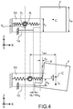
figure 3 est une représentation schématique du capteur desfigures 1 subissant une accélération selon la direction X,et 2 - la
figure 4 est une représentation schématique du capteur desfigures 1 subissant une accélération selon la direction Zet 2 - les
figures 5A à 5E sont des images provenant d'une simulation par éléments finis de la structure desfigures 1 vue de côté et montrant la localisation de l'axe de rotation en fonction de l'épaisseur des poutres de flexion,et 2 - la
figure 6 est une représentation graphique de la variation de la sensibilité transverse ST en fonction de l'épaisseur des poutres de flexion tf, - la
figure 7 est une représentation graphique de la variation de la masse normalisée de la masse inertielle en fonction de l'épaisseur des poutres de flexion tf, - les
figures 8A à 8I sont des représentations schématiques d'étapes d'un exemple de procédé de réalisation d'un capteur à sensibilité maîtrisée, - les
figures 9A à 9K sont des représentations schématiques d'étapes d'un exemple de procédé de réalisation d'un capteur à sensibilité maîtrisée.
- the
Figures 1 and 2 are top and side views respectively of another example of MEMS & NEMS sensor with out-of-plane detection to which the invention applies, - the
figure 3 is a schematic representation of theFigures 1 and 2 undergoing an acceleration in direction X, - the
figure 4 is a schematic representation of theFigures 1 and 2 undergoing acceleration in direction Z - the
Figures 5A to 5E are images from a finite element simulation of the structure ofFigures 1 and 2 side view and showing the location of the axis of rotation as a function of the thickness of the bending beams, - the
figure 6 is a graphic representation of the variation of the transverse sensitivity S T as a function of the thickness of the bending beams t f , - the
figure 7 is a graphic representation of the variation of the normalized mass of the inertial mass as a function of the thickness of the bending beams t f , - the
Figures 8A to 8I are schematic representations of steps of an example of a method for producing a sensor with controlled sensitivity, - the
Figures 9A to 9K are schematic representations of steps of an example of a method for producing a sensor with controlled sensitivity.
La présente invention s'applique aux capteurs inertiels à structure microélectromécanique et nanoélectromécanique ou MEMS&NEMS ou encore M&NEMS, i.e. comportant des éléments de taille micrométrique, tels que la masse et les poutres de suspension de la masse, et des éléments de taille nanométrique, tels que les jauges de contrainte. A des fins de simplicité, on désignera par « capteur microélectromécanique » un capteur comportant à la fois un ou des éléments microélectromécaniques et un ou des éléments nanoélectromécaniques.The present invention applies to inertial sensors with microelectromechanical and nanoelectromechanical structure or MEMS & NEMS or even M & NEMS, ie comprising elements of micrometric size, such as mass and mass suspension beams, and elements of nanometric size, such as strain gauges. For the sake of simplicity, the term “microelectromechanical sensor” will designate a sensor comprising both one or more microelectromechanical elements and one or more nanoelectromechanical elements.
Le plan du capteur est le plan dans lequel s'étend le capteur qui est parallèle au substrat à partir duquel le capteur est fabriqué. Les directions du plan sont désignées X et Y et la direction hors-plan désignée Z est orthogonale au plan du capteur et aux directions X et Y.The sensor plane is the plane in which the sensor extends which is parallel to the substrate from which the sensor is made. The directions of the plane are designated X and Y and the out-of-plane direction designated Z is orthogonal to the plane of the sensor and to the directions X and Y.
En outre les capteurs sont des capteurs inertiels à détection hors-plan, i.e. destinés à détecter une grandeur dans la direction hors-plan Z. Les capteurs comportent au moins une masse qui est destinée à être mise en mouvement dans la direction hors-plan sous l'effet d'une force résultant de la grandeur à détecter, telle que l'accélération, les forces de Coriolis, un champ magnétique, une force....In addition, the sensors are inertial sensors with out-of-plane detection, ie intended to detect a quantity in the out-of-plane direction Z. The sensors include at least one mass which is intended to be set in motion in the out-of-plane direction under the effect of a force resulting from the quantity to be detected, such as acceleration, Coriolis forces, a magnetic field, a force ...
La présente invention permet de réaliser des capteurs M&NEMS à détection hors-plan présentant une sensibilité transverse maîtrisée. On entend par « sensibilité transverse » ou « sensibilité parasite », la sensibilité du capteur, i.e. la sensibilité des moyens de détection, à une grandeur selon une direction orthogonale à la direction hors-plan Z et à la direction dans le plan autour de laquelle la masse est articulée, cette direction est désignée X. On désignera par « sensibilité » la sensibilité du capteur à détection hors-plan, à la grandeur dans la direction hors-plan, i.e. à la grandeur à détecter pour laquelle le capteur est conçu.The present invention makes it possible to produce M & NEMS sensors with out-of-plane detection having controlled transverse sensitivity. The term “transverse sensitivity” or “parasitic sensitivity” means the sensitivity of the sensor, ie the sensitivity of the detection means, to a quantity in a direction orthogonal to the out-of-plane direction Z and to the direction in the plane around which the mass is articulated, this direction is designated X. The sensitivity of the sensor for detection out-of-plane, to the magnitude in the direction out- plane, ie the quantity to be detected for which the sensor is designed.
Sur les
Le capteur comporte un support 2 s'étendant dans un plan XY, une masse 4 suspendue par rapport au support 2 de sorte à être mobile par rapport au support dans la direction hors-plan Z.The sensor comprises a
La masse 4 est suspendue au support 2 par des moyens d'articulation 6 en rotation.The
Les moyens d'articulation 6 comportent, dans l'exemple représenté, deux poutres 8 s'étendant dans la direction Y. Chaque poutre 8 est d'une part ancrée, par une première extrémité longitudinale, à la masse et, par une deuxième extrémité longitudinale, au support. Les poutres 8 sont destinées à se déformer en torsion, lorsque la masse est mise en mouvement. Les poutres 8 assurent un maintien dans la direction Y.The articulation means 6 comprise, in the example shown, two
Les moyens d'articulation comportent également deux deuxièmes poutres 10 s'étendant orthogonalement à l'axe Y et ancrées par une première extrémité à la masse et par une deuxième extrémité au support. Les deuxièmes poutres 10 sont destinées à être sollicitées en flexion.The articulation means also comprise two
Lorsque la masse est soumise à une contrainte selon Z, elle se déplace en rotation par rapport au support 2 autour d'un premier axe pivot Y1 parallèle à la direction Y. Lorsque la masse 4 est soumise à une contrainte selon X, elle se déplace en rotation par rapport au support autour d'un deuxième axe pivot Y2 parallèle la direction Y.When the mass is subjected to a stress along Z, it moves in rotation relative to the
Le capteur comporte également des moyens de détection 12 du déplacement de la masse, comprenant au moins une jauge de contrainte 14 suspendue entre la masse et le support de sorte à subir une contrainte en traction ou de compression, lorsque la masse se déplace autour de l'axe Y1. De manière préférée, les moyens de détection 12 comportent deux jauges de contrainte 14 montées en différentiel de sorte que, lorsqu'une jauge est sollicitée en traction, l'autre jauge est sollicitée en compression.The sensor also comprises means 12 for detecting the displacement of the mass, comprising at least one
Les jauges de contrainte sont par exemple des jauges piézorésistives ou piézoélectriques.The strain gauges are for example piezoresistive or piezoelectric gauges.
Dans l'exemple représenté, les jauges sont disposées en alignement de la face des poutres de flexion 10 et de la masse en regard du support.In the example shown, the gauges are arranged in alignment with the face of the bending beams 10 and the mass opposite the support.
Les emplacements du premier axe pivot Y1 et du deuxième axe pivot Y2 dépendent des raideurs des poutres de flexion et des jauges et de leur épaisseur.The locations of the first pivot axis Y1 and of the second pivot axis Y2 depend on the stiffnesses of the bending beams and of the gauges and on their thickness.
Sur les
Grâce à l'invention, les deuxièmes poutres sollicitées en flexion et la masse sont dimensionnées de sorte que la sensibilité transverse ST ou sensibilité parasite soit maîtrisée.Thanks to the invention, the second beams subjected to bending and the mass are dimensioned so that the transverse sensitivity S T or parasitic sensitivity is controlled.
Les inventeurs ont déterminé qu'une relation pouvait être établie entre l'épaisseur de la masse, l'épaisseur des poutres sollicitées en flexion et la sensibilité parasite, pour réaliser une structure de capteur présentant une sensibilité parasite de valeur donnée, qui peut être nulle.The inventors have determined that a relationship can be established between the thickness of the mass, the thickness of the beams subjected to bending and the parasitic sensitivity, in order to produce a sensor structure having a parasitic sensitivity of given value, which may be zero. .
Sur la
Θ est l'angle de rotation de la masse par rapport au plan YZ et δx est le déplacement de la masse dans la direction X sous l'effet de l'accélération γx. La translation de la mase est exprimée au milieu des poutres de flexionsΘ is the angle of rotation of the mass with respect to the plane YZ and δx is the displacement of the mass in the direction X under the effect of the acceleration γ x . The translation of the base is expressed in the middle of the bending beams
Les poutres de torsion engendrent une raideur hors plan telle que le déplacement en Z est considéré négligeable. Inversement, leur raideur en X est considérée négligeable et elles ne seront pas prises en compte dans le bilan des forces ci-dessous.The torsion beams generate an out-of-plane stiffness such that the displacement in Z is considered negligible. Conversely, their stiffness in X is considered negligible and they will not be taken into account in the balance of forces below.
On se place dans le cas où θ est petit.We place ourselves in the case where θ is small.
Dans le cas où θ est grand, les expressions seraient différentes mais la relation entre les épaisseurs de la masse et des poutres de flexion est la même.In the case where θ is large, the expressions would be different but the relation between the thicknesses of the mass and the bending beams is the same.
Lorsque la structure est soumise à une accélération γx suivant la direction X, elle est soumise aux forces suivantes :
- Une force d'inertie : Fi = mγx ,
- m étant la masse de la masse inertielle.
- A force of inertia: F i = mγ x ,
- m being the mass of the inertial mass.
Une force de rappel des poutres de flexion appliquée par les poutres de flexion : Frf = kfδx , avec kf la raideur des deux poutres 14'.A restoring force of the bending beams applied by the bending beams: F rf = k f δ x , with k f the stiffness of the two beams 14 '.
Une force de rappel de la jauge : Frg = kg (δx + θdg ), avec kg la raideur de la jauge.A return force of the gauge: F rg = k g ( δx + θd g ), with k g the stiffness of the gauge.
dg est la distance entre le milieu des poutres de flexion et le plan milieu XY des jauges, dans la direction Z.d g is the distance between the midpoint of the bending beams and the midplane XY of the gauges, in the direction Z.
En écrivant l'équilibre des forces et l'équilibre des moments au point A, on obtient le système : ![]()
![]()
![]()
![]()
Avec CS la constante de rappel en rotation (ou raideur angulaire) des poutres de flexion, et t la distance entre les deux plans XY contenant respectivement le centre de gravité C de la masse et le premier axe de rotation Y1. Il est à noter que dans le cas de la structure représentée sur les
Du système d'équation (1), on calcule l'expression de l'allongement de la jauge lorsque la structure est soumise à une accélération suivant l'axe X : 
On calcule ensuite la force exercée sur la jauge, qui est égale au produit de sa raideur par son allongement : 
Sur la
Le bilan des forces et des moments s'écrit alors : ![]()
![]()
![]()
![]()
Avec larm : distance dans le plan entre le centre de gravité C de la masse sismique et le centre des poutres de flexion projeté sur X. La valeur de larm est fixée lors de la conception du capteur, les dimensions du capteur dans le plan étant fixées. Puisque l'on travaille en petits signaux, l'allongement des poutres de flexion est négligeable lors du déplacement de la masse. 
La sensibilité transverse ST s'exprime généralement en pourcentage de la sensibilité axiale.The transverse sensitivity S T is generally expressed as a percentage of the axial sensitivity.
On définit alors la sensibilité transverse par : 
Avec ![]()
![]()
Le modèle de poutre de Bernoulli permet d'exprimer les raideurs en fonction du module de Young et de leur géométrie: 
La distance pivot jauge peut elle aussi être exprimée en fonction de la géométrie des poutres ![]()
![]()
D'où : ![]()
![]()
Ainsi, la sensibilité transverse ne dépend que du bras de levier de la structure et du rapport des épaisseurs de la masse et des bras de flexion.Thus, the transverse sensitivity depends only on the lever arm of the structure and the ratio of the thicknesses of the mass and the flexion arms.
Cette sensibilité transverse s'annule pour ![]()
![]()
Généralement, des spécifications en termes de sensibilité transverse sont fixées pour chaque modèle de capteur.Generally, specifications in terms of transverse sensitivity are fixed for each sensor model.
Grâce à l'invention, connaissant la valeur de ST spécifiée il est possible de définir quelles sont les épaisseurs des poutres de flexion et de la masse à choisir, pour obtenir un capteur de sensibilité ST.Thanks to the invention, knowing the value of S T specified it is possible to define what are the thicknesses of the bending beams and the mass to be chosen, in order to obtain a sensitivity sensor S T.
En effet, à partir de la relation (2), on peut écrire : ![]()
![]()
A titre d'exemple, la spécification sur la sensibilité transverse maximale est en général inférieure à 1 %. Ainsi, pour STmax = +/-0.5%, tM = 20 µm et larm = 246µm, on peut déterminer tf. ![]()
![]()
Sur la
On constate un bon accord entre le modèle analytique établi par les inventeurs et la simulation par éléments finis. La sensibilité ST s'annule pour tf = 14,6 µm.There is good agreement between the analytical model established by the inventors and the finite element simulation. The sensitivity S T is canceled out for t f = 14.6 µm.
Sur les
Les
On voit sur ces figures que le deuxième axe de rotation Y2 se rapproche du plan contenant les jauges et est contenu dans ce plan pour une épaisseur des poutres de flexion égale à 14,6 µm. Pour cette épaisseur, l'axe Y2 est dans la plan milieu des jauge, la somme des contraintes selon X est nulle, la sensibilité transverse ST est nulle.It can be seen in these figures that the second axis of rotation Y2 approaches the plane containing the gauges and is contained in this plane for a thickness of the bending beams equal to 14.6 μm. For this thickness, the axis Y2 is in the middle plane of the gauges, the sum of the constraints along X is zero, the transverse sensitivity S T is zero.
Il est à noter que la sensibilité S du capteur à détection hors-plan, i.e. sa sensibilité selon la direction Z, diminue avec l'augmentation de l'épaisseur des poutres de flexion, puisque leur rigidité augmente. Il est possible de compenser cette baisse de sensibilité en augmentant la masse sismique. Cette augmentation est obtenue soit en augmentant la surface de la masse, i.e. ses dimensions dans le plan et/ou en utilisant un matériau plus dense.It should be noted that the sensitivity S of the out-of-plane detection sensor, i.e. its sensitivity in the direction Z, decreases with the increase in the thickness of the bending beams, since their rigidity increases. It is possible to compensate for this drop in sensitivity by increasing the seismic mass. This increase is obtained either by increasing the surface of the mass, i.e. its dimensions in the plane and / or by using a denser material.
Sur la
Des exemples de procédé de réalisation de capteur à détection hors-plan à sensibilité transverse maîtrisée vont maintenant être décrits.Examples of a method for producing an out-of-plane detection sensor with controlled transverse sensitivity will now be described.
Lors de la conception du capteur, la sensibilité transverse ST souhaitée est fixée et les dimensions de la structure, notamment l'épaisseur de la masse et des poutres de flexion sont déterminée. On cherche donc à réaliser un capteur avec une masse d'épaisseur tM et une ou des poutres de flexion d'épaisseur tf tels que la relation (3) soit vérifiée.When designing the sensor, the desired transverse sensitivity S T is fixed and the dimensions of the structure, in particular the thickness of the mass and of the bending beams are determined. We therefore seek to produce a sensor with a mass of thickness t M and one or more bending beams of thickness t f such that relation (3) is verified.
Sur les
On utilise un substrat silicium sur isolant 100 ou SOI (Silicon on Insulate en terminologie anglo-saxonne) comportant une couche de silicium support 102, une couche d'isolant électrique 104 et une couche de silicium 106.A silicon on
Le substrat 100 est représenté sur la
Lors d'une première étape, on réalise les jauges de contrainte. Par exemple, on réalise une implantation du silicium de la couche 106 afin d'ajuster la résistance et le coefficient piézorésistif des jauges. Ensuite la couche 106 est structurée pour former les jauges, par exemple par photolithographie et gravure. Les jauges 14 ont des dimensions nanométriques.During a first step, the strain gauges are produced. For example, an implantation of the silicon of the
L'élément ainsi obtenu est représenté sur la
Lors d'une étape suivante, on protège les jauges, par exemple par le dépôt d'une couche d'oxyde 107, par exemple une couche d'oxyde de silicium.In a following step, the gauges are protected, for example by the deposition of an
L'élément ainsi obtenu est représenté sur la
Lors d'une étape suivante, on forme une couche de silicium 108 sur la couche de silicium 106 afin d'obtenir une épaisseur de silicium égale à l'épaisseur souhaitée tM de la masse, i.e. la somme de l'épaisseur de la couche 106 et celle de la couche 108 égale à tM. L'épaisseur de la couche 106 est par exemple comprise entre 0,1 µm et 1 µm et l'épaisseur de la couche 108 est par exemple comprise entre 1 µm et 2µm. De préférence, la couche 108 est formée par épitaxie. De préférence, les matériaux des couches 106 et 108 sont les mêmes.During a following step, a
En variante, la couche 108 est formée par collage moléculaire d'un substrat, par exemple silicium, suivi d'un amincissement.As a variant, the
L'élément ainsi obtenu est représenté sur la
Lors d'une étape suivante, on réalise un premier masque M1, par exemple en oxyde, destiné à définir la structure, notamment la masse 4, et un deuxième masque M2, par exemple en résine sur l'emplacement de la ou des poutres de flexion.During a following step, a first mask M1 is produced, for example made of oxide, intended to define the structure, in particular the
L'élément ainsi obtenu est représenté sur la
Lors d'une étape suivante, on structure les couches de silicium des couches 106 et 108 pour former la structure, notamment la masse, et pour accéder aux jauges, par exemple par gravure profonde, par exemple par gravure ionique réactive profonde ou DRIE (Deep Reactive Ion Etching en terminologie anglo-saxonne).During a following step, the silicon layers of the
L'élément ainsi obtenu est représenté sur la
Lors d'une étape suivante, on retire le deuxième masque M2.In a next step, the second mask M2 is removed.
L'élément ainsi obtenu est représenté sur la
Lors d'une étape suivante, on amincit la couche 108 au niveau de l'emplacement de la ou des poutres de flexion, i.e. au droit de l'emplacement du deuxième masque M2. La couche 108 est amincie jusqu'à ce que l'épaisseur totale de la couche 106 et de la couche 108 amincie soit égale à la valeur tf déterminée lors la conception du capteur à partir de la relation (3) pour une valeur de sensibilité transverse donnée.During a following step, the
L'amincissement est au temps par exemple par gravure ionique réactive profonde ou DRIE (Deep Reactive Ion Etching en terminologie anglo-saxonne). Le temps d'amincissements est calibré.Thinning is over time, for example by deep reactive ion etching or DRIE (Deep Reactive Ion Etching in English terminology). The thinning time is calibrated.
L'élément ainsi obtenu est représenté sur la
Lors d'une étape suivante, on libère la structure en retirant la couche d'oxyde 104 sous la masse, les poutres et les jauges, le premier masque M1 et la couche de protection 107 des jauges sont avantageusement retirés simultanément. La libération est par exemple réalisée par gravure HF.During a following step, the structure is freed by removing the
L'élément ainsi obtenu est représenté sur la
Sur les
On utilise un substrat silicium sur isolant 200 ou SOI (Silicon on Insulate en terminologie anglo-saxonne) comportant une couche de silicium support 202, une couche d'isolant électrique 204 et une couche de silicium 206.A silicon on
Le substrat 200 est représenté sur la
Lors d'une première étape, on réalise les jauges de contrainte. Par exemple, on réalise une implantation du silicium de la couche 206 afin d'ajuster la résistance et le coefficient piézorésistif des jauges. Ensuite la couche 206 est structurée pour former les jauges, par exemple par photolithographie et gravure. Les jauges 14' ont des dimensions nanométriques.During a first step, the strain gauges are produced. For example, an implantation of the silicon of the
L'élément ainsi obtenu est représenté sur la
Lors d'une étape suivante, on protège les jauges, par exemple par le dépôt d'une couche d'oxyde 207, par exemple une couche d'oxyde de silicium.In a following step, the gauges are protected, for example by the deposition of an
L'élément ainsi obtenu est représenté sur la
Lors d'une étape suivante, on forme une couche de silicium 208 sur la couche 206 de sorte que l'épaisseur formée par la couche 206 et de la couche 208 soit égale à l'épaisseur tf souhaitée. La couche 208 est formée par exemple par épitaxie.During a following step, a
L'élément ainsi obtenu est représenté sur la
Lors d'une étape suivante, on forme une couche d'arrêt, par exemple une couche d'oxyde et ensuite on la structure, par exemple par gravure, de sorte à ne conserver qu'une portion d'arrêt 210 à l'aplomb de l'emplacement de la ou des poutres de flexion. La couche d'oxyde est similaire à la couche d'oxyde 207 formée pour protéger les jauges.In a following step, a stop layer is formed, for example an oxide layer, and then it is structured, for example by etching, so as to keep only a
L'élément ainsi obtenu est représenté sur la
Lors d'une étape suivante, on forme une couche de silicium 212 sur la couche de silicium 208 et sur la portion d'arrêt Z10, par exemple par épitaxie. L'épaisseur de la couche 212 est telle que la somme des épaisseurs de couches 206, 208 et 112 est égale à l'épaisseur tM de la masse souhaitée.During a following step, a
L'élément ainsi obtenu est représenté sur la
Lors d'une étape suivante, on réalise un premier masque M1', par exemple en oxyde, destiné à définir la structure, notamment la masse, et un deuxième masque M2', par exemple en résine sur l'emplacement de la ou des poutres de flexion.During a following step, a first mask M1 ′, for example made of oxide, intended to define the structure, in particular the mass, is produced, and a second mask M2 ′, for example made of resin, on the location of the beam (s) bending.
L'élément ainsi obtenu est représenté sur la
Lors d'une étape suivante, on structure les couches de silicium des couches 206, 208 et 212 pour former la structure, notamment la masse, et pour accéder aux jauges, par exemple par gravure profonde, par exemple par gravure ionique réactive profonde ou DRIE (Deep Reactive Ion Etching en terminologie anglo-saxonne).In a following step, the silicon layers of the
L'élément ainsi obtenu est représenté sur la
Lors d'une étape suivante, on retire le deuxième masque M2'.In a next step, the second mask M2 'is removed.
L'élément ainsi obtenu est représenté sur la
Lors d'une étape suivante, on grave la couche 212 jusqu'à atteindre la portion d'arrêt 210 au niveau de l'emplacement de la ou des poutres de flexion, i.e. au droit de l'emplacement du deuxième masque M2'.During a following step, the
L'élément ainsi obtenu est représenté sur la
Lors d'une étape suivante, on libère la structure en retirant la couche d'oxyde 204 sous la masse, les poutres et les jauges, le premier masque M1, la couche de protection 207 des jauges et la portion d'arrêt 210 sont avantageusement retirés simultanément. La libération est par exemple réalisée par gravure HF.During a following step, the structure is freed by removing the
L'élément ainsi obtenu est représenté sur la
L'épaisseur de la ou des poutres de flexion est définie plus précisément par le procédé de
La structure peut être réalisée en un autre matériau semi-conducteur que le silicium, elle peut être réalisée par exemple le SiGe, SiC.The structure can be made of another semiconductor material than silicon, it can be made for example of SiGe, SiC.
Il sera également compris que le substrat 100 peut être réalisé lors du procédé de fabrication.It will also be understood that the
Claims (13)
Applications Claiming Priority (1)
| Application Number | Priority Date | Filing Date | Title |
|---|---|---|---|
| FR1859118A FR3086801B1 (en) | 2018-10-02 | 2018-10-02 | MICROELECTRONIC SENSOR WITH OUT-OF-PLANE DETECTION OFFERING CONTROLLED TRANSVERSE SENSITIVITY |
Publications (2)
| Publication Number | Publication Date |
|---|---|
| EP3632838A1 true EP3632838A1 (en) | 2020-04-08 |
| EP3632838B1 EP3632838B1 (en) | 2021-06-30 |
Family
ID=67441148
Family Applications (1)
| Application Number | Title | Priority Date | Filing Date |
|---|---|---|---|
| EP19200873.8A Active EP3632838B1 (en) | 2018-10-02 | 2019-10-01 | Microelectronic sensor with out-of-plane detection providing a controlled cross sensitivity |
Country Status (3)
| Country | Link |
|---|---|
| US (1) | US10968096B2 (en) |
| EP (1) | EP3632838B1 (en) |
| FR (1) | FR3086801B1 (en) |
Families Citing this family (2)
| Publication number | Priority date | Publication date | Assignee | Title |
|---|---|---|---|---|
| FR3098809B1 (en) * | 2019-07-18 | 2021-06-18 | Commissariat Energie Atomique | Mechanical link for MEMS and NEMS mechanical structure, and MEMS and NEMS structure including such a mechanical link |
| US11474126B2 (en) * | 2020-03-05 | 2022-10-18 | Quartz Seismic Sensors, Inc. | High precision rotation sensor and method |
Citations (2)
| Publication number | Priority date | Publication date | Assignee | Title |
|---|---|---|---|---|
| EP2211185A1 (en) | 2009-01-23 | 2010-07-28 | Commissariat à l'Énergie Atomique et aux Énergies Alternatives | Inertial sensor unit or resonant sensor with surface technology, with out-of-plane detection by strain gauge |
| FR3000050A1 (en) | 2012-12-20 | 2014-06-27 | Tronic S Microsystems | MICROELECTROMECHANICAL DEVICE HAVING AT LEAST TWO DEFORMABLE ELEMENTS OF DIFFERENT DIMENSIONS |
Family Cites Families (2)
| Publication number | Priority date | Publication date | Assignee | Title |
|---|---|---|---|---|
| FR2983844B1 (en) * | 2011-12-12 | 2014-08-08 | Commissariat Energie Atomique | PIVOT MECHANICAL BONDING FOR MEMS AND NEMS MECHANICAL STRUCTURES |
| EP2808295B1 (en) * | 2013-05-31 | 2015-12-30 | Tronics Microsystems S.A. | MEMS-Sensor |
-
2018
- 2018-10-02 FR FR1859118A patent/FR3086801B1/en active Active
-
2019
- 2019-10-01 US US16/590,015 patent/US10968096B2/en active Active
- 2019-10-01 EP EP19200873.8A patent/EP3632838B1/en active Active
Patent Citations (2)
| Publication number | Priority date | Publication date | Assignee | Title |
|---|---|---|---|---|
| EP2211185A1 (en) | 2009-01-23 | 2010-07-28 | Commissariat à l'Énergie Atomique et aux Énergies Alternatives | Inertial sensor unit or resonant sensor with surface technology, with out-of-plane detection by strain gauge |
| FR3000050A1 (en) | 2012-12-20 | 2014-06-27 | Tronic S Microsystems | MICROELECTROMECHANICAL DEVICE HAVING AT LEAST TWO DEFORMABLE ELEMENTS OF DIFFERENT DIMENSIONS |
Also Published As
| Publication number | Publication date |
|---|---|
| US10968096B2 (en) | 2021-04-06 |
| US20200102211A1 (en) | 2020-04-02 |
| FR3086801B1 (en) | 2021-01-01 |
| EP3632838B1 (en) | 2021-06-30 |
| FR3086801A1 (en) | 2020-04-03 |
Similar Documents
| Publication | Publication Date | Title |
|---|---|---|
| EP2791048B1 (en) | Mechanical connection forming a pivot for mems and nems mechanical structures | |
| EP2367015B1 (en) | Force sensor with reduced noise | |
| EP2541222B1 (en) | Pressure-measurement device with optimised sensitivity | |
| EP2008965B1 (en) | Resonant device with piezoresistive detection made using surface technologies | |
| EP2491406B1 (en) | Sensor for in-plane piezoresistive detection | |
| EP2343556B1 (en) | Micromechanical structure including a mobile part equipped with stops for out-of-plane movements of the structure, and the method for making said structure | |
| EP2607907B1 (en) | Micro/nano multiaxial inertial motion sensor device | |
| EP2656006B1 (en) | Planar structure for a triaxial gyrometer | |
| EP2065713B1 (en) | Detection device with a hanging piezoresistive strain gauge comprising a strain amplification cell | |
| EP2600104B1 (en) | Inertial micro-sensor of rotational movements | |
| FR2941532A1 (en) | SENSOR DEVICE AND METHOD FOR MANUFACTURING SAME | |
| EP3632838B1 (en) | Microelectronic sensor with out-of-plane detection providing a controlled cross sensitivity | |
| EP3599469B1 (en) | Accelerometer with detection by strain gauge with improved precision | |
| EP3217181B1 (en) | Damped linear accelerometer | |
| EP3722253B1 (en) | Out-of-plane hinge for micromechanical and/or nanomechanical structure with reduced sensitivity to internal constraints | |
| EP3722254B1 (en) | Hinge providing reduced sensitivity to internal constraints | |
| FR3000050A1 (en) | MICROELECTROMECHANICAL DEVICE HAVING AT LEAST TWO DEFORMABLE ELEMENTS OF DIFFERENT DIMENSIONS | |
| FR3024872A1 (en) | MICROELECTROMECHANICAL DEVICE HAVING SENSITIVITY TO OUTSTANDING MECHANICAL SOLICITATION |
Legal Events
| Date | Code | Title | Description |
|---|---|---|---|
| PUAI | Public reference made under article 153(3) epc to a published international application that has entered the european phase |
Free format text: ORIGINAL CODE: 0009012 |
|
| STAA | Information on the status of an ep patent application or granted ep patent |
Free format text: STATUS: REQUEST FOR EXAMINATION WAS MADE |
|
| 17P | Request for examination filed |
Effective date: 20191001 |
|
| AK | Designated contracting states |
Kind code of ref document: A1 Designated state(s): AL AT BE BG CH CY CZ DE DK EE ES FI FR GB GR HR HU IE IS IT LI LT LU LV MC MK MT NL NO PL PT RO RS SE SI SK SM TR |
|
| AX | Request for extension of the european patent |
Extension state: BA ME |
|
| GRAP | Despatch of communication of intention to grant a patent |
Free format text: ORIGINAL CODE: EPIDOSNIGR1 |
|
| STAA | Information on the status of an ep patent application or granted ep patent |
Free format text: STATUS: GRANT OF PATENT IS INTENDED |
|
| INTG | Intention to grant announced |
Effective date: 20210126 |
|
| RIN1 | Information on inventor provided before grant (corrected) |
Inventor name: REY, PATRICE Inventor name: JOET, LOIC |
|
| GRAS | Grant fee paid |
Free format text: ORIGINAL CODE: EPIDOSNIGR3 |
|
| GRAA | (expected) grant |
Free format text: ORIGINAL CODE: 0009210 |
|
| STAA | Information on the status of an ep patent application or granted ep patent |
Free format text: STATUS: THE PATENT HAS BEEN GRANTED |
|
| AK | Designated contracting states |
Kind code of ref document: B1 Designated state(s): AL AT BE BG CH CY CZ DE DK EE ES FI FR GB GR HR HU IE IS IT LI LT LU LV MC MK MT NL NO PL PT RO RS SE SI SK SM TR |
|
| REG | Reference to a national code |
Ref country code: CH Ref legal event code: EP |
|
| REG | Reference to a national code |
Ref country code: AT Ref legal event code: REF Ref document number: 1406218 Country of ref document: AT Kind code of ref document: T Effective date: 20210715 |
|
| REG | Reference to a national code |
Ref country code: DE Ref legal event code: R096 Ref document number: 602019005736 Country of ref document: DE |
|
| REG | Reference to a national code |
Ref country code: IE Ref legal event code: FG4D Free format text: LANGUAGE OF EP DOCUMENT: FRENCH |
|
| REG | Reference to a national code |
Ref country code: LT Ref legal event code: MG9D |
|
| PG25 | Lapsed in a contracting state [announced via postgrant information from national office to epo] |
Ref country code: HR Free format text: LAPSE BECAUSE OF FAILURE TO SUBMIT A TRANSLATION OF THE DESCRIPTION OR TO PAY THE FEE WITHIN THE PRESCRIBED TIME-LIMIT Effective date: 20210630 Ref country code: FI Free format text: LAPSE BECAUSE OF FAILURE TO SUBMIT A TRANSLATION OF THE DESCRIPTION OR TO PAY THE FEE WITHIN THE PRESCRIBED TIME-LIMIT Effective date: 20210630 Ref country code: BG Free format text: LAPSE BECAUSE OF FAILURE TO SUBMIT A TRANSLATION OF THE DESCRIPTION OR TO PAY THE FEE WITHIN THE PRESCRIBED TIME-LIMIT Effective date: 20210930 |
|
| REG | Reference to a national code |
Ref country code: NL Ref legal event code: MP Effective date: 20210630 |
|
| REG | Reference to a national code |
Ref country code: AT Ref legal event code: MK05 Ref document number: 1406218 Country of ref document: AT Kind code of ref document: T Effective date: 20210630 |
|
| PG25 | Lapsed in a contracting state [announced via postgrant information from national office to epo] |
Ref country code: RS Free format text: LAPSE BECAUSE OF FAILURE TO SUBMIT A TRANSLATION OF THE DESCRIPTION OR TO PAY THE FEE WITHIN THE PRESCRIBED TIME-LIMIT Effective date: 20210630 Ref country code: SE Free format text: LAPSE BECAUSE OF FAILURE TO SUBMIT A TRANSLATION OF THE DESCRIPTION OR TO PAY THE FEE WITHIN THE PRESCRIBED TIME-LIMIT Effective date: 20210630 Ref country code: LV Free format text: LAPSE BECAUSE OF FAILURE TO SUBMIT A TRANSLATION OF THE DESCRIPTION OR TO PAY THE FEE WITHIN THE PRESCRIBED TIME-LIMIT Effective date: 20210630 Ref country code: NO Free format text: LAPSE BECAUSE OF FAILURE TO SUBMIT A TRANSLATION OF THE DESCRIPTION OR TO PAY THE FEE WITHIN THE PRESCRIBED TIME-LIMIT Effective date: 20210930 Ref country code: GR Free format text: LAPSE BECAUSE OF FAILURE TO SUBMIT A TRANSLATION OF THE DESCRIPTION OR TO PAY THE FEE WITHIN THE PRESCRIBED TIME-LIMIT Effective date: 20211001 |
|
| PG25 | Lapsed in a contracting state [announced via postgrant information from national office to epo] |
Ref country code: SK Free format text: LAPSE BECAUSE OF FAILURE TO SUBMIT A TRANSLATION OF THE DESCRIPTION OR TO PAY THE FEE WITHIN THE PRESCRIBED TIME-LIMIT Effective date: 20210630 Ref country code: ES Free format text: LAPSE BECAUSE OF FAILURE TO SUBMIT A TRANSLATION OF THE DESCRIPTION OR TO PAY THE FEE WITHIN THE PRESCRIBED TIME-LIMIT Effective date: 20210630 Ref country code: EE Free format text: LAPSE BECAUSE OF FAILURE TO SUBMIT A TRANSLATION OF THE DESCRIPTION OR TO PAY THE FEE WITHIN THE PRESCRIBED TIME-LIMIT Effective date: 20210630 Ref country code: AT Free format text: LAPSE BECAUSE OF FAILURE TO SUBMIT A TRANSLATION OF THE DESCRIPTION OR TO PAY THE FEE WITHIN THE PRESCRIBED TIME-LIMIT Effective date: 20210630 Ref country code: CZ Free format text: LAPSE BECAUSE OF FAILURE TO SUBMIT A TRANSLATION OF THE DESCRIPTION OR TO PAY THE FEE WITHIN THE PRESCRIBED TIME-LIMIT Effective date: 20210630 Ref country code: RO Free format text: LAPSE BECAUSE OF FAILURE TO SUBMIT A TRANSLATION OF THE DESCRIPTION OR TO PAY THE FEE WITHIN THE PRESCRIBED TIME-LIMIT Effective date: 20210630 Ref country code: NL Free format text: LAPSE BECAUSE OF FAILURE TO SUBMIT A TRANSLATION OF THE DESCRIPTION OR TO PAY THE FEE WITHIN THE PRESCRIBED TIME-LIMIT Effective date: 20210630 Ref country code: PT Free format text: LAPSE BECAUSE OF FAILURE TO SUBMIT A TRANSLATION OF THE DESCRIPTION OR TO PAY THE FEE WITHIN THE PRESCRIBED TIME-LIMIT Effective date: 20211102 Ref country code: SM Free format text: LAPSE BECAUSE OF FAILURE TO SUBMIT A TRANSLATION OF THE DESCRIPTION OR TO PAY THE FEE WITHIN THE PRESCRIBED TIME-LIMIT Effective date: 20210630 |
|
| PG25 | Lapsed in a contracting state [announced via postgrant information from national office to epo] |
Ref country code: PL Free format text: LAPSE BECAUSE OF FAILURE TO SUBMIT A TRANSLATION OF THE DESCRIPTION OR TO PAY THE FEE WITHIN THE PRESCRIBED TIME-LIMIT Effective date: 20210630 |
|
| REG | Reference to a national code |
Ref country code: DE Ref legal event code: R097 Ref document number: 602019005736 Country of ref document: DE |
|
| PG25 | Lapsed in a contracting state [announced via postgrant information from national office to epo] |
Ref country code: DK Free format text: LAPSE BECAUSE OF FAILURE TO SUBMIT A TRANSLATION OF THE DESCRIPTION OR TO PAY THE FEE WITHIN THE PRESCRIBED TIME-LIMIT Effective date: 20210630 |
|
| PLBE | No opposition filed within time limit |
Free format text: ORIGINAL CODE: 0009261 |
|
| STAA | Information on the status of an ep patent application or granted ep patent |
Free format text: STATUS: NO OPPOSITION FILED WITHIN TIME LIMIT |
|
| PG25 | Lapsed in a contracting state [announced via postgrant information from national office to epo] |
Ref country code: AL Free format text: LAPSE BECAUSE OF FAILURE TO SUBMIT A TRANSLATION OF THE DESCRIPTION OR TO PAY THE FEE WITHIN THE PRESCRIBED TIME-LIMIT Effective date: 20210630 |
|
| 26N | No opposition filed |
Effective date: 20220331 |
|
| REG | Reference to a national code |
Ref country code: BE Ref legal event code: MM Effective date: 20211031 |
|
| PG25 | Lapsed in a contracting state [announced via postgrant information from national office to epo] |
Ref country code: MC Free format text: LAPSE BECAUSE OF FAILURE TO SUBMIT A TRANSLATION OF THE DESCRIPTION OR TO PAY THE FEE WITHIN THE PRESCRIBED TIME-LIMIT Effective date: 20210630 |
|
| PG25 | Lapsed in a contracting state [announced via postgrant information from national office to epo] |
Ref country code: LU Free format text: LAPSE BECAUSE OF NON-PAYMENT OF DUE FEES Effective date: 20211001 Ref country code: BE Free format text: LAPSE BECAUSE OF NON-PAYMENT OF DUE FEES Effective date: 20211031 |
|
| PG25 | Lapsed in a contracting state [announced via postgrant information from national office to epo] |
Ref country code: IE Free format text: LAPSE BECAUSE OF NON-PAYMENT OF DUE FEES Effective date: 20211001 |
|
| PG25 | Lapsed in a contracting state [announced via postgrant information from national office to epo] |
Ref country code: LT Free format text: LAPSE BECAUSE OF FAILURE TO SUBMIT A TRANSLATION OF THE DESCRIPTION OR TO PAY THE FEE WITHIN THE PRESCRIBED TIME-LIMIT Effective date: 20210630 |
|
| REG | Reference to a national code |
Ref country code: CH Ref legal event code: PL |
|
| PG25 | Lapsed in a contracting state [announced via postgrant information from national office to epo] |
Ref country code: CY Free format text: LAPSE BECAUSE OF FAILURE TO SUBMIT A TRANSLATION OF THE DESCRIPTION OR TO PAY THE FEE WITHIN THE PRESCRIBED TIME-LIMIT Effective date: 20210630 |
|
| PG25 | Lapsed in a contracting state [announced via postgrant information from national office to epo] |
Ref country code: LI Free format text: LAPSE BECAUSE OF NON-PAYMENT OF DUE FEES Effective date: 20221031 Ref country code: HU Free format text: LAPSE BECAUSE OF FAILURE TO SUBMIT A TRANSLATION OF THE DESCRIPTION OR TO PAY THE FEE WITHIN THE PRESCRIBED TIME-LIMIT; INVALID AB INITIO Effective date: 20191001 Ref country code: CH Free format text: LAPSE BECAUSE OF NON-PAYMENT OF DUE FEES Effective date: 20221031 |
|
| PGFP | Annual fee paid to national office [announced via postgrant information from national office to epo] |
Ref country code: GB Payment date: 20231025 Year of fee payment: 5 |
|
| PGFP | Annual fee paid to national office [announced via postgrant information from national office to epo] |
Ref country code: IT Payment date: 20231031 Year of fee payment: 5 Ref country code: FR Payment date: 20231023 Year of fee payment: 5 Ref country code: DE Payment date: 20231018 Year of fee payment: 5 |
|
| PG25 | Lapsed in a contracting state [announced via postgrant information from national office to epo] |
Ref country code: MK Free format text: LAPSE BECAUSE OF FAILURE TO SUBMIT A TRANSLATION OF THE DESCRIPTION OR TO PAY THE FEE WITHIN THE PRESCRIBED TIME-LIMIT Effective date: 20210630 |
|
| PG25 | Lapsed in a contracting state [announced via postgrant information from national office to epo] |
Ref country code: TR Free format text: LAPSE BECAUSE OF FAILURE TO SUBMIT A TRANSLATION OF THE DESCRIPTION OR TO PAY THE FEE WITHIN THE PRESCRIBED TIME-LIMIT Effective date: 20210630 |
|
| PG25 | Lapsed in a contracting state [announced via postgrant information from national office to epo] |
Ref country code: MT Free format text: LAPSE BECAUSE OF FAILURE TO SUBMIT A TRANSLATION OF THE DESCRIPTION OR TO PAY THE FEE WITHIN THE PRESCRIBED TIME-LIMIT Effective date: 20210630 |