EP3722253B1 - Out-of-plane hinge for micromechanical and/or nanomechanical structure with reduced sensitivity to internal constraints - Google Patents
Out-of-plane hinge for micromechanical and/or nanomechanical structure with reduced sensitivity to internal constraints Download PDFInfo
- Publication number
- EP3722253B1 EP3722253B1 EP20168233.3A EP20168233A EP3722253B1 EP 3722253 B1 EP3722253 B1 EP 3722253B1 EP 20168233 A EP20168233 A EP 20168233A EP 3722253 B1 EP3722253 B1 EP 3722253B1
- Authority
- EP
- European Patent Office
- Prior art keywords
- bending
- torsion
- support
- movable part
- hinge
- Prior art date
- Legal status (The legal status is an assumption and is not a legal conclusion. Google has not performed a legal analysis and makes no representation as to the accuracy of the status listed.)
- Active
Links
- 230000035945 sensitivity Effects 0.000 title description 3
- 238000005452 bending Methods 0.000 claims description 61
- 238000006073 displacement reaction Methods 0.000 claims description 11
- 238000004377 microelectronic Methods 0.000 claims description 8
- 238000001514 detection method Methods 0.000 claims description 7
- XUIMIQQOPSSXEZ-UHFFFAOYSA-N Silicon Chemical compound [Si] XUIMIQQOPSSXEZ-UHFFFAOYSA-N 0.000 description 10
- 230000000694 effects Effects 0.000 description 10
- 238000004519 manufacturing process Methods 0.000 description 10
- 238000004873 anchoring Methods 0.000 description 9
- 239000000758 substrate Substances 0.000 description 9
- 238000005530 etching Methods 0.000 description 8
- 229910052710 silicon Inorganic materials 0.000 description 7
- 239000010703 silicon Substances 0.000 description 7
- 230000015572 biosynthetic process Effects 0.000 description 4
- 238000000407 epitaxy Methods 0.000 description 4
- 238000000034 method Methods 0.000 description 4
- KRHYYFGTRYWZRS-UHFFFAOYSA-N Fluorane Chemical compound F KRHYYFGTRYWZRS-UHFFFAOYSA-N 0.000 description 3
- 101100460147 Sarcophaga bullata NEMS gene Proteins 0.000 description 3
- 238000000151 deposition Methods 0.000 description 2
- 230000008021 deposition Effects 0.000 description 2
- 239000002019 doping agent Substances 0.000 description 2
- 238000002513 implantation Methods 0.000 description 2
- 239000012212 insulator Substances 0.000 description 2
- 229910021421 monocrystalline silicon Inorganic materials 0.000 description 2
- ZOXJGFHDIHLPTG-UHFFFAOYSA-N Boron Chemical group [B] ZOXJGFHDIHLPTG-UHFFFAOYSA-N 0.000 description 1
- VYPSYNLAJGMNEJ-UHFFFAOYSA-N Silicium dioxide Chemical compound O=[Si]=O VYPSYNLAJGMNEJ-UHFFFAOYSA-N 0.000 description 1
- 230000001133 acceleration Effects 0.000 description 1
- 230000006978 adaptation Effects 0.000 description 1
- 238000000429 assembly Methods 0.000 description 1
- 230000000712 assembly Effects 0.000 description 1
- 230000006835 compression Effects 0.000 description 1
- 238000007906 compression Methods 0.000 description 1
- 239000013078 crystal Substances 0.000 description 1
- 230000010354 integration Effects 0.000 description 1
- 238000005259 measurement Methods 0.000 description 1
- 238000000206 photolithography Methods 0.000 description 1
- 230000035939 shock Effects 0.000 description 1
- 229910052814 silicon oxide Inorganic materials 0.000 description 1
Images

Classifications
-
- F—MECHANICAL ENGINEERING; LIGHTING; HEATING; WEAPONS; BLASTING
- F16—ENGINEERING ELEMENTS AND UNITS; GENERAL MEASURES FOR PRODUCING AND MAINTAINING EFFECTIVE FUNCTIONING OF MACHINES OR INSTALLATIONS; THERMAL INSULATION IN GENERAL
- F16C—SHAFTS; FLEXIBLE SHAFTS; ELEMENTS OR CRANKSHAFT MECHANISMS; ROTARY BODIES OTHER THAN GEARING ELEMENTS; BEARINGS
- F16C11/00—Pivots; Pivotal connections
- F16C11/04—Pivotal connections
- F16C11/12—Pivotal connections incorporating flexible connections, e.g. leaf springs
-
- B—PERFORMING OPERATIONS; TRANSPORTING
- B81—MICROSTRUCTURAL TECHNOLOGY
- B81B—MICROSTRUCTURAL DEVICES OR SYSTEMS, e.g. MICROMECHANICAL DEVICES
- B81B3/00—Devices comprising flexible or deformable elements, e.g. comprising elastic tongues or membranes
- B81B3/0035—Constitution or structural means for controlling the movement of the flexible or deformable elements
- B81B3/0051—For defining the movement, i.e. structures that guide or limit the movement of an element
-
- G—PHYSICS
- G01—MEASURING; TESTING
- G01L—MEASURING FORCE, STRESS, TORQUE, WORK, MECHANICAL POWER, MECHANICAL EFFICIENCY, OR FLUID PRESSURE
- G01L1/00—Measuring force or stress, in general
- G01L1/18—Measuring force or stress, in general using properties of piezo-resistive materials, i.e. materials of which the ohmic resistance varies according to changes in magnitude or direction of force applied to the material
- G01L1/183—Measuring force or stress, in general using properties of piezo-resistive materials, i.e. materials of which the ohmic resistance varies according to changes in magnitude or direction of force applied to the material by measuring variations of frequency of vibrating piezo-resistive material
-
- B—PERFORMING OPERATIONS; TRANSPORTING
- B81—MICROSTRUCTURAL TECHNOLOGY
- B81B—MICROSTRUCTURAL DEVICES OR SYSTEMS, e.g. MICROMECHANICAL DEVICES
- B81B2203/00—Basic microelectromechanical structures
- B81B2203/01—Suspended structures, i.e. structures allowing a movement
- B81B2203/0145—Flexible holders
- B81B2203/0154—Torsion bars
-
- B—PERFORMING OPERATIONS; TRANSPORTING
- B81—MICROSTRUCTURAL TECHNOLOGY
- B81B—MICROSTRUCTURAL DEVICES OR SYSTEMS, e.g. MICROMECHANICAL DEVICES
- B81B2203/00—Basic microelectromechanical structures
- B81B2203/01—Suspended structures, i.e. structures allowing a movement
- B81B2203/0145—Flexible holders
- B81B2203/0163—Spring holders
Definitions
- the present invention relates to an out-of-plane hinge for a micro and / or nanomechanical structure, in particular for a microelectromechanical system, offering reduced sensitivity to internal stresses.
- microelectromechanical systems or MEMS microelectromechanical systems in English terminology
- micro and nanoelectromechanical systems or M & NEMS systems micro & nanoelectromechanical systems in English terminology
- MEMS microelectromechanical systems in English terminology
- M & NEMS systems micro & nanoelectromechanical systems in English terminology
- MEMS microelectromechanical systems in English terminology
- M & NEMS systems micro & nanoelectromechanical systems in English terminology
- the moving element is moved for example by means of electrostatic forces, for example to move a micromirror.
- the mobile element is suspended with respect to the substrate and depending on the applications we may wish it to have a displacement in the plane of the system or an out-of-plane displacement, i.e. orthogonally to the plane of the system.
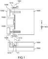
- the structure extending in the XY plane comprises a mass 1000 capable of moving in a direction outside the Z plane relative to a support 1002.
- the structure comprises a hinge 1004 forming a rotational articulation 1004 between the support 1002 and the support 1002. mass 1000, the hinge having an axis of rotation Y1 in the plane.
- the hinge connects an edge of the mass to the support, and comprises two beams 1006 intended to be biased in torsion and coaxial with the axis of rotation and two beams 1008 intended to be biased in bending and orthogonal to the axis of rotation.
- the beams 1006 and 1008 connect the mass to the support.
- This structure also has two gauges piezoresistive 1010 for measuring the displacement of the mass.
- the function of the bending beams 1008 is to stiffen the articulation in the X direction. However, they also cause a stiffening of the articulation in the out-of-plane direction, which is not desirable. In order to reduce their effect on the stiffness in the Z direction, the thickness of the bending beams is reduced.
- Such a structure is produced by the methods of microelectronics implementing deposits, etchings and a release of the mass.
- the structure is produced by etching in a layer formed by epitaxy on a Silicon on Insulator or SOI (Silicon on Insulate) substrate and the mass is released by etching the buried oxide layer of the SOI substrate.
- SOI Silicon on Insulator
- stresses are generated in the layer. These constraints can in particular be due to doping. For example, boron atoms are smaller than silicon atoms and induce compressive stress in the crystal lattice of silicon. This constraint can also appear before epitaxy, during doping of the thin layer of the SOI substrate. When the structure is released by etching, these stresses in all the layers are at least partially released. However, this release of stresses generates a new balance of forces and moments which can lead to a deformation of the structure. Bending beams are formed in the epitaxial layer. When releasing the structure, the stresses in the beams relax / contract.
- the gauges which are parallel to the bending beams, oppose the expansion / retraction of the bending beams.
- the bending beams and the gauges being in different planes, the mass tilts. It is then no longer perpendicular to the Z axis.
- the gauges 1010 not being aligned, they will induce a torque on the mass and make it rotate in the plane. .
- the internal stresses of the bottom layer of the bending beams cause them to flex, causing the mass to tilt.
- Deformation of the structure can also occur during the release of stresses in the SOI substrate.
- a microelectromechanical structure can include upper and lower stops to limit the out-of-plane travel of the mass, in order to avoid exceeding the admissible stresses.
- the mass When the mass is not inclined, it is at rest at an equal distance from the upper and lower stops. However, in the event of inclination of the mass, the distances between the mass and the upper and lower stops are different. If the mass is inclined towards the support, the distance between the mass and the lower stopper is less than that between the mass and the upper stop. If the inclination of the mass is known, the stops could be adapted to compensate for this difference in distance, but such an adaptation complicates the production process. In addition, it is difficult to predict the inclination of the mass.
- Deformation of the structure can also occur in the absence of strain gauges.
- microelectromechanical micromirror comprising a mirror body mounted to be movable in rotation about an axis of rotation, the axis of rotation being formed by a beam having low torsional rigidity.
- Cantilever-type beams connect the mirror body to the support via springs and provide torsional rigidity around the axis of rotation.
- an out-of-plane hinge for a micro and / or nanomechanical structure which comprises a support, at least one part movable in an out-of-plane direction having the characteristics of claim 1.
- the invention makes it possible to compensate for the effect of the internal stresses released along the direction in the plane orthogonal to the axis of rotation, which are the stresses which have the most troublesome action on the structure.
- Internal stresses in the direction of the axis of rotation can be released, and stresses in the out-of-plane direction add up. But their contributions on the strain of the structure are weak relative to those of the stresses along the direction in the plane orthogonal to the axis of rotation
- the gauges are not very strained, or even are not strained.
- a pivot joint comprising at least one bending element comprising combined bending beams such that self-compensation of the internal stresses takes place within the bending element, limiting the effect of the bending elements. internal stresses on the structure.
- the hinge comprises two flexion elements.
- the structure is implemented in a microelectronic system and comprises detection means, for example comprising one or more strain gauges.
- the detection means comprise two gauges arranged relative to one another so as to limit the effect, on the structure, of the internal stresses of the layer in which they are made.
- the structure comprises torsion elements such that they also limit the effect of the internal stresses of the torsion beams on the structure.
- the subject of the present invention is therefore a hinge for a micromechanical and / or nanomechanical structure as defined by claim 1.
- the at least first and second bending beams have the same dimensions.
- the hinge comprises two flexion elements.
- the bending elements are arranged on either side of the at least one torsion element.
- the hinge comprises two torsion elements each comprising a torsion beam aligned with the axis of rotation.
- the torsion element comprises a first torsion beam and a second torsion beam, and said torsion beam forms the first torsion beam, the first and second torsion beams. torsion being parallel to each other, and interconnected by at least one of their longitudinal ends, one of the torsion beams being intended to be mechanically connected directly to the moving part and the other torsion beam being intended to be mechanically connected directly to the support.
- the hinge comprises two pairs of torsion beams aligned with respect to one another along the axis of rotation.
- the hinge is made from a stack of layers and etching steps, in which at least the first and second bending beams are made in the same layer.
- the present invention also relates to a micromechanical and / nanomechanical structure comprising a support, a part movable in the out-of-plane direction and a hinge according to the invention connecting the movable part to the support.
- the structure may include out-of-plane abutment means for the mass moving away from and / or moving towards the support.
- a subject of the present invention is also a microelectronic system comprising at least one structure according to the invention.
- the microelectronic system can advantageously comprise means for detecting the out-of-plane displacement of the mobile part, comprising at least a first strain gauge, the first strain gauge being mechanically connected directly to the support by a first end and to the mobile part by a second end.
- the means for detecting the out-of-plane displacement of the mobile part also include a second strain gauge, the second strain gauge being mechanically connected directly to the support by a first end and to the mobile part by a second end, the first end and the second end of the first strain gauge and the first end and the second end of the second strain gauge being disposed with respect to each other such that the orientation of the first end towards the second end of the first strain gauge is opposite the orientation of the first end toward the second end of the second strain gauge.
- the present invention relates to hinges for micromechanical and / or nanomechanical structures, in particular implemented in MEMS and / or NEMS systems applied for example to accelerometers, gyrometers, gas sensors, actuators, etc. which will follow the structure will be called MEMS structure.
- FIG. 2 one can see a schematic representation of a MEMS structure comprising an example of a hinge according to a first embodiment.
- the MEMS structure S1 comprises a mobile part M suspended from a support 2 by means of a hinge 4 forming a pivot articulation 4.
- the mobile part M can be an inertial mass in the case of an accelerometer, or a micromirror or an orientable platform in the case of an actuator.
- the mobile part M extends in the plane of the structure defined by the X and Y axes.
- the plane of the structure is the mean plane of the structure which corresponds to the plane of the sheet in the representation of the figure 2 .
- the suspended part is intended to move in an out-of-plane Z direction, orthogonal to the X and Y axes.
- the hinge has a Y1 axis parallel to the Y axis.
- the hinge 4 is connected to an edge of the suspended part M.
- the hinge 4 comprises two beams 6 extending along the axis Y1 and intended to be stressed in torsion during the movement of the mobile mass in the out-of-plane direction.
- Each torsion beam 6 is connected by a longitudinal end to an anchoring stud P of the support, and by another longitudinal end to the mobile part M.
- the hinge also comprises two elements E1 extending perpendicularly to the axis Y1 between the movable part M and the support 2.
- the elements E1 are intended to be stressed in bending and will be referred to hereinafter as “bending elements”.
- the two elements E1 have similar structures, only one of these elements will be described in detail.
- the bending element E1 comprises a pair of first and second beams 12.1, 12.2 mutually parallel and perpendicular to the axis Y1.
- the Y1 axis passes through the middle of the first and second beams.
- Each beam 12.1, 12.2 is connected by a first longitudinal end 12.11, 12.21 to an anchoring stud 14, 16 of the support respectively, and by a second end 12.12, 12.22 to the mobile part M.
- the beams are arranged head-to-tail, iela first end 12.11 of the first beam and the first end 12.21 of the second beam are each arranged on either side of the axis of rotation Y1, as well as the second ends 12.12 and 12.22.
- each beam 12.1, 12.2, which are released during manufacture, are exerted between the first end 12.11, 12.21 connected to the support and the end 12.12, 12.22 connected to the mobile part.
- the head-to-tail arrangement of the beams 12.1, 12.2, and in particular the arrangement of their anchoring to the support, has the consequence that the internal stresses in the direction X in the first beam 12.1 are exerted on the mass in a direction opposite to that in which exerts the internal stresses in the direction X in the second beam 12.2.
- the internal stresses in the direction X at the first beam 12.1 have an action on the mobile part M opposite to that exerted by the second beam 12.2.
- the beams have substantially the same characteristics, ie substantially the same dimensions at the margins due to the production process, and are produced in the same layer, the internal stresses in the X direction in the two beams are close or equal and neutralize each other. almost entirely or entirely.
- the bending element E1 then exerts little or no force on the movable part, it is therefore not deformed under the effect of the relaxation of the internal stresses, or else negligibly.
- the MEMS structure S1 also comprises means 10 for measuring the displacement of the mobile part.
- the measuring means 10 comprise gauges 11 suspended between the mobile part and anchoring studs 18 of the support and are arranged in a plane distinct from a plane parallel to the plane XY and containing the axis of rotation Y1. .
- the gauges 11 are arranged so that, when one gauge is stressed in tension, the other is stressed in compression.
- the bending beams of each bending element are mechanically mounted in parallel.
- the gauges 11, 11 ' are aligned and are connected to the mobile part and to the anchoring pads so that the internal stresses of one gauge oppose the internal stresses of the other gauge.
- the gauge 11 has a longitudinal end 11.1 connected to the mobile part and a longitudinal end 11.2 connected to anchoring stud 36.
- the gauge 11 ' has a longitudinal end 11.1' connected to the mobile part and a longitudinal end 11.2 'connected to a stud anchor 38.
- the longitudinal ends 11.1 and 11.1 ' are opposite.
- the anchoring stud 36 is located in a window 40 formed through the movable part, an upright 42 of which serves to fasten the ends 11.1, 11.1 ′ of the gauges.
- Each bending element can include a set of several bending beams, each set providing self-compensation for internal stresses to its beams.
- the implementation of several beams makes it possible to increase the rigidity in the plane offered by the flexural elements.
- each bending element can include several pairs of bending beams, each pair providing self-compensation for internal stresses to its beams.
- the implementation of several beams makes it possible to increase the rigidity in the plane offered by the flexural elements.
- an assembly comprises more than two beams, for example three beams, two beams of a first width compensate for the stresses of the other beam of a second width equal to twice the first width. It is also possible to envisage producing assemblies with several beams of different lengths and ensuring self-compensation.
- the mobile part is structured so as to integrate the bending elements.
- the part has cutouts 20 extending parallel to the X axis and accommodating the anchor studs and the bending beams and a cutout 22 accommodating the anchor studs and the torsion beams. This arrangement makes it possible to offer a compact structure.
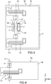
- a structure S3 comprising another example of a hinge according to the first embodiment comprising a single bending element E1.
- this is aligned with an axis of symmetry of the structure, ensuring a balanced structure.
- a hinge comprising a single flexion element which is not aligned with an axis of symmetry of the structure does not depart from the scope of the present invention.
- the hinge also comprises two torsion beams 6 arranged on either side of the bending element E1.
- the structure does not include measuring means, but it will be understood that they can be arranged for example as in the structure S1 or the structure S5.
- a hinge comprising a single bending element and a single torsion beam is not outside the scope of the present invention.
- the measuring means comprise two piezoresistive gauges.
- the detection means comprise piezoelectric gauges.
- the detection means comprise one or more resonant beams. For this, an electrode is placed so as to create an electrostatic force on the gauge in order to put it into resonance. The change in the resonant frequency of the gauge due to the strain is measured by means of a specific circuit which may be a phase locked loop.
- the axis of rotation Y1 passes through the middle of the bending beams.
- a hinge in which the axis of rotation Y1 does not pass through the middle of the bending beams does not go beyond the scope of the present invention, the hinge would then have greater stiffness out of the plane.
- the bending beams are offset with respect to each other in the plane in the X direction, i.e. their centers are not aligned with the Y1 axis.
- the hinge then exhibits increased flexural stiffness.
- the torsion beams are made in the same layer as the torsion elements and are therefore also the seats of internal stresses which will relax when the suspended structure is released. This relaxation can for example cause buckling of the beams.
- the torsion elements T2 comprises at least one pair of torsion beams mechanically connected to each other in series.
- the two torsion elements have similar structures, only one of the torsion elements T2 will be described in detail.
- the torsion element T2 has a pair of torsion beams 28, 30 arranged parallel to each other and symmetrically arranged with respect to the axis of rotation Y1 so that their combined actions effectively define the axis of rotation Y1.
- the two torsion beams are connected to each other directly by their longitudinal ends 28.1, 30.1 and 28.2, 30.2 respectively so as to form a rectangle.
- the connection between the longitudinal ends 28.1, 30.1 and the connection between the longitudinal ends 28.1, 30.2 are rigid with respect to the beams 28, 30.
- the bending beam 28 is connected directly to the support via an anchoring stud 34, by example at its middle
- the bending beam 30 is connected directly to the mobile part, for example at its middle.
- the ends 28.1, 30.1, 28.2, 30.2 of the beams 28, 30 are free to move, allowing the internal stresses to the torsion beams 28, 30 to be released.
- the stresses of 28 and 30 being very close, their ends 28.1, 30.1 and 28.2, 30.2 will move substantially identically and the rigid connection between them does not hinder the release of the stresses.
- the torsion beams 28 and 30 are only connected by one of their ends, for example by the ends 28.2 and 30.2, and the ends 28.1 and 30.1 correspond to the attachment to the anchoring stud 234 and to the moving part respectively.
- the structures described above advantageously comprise at least one lower stop and / or at least one upper stop to limit the amplitude of out-of-plane displacement of the mobile part and to prevent damage to the structure, for example when an external shock. is applied to the structure.
- the stops are of a type well known to those skilled in the art.
- means for moving the mobile part in the out-of-plane direction are provided, for example these are electrostatic means.
- the integration of bending elements, bending beams or bending elements in the moving part can be more or less important depending on the space available and / or the mass required for the moving part, which allows to offer a large number of structure configurations that can be adapted to many applications.
- the position of the movable part relative to the substrate is known and is not modified when the movable part is released.
- the structure can be produced by conventional microelectronic techniques, without adding a complex step, for example the production method described in the document EP2211185 can be implemented.
- the release of the internal stresses of the layer 2300 does not cause the movable part to tilt, but the latter substantially retains its position in the mean plane of the structure.
- the hinges according to the invention are particularly suited to the production of structures for M & NEMS systems used in the production of sensors or actuators.
Description
La présente invention se rapporte à une charnière hors-plan pour structure micro et/ou nanomécanique, notamment pour système microélectromécanique, offrant une sensibilité aux contraintes internes réduite. LesThe present invention relates to an out-of-plane hinge for a micro and / or nanomechanical structure, in particular for a microelectromechanical system, offering reduced sensitivity to internal stresses. The
systèmes microélectromécaniques ou MEMS (microelectromechanical systems en terminologie anglo-saxonne) et les systèmes micro et nanoélectromécaniques ou systèmes M&NEMS (micro & nanoelectromechanical systems en terminologie anglo-saxonne) sont utilisés pour réaliser des capteurs ou des actionneurs. Ils comportent au moins un élément mobile par rapport à un substrat. Par exemple dans le cas d'un capteur, le déplacement de la partie mobile ou masse est mesurée et peut être traduit en une caractéristique à détecter, par exemple une accélération, et dans le cas d'un actionneur, l'élément mobile est déplacé par exemple au moyen de forces électrostatiques, par exemple pour déplacer un micromiroir.microelectromechanical systems or MEMS (microelectromechanical systems in English terminology) and micro and nanoelectromechanical systems or M & NEMS systems (micro & nanoelectromechanical systems in English terminology) are used to make sensors or actuators. They include at least one mobile element relative to a substrate. For example in the case of a sensor, the displacement of the moving part or mass is measured and can be translated into a characteristic to be detected, for example an acceleration, and in the case of an actuator, the moving element is moved for example by means of electrostatic forces, for example to move a micromirror.
L'élément mobile est suspendu par rapport au substrat et suivant les applications on peut souhaiter qu'il ait un déplacement dans le plan du système ou un déplacement hors-plan, i.e. orthogonalement au plan du système.The mobile element is suspended with respect to the substrate and depending on the applications we may wish it to have a displacement in the plane of the system or an out-of-plane displacement, i.e. orthogonally to the plane of the system.
Sur la
La structure s'étendant dans le plan XY, comporte une masse 1000 apte à se déplacer dans une direction hors-plan Z par rapport à un support 1002. La structure comporte une charnière 1004 formant une articulation en rotation 1004 entre le support 1002 et la masse 1000, la charnière présentant un axe de rotation Y1 dans le plan. La charnière relie un bord de la masse au support, et comporte deux poutres 1006 destinées à être sollicitées en torsion et coaxiales à l'axe de rotation et deux poutres 1008 destinées à être sollicitées en flexion et orthogonales à l'axe de rotation. Les poutres 1006 et 1008 relient la masse au support. Cette structure comporte également deux jauges piézorésistives 1010 permettant de mesurer le déplacement de la masse. Les poutres de flexion 1008 ont pour fonction de rigidifier l'articulation dans la direction X. Cependant elles provoquent également une rigidification de l'articulation dans la direction hors-plan, ce qui n'est pas souhaitable. Afin de réduire leur effet sur la rigidité dans la direction Z, l'épaisseur des poutres de flexion est réduite.The structure extending in the XY plane comprises a
Une telle structure est réalisée par les procédés de la microélectronique mettant en œuvre des dépôts, des gravures et une libération de la masse. Par exemple la structure est réalisée par gravure dans une couche formée par épitaxie sur un substrat Silicium sur Isolant ou SOI (Silicon on Insulate) et la masse est libérée en gravant la couche d'oxyde enterrée du substrat SOI.Such a structure is produced by the methods of microelectronics implementing deposits, etchings and a release of the mass. For example, the structure is produced by etching in a layer formed by epitaxy on a Silicon on Insulator or SOI (Silicon on Insulate) substrate and the mass is released by etching the buried oxide layer of the SOI substrate.
Lors de la réalisation de la couche par épitaxie, des contraintes sont générées dans la couche. Ces contraintes peuvent notamment être dues au dopage. Par exemple, les atomes de bore sont plus petits que ceux de silicium et induisent une contrainte en compression dans la maille cristalline du silicium. Cette contrainte peut aussi apparaître avant l'épitaxie, lors du dopage de la couche fine du substrat SOI. Lors de la libération de la structure par gravure, ces contraintes dans toutes les couches sont au moins en partie libérées. Or cette libération des contraintes génère un nouvel équilibre des forces et des moments qui peut conduire à une déformation de la structure. Les poutres de flexion sont formées dans la couche épitaxiée. Lors de la libération de la structure, les contraintes dans les poutres se détendent/ se rétractent. Or les jauges, qui sont parallèles aux poutres de flexion, s'opposent à l'expansion/ la rétraction des poutres de flexion. Les poutres de flexion et les jauges étant dans des plans différents, la masse s'incline. Elle n'est alors plus perpendiculaire à l'axe Z. Lorsque les contraintes internes proviennent de la couche fine du substrat SOI, les jauges 1010 n'étant pas alignées, elles vont induire un couple sur la masse et la faire tourner dans le plan. De plus, les contraintes internes de la couche inférieure des poutres de flexion les font fléchir, provoquant une inclinaison de la masse.During the production of the layer by epitaxy, stresses are generated in the layer. These constraints can in particular be due to doping. For example, boron atoms are smaller than silicon atoms and induce compressive stress in the crystal lattice of silicon. This constraint can also appear before epitaxy, during doping of the thin layer of the SOI substrate. When the structure is released by etching, these stresses in all the layers are at least partially released. However, this release of stresses generates a new balance of forces and moments which can lead to a deformation of the structure. Bending beams are formed in the epitaxial layer. When releasing the structure, the stresses in the beams relax / contract. Now the gauges, which are parallel to the bending beams, oppose the expansion / retraction of the bending beams. The bending beams and the gauges being in different planes, the mass tilts. It is then no longer perpendicular to the Z axis. When the internal stresses come from the thin layer of the SOI substrate, the
Une déformation de la structure peut également survenir lors de la libération de contraintes dans le substrat SOI.Deformation of the structure can also occur during the release of stresses in the SOI substrate.
La contrainte peut aussi résulter de la dilatation thermique. Deux couches n'ayant pas le même coefficient de dilatation se dilatent différemment et entraînent des contraintes à leurs jonctions.Stress can also result from thermal expansion. Two layers that do not have the same coefficient of expansion expand differently and cause stresses at their junctions.
Or cette inclinaison et plus généralement une déformation de la structure ont plusieurs inconvénients. D'une part, elle induit une contrainte dans les jauges, qui peut ne pas être négligeable par rapport à la contrainte à la pleine échelle de mesure, ce qui a pour effet de réduire la plage de variation de la contrainte ou alors peut provoquer un dépassement de la contrainte maximale admissible.However, this inclination and more generally a deformation of the structure have several drawbacks. On the one hand, it induces a stress in the gauges, which may not be negligible compared to the stress at the full measurement scale, which has the effect of reducing the range of variation of the stress or else may cause a exceeding the maximum admissible stress.
D'autre part, une structure microélectromécanique peut comporter des butées haute et basse pour limiter la course hors-plan de la masse, afin d'éviter le dépassement des contraintes admissibles. Lorsque la masse n'est pas inclinée, elle se trouve au repos à égale distance des butées haute et basse. Or en cas d'inclinaison de la masse, les distances entre la masse et les butées haute et basse sont différentes. Si la masse est inclinée vers le support, la distance entre la masse et la butée basse est inférieure à celle entre la masse et la butée haute. Si l'inclinaison de la masse est connue, les butées pourraient être adaptées pour compenser cette différence de distance, or une telle adaptation complexifie le procédé de réalisation. En outre il est difficile de prévoir l'inclinaison de la masse.On the other hand, a microelectromechanical structure can include upper and lower stops to limit the out-of-plane travel of the mass, in order to avoid exceeding the admissible stresses. When the mass is not inclined, it is at rest at an equal distance from the upper and lower stops. However, in the event of inclination of the mass, the distances between the mass and the upper and lower stops are different. If the mass is inclined towards the support, the distance between the mass and the lower stopper is less than that between the mass and the upper stop. If the inclination of the mass is known, the stops could be adapted to compensate for this difference in distance, but such an adaptation complicates the production process. In addition, it is difficult to predict the inclination of the mass.
La déformation de la structure peut également survenir en l'absence de jauges de contrainte.Deformation of the structure can also occur in the absence of strain gauges.
Le document
De manière générale, il est souhaitable que l'effet des contraintes internes sur la structure soit réduit.In general, it is desirable that the effect of internal stresses on the structure be reduced.
C'est par conséquent un but de la présente invention d'offrir une charnière hors-plan pour structure micro et/ou nanomécanique à sensibilité aux contraintes internes réduite.It is consequently an aim of the present invention to offer an out-of-plane hinge for a micro and / or nanomechanical structure with reduced sensitivity to internal stresses.
Le but énoncé ci-dessus est atteint par une charnière hors-plan pour structure micro et/ou nanomécanique qui comporte un support, au moins une partie mobile dans une direction hors-plan ayant les caractéristiques de la revendication 1.The object stated above is achieved by an out-of-plane hinge for a micro and / or nanomechanical structure which comprises a support, at least one part movable in an out-of-plane direction having the characteristics of
L'invention permet de compenser l'effet des contraintes internes libérées le long de la direction dans le plan orthogonale à l'axe de rotation, qui sont les contraintes qui ont l'action la plus gênante sur la structure. Les contraintes internes dans la direction de l'axe de rotation peuvent se libérer et les contraintes dans la direction hors-plan s'additionnent. Mais leurs contributions sur la déformation de la structure sont faibles relativement à celles des contraintes le long de la direction dans le plan orthogonale à l'axe de rotationThe invention makes it possible to compensate for the effect of the internal stresses released along the direction in the plane orthogonal to the axis of rotation, which are the stresses which have the most troublesome action on the structure. Internal stresses in the direction of the axis of rotation can be released, and stresses in the out-of-plane direction add up. But their contributions on the strain of the structure are weak relative to those of the stresses along the direction in the plane orthogonal to the axis of rotation
Ainsi la position repos de la partie mobile par rapport aux butées haute et basse est quasi-centrée, voire centrée.Thus the rest position of the movable part with respect to the top and bottom stops is quasi-centered, or even centered.
Dans le cas d'une structure mettant en œuvre des jauges de contrainte, en position repos de la partie mobile, les jauges sont peu contraintes, voire ne sont pas contraintesIn the case of a structure implementing strain gauges, in the rest position of the mobile part, the gauges are not very strained, or even are not strained.
En d'autres termes, on réalise une articulation pivot comportant au moins un élément de flexion comprenant des poutres de flexion combinées tels qu'une auto-compensation des contraintes internes ait lieu au sein de l'élément de flexion, limitant l'effet des contraintes internes sur la structure.In other words, a pivot joint is produced comprising at least one bending element comprising combined bending beams such that self-compensation of the internal stresses takes place within the bending element, limiting the effect of the bending elements. internal stresses on the structure.
De manière avantageuse, la charnière comporte deux éléments de flexion.Advantageously, the hinge comprises two flexion elements.
Dans un exemple de réalisation, la structure est mise en œuvre dans un système microélectronique et comporte des moyens de détection par exemple comprenant une ou plusieurs jauges de contraintes. Selon une caractéristique avantageuse, les moyens de détection comportent deux jauges disposées l'une par rapport à l'autre de sorte à limiter l'effet, sur la structure, des contraintes internes de la couche dans laquelle elles sont réalisées.In an exemplary embodiment, the structure is implemented in a microelectronic system and comprises detection means, for example comprising one or more strain gauges. According to an advantageous characteristic, the detection means comprise two gauges arranged relative to one another so as to limit the effect, on the structure, of the internal stresses of the layer in which they are made.
Dans un exemple avantageux, la structure comporte des éléments de torsion tels qu'ils limitent également l'effet des contraintes internes des poutres de torsion sur la structure.In an advantageous example, the structure comprises torsion elements such that they also limit the effect of the internal stresses of the torsion beams on the structure.
La présente invention a alors pour objet une charnière pour structure micromécanique et/ou nanomécanique telle que définie par la revendication 1.The subject of the present invention is therefore a hinge for a micromechanical and / or nanomechanical structure as defined by
De préférence, les au moins première et deuxième poutres de flexion ont les mêmes dimensions.Preferably, the at least first and second bending beams have the same dimensions.
Dans un exemple avantageux, la charnière comporte deux éléments de flexion. Par exemple, les éléments de flexion sont disposés de part et d'autre du au moins un élément de torsion.In an advantageous example, the hinge comprises two flexion elements. For example, the bending elements are arranged on either side of the at least one torsion element.
Dans un exemple avantageux, la charnière comporte deux éléments de torsion comportant chacun une poutre de torsion alignée avec l'axe de rotation.In an advantageous example, the hinge comprises two torsion elements each comprising a torsion beam aligned with the axis of rotation.
Selon une caractéristique additionnelle, l'élément de torsion comporte une première poutre de torsion et une deuxième poutre de torsion, et ladite poutre de torsion forme la première poutre de torsion, les premières et deuxièmes poutres de torsion étant parallèles entre elles, et reliées entre elles par au moins une de leurs extrémités longitudinales, l'une des poutres de torsion étant destinée à être reliée mécaniquement directement à la partie mobile et l'autre poutre de torsion étant destinée à être reliée mécaniquement directement au support. Dans un exemple avantageux, la charnière comporte deux paires de poutres de torsion alignées l'une par rapport à l'autre le long de l'axe de rotation.According to an additional characteristic, the torsion element comprises a first torsion beam and a second torsion beam, and said torsion beam forms the first torsion beam, the first and second torsion beams. torsion being parallel to each other, and interconnected by at least one of their longitudinal ends, one of the torsion beams being intended to be mechanically connected directly to the moving part and the other torsion beam being intended to be mechanically connected directly to the support. In an advantageous example, the hinge comprises two pairs of torsion beams aligned with respect to one another along the axis of rotation.
Par exemple, la charnière est réalisée à partir d'un empilement de couches et d'étapes de gravures, dans laquelle au moins les première et deuxième poutres de flexion sont réalisées dans la même couche.For example, the hinge is made from a stack of layers and etching steps, in which at least the first and second bending beams are made in the same layer.
La présente invention a également pour objet une structure micromécanique et/nanomécanique comportant un support, une partie mobile dans la direction hors-plan et une charnière selon l'invention reliant la partie mobile au support.The present invention also relates to a micromechanical and / nanomechanical structure comprising a support, a part movable in the out-of-plane direction and a hinge according to the invention connecting the movable part to the support.
La structure peut comporter des moyens de butée hors-plan pour la masse en éloignement et/ou en rapprochement du support.The structure may include out-of-plane abutment means for the mass moving away from and / or moving towards the support.
La présente invention a également pour objet un système microélectronique comportant au moins une structure selon l'invention.A subject of the present invention is also a microelectronic system comprising at least one structure according to the invention.
Le système microélectronique peut avantageusement comporter des moyens de détection du déplacement hors-plan de la partie mobile, comportant au moins une première jauge de contrainte, la première jauge de contrainte étant reliée mécaniquement directement au support par une première extrémité et à la partie mobile par une deuxième extrémité.The microelectronic system can advantageously comprise means for detecting the out-of-plane displacement of the mobile part, comprising at least a first strain gauge, the first strain gauge being mechanically connected directly to the support by a first end and to the mobile part by a second end.
Par exemple, les moyens de détection du déplacement hors-plan de la partie mobile comportent également une deuxième jauge de contrainte, la deuxième jauge de contrainte étant reliée mécaniquement directement au support par une première extrémité et à la partie mobile par une deuxième extrémité, la première extrémité et la deuxième extrémité de la première jauge de contrainte et la première extrémité et la deuxième extrémité de la deuxième jauge de contrainte étant disposées les unes par rapport aux autres de sorte que l'orientation de la première extrémité vers la deuxième extrémité de la première jauge de contrainte est opposée à l'orientation de la première extrémité vers la deuxième extrémité de la deuxième jauge de contrainte.For example, the means for detecting the out-of-plane displacement of the mobile part also include a second strain gauge, the second strain gauge being mechanically connected directly to the support by a first end and to the mobile part by a second end, the first end and the second end of the first strain gauge and the first end and the second end of the second strain gauge being disposed with respect to each other such that the orientation of the first end towards the second end of the first strain gauge is opposite the orientation of the first end toward the second end of the second strain gauge.
La présente invention sera mieux comprise sur la base de la description qui va suivre et des dessins en annexe sur lesquels:
- La
figure 1 est une vue de dessus et de côté d'une structure MEMS de l'état de la technique. - La
figure 2 est une vue de dessus d'une structure MEMS selon un premier exemple de réalisation. - La
figure 3 est une variante de réalisation de la structure de lafigure 2 . - La
figure 4 est une vue de dessus d'un autre exemple de réalisation de structure comportant un seul élément de flexion. - La
figure 5 est une vue de dessus d'un autre exemple de réalisation de structure comportant des éléments de torsion. - Les
figures 6 A, 6B et 6C sont des représentations schématiques d'étapes d'un exemple de procédé de réalisation d'une structure selon l'invention.
- The
figure 1 is a top and side view of a MEMS structure of the state of the art. - The
figure 2 is a top view of a MEMS structure according to a first exemplary embodiment. - The
figure 3 is an alternative embodiment of the structure of thefigure 2 . - The
figure 4 is a top view of another exemplary embodiment of a structure comprising a single bending element. - The
figure 5 is a top view of another exemplary embodiment of a structure comprising torsion elements. - The
figures 6 A, 6B and 6C are schematic representations of steps of an example of a method for producing a structure according to the invention.
La présente invention concerne les charnières pour les structures micromécaniques et/ou nanomécaniques, notamment mises en œuvre dans des systèmes MEMS et/ou NEMS appliquées par exemple à des accéléromètres, des gyromètres, des capteurs de gaz, des actionneurs...Dans la description qui va suivre la structure sera désignée structure MEMS.The present invention relates to hinges for micromechanical and / or nanomechanical structures, in particular implemented in MEMS and / or NEMS systems applied for example to accelerometers, gyrometers, gas sensors, actuators, etc. which will follow the structure will be called MEMS structure.
Sur la
La structure MEMS S1 comporte une partie mobile M suspendue à un support 2 au moyen d'une charnière 4 formant une articulation pivot 4.The MEMS structure S1 comprises a mobile part M suspended from a
Par exemple, la partie mobile M peut être une masse inertielle dans le cas d'un accéléromètre, ou un micromiroir ou une plateforme orientable dans le cas d'un actionneur.For example, the mobile part M can be an inertial mass in the case of an accelerometer, or a micromirror or an orientable platform in the case of an actuator.
La partie mobile M s'étend dans le plan de la structure défini par les axes X et Y. Le plan de la structure est le plan moyen de la structure qui correspond au plan de la feuille dans la représentation de la
La partie suspendue est destinée à se déplacer dans une direction hors-plan Z, orthogonale aux axes X et Y.The suspended part is intended to move in an out-of-plane Z direction, orthogonal to the X and Y axes.
La charnière a un axe Y1 parallèle à l'axe Y.The hinge has a Y1 axis parallel to the Y axis.
La charnière 4 est reliée à un bord de la partie suspendue M.The
Dans l'exemple représenté, la charnière 4 comporte deux poutres 6 s'étendant le long de l'axe Y1 et destinées à être sollicitées en torsion lors du déplacement de la masse mobile dans la direction hors-plan. Chaque poutre de torsion 6 est reliée par une extrémité longitudinale à un plot d'ancrage P du support, et par une autre extrémité longitudinale à la partie mobile M.In the example shown, the
La charnière comporte également deux éléments E1 s'étendant perpendiculairement à l'axe Y1 entre la partie mobile M et le support 2. Les éléments E1 sont destinés à être sollicités en flexion et seront désignés par la suite « éléments de flexion ».The hinge also comprises two elements E1 extending perpendicularly to the axis Y1 between the movable part M and the
Les deux éléments E1 ont des structures similaires, un seul de ces éléments sera décrit en détail.The two elements E1 have similar structures, only one of these elements will be described in detail.
L'élément de flexion E1 comporte une paire de première et deuxième poutres 12.1, 12.2 parallèles entre elles et perpendiculaires à l'axe Y1. Dans cet exemple, l'axe Y1 passe par le milieu des première et deuxième poutres.The bending element E1 comprises a pair of first and second beams 12.1, 12.2 mutually parallel and perpendicular to the axis Y1. In this example, the Y1 axis passes through the middle of the first and second beams.
Chaque poutre 12.1, 12.2 est reliée par une première extrémité longitudinale 12.11, 12.21 à un plot d'ancrage 14, 16 du support respectivement, et par une deuxième extrémité 12.12, 12.22 à la partie mobile M. Les poutres sont disposées tête-bêche, i.e.la première extrémité 12.11 de la première poutre et la première extrémité 12.21 de la deuxième poutre sont disposées chacune de part et d'autre l'axe de rotation Y1, ainsi que les deuxièmes extrémités 12.12 et 12.22.Each beam 12.1, 12.2 is connected by a first longitudinal end 12.11, 12.21 to an
Les contraintes internes à chaque poutre 12.1, 12.2, qui sont libérées lors de la fabrication, s'exercent entre la première extrémité 12.11, 12.21 reliées au support et l'extrémité 12.12, 12.22 reliée à la partie mobile.The stresses internal to each beam 12.1, 12.2, which are released during manufacture, are exerted between the first end 12.11, 12.21 connected to the support and the end 12.12, 12.22 connected to the mobile part.
La disposition tête-bêche des poutres 12.1, 12.2, et notamment la disposition de leur ancrage au support, ont pour conséquence que les contraintes internes dans la direction X dans la première poutre 12.1 s'exercent sur la masse dans un sens opposé à celui dans lequel s'exercent les contraintes internes dans la direction X dans la deuxième poutre 12.2. Ainsi les contraintes internes dans la direction X à la première poutre 12.1 ont une action sur la partie mobile M opposée à celle exercée par la deuxième poutre 12.2. Or, puisque les poutres ont sensiblement les mêmes caractéristiques, i.e. sensiblement les mêmes dimensions aux marges dues au procédé de réalisation, et sont réalisées dans la même couche, les contraintes internes dans la direction X dans les deux poutres sont proches ou égales et se neutralisent quasi entièrement ou entièrement. L'élément de flexion E1 n'exerce alors pas ou peu d'effort sur la partie mobile, elle n'est donc pas déformée sous l'effet de la relaxation des contraintes internes, ou alors de manière négligeable.The head-to-tail arrangement of the beams 12.1, 12.2, and in particular the arrangement of their anchoring to the support, has the consequence that the internal stresses in the direction X in the first beam 12.1 are exerted on the mass in a direction opposite to that in which exerts the internal stresses in the direction X in the second beam 12.2. Thus the internal stresses in the direction X at the first beam 12.1 have an action on the mobile part M opposite to that exerted by the second beam 12.2. Now, since the beams have substantially the same characteristics, ie substantially the same dimensions at the margins due to the production process, and are produced in the same layer, the internal stresses in the X direction in the two beams are close or equal and neutralize each other. almost entirely or entirely. The bending element E1 then exerts little or no force on the movable part, it is therefore not deformed under the effect of the relaxation of the internal stresses, or else negligibly.
La structure MEMS S1 comporte également des moyens de mesure 10 du déplacement de la partie mobile. Dans cet exemple, les moyens de mesure 10 comportent des jauges 11 suspendues entre la partie mobile et des plots d'ancrage 18 du support et sont disposées dans un plan distinct d'un plan parallèle au plan XY et contenant l'axe de rotation Y1. Les jauges 11 sont disposées de sorte que, lorsqu'une jauge est sollicitée en traction, l'autre est sollicitée en compression.The MEMS structure S1 also comprises means 10 for measuring the displacement of the mobile part. In this example, the measuring means 10 comprise
Les poutres de flexion de chaque élément de flexion sont montées mécaniquement en parallèle.The bending beams of each bending element are mechanically mounted in parallel.
Sur la
En effet il peut exister une contrainte compressive dans la couche servant à la fabrication des jauges, due à l'implantation de dopants, et qui est libérée lors de la libération des jauges. Cette contrainte peut participer à la déformation de la structure.In fact, there may be a compressive stress in the layer used for the manufacture of the gauges, due to the implantation of dopants, and which is released when the gauges are released. This constraint can participate in the deformation of the structure.
Sur la
La jauge 11 a une extrémité longitudinale 11.1 reliée à la partie mobile et une extrémité longitudinale 11.2 reliée à plot d'ancrage 36. La jauge 11' a une extrémité longitudinale 11.1' reliée à la partie mobile et une extrémité longitudinale 11.2' reliée à plot d'ancrage 38. Les extrémités longitudinales 11.1 et 11.1' sont en regard. Le plot d'ancrage 36 est situé dans une fenêtre 40 formée à travers la partie mobile, dont un montant 42 sert de fixation aux extrémités 11.1, 11.1' des jauges.The
Chaque élément de flexion peut comporter un ensemble de plusieurs poutres de flexion, chaque ensemble assurant une auto-compensation des contraintes internes à ses poutres. La mise en œuvre de plusieurs poutres permet d'augmenter la rigidité dans le plan offerte par les éléments en flexion.Each bending element can include a set of several bending beams, each set providing self-compensation for internal stresses to its beams. The implementation of several beams makes it possible to increase the rigidity in the plane offered by the flexural elements.
Par exemple, chaque élément de flexion peut comporter plusieurs paires de poutres de flexion, chaque paire assurant une auto-compensation des contraintes internes à ses poutres. La mise en œuvre de plusieurs poutres permet d'augmenter la rigidité dans le plan offerte par les éléments en flexion.For example, each bending element can include several pairs of bending beams, each pair providing self-compensation for internal stresses to its beams. The implementation of several beams makes it possible to increase the rigidity in the plane offered by the flexural elements.
Selon un autre exemple, un ensemble comporte plus de deux poutres, par exemple trois poutres, deux poutres d'une première largeur compensent les contraintes de l'autre poutre d'une deuxième largeur égale à deux fois la première largeur. On peut également envisager de réaliser des ensembles avec plusieurs poutres de longueurs différentes et assurant une auto-compensation.According to another example, an assembly comprises more than two beams, for example three beams, two beams of a first width compensate for the stresses of the other beam of a second width equal to twice the first width. It is also possible to envisage producing assemblies with several beams of different lengths and ensuring self-compensation.
De plus, dans l'exemple représenté, la partie mobile est structurée de sorte à intégrer les éléments de flexion. La partie comporte des découpes 20 s'étendant parallèlement à l'axe X et logeant les plots d'ancrage et les poutres de flexion et une découpe 22 logeant les plots d'ancrage et les poutres de torsion. Cet arrangement permet d'offrir une structure compacte.In addition, in the example shown, the mobile part is structured so as to integrate the bending elements. The part has
Sur la
La charnière comporte également deux poutres de torsion 6 disposées de part et d'autre de l'élément de flexion E1. Dans cet exemple, la structure ne comporte pas de moyens de mesure, mais il sera compris qu'ils peuvent être agencés par exemple comme dans la structure S1 ou la structure S5.The hinge also comprises two
Une charnière comportant un seul élément de flexion et une seule poutre de torsion ne sort pas du cadre de la présente invention.A hinge comprising a single bending element and a single torsion beam is not outside the scope of the present invention.
Dans les exemples décrits, les moyens de mesure comportent deux jauges piézorésistives. En variante les moyens de détection comportent des jauges piézoélectriques. En variante encore, les moyens de détection comportent une ou des poutres résonantes. Pour cela, une électrode est disposée de sorte à créer une force électrostatique sur la jauge afin de la mettre en résonance. La variation de la fréquence de résonance de la jauge due à la contrainte est mesurée au moyen d'un circuit spécifique qui peut être une boucle à verrouillage de phase.In the examples described, the measuring means comprise two piezoresistive gauges. As a variant, the detection means comprise piezoelectric gauges. As a further variant, the detection means comprise one or more resonant beams. For this, an electrode is placed so as to create an electrostatic force on the gauge in order to put it into resonance. The change in the resonant frequency of the gauge due to the strain is measured by means of a specific circuit which may be a phase locked loop.
Il sera compris que les agencements des éléments de flexion par rapport aux poutres de flexion et/ou par rapport aux moyens de détection peuvent variés.It will be understood that the arrangements of the bending elements relative to the bending beams and / or relative to the detection means may vary.
Dans les exemples décrits et de manière avantageuse, l'axe de rotation Y1 passe par le milieu des poutres de flexion. Néanmoins une charnière dans laquelle l'axe de rotation Y1 ne passerait pas par le milieu des poutres de flexion ne sort pas du cadre de la présente invention, la charnière présenterait alors une plus grande raideur hors-plan.In the examples described and advantageously, the axis of rotation Y1 passes through the middle of the bending beams. However, a hinge in which the axis of rotation Y1 does not pass through the middle of the bending beams does not go beyond the scope of the present invention, the hinge would then have greater stiffness out of the plane.
En variante, les poutres de flexion sont décalées l'une par rapport à l'autre dans le plan dans la direction X, i.e. leurs centres ne sont pas alignés sur l'axe Y1. La charnière présente alors une raideur en flexion augmentée.Alternatively, the bending beams are offset with respect to each other in the plane in the X direction, i.e. their centers are not aligned with the Y1 axis. The hinge then exhibits increased flexural stiffness.
Sur la
En effet, les poutres de torsion sont réalisées dans la même couche que les éléments de torsion et sont donc également les sièges de contraintes internes qui vont se relaxer lors de la libération de la structure suspendue. Cette relaxation peut par exemple provoquer un flambage des poutres.In fact, the torsion beams are made in the same layer as the torsion elements and are therefore also the seats of internal stresses which will relax when the suspended structure is released. This relaxation can for example cause buckling of the beams.
Les éléments de torsion T2 comporte au moins une paire de poutres de torsion reliées mécaniquement entre elles en série.The torsion elements T2 comprises at least one pair of torsion beams mechanically connected to each other in series.
Les deux éléments de torsion ont des structures similaires, seul l'un des éléments de torsion T2 sera décrit en détail.The two torsion elements have similar structures, only one of the torsion elements T2 will be described in detail.
L'élément de torsion T2 comporte une paire de poutres de torsion 28, 30 disposées parallèlement l'une par rapport à l'autre et disposées symétriquement par rapport à l'axe de rotation Y1 de sorte que leurs actions combinées définissent effectivement l'axe de rotation Y1.The torsion element T2 has a pair of
Les deux poutres de torsion sont reliées l'une à l'autre directement par leurs extrémités longitudinales 28.1, 30.1 et 28.2, 30.2 respectivement de sorte à former un rectangle. La liaison entre les extrémités longitudinales 28.1, 30.1 et la liaison entre les extrémités longitudinales 28.1, 30.2 sont rigides par rapport aux poutres 28, 30. Par ailleurs la poutre de flexion 28 est reliée directement au support via un plot d'ancrage 34, par exemple au niveau de son milieu, et la poutre de flexion 30 est reliée directement à la partie mobile, par exemple au niveau de son milieu.The two torsion beams are connected to each other directly by their longitudinal ends 28.1, 30.1 and 28.2, 30.2 respectively so as to form a rectangle. The connection between the longitudinal ends 28.1, 30.1 and the connection between the longitudinal ends 28.1, 30.2 are rigid with respect to the
Les extrémités 28.1, 30.1, 28.2, 30.2 des poutres 28, 30 sont libres de se déplacer, permettant aux contraintes internes aux poutres de torsion 28, 30 de se libérer. Les contraintes de 28 et de 30 étant très proches, leurs extrémités 28.1, 30.1 et 28.2, 30.2 vont se déplacer sensiblement identiquement et la liaison rigide entre elles n'entrave pas la libération des contraintes.The ends 28.1, 30.1, 28.2, 30.2 of the
Les contraintes internes ne s'appliquent alors pas sur la partie mobile. Chaque ensemble de torsion gère ses propres contraintes internes.The internal stresses do not then apply to the mobile part. Each torsion set manages its own internal constraints.
En variante, les poutres de torsion 28 et 30 ne sont reliées que par l'une de leurs extrémités, par exemple par les extrémités 28.2 et 30.2, et les extrémités 28.1 et 30.1 correspondent à la fixation au plot d'ancrage 234 et à la partie mobile respectivement.As a variant, the
Les structures décrites ci-dessus comportent avantageusement au moins une butée inférieure et/ou au moins une butée supérieure pour limiter l'amplitude de déplacement hors-plan de la partie mobile et éviter un endommagement de la structure, par exemple lorsqu'un choc extérieur est appliqué à la structure. Les butées sont de type bien connu par l'homme du métier.The structures described above advantageously comprise at least one lower stop and / or at least one upper stop to limit the amplitude of out-of-plane displacement of the mobile part and to prevent damage to the structure, for example when an external shock. is applied to the structure. The stops are of a type well known to those skilled in the art.
Dans le cas où la structure est utilisée pour réaliser un actionneur, des moyens pour déplacer dans la direction hors-plan la partie mobile sont prévues, par exemple il s'agit de moyens électrostatiques.In the case where the structure is used to produce an actuator, means for moving the mobile part in the out-of-plane direction are provided, for example these are electrostatic means.
En outre l'intégration des éléments de flexion, des poutres de flexion ou éléments de flexion dans la partie mobile peut être plus ou moins importante en fonction de l'espace disponible et/ou de la masse requise pour la partie mobile, ce qui permet d'offrir un grand nombre de configurations de structure pouvant s'adapter à de nombreuses applications.In addition, the integration of bending elements, bending beams or bending elements in the moving part can be more or less important depending on the space available and / or the mass required for the moving part, which allows to offer a large number of structure configurations that can be adapted to many applications.
Grâce à l'invention la position de la partie mobile par rapport au substrat est connue et n'est pas modifiée lors de la libération de la partie mobile.Thanks to the invention, the position of the movable part relative to the substrate is known and is not modified when the movable part is released.
La structure peut être réalisée par les techniques classiques de la microélectronique, sans ajouter d'étape complexe, par exemple le procédé de réalisation décrit dans le document
Un exemple de procédé de réalisation va être décrit ci-dessous.An exemplary production method will be described below.
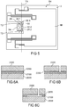
Par exemple, à partir d'un substrat silicium sur isolant ou SOI (Silicon On Insulate), comportant une couche 2000 de silicium, une couche 2100 d'oxyde de silicium et une couche 2200 de silicium monocristallin, le procédé comporte :
- Une étape de formation d'une couche de silicium monocristallin 2300 par exemple par dépôt par épitaxie de silicium sur la couche 2200 (
figure 6A ). - Une étape de structuration des
couches 2200 et 2300 par photolithographie et gravure pour délimiter la partie mobile, la ou les jauges, et la charnière comportant la ou les poutres de flexion et le ou les éléments de flexion (figure 6B ). Par exemple les jauges sont réalisées uniquement dans la couche 2200. Dans ce cas, on réalise préalablement à la formation de la couche 2300, la structuration de la couche 2200 pour former la ou les jauges, par exemple par gravure, et la protection de la ou des jauges par exemple par formation et structuration d'une couche d'oxyde. Les éléments de flexion sont réalisés dans la couche 2200 et une partie de la couche 2300 et les poutres de torsion sont réalisées dans la couche 2200 et dans toute l'épaisseur de la couche 2300. - Une étape de libération de la partie mobile et de la charnière par gravure de la couche 2100 par exemple au moyen d'acide fluorhydrique (
figure 6C ).
- A step of forming a layer of
monocrystalline silicon 2300, for example by deposition by epitaxy of silicon on the layer 2200 (figure 6A ). - A step of structuring
layers figure 6B ). For example, the gauges are produced only in thelayer 2200. In this case, prior to the formation of thelayer 2300, the structuring of thelayer 2200 is carried out to form the gauge or gauges, for example by etching, and the protection of the layer. or some gauges, for example by forming and structuring an oxide layer. Bending elements are made inlayer 2200 and part oflayer 2300 and torsion beams are made inlayer 2200 and throughout the thickness oflayer 2300. - A step of freeing the mobile part and the hinge by etching the
layer 2100, for example by means of hydrofluoric acid (figure 6C ).
Lors du dépôt de la couche 2300, des contraintes en compression peuvent être générées dans celle-ci, notamment en cas de dopage. L'implantation de dopant dans la couche 2200 peut aussi générer des contraintes dans cette couche inférieureDuring the deposition of the
Grâce à l'invention, lors de la libération de la partie mobile le relâchement des contraintes internes à la couche 2300 ne provoque pas d'inclinaison de la partie mobile mais celle-ci conserve sensiblement sa position dans le plan moyen de la structure.Thanks to the invention, when the movable part is released, the release of the internal stresses of the
Les charnières selon l'invention sont particulièrement adaptées à la réalisation de structures pour les systèmes M&NEMS utilisés dans la réalisation de capteurs ou des actionneurs.The hinges according to the invention are particularly suited to the production of structures for M & NEMS systems used in the production of sensors or actuators.
Claims (13)
- Hinge for a micromechanical and/or nanomechanical structure comprising a support (2), at least one movable part (M) in an out-of-plane direction (Z) with respect to the support (2), said hinge being intended to suspend the movable part (m) from the support (2) allowing for the out-of-plane displacement of the movable part (M), the hinge (4) comprising at least one torsion element comprising at least one beam (6) aligned with or parallel to the axis (Y1) of rotation of the hinge, and intended to be deformed in torsion, at least one bending element (E1) intended to be deformed in bending, said bending element (E1) being intended to mechanically connect the movable part (M) and the support (2) and comprising at least one first bending beam (12.1) and at least one second bending beam (12.2) extending perpendicularly to the axis of rotation (Y1) of the hinge (4), the first bending beam (12.1) being intended to be mechanically connected directly to the support (2) by a first end (12.11) and to the movable part (M) by a second end (12.12), and the second bending beam (12.2) being intended to be mechanically connected directly to the support (2) by a first end (12.21) and to the movable part (M) by a second end (12.21), the first end (12.11) and the second end (12.12) of the first bending beam (12.1) and the first end (12.21) and the second end (12.22) of the second bending beam (12.2) being disposed with respect to one another in such a way that the orientation of the first end (12.21) towards the second end (12.22) of the first bending beam (12.1) is opposed to the orientation of the first end (12.21) towards the second end (12.22) of the second bending beam (12.2), characterised in that the first end (12.11) and the second end (12.12) of the first bending beam (12.1) are located on each side of the axis of rotation (Y1) and the first end (12.21) and the second end (12.22) of the second bending beam (12.2) are located on each side of the axis of rotation (Y1).
- Hinge according to claim 1, wherein the at least one first (12.1) and second (12.2) bending beams have the same dimensions.
- Hinge according to claim 1 or 2, comprising two bending elements (E1).
- Hinge according to claim 3, wherein the bending elements (E1) are disposed on either side of the at least one torsion element (6).
- Hinge according to any of claims 1 to 4, comprising two torsion elements each comprising a torsion beam (6) aligned with the axis of rotation.
- Hinge according to any of claims 1 to 5, wherein the torsion element (T2) comprises a first torsion beam (28) and a second torsion beam (30), and said torsion beam forms the first torsion beam, the first and second torsion beams being parallel to one another, and connected together by at least one of the longitudinal ends thereof, one of the torsion beams being intended to be mechanically connected directly to the movable part and the other torsion beam being intended to be mechanically connected directed to the support.
- Hinge according to claim 6, comprising two pairs of torsion beams aligned relative to each other along the axis of rotation.
- Hinge according to any of claims 1 to 7, comprising a stack of layers partly etched, wherein at least the first and second bending beams are made in the same layer.
- Micromechanical and/or nanomechanical structure comprising a support, a movable part in the out-of-plane direction and a hinge according to any of claims 1 to 8 connecting the movable part to the support.
- Structure according to claim 9, comprising at least one out-of-plane abutment for the mass moving away from and/or moving towards the support.
- Microelectronic system comprising at least one structure according to claim 9 or 10.
- Microelectronic system according to claim 11, comprising detection means for detecting the out-of-plane displacement of the movable part, comprising at least one first stress gauge, the first stress gauge being mechanically connected directly to the support (2) by a first end and to the movable part (M) by a second end.
- Microelectronic system according to claim 12, wherein the detection means for detecting the out-of-plane displacement of the movable part also comprises a second stress gauge, the second stress gauge being mechanically connected directly to the support (2) by a first end and to the movable part (M) by a second end, the first end and the second end of the first stress gauge and the first end and the second end of the second stress gauge being disposed with respect to one another in such a way that the orientation of the first end towards the second end of the first stress gauge is opposed to the orientation of the first end (12.21) towards the second end (12.22) of the second stress gauge.
Applications Claiming Priority (1)
| Application Number | Priority Date | Filing Date | Title |
|---|---|---|---|
| FR1903730A FR3094708B1 (en) | 2019-04-08 | 2019-04-08 | OFF-PLANE HINGE FOR MICROMECHANICAL AND/OR NANOMECHANICAL STRUCTURE WITH REDUCED SENSITIVITY TO INTERNAL STRESS |
Publications (2)
| Publication Number | Publication Date |
|---|---|
| EP3722253A1 EP3722253A1 (en) | 2020-10-14 |
| EP3722253B1 true EP3722253B1 (en) | 2021-12-15 |
Family
ID=67810776
Family Applications (1)
| Application Number | Title | Priority Date | Filing Date |
|---|---|---|---|
| EP20168233.3A Active EP3722253B1 (en) | 2019-04-08 | 2020-04-06 | Out-of-plane hinge for micromechanical and/or nanomechanical structure with reduced sensitivity to internal constraints |
Country Status (3)
| Country | Link |
|---|---|
| US (1) | US11384789B2 (en) |
| EP (1) | EP3722253B1 (en) |
| FR (1) | FR3094708B1 (en) |
Families Citing this family (2)
| Publication number | Priority date | Publication date | Assignee | Title |
|---|---|---|---|---|
| FR3098809B1 (en) * | 2019-07-18 | 2021-06-18 | Commissariat Energie Atomique | Mechanical link for MEMS and NEMS mechanical structure, and MEMS and NEMS structure including such a mechanical link |
| TWI803219B (en) * | 2021-03-03 | 2023-05-21 | 美商安托梅拉公司 | Radio frequency (rf) semiconductor devices including a ground plane layer having a superlattice and associated methods |
Family Cites Families (14)
| Publication number | Priority date | Publication date | Assignee | Title |
|---|---|---|---|---|
| EP1119792A2 (en) * | 1998-09-02 | 2001-08-01 | Xros, Inc. | Micromachined members coupled for relative rotation by torsional flexure hinges |
| US6662658B2 (en) * | 2001-01-17 | 2003-12-16 | Honeywell International, Inc. | Whiffletree accelerometer |
| FR2917731B1 (en) * | 2007-06-25 | 2009-10-23 | Commissariat Energie Atomique | DEVICE RESONANT TO PIEZORESISTIVE DETECTION REALIZED IN SURFACE TECHNOLOGIES |
| FR2941533B1 (en) | 2009-01-23 | 2011-03-11 | Commissariat Energie Atomique | SURFACE TECHNOLOGY INERTIAL OR SURFACE SENSOR WITH OFFSETTING DETECTION BY STRAIN GAUGE. |
| FR2951826B1 (en) * | 2009-10-23 | 2012-06-15 | Commissariat Energie Atomique | SENSOR WITH PIEZORESISTIVE DETECTION IN THE PLAN |
| FR2954505B1 (en) * | 2009-12-22 | 2012-08-03 | Commissariat Energie Atomique | MICROMECHANICAL STRUCTURE COMPRISING A MOBILE PART HAVING STOPS FOR OFFLINE SHIFTS OF THE STRUCTURE AND METHOD FOR CARRYING OUT THE SAME |
| FR2957414B1 (en) * | 2010-03-15 | 2012-09-28 | Commissariat Energie Atomique | FORCE SENSOR WITH REDUCED NOISE |
| NL2007554C2 (en) * | 2011-10-10 | 2013-04-11 | Innoluce B V | Mems scanning micromirror. |
| FR2983844B1 (en) * | 2011-12-12 | 2014-08-08 | Commissariat Energie Atomique | PIVOT MECHANICAL BONDING FOR MEMS AND NEMS MECHANICAL STRUCTURES |
| DE102013208824A1 (en) * | 2013-05-14 | 2014-11-20 | Robert Bosch Gmbh | accelerometer |
| FR3030739B1 (en) * | 2014-12-18 | 2019-05-03 | Commissariat A L'energie Atomique Et Aux Energies Alternatives | DYNAMIC PRESSURE SENSOR WITH IMPROVED OPERATION |
| US9625329B2 (en) * | 2015-03-02 | 2017-04-18 | Invensense, Inc. | MEMS sensor offset compensation with strain gauge |
| US10247753B2 (en) * | 2017-02-14 | 2019-04-02 | Nxp Usa, Inc. | MEMS device with off-axis shock protection |
| JP2019132735A (en) * | 2018-01-31 | 2019-08-08 | セイコーエプソン株式会社 | Physical quantity sensor, physical quantity sensor device, electronic device, and mobile vehicle |
-
2019
- 2019-04-08 FR FR1903730A patent/FR3094708B1/en active Active
-
2020
- 2020-04-06 EP EP20168233.3A patent/EP3722253B1/en active Active
- 2020-04-06 US US16/840,540 patent/US11384789B2/en active Active
Also Published As
| Publication number | Publication date |
|---|---|
| US20200318677A1 (en) | 2020-10-08 |
| FR3094708A1 (en) | 2020-10-09 |
| US11384789B2 (en) | 2022-07-12 |
| FR3094708B1 (en) | 2022-12-02 |
| EP3722253A1 (en) | 2020-10-14 |
Similar Documents
| Publication | Publication Date | Title |
|---|---|---|
| EP2791048B1 (en) | Mechanical connection forming a pivot for mems and nems mechanical structures | |
| EP2367015B1 (en) | Force sensor with reduced noise | |
| EP2541222B1 (en) | Pressure-measurement device with optimised sensitivity | |
| EP2008965B1 (en) | Resonant device with piezoresistive detection made using surface technologies | |
| EP2491406B1 (en) | Sensor for in-plane piezoresistive detection | |
| EP2617130B1 (en) | Resonant piezoresistive detector having a resonator connected elastically to the supporting member of the detector, and process for manufacturing said detector | |
| EP3722253B1 (en) | Out-of-plane hinge for micromechanical and/or nanomechanical structure with reduced sensitivity to internal constraints | |
| EP3599469B1 (en) | Accelerometer with detection by strain gauge with improved precision | |
| WO2012085456A2 (en) | Planar structure for a triaxial gyrometer | |
| EP3766830B1 (en) | Mechanical link for mechanical mems and nems structure, and mems and nems structure comprising such a mechanical link | |
| EP3722254A1 (en) | Hinge providing reduced sensitivity to internal constraints | |
| EP3632838B1 (en) | Microelectronic sensor with out-of-plane detection providing a controlled cross sensitivity | |
| EP3498661B1 (en) | Microelectromechanical and/or nanoelectromechanical device providing increased sturdiness | |
| EP0886146B1 (en) | Miniaturised accelerometer of the type utilising force of gravity compensation by means of a spring and method of its manufacture | |
| WO2014096655A1 (en) | Microelectromechanical device possessing at least two deformable elements of different dimensions | |
| EP3415464B1 (en) | Microelectromechanical device having at least one translatably guided mobile element | |
| EP3670438B1 (en) | Out-of-plane joint for micro- and nano-electromechanical systems with reduced non-linearity | |
| FR3126778A1 (en) | FORCE SENSOR WITH AN INCREASED OPERATING RANGE | |
| EP3180287A1 (en) | Microelectromechanical device sensitive to mechanical forces applied off-plane |
Legal Events
| Date | Code | Title | Description |
|---|---|---|---|
| PUAI | Public reference made under article 153(3) epc to a published international application that has entered the european phase |
Free format text: ORIGINAL CODE: 0009012 |
|
| STAA | Information on the status of an ep patent application or granted ep patent |
Free format text: STATUS: REQUEST FOR EXAMINATION WAS MADE |
|
| 17P | Request for examination filed |
Effective date: 20200406 |
|
| AK | Designated contracting states |
Kind code of ref document: A1 Designated state(s): AL AT BE BG CH CY CZ DE DK EE ES FI FR GB GR HR HU IE IS IT LI LT LU LV MC MK MT NL NO PL PT RO RS SE SI SK SM TR |
|
| AX | Request for extension of the european patent |
Extension state: BA ME |
|
| GRAP | Despatch of communication of intention to grant a patent |
Free format text: ORIGINAL CODE: EPIDOSNIGR1 |
|
| STAA | Information on the status of an ep patent application or granted ep patent |
Free format text: STATUS: GRANT OF PATENT IS INTENDED |
|
| INTG | Intention to grant announced |
Effective date: 20210706 |
|
| GRAS | Grant fee paid |
Free format text: ORIGINAL CODE: EPIDOSNIGR3 |
|
| GRAA | (expected) grant |
Free format text: ORIGINAL CODE: 0009210 |
|
| STAA | Information on the status of an ep patent application or granted ep patent |
Free format text: STATUS: THE PATENT HAS BEEN GRANTED |
|
| AK | Designated contracting states |
Kind code of ref document: B1 Designated state(s): AL AT BE BG CH CY CZ DE DK EE ES FI FR GB GR HR HU IE IS IT LI LT LU LV MC MK MT NL NO PL PT RO RS SE SI SK SM TR |
|
| REG | Reference to a national code |
Ref country code: GB Ref legal event code: FG4D Free format text: NOT ENGLISH Ref country code: CH Ref legal event code: EP |
|
| REG | Reference to a national code |
Ref country code: DE Ref legal event code: R096 Ref document number: 602020001268 Country of ref document: DE |
|
| REG | Reference to a national code |
Ref country code: IE Ref legal event code: FG4D Free format text: LANGUAGE OF EP DOCUMENT: FRENCH |
|
| REG | Reference to a national code |
Ref country code: AT Ref legal event code: REF Ref document number: 1455370 Country of ref document: AT Kind code of ref document: T Effective date: 20220115 |
|
| REG | Reference to a national code |
Ref country code: LT Ref legal event code: MG9D |
|
| REG | Reference to a national code |
Ref country code: NL Ref legal event code: MP Effective date: 20211215 |
|
| PG25 | Lapsed in a contracting state [announced via postgrant information from national office to epo] |
Ref country code: RS Free format text: LAPSE BECAUSE OF FAILURE TO SUBMIT A TRANSLATION OF THE DESCRIPTION OR TO PAY THE FEE WITHIN THE PRESCRIBED TIME-LIMIT Effective date: 20211215 Ref country code: LT Free format text: LAPSE BECAUSE OF FAILURE TO SUBMIT A TRANSLATION OF THE DESCRIPTION OR TO PAY THE FEE WITHIN THE PRESCRIBED TIME-LIMIT Effective date: 20211215 Ref country code: FI Free format text: LAPSE BECAUSE OF FAILURE TO SUBMIT A TRANSLATION OF THE DESCRIPTION OR TO PAY THE FEE WITHIN THE PRESCRIBED TIME-LIMIT Effective date: 20211215 Ref country code: BG Free format text: LAPSE BECAUSE OF FAILURE TO SUBMIT A TRANSLATION OF THE DESCRIPTION OR TO PAY THE FEE WITHIN THE PRESCRIBED TIME-LIMIT Effective date: 20220315 |
|
| REG | Reference to a national code |
Ref country code: AT Ref legal event code: MK05 Ref document number: 1455370 Country of ref document: AT Kind code of ref document: T Effective date: 20211215 |
|
| PG25 | Lapsed in a contracting state [announced via postgrant information from national office to epo] |
Ref country code: SE Free format text: LAPSE BECAUSE OF FAILURE TO SUBMIT A TRANSLATION OF THE DESCRIPTION OR TO PAY THE FEE WITHIN THE PRESCRIBED TIME-LIMIT Effective date: 20211215 Ref country code: NO Free format text: LAPSE BECAUSE OF FAILURE TO SUBMIT A TRANSLATION OF THE DESCRIPTION OR TO PAY THE FEE WITHIN THE PRESCRIBED TIME-LIMIT Effective date: 20220315 Ref country code: LV Free format text: LAPSE BECAUSE OF FAILURE TO SUBMIT A TRANSLATION OF THE DESCRIPTION OR TO PAY THE FEE WITHIN THE PRESCRIBED TIME-LIMIT Effective date: 20211215 Ref country code: HR Free format text: LAPSE BECAUSE OF FAILURE TO SUBMIT A TRANSLATION OF THE DESCRIPTION OR TO PAY THE FEE WITHIN THE PRESCRIBED TIME-LIMIT Effective date: 20211215 Ref country code: GR Free format text: LAPSE BECAUSE OF FAILURE TO SUBMIT A TRANSLATION OF THE DESCRIPTION OR TO PAY THE FEE WITHIN THE PRESCRIBED TIME-LIMIT Effective date: 20220316 |
|
| PG25 | Lapsed in a contracting state [announced via postgrant information from national office to epo] |
Ref country code: NL Free format text: LAPSE BECAUSE OF FAILURE TO SUBMIT A TRANSLATION OF THE DESCRIPTION OR TO PAY THE FEE WITHIN THE PRESCRIBED TIME-LIMIT Effective date: 20211215 |
|
| PG25 | Lapsed in a contracting state [announced via postgrant information from national office to epo] |
Ref country code: SM Free format text: LAPSE BECAUSE OF FAILURE TO SUBMIT A TRANSLATION OF THE DESCRIPTION OR TO PAY THE FEE WITHIN THE PRESCRIBED TIME-LIMIT Effective date: 20211215 Ref country code: SK Free format text: LAPSE BECAUSE OF FAILURE TO SUBMIT A TRANSLATION OF THE DESCRIPTION OR TO PAY THE FEE WITHIN THE PRESCRIBED TIME-LIMIT Effective date: 20211215 Ref country code: RO Free format text: LAPSE BECAUSE OF FAILURE TO SUBMIT A TRANSLATION OF THE DESCRIPTION OR TO PAY THE FEE WITHIN THE PRESCRIBED TIME-LIMIT Effective date: 20211215 Ref country code: PT Free format text: LAPSE BECAUSE OF FAILURE TO SUBMIT A TRANSLATION OF THE DESCRIPTION OR TO PAY THE FEE WITHIN THE PRESCRIBED TIME-LIMIT Effective date: 20220418 Ref country code: ES Free format text: LAPSE BECAUSE OF FAILURE TO SUBMIT A TRANSLATION OF THE DESCRIPTION OR TO PAY THE FEE WITHIN THE PRESCRIBED TIME-LIMIT Effective date: 20211215 Ref country code: EE Free format text: LAPSE BECAUSE OF FAILURE TO SUBMIT A TRANSLATION OF THE DESCRIPTION OR TO PAY THE FEE WITHIN THE PRESCRIBED TIME-LIMIT Effective date: 20211215 Ref country code: CZ Free format text: LAPSE BECAUSE OF FAILURE TO SUBMIT A TRANSLATION OF THE DESCRIPTION OR TO PAY THE FEE WITHIN THE PRESCRIBED TIME-LIMIT Effective date: 20211215 |
|
| PG25 | Lapsed in a contracting state [announced via postgrant information from national office to epo] |
Ref country code: PL Free format text: LAPSE BECAUSE OF FAILURE TO SUBMIT A TRANSLATION OF THE DESCRIPTION OR TO PAY THE FEE WITHIN THE PRESCRIBED TIME-LIMIT Effective date: 20211215 Ref country code: AT Free format text: LAPSE BECAUSE OF FAILURE TO SUBMIT A TRANSLATION OF THE DESCRIPTION OR TO PAY THE FEE WITHIN THE PRESCRIBED TIME-LIMIT Effective date: 20211215 |
|
| REG | Reference to a national code |
Ref country code: DE Ref legal event code: R097 Ref document number: 602020001268 Country of ref document: DE |
|
| PG25 | Lapsed in a contracting state [announced via postgrant information from national office to epo] |
Ref country code: IS Free format text: LAPSE BECAUSE OF FAILURE TO SUBMIT A TRANSLATION OF THE DESCRIPTION OR TO PAY THE FEE WITHIN THE PRESCRIBED TIME-LIMIT Effective date: 20220415 |
|
| PLBE | No opposition filed within time limit |
Free format text: ORIGINAL CODE: 0009261 |
|
| STAA | Information on the status of an ep patent application or granted ep patent |
Free format text: STATUS: NO OPPOSITION FILED WITHIN TIME LIMIT |
|
| PG25 | Lapsed in a contracting state [announced via postgrant information from national office to epo] |
Ref country code: DK Free format text: LAPSE BECAUSE OF FAILURE TO SUBMIT A TRANSLATION OF THE DESCRIPTION OR TO PAY THE FEE WITHIN THE PRESCRIBED TIME-LIMIT Effective date: 20211215 Ref country code: AL Free format text: LAPSE BECAUSE OF FAILURE TO SUBMIT A TRANSLATION OF THE DESCRIPTION OR TO PAY THE FEE WITHIN THE PRESCRIBED TIME-LIMIT Effective date: 20211215 |
|
| 26N | No opposition filed |
Effective date: 20220916 |
|
| PG25 | Lapsed in a contracting state [announced via postgrant information from national office to epo] |
Ref country code: SI Free format text: LAPSE BECAUSE OF FAILURE TO SUBMIT A TRANSLATION OF THE DESCRIPTION OR TO PAY THE FEE WITHIN THE PRESCRIBED TIME-LIMIT Effective date: 20211215 |
|
| REG | Reference to a national code |
Ref country code: BE Ref legal event code: MM Effective date: 20220430 |
|
| PG25 | Lapsed in a contracting state [announced via postgrant information from national office to epo] |
Ref country code: MC Free format text: LAPSE BECAUSE OF FAILURE TO SUBMIT A TRANSLATION OF THE DESCRIPTION OR TO PAY THE FEE WITHIN THE PRESCRIBED TIME-LIMIT Effective date: 20211215 Ref country code: LU Free format text: LAPSE BECAUSE OF NON-PAYMENT OF DUE FEES Effective date: 20220406 |
|
| PG25 | Lapsed in a contracting state [announced via postgrant information from national office to epo] |
Ref country code: BE Free format text: LAPSE BECAUSE OF NON-PAYMENT OF DUE FEES Effective date: 20220430 |
|
| PG25 | Lapsed in a contracting state [announced via postgrant information from national office to epo] |
Ref country code: IE Free format text: LAPSE BECAUSE OF NON-PAYMENT OF DUE FEES Effective date: 20220406 |
|
| PG25 | Lapsed in a contracting state [announced via postgrant information from national office to epo] |
Ref country code: IT Free format text: LAPSE BECAUSE OF FAILURE TO SUBMIT A TRANSLATION OF THE DESCRIPTION OR TO PAY THE FEE WITHIN THE PRESCRIBED TIME-LIMIT Effective date: 20211215 |
|
| PGFP | Annual fee paid to national office [announced via postgrant information from national office to epo] |
Ref country code: FR Payment date: 20230424 Year of fee payment: 4 Ref country code: DE Payment date: 20230418 Year of fee payment: 4 |
|
| REG | Reference to a national code |
Ref country code: CH Ref legal event code: PL |
|
| PG25 | Lapsed in a contracting state [announced via postgrant information from national office to epo] |
Ref country code: LI Free format text: LAPSE BECAUSE OF NON-PAYMENT OF DUE FEES Effective date: 20230430 Ref country code: CH Free format text: LAPSE BECAUSE OF NON-PAYMENT OF DUE FEES Effective date: 20230430 |