EP2210976A1 - Wäschebehandlungsmaschine, wie beispielsweise ein Wäschetrockner - Google Patents
Wäschebehandlungsmaschine, wie beispielsweise ein Wäschetrockner Download PDFInfo
- Publication number
- EP2210976A1 EP2210976A1 EP10000336A EP10000336A EP2210976A1 EP 2210976 A1 EP2210976 A1 EP 2210976A1 EP 10000336 A EP10000336 A EP 10000336A EP 10000336 A EP10000336 A EP 10000336A EP 2210976 A1 EP2210976 A1 EP 2210976A1
- Authority
- EP
- European Patent Office
- Prior art keywords
- fragrance
- card
- laundry
- chamber
- carrier
- Prior art date
- Legal status (The legal status is an assumption and is not a legal conclusion. Google has not performed a legal analysis and makes no representation as to the accuracy of the status listed.)
- Granted
Links
- 239000003205 fragrance Substances 0.000 claims abstract description 69
- 238000001035 drying Methods 0.000 claims abstract description 21
- 238000000034 method Methods 0.000 claims description 19
- 230000008569 process Effects 0.000 claims description 19
- 238000001816 cooling Methods 0.000 claims description 4
- 230000001105 regulatory effect Effects 0.000 claims description 3
- 238000003780 insertion Methods 0.000 claims 1
- 230000037431 insertion Effects 0.000 claims 1
- 239000002304 perfume Substances 0.000 description 4
- 238000010438 heat treatment Methods 0.000 description 3
- 239000000126 substance Substances 0.000 description 3
- 239000000203 mixture Substances 0.000 description 2
- 238000009827 uniform distribution Methods 0.000 description 2
- 230000008859 change Effects 0.000 description 1
- 238000012986 modification Methods 0.000 description 1
- 230000004048 modification Effects 0.000 description 1
- 230000032258 transport Effects 0.000 description 1
- 238000002604 ultrasonography Methods 0.000 description 1
Images

Classifications
-
- D—TEXTILES; PAPER
- D06—TREATMENT OF TEXTILES OR THE LIKE; LAUNDERING; FLEXIBLE MATERIALS NOT OTHERWISE PROVIDED FOR
- D06F—LAUNDERING, DRYING, IRONING, PRESSING OR FOLDING TEXTILE ARTICLES
- D06F58/00—Domestic laundry dryers
- D06F58/20—General details of domestic laundry dryers
- D06F58/203—Laundry conditioning arrangements
Definitions
- the invention relates to a laundry treatment machine, such as a tumble dryer, with a drum rotatably mounted in a housing, a closable with a door feed opening, and a fan and a heater for generating a process air stream flowing through a heat exchanger and a lint filter device, and wherein the process air stream a fragrance carrier cooperates, which gives the laundry items a fragrance during the drying period.
- a laundry treatment machine such as a tumble dryer, with a drum rotatably mounted in a housing, a closable with a door feed opening, and a fan and a heater for generating a process air stream flowing through a heat exchanger and a lint filter device, and wherein the process air stream a fragrance carrier cooperates, which gives the laundry items a fragrance during the drying period.
- the fragrance carrier is designed as a container, which is housed for access behind a flap in the housing of the clothes dryer.
- a fragrance carrier is arranged in the region of the lint filter, which can be inserted into a slot provided on the lint filter.
- the fragrance carrier is arranged in the region of the door or the upper flap.
- fragrance is removed from the fragrance carrier over the entire drying process. It is particularly disadvantageous in this case that the fragrance supply also takes place in the heating phases of the drying process. Due to the high temperatures, the perfume evaporates, so that the fragrance carrier due to the hot air does not ensure a uniform distribution of fragrance in the laundry.
- the invention thus raises the problem with a tumble dryer to further develop the scenting process such that an efficient scenting of the laundry items is made possible during the drying process.
- the fragrance carrier is inserted in the form of a compact flash card in a designated switch panel of a tumble dryer.
- the area around the card is thermally insulated so that the card is not heated during the drying process.
- the fragrance from the fragrance carrier is retrieved at any time of the drying process and conveyed into the laundry, wherein the retrieval of the fragrance is preferably carried out in the cooling phases of the drying process.
- a valve opens, wherein the suction in the dryer warm air is transported from the inside of the housing through the card in the process air stream. The warm air dissolves the fragrances from the card and transports them into the laundry.
- the fragrance intensity is adjusted by the duration of the valve opening, wherein the valve opening is preferably at the end of the drying process, when the process air is already cooled and no fragrance is destroyed by excessive temperatures occurs.
- the perfume can be supplied in a cool phase of the program flow.
- the fragrance is not destroyed by too high temperatures, with the result that less fragrance is consumed and a good scent result is achieved.
- the card with the appropriate scent is located in the area of the switch panel. It can not be wrapped by laundry, which has the consequence that a homogeneous scenting of the laundry is given. As a result, a uniform distribution of the fragrance in the drum space is achieved.
- the card is thus not permanently exposed to the hot air flow of the clothes dryer, because only at a desired time the bypass is opened via a valve, so that warm air can dissolve the fragrance from the carrier and take away.
- the card as a fragrance carrier, so has this slider on the sides.
- the fragrance is the fragrance causing substance, which is usually a substance or a mixture or composition of various substances.
- the fragrance carrier embodied as a card is arranged in a bypass duct designed in such a way that the fragrance duration of the fragrance carrier during the drying process is regulated or controlled.
- the fragrance carrier is in this case arranged in a thermally insulated chamber arranged in the air duct. It is the Chamber equipped with an inlet and / or an exhaust valve.
- electrical drives are provided which make particular closing and opening of the individual valve. The control can thus be done via the program control.
- process air flows through the chamber to deliver the fragrance provided on the fragrance carrier.
- valves for the passage of the process air takes place primarily in the cooling phase of the drying process in order not to destroy or change the fragrance or the fragrance in this way.
- the fragrance carrier in this case comprises a card, similar to a check card, which is by a / in the air duct or in the chamber provided slot or drawer, which / corresponds to a provided in the housing wall opening, is inserted.
- the card is provided with slider elements which automatically open the fragrance carrier area on the card when inserted into the chamber and automatically close the fragrance carrier area on the card when the card is removed from the chamber.
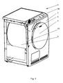
- FIGS. 1 and 2 show a clothes dryer 1 with a rotatably mounted in a housing 2 drum 3.
- the clothes dryer 1 in this case has a door 4, which forms the closable loading opening 5 for the drum 3.
- the tumble dryer 1 has a fan 6 and a heating device 7, wherein fan 6 and heating device 7 are provided for generating a process air stream 8.
- the heated process air 8 flows via a heat exchanger 9 and via a lint filter device 10, with the process air stream 8 a fragrance carrier 11 cooperating, which gives the laundry items 12 a scent.
- the fragrance carrier 11 arranged in a trained as a bypass 13 air duct so that the fragrance duration of the fragrance carrier 11 during the drying process is regulated or controlled.
- the fragrance carrier 11 is arranged in a thermally insulated chamber 14 arranged in the bypass 13.
- This chamber 14 is located behind the housing wall in the upper region of the tumble dryer 1.
- the chamber 14 is equipped with an inlet valve 15 and an outlet valve 16. Both valves 15 and 16 are electrically actuated.
- process air 8 as indicated by the arrow 17 flows through the chamber 14 to deliver the fragrance provided on the fragrance carrier 11.
- the delivery of the perfume provided so that the incoming process air is added via the bypass 13 in front of the heat exchanger 9, in which case the process air 8 flows through the drum 3 with the acted upon fragrance.
- the delivery of the fragrance takes place directly in the drum 3, in which case the bypass 13 opens into the drum 3.
- the control of the valves 15, 16 takes place for the passage of the process air 8 mainly in the cooling phase of the drying process, in which case this is done in particular via the program control of the tumble dryer 1.
- the fragrance carrier 11 in this case comprises a card 18, as in the FIG. 1 indicated in perspective.
- the card 18 is thereby inserted through a slot 14 provided in the chamber which corresponds to an opening provided in the housing wall.
- a slot 14 provided in the chamber which corresponds to an opening provided in the housing wall.
- the card 18 is provided with slide elements that automatically open the Volvic Silver on the card 18 when inserted into the chamber 14 and when pulling out the card 18 from the chamber 14 close the fragrance carrier area on the map 18 again independently.
Landscapes
- Engineering & Computer Science (AREA)
- Textile Engineering (AREA)
- Detail Structures Of Washing Machines And Dryers (AREA)
- Detergent Compositions (AREA)
Abstract
Description
- Die Erfindung betrifft eine Wäschebehandlungsmaschine, wie beispielsweise einen Wäschetrockner, mit einer in einem Gehäuse drehbar gelagerten Trommel, einer mit einer Tür verschließbaren Beschickungsöffnung, sowie einem Gebläse und einer Heizeinrichtung zur Erzeugung eines Prozessluftstromes, der über einen Wärmetauscher sowie eine Flusenfiltereinrichtung strömt, und wobei mit dem Prozessluftstrom ein Duftmittelträger zusammenwirkt, der während der Trocknungsdauer den Wäschestücken eine Duftnote verleiht.
- Bei den Wäschetrocknern des Standes der Technik ist es bekannt, während des Trocknungsvorganges die Wäsche mit einem Duft zu beaufschlagen. So ist aus der
DE 74 39 405 U ein Wäschetrockner mit einer Vorrichtung zur Zugabe eines Duftstoffes bekannt, wobei der Duftmittelaufnahmebehälter über eine Zuführleitung verfügt, die in Verbindung mit dem Trommelraum des Wäschetrockners steht. Dabei ist der Duftmittelträger als Behältnis ausgebildet, wobei dieser für den Zugang hinter einer Klappe im Gehäuse des Wäschetrockners untergebracht ist. Eine andere Art den Duftstoff während des Trocknungsprozesses der Wäsche zuzuführen, ist hier aus der koreanischen PatentschriftKR 10-2007-0007548 A JP 09038388 - Aus der
GB 2 231 944 A - Bei diesen aus dem Stand der Technik bekannten Arten der Beduftung von Wäschestücken während des Trocknungsvorganges wird es als nachteilig angesehen, dass der Duft über den gesamten Trocknungsvorgang dem Duftmittelträger entzogen wird. Besonders nachteilig ist es hierbei, dass die Duftzufuhr auch in den Aufheizphasen des Trocknungsprozesses erfolgt. Infolge der hohen Temperaturen verflüchtigt sich der Duftstoff, so dass der Duftmittelträger infolge der heißen Luft eine gleichmäßige Duftverteilung in der Wäsche nicht sicherstellt.
- Der Erfindung stellt sich somit das Problem bei einem Wäschetrockner den Beduftungsprozess derart weiterzubilden, dass während des Trocknungsprozesses eine effiziente Beduftung der Wäschestücke ermöglicht wird.
- Erfindungsgemäß wird diese Aufgabe durch den Hauptanspruch gelöst; vorteilhafte Ausgestaltungen und Weiterbildungen der Erfindung ergeben sich aus den nachfolgenden Unteransprüchen.
- Die mit der Erfindung erreichten Vorteile bestehen nun darin, dass der Duftträger in Form ähnlich einer Compact-Flash-Karte in eine vorgesehene Schalterblende eines Wäschetrockners gesteckt wird. Der Bereich um die Karte ist hierbei thermisch isoliert, so dass die Karte während des Trocknungsprozesses nicht erwärmt wird. Der Duftstoff aus dem Duftträger wird zu beliebiger Zeit des Trocknungsprozesses abgerufen und in die Wäsche gefördert, wobei die Abrufung des Duftes vorzugsweise in den Abkühlphasen des Trocknungsprozesses vorgenommen wird. Dazu öffnet ein Ventil, wobei durch den Sog im Trockner warme Luft von der Gehäuseinnenseite durch die Karte in den Prozessluftstrom befördert wird. Die warme Luft löst die Duftstoffe aus der Karte und befördert sie in die Wäsche. Die Duftintensität wird durch die Dauer der Ventilöffnung eingestellt, wobei die Ventilöffnung vorzugsweise zum Ende des Trocknungsprozesses, wenn die Prozessluft bereits abgekühlt ist und kein Duftstoff durch zu hohe Temperaturen zerstört wird, erfolgt.
- Vorteilhaft ist dabei, dass der Duftstoff in einer kühlen Phase des Programmablaufs zugeführt werden kann. Dadurch wird der Duftstoff durch zu hohe Temperaturen nicht mehr zerstört, was zur Folge hat, dass auch weniger Duftstoff verbraucht wird und ein gutes Duftergebnis erzielt wird. Die Karte mit der entsprechenden Duftnote befindet sich im Bereich der Schalterblende. Sie kann nicht von Wäschestücken umschlungen werden, was zur Folge hat, dass eine homogene Beduftung der Wäschestücke gegeben ist. Dadurch wird eine gleichmäßige Verteilung des Duftstoffes im Trommelraum erzielt. Die Karte wird somit nicht dauerhaft dem heißen Luftstrom des Wäschetrockners ausgesetzt, weil nur zu einer gewünschten Zeit der Bypass über ein Ventil geöffnet wird, so dass warme Luft den Duftstoff aus dem Träger lösen und mitnehmen kann. Was die Karte als Duftmittelträger betrifft, so besitzt diese Schieber an den Seiten. Diese Schieber haben die Funktion die Karte geschlossen zu halten, wenn sie sich nicht im Trockner befindet. Steckt man die Karte in den Trockner, öffnen sich die Schieber, so dass der Duftstoff entweichen kann. Nimmt man die Karte wieder heraus, schließen sich die Schieber wieder. Somit ist dann die Karte vor selbst entweichenden Duftstoffen geschützt. Als Duftstoff wird die den Duft verursachende Substanz bezeichnet, wobei es sich in der Regel um eine Substanz oder eine Mischung bzw. Zusammensetzung von verschiedenen Substanzen handelt.
- Gemäß der Erfindung wird der als Karte ausgebildete Duftmittelträger in einem als Bypass ausgebildeten Luftkanal derart angeordnet, dass die Beduftungsdauer des Duftmittelträgers während des Trocknungsprozesses regel- bzw. steuerbar ist. Der Duftmittelträger ist hierbei in einer im Luftkanal angeordneten thermisch isolierten Kammer angeordnet. Dabei ist die Kammer mit einem Einlass und/oder einem Auslassventil bestückt. Zur Regelung der Ventile sind elektrische Antriebe vorgesehen, die insbesondere Schließen und Öffnen des einzelnen Ventils vornehmen. Die Ansteuerung kann damit über die Programmsteuerung erfolgen. Sind die Ventile geöffnet, so strömt Prozessluft durch die Kammer zur Abgabe des auf dem Duftmittelträger vorgesehenen Duftstoffes.
- Wie bereits schon erwähnt, erfolgt eine Ansteuerung der Ventile zur Durchleitung der Prozessluft vornehmlich in der Abkühlphase des Trocknungsprozesses, um auf diese Weise den Duftstoff bzw. die Duftnote nicht zu zerstören oder zu verändern.
- Der Duftmittelträger umfasst hierbei eine Karte, ähnlich wie eine Scheckkarte, wobei diese durch einen/einer im Luftkanal oder in der Kammer vorgesehenen Schlitz oder Schublade, der/die mit einer in der Gehäusewand vorgesehenen Öffnung korrespondiert, einschiebbar ist. Die Karte ist mit Schieberelementen versehen, die beim Einführen in die Kammer selbsttätig den Duftträgerbereich auf der Karte öffnen und beim Herausziehen der Karte aus der Kammer den Duftträgerbereich auf der Karte wieder selbsttätig schließen. Somit wird ein effizienter Umgang mit dem Duftstoff auf der Duftmittelträgerkarte erreicht.
- Ein Ausführungsbeispiel der Erfindung ist anhand der nachstehenden
Figuren 1 bis 3 näher erläutert; dabei zeigen: - Figur 1
- eine perspektivische Darstellung eines Wäschetrockners;
- Figur 2
- eine geschnittene Ansicht des Wäschetrockners gemäß der
Fig. 1 ; und - Figur 3
- eine weitere geschnittene Darstellung des Wäschetrockners gemäß der
Fig. 1 in einer weiteren Ausführungsform der Duftmittelzufuhr. - Die
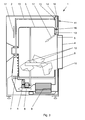
Figuren 1 und2 zeigen einen Wäschetrockner 1 mit einer in einem Gehäuse 2 drehbar gelagerten Trommel 3. Der Wäschetrockner 1 weist hierbei eine Tür 4 auf, die die verschließbare Beschickungsöffnung 5 für die Trommel 3 bildet. In der geschnittenen Ansicht derFigur 2 ist zu erkennen, dass der Wäschetrockner 1 über ein Gebläse 6 und eine Heizeinrichtung 7 verfügt, wobei Gebläse 6 und Heizeinrichtung 7 zur Erzeugung eines Prozessluftstromes 8 vorgesehen sind. Die erwärmte Prozessluft 8 strömt über einen Wärmetauscher 9 sowie über eine Flusenfiltereinrichtung 10, wobei mit dem Prozessluftstrom 8 ein Duftmittelträger 11 zusammenwirkt, der den Wäschestücken 12 eine Duftnote verleiht. Dabei ist, wie insbesondere in derFigur 1 aber auch in derFigur 2 und3 zu erkennen ist, der Duftmittelträger 11 in einem als Bypass 13 ausgebildeten Luftkanal derart angeordnet, dass die Beduftungsdauer des Duftmittelträgers 11 während des Trocknungsprozesses regel- bzw. steuerbar ist. - In den
Figuren 2 und3 ist deutlich zu erkennen, dass der Duftmittelträger 11 in einer im Bypass 13 angeordneten, thermisch isolierten Kammer 14 angeordnet ist. Diese Kammer 14 befindet sich hinter der Gehäusewand im oberen Bereich des Wäschetrockners 1. Wie aus der Figur zu erkennen ist, ist dabei die Kammer 14 mit einem Einlassventil 15 und einem Auslassventil 16 bestückt. Beide Ventile 15 und 16 sind dabei elektrisch ansteuerbar. Sind also die beiden Ventile 15 und 16 geöffnet, so strömt, gemäß Pfeilrichtung 17, Prozessluft 8 durch die Kammer 14 zur Abgabe des auf dem Duftmittelträger 11 vorgesehenen Duftstoffes. Dabei ist insbesondere nach der Version derFigur 2 die Abgabe des Duftstoffes so vorgesehen, dass die einströmende Prozessluft über den Bypass 13 vor dem Wärmetauscher 9 zugegeben wird, wobei dann die Prozessluft 8 durch die Trommel 3 mit der beaufschlagten Duftnote strömt. - Bei der
Figur 3 erfolgt die Abgabe des Duftstoffes unmittelbar in die Trommel 3, wobei hier der Bypass 13 in der Trommel 3 mündet. Die Ansteuerung der Ventile 15, 16 erfolgt zur Durchleitung der Prozessluft 8 vornehmlich in der Abkühlphase des Trocknungsprozesses, wobei hier insbesondere dies über die Programmsteuerung des Wäschetrockners 1 vorgenommen wird. - Der Duftmittelträger 11 umfasst hierbei eine Karte 18, wie diese in der
Figur 1 in der Perspektive angedeutet ist. Die Karte 18 wird dabei durch einen in der Kammer 14 vorgesehenen Schlitz, der mit einer in der Gehäusewand vorgesehenen Öffnung korrespondiert, eingeschoben. Somit ergibt sich auch die Möglichkeit hier entsprechend unterschiedliche Duftnoten auf entsprechenden Karten 18 vorzuhalten, so dass entsprechend des Wunsches hier unterschiedliche Karten 18 vorgehalten werden, die für die Beduftung unterschiedlicher Wäschestücke herangezogen werden können. Nicht näher dargestellt ist hierbei, dass die Karte 18 mit Schieberelementen versehen ist, die beim Einführen in die Kammer 14 selbsttätig den Duftträgerbereich auf der Karte 18 öffnen und beim Herausziehen der Karte 18 aus der Kammer 14 den Duftträgerbereich auf der Karte 18 wieder selbstständig schließen.
Claims (8)
- Wäschebehandlungsmaschine, wie beispielsweise einen Wäschetrockner (1) mit einer in einem Gehäuse (2) drehbar gelagerten Trommel (3), einer mit einer Tür (4) verschließbaren Beschickungsöffnung (5), sowie einem Gebläse (6) und einer Heizeinrichtung (7) zur Erzeugung eines Prozessluftstromes, der über einen Wärmetauscher (9) sowie eine Flusenfiltereinrichtung (10) strömt, und wobei mit dem Prozessluftstrom (8) ein Duftmittelträger (11) zusammenwirkt, der während der Trocknungsdauer den Wäschestücken (12) eine Duftnote verleiht,
dadurch gekennzeichnet,
dass der Duftmittelträger (11) in einem als Bypass (13) ausgebildeten Luftkanal derart angeordnet ist, dass die Beduftungsdauer des Duftmittelträgers (11) während des Trocknungsprozesses regelbar bzw. steuerbar ist, wobei der Duftmittelträger (11) in einer im Bypass (13) angeordneten, thermisch isolierten Kammer (14) angeordnet ist, derart, dass der Duftstoff aus dem Duftmittelträger zu beliebiger Zeit des Trocknungsprozesses abgerufen und in die Wäsche gefördert werden kann. - Wäschebehandlungsmaschine nach Anspruch 1,
dadurch gekennzeichnet,
dass die Kammer (14) mit einem Einlassventil (15) und/oder einem Auslassventil (16) bestückt ist. - Wäschebehandlungsmaschine nach Anspruch 2,
dadurch gekennzeichnet,
dass die Ventile (15, 16) elektrisch ansteuerbar sind. - Wäschebehandlungsmaschine nach Anspruch 3,
dadurch gekennzeichnet,
dass bei geöffneter Ventilstellung Prozessluft (8) durch die Kammer (14) strömt zur Abgabe des auf dem Duftmittelträgers (11) vorgesehenen Duftstoffes. - Wäschebehandlungsmaschine nach Anspruch 4,
dadurch gekennzeichnet,
dass eine Ansteuerung der Ventile (15, 16) zur Durchleitung der Prozessluft (8) vornehmlich in der Abkühlphase des Trocknungsprozesses erfolgt. - Wäschebehandlungsmaschine nach Anspruch 1,
dadurch gekennzeichnet,
dass der Duftmittelträger (11) eine Karte (18) umfasst. - Wäschebehandlungsmaschine nach Anspruch 6,
dadurch gekennzeichnet,
dass die Karte (18) durch einen/eine im Luftkanal oder in der Kammer (14) vorgesehenen Schlitz oder Schublade, der/die mit einer in der Gehäusewand vorgesehenen Öffnung korrespondiert, einschiebbar/einsetzbar ist. - Wäschebehandlungsmaschine nach Anspruch 7,
dadurch gekennzeichnet,
dass die Karte (18) mit Schieberelementen versehen ist, die beim Einführen in die Kammer (14) selbsttätig den Duftträgerbereich auf der Karte (18) öffnen, und beim Herausziehen der Karte (18) aus der Kammer (14) den Duftträgerbereich auf der Karte (18) wieder selbsttätig schließen.
Priority Applications (1)
| Application Number | Priority Date | Filing Date | Title |
|---|---|---|---|
| PL10000336T PL2210976T3 (pl) | 2009-01-27 | 2010-01-15 | Maszyna do traktowania prania, taka jak na przykład suszarka do prania |
Applications Claiming Priority (1)
| Application Number | Priority Date | Filing Date | Title |
|---|---|---|---|
| DE102009006234A DE102009006234B4 (de) | 2009-01-27 | 2009-01-27 | Wäschebehandlungsmaschine, wie beispielsweise ein Wäschetrockner |
Publications (2)
| Publication Number | Publication Date |
|---|---|
| EP2210976A1 true EP2210976A1 (de) | 2010-07-28 |
| EP2210976B1 EP2210976B1 (de) | 2012-01-04 |
Family
ID=42123150
Family Applications (1)
| Application Number | Title | Priority Date | Filing Date |
|---|---|---|---|
| EP10000336A Not-in-force EP2210976B1 (de) | 2009-01-27 | 2010-01-15 | Wäschebehandlungsmaschine, wie beispielsweise ein Wäschetrockner |
Country Status (5)
| Country | Link |
|---|---|
| EP (1) | EP2210976B1 (de) |
| AT (1) | ATE540155T1 (de) |
| DE (1) | DE102009006234B4 (de) |
| ES (1) | ES2375263T3 (de) |
| PL (1) | PL2210976T3 (de) |
Cited By (4)
| Publication number | Priority date | Publication date | Assignee | Title |
|---|---|---|---|---|
| EP2610397A1 (de) * | 2011-12-28 | 2013-07-03 | Electrolux Home Products Corporation N.V. | Wäschetrockner-Haushaltsgerät mit Flüssigkeitsbehälter mit Fülleinlass |
| EP4261340A1 (de) * | 2022-04-11 | 2023-10-18 | BSH Hausgeräte GmbH | Vorrichtung zur handhabung von kleidung |
| EP4261341A1 (de) * | 2022-04-11 | 2023-10-18 | BSH Hausgeräte GmbH | Wäschebehandlungsvorrichtung |
| US20230357978A1 (en) * | 2022-05-05 | 2023-11-09 | Haier Us Appliance Solutions, Inc. | Infuser and receptacle for a laundry appliance |
Families Citing this family (2)
| Publication number | Priority date | Publication date | Assignee | Title |
|---|---|---|---|---|
| DE102011002752B4 (de) * | 2011-01-17 | 2012-08-02 | Henkel Ag & Co. Kgaa | Verfahren zum Betreiben einer Dosiervorrichtung und Dosiervorrichtung |
| US11680352B2 (en) | 2021-10-14 | 2023-06-20 | Haier Us Appliance Solutions, Inc. | Washing machine appliance and additive assembly |
Citations (5)
| Publication number | Priority date | Publication date | Assignee | Title |
|---|---|---|---|---|
| DE7439405U (de) | 1974-11-27 | 1976-06-10 | Miele & Cie, 4830 Guetersloh | Wäschetrockner mit Duftstoffzugabevorrichtung |
| GB2231944A (en) | 1989-05-26 | 1990-11-28 | Sanyo Electric Co | Dispenser on dryer door |
| JPH0938388A (ja) | 1995-08-03 | 1997-02-10 | Matsushita Electric Ind Co Ltd | 衣類乾燥機 |
| US20050050762A1 (en) * | 2003-08-18 | 2005-03-10 | Hood Lisa J. | Volatilizable media holder for a laundry dryer |
| KR20070007548A (ko) | 2005-07-11 | 2007-01-16 | 엘지전자 주식회사 | 건조기의 필터 구조 |
Family Cites Families (3)
| Publication number | Priority date | Publication date | Assignee | Title |
|---|---|---|---|---|
| DE19935984A1 (de) * | 1999-07-30 | 2001-02-01 | Bsh Bosch Siemens Hausgeraete | Vorrichtung und Verfahren zum Desodorieren und Desinfizieren von Wäsche |
| US20020088502A1 (en) * | 2000-10-04 | 2002-07-11 | Van Rompuy Tanya Cecile Corneel | Smart dosing device |
| KR101287963B1 (ko) * | 2006-09-25 | 2013-07-18 | 엘지전자 주식회사 | 향기공급장치 및 이를 구비한 의류처리장치 |
-
2009
- 2009-01-27 DE DE102009006234A patent/DE102009006234B4/de not_active Expired - Fee Related
-
2010
- 2010-01-15 EP EP10000336A patent/EP2210976B1/de not_active Not-in-force
- 2010-01-15 ES ES10000336T patent/ES2375263T3/es active Active
- 2010-01-15 PL PL10000336T patent/PL2210976T3/pl unknown
- 2010-01-15 AT AT10000336T patent/ATE540155T1/de active
Patent Citations (5)
| Publication number | Priority date | Publication date | Assignee | Title |
|---|---|---|---|---|
| DE7439405U (de) | 1974-11-27 | 1976-06-10 | Miele & Cie, 4830 Guetersloh | Wäschetrockner mit Duftstoffzugabevorrichtung |
| GB2231944A (en) | 1989-05-26 | 1990-11-28 | Sanyo Electric Co | Dispenser on dryer door |
| JPH0938388A (ja) | 1995-08-03 | 1997-02-10 | Matsushita Electric Ind Co Ltd | 衣類乾燥機 |
| US20050050762A1 (en) * | 2003-08-18 | 2005-03-10 | Hood Lisa J. | Volatilizable media holder for a laundry dryer |
| KR20070007548A (ko) | 2005-07-11 | 2007-01-16 | 엘지전자 주식회사 | 건조기의 필터 구조 |
Cited By (5)
| Publication number | Priority date | Publication date | Assignee | Title |
|---|---|---|---|---|
| EP2610397A1 (de) * | 2011-12-28 | 2013-07-03 | Electrolux Home Products Corporation N.V. | Wäschetrockner-Haushaltsgerät mit Flüssigkeitsbehälter mit Fülleinlass |
| EP4261340A1 (de) * | 2022-04-11 | 2023-10-18 | BSH Hausgeräte GmbH | Vorrichtung zur handhabung von kleidung |
| EP4261341A1 (de) * | 2022-04-11 | 2023-10-18 | BSH Hausgeräte GmbH | Wäschebehandlungsvorrichtung |
| US20230357978A1 (en) * | 2022-05-05 | 2023-11-09 | Haier Us Appliance Solutions, Inc. | Infuser and receptacle for a laundry appliance |
| US11946189B2 (en) * | 2022-05-05 | 2024-04-02 | Haier Us Appliance Solutions, Inc. | Infuser and receptacle for a laundry appliance |
Also Published As
| Publication number | Publication date |
|---|---|
| EP2210976B1 (de) | 2012-01-04 |
| DE102009006234A1 (de) | 2010-08-12 |
| ES2375263T3 (es) | 2012-02-28 |
| DE102009006234B4 (de) | 2011-06-30 |
| PL2210976T3 (pl) | 2012-05-31 |
| ATE540155T1 (de) | 2012-01-15 |
Similar Documents
| Publication | Publication Date | Title |
|---|---|---|
| EP2210975B1 (de) | Verfahren zur Abgabe eines Duftstoffes während des Trocknungsprozesses in einem Wäschetrockner | |
| EP2210976B1 (de) | Wäschebehandlungsmaschine, wie beispielsweise ein Wäschetrockner | |
| EP2431516B1 (de) | Beduftungseinrichtung für eine Wäschebehandlungsmaschine | |
| DE60219112T2 (de) | Verfahren und Vorrichtung zur Trocknung mittels Luftzirkulation | |
| EP3500800A1 (de) | Haushaltsgargerät | |
| EP2669423A1 (de) | Trocknungseinrichtung zum Trocknen von Wäsche mit einem Behälter zur Aufnahme und Abgabe eines Duftstoffes | |
| EP3138951B1 (de) | Anordnung und verfahren zum einleiten von prozessluft in eine wäschetrommel eines wäschetrockners | |
| EP0669510A1 (de) | Trockner | |
| DE102007016078A1 (de) | Hybridtrockner und Verfahren zum Betreiben eines solchen Hybridtrockners | |
| EP2470713A2 (de) | Verfahren zum betreiben eines adsorptions-trockners und trockner zur realisierung des verfahrens | |
| EP2589699A1 (de) | Wäschebehandlungsschrank | |
| DE102018120954B4 (de) | Programmgesteuerter Wäschetrockner | |
| DE4424846A1 (de) | Trockner | |
| BE1031551B1 (de) | Wäschebehandlungsschrank mit einer Vorrichtung zur Konditionierung der Innenraumluft | |
| DE10233015A1 (de) | Vorrichtung und Verfahren zur Trocknung eines Gasstromes | |
| BE1029736B1 (de) | Wärmepumpentrockner mit Dampferzeuger | |
| DE102023110646A1 (de) | Wäschebehandlungsschrank mit einer Vorrichtung zum Behandeln der Prozessluft | |
| CH222858A (de) | Trocknungseinrichtung. | |
| DE4135909A1 (de) | Verfahren und vorrichtung zum mangeln textilen gutes, insbesondere von waesche | |
| BE1031553A1 (de) | Wäschebehandlungsschrank mit einer Vorrichtung zum Behandeln der Prozessluft | |
| DE2711222A1 (de) | Trocknungseinrichtung fuer tiere | |
| DE3742982C2 (de) | ||
| DE589773C (de) | Vorrichtung zum Chemischreinigen von Textilgut | |
| DE498778C (de) | Verfahren und Vorrichtung zum Trocknen und zur Veredelung von Roh-Kakaobohnen | |
| DE102015107500A1 (de) | Verfahren zum Waschen und/oder Trocknen von Wäsche in einem Waschtrockner |
Legal Events
| Date | Code | Title | Description |
|---|---|---|---|
| PUAI | Public reference made under article 153(3) epc to a published international application that has entered the european phase |
Free format text: ORIGINAL CODE: 0009012 |
|
| AK | Designated contracting states |
Kind code of ref document: A1 Designated state(s): AT BE BG CH CY CZ DE DK EE ES FI FR GB GR HR HU IE IS IT LI LT LU LV MC MK MT NL NO PL PT RO SE SI SK SM TR |
|
| AX | Request for extension of the european patent |
Extension state: AL BA RS |
|
| 17P | Request for examination filed |
Effective date: 20101113 |
|
| RIC1 | Information provided on ipc code assigned before grant |
Ipc: D06F 58/20 20060101AFI20110407BHEP |
|
| GRAP | Despatch of communication of intention to grant a patent |
Free format text: ORIGINAL CODE: EPIDOSNIGR1 |
|
| GRAS | Grant fee paid |
Free format text: ORIGINAL CODE: EPIDOSNIGR3 |
|
| GRAA | (expected) grant |
Free format text: ORIGINAL CODE: 0009210 |
|
| AK | Designated contracting states |
Kind code of ref document: B1 Designated state(s): AT BE BG CH CY CZ DE DK EE ES FI FR GB GR HR HU IE IS IT LI LT LU LV MC MK MT NL NO PL PT RO SE SI SK SM TR |
|
| REG | Reference to a national code |
Ref country code: GB Ref legal event code: FG4D Free format text: NOT ENGLISH |
|
| REG | Reference to a national code |
Ref country code: CH Ref legal event code: EP |
|
| REG | Reference to a national code |
Ref country code: AT Ref legal event code: REF Ref document number: 540155 Country of ref document: AT Kind code of ref document: T Effective date: 20120115 |
|
| REG | Reference to a national code |
Ref country code: ES Ref legal event code: GC2A Effective date: 20120116 |
|
| REG | Reference to a national code |
Ref country code: IE Ref legal event code: FG4D Ref country code: GB Ref legal event code: 746 Effective date: 20120110 |
|
| REG | Reference to a national code |
Ref country code: ES Ref legal event code: FG2A Ref document number: 2375263 Country of ref document: ES Kind code of ref document: T3 Effective date: 20120228 |
|
| REG | Reference to a national code |
Ref country code: DE Ref legal event code: R096 Ref document number: 502010000305 Country of ref document: DE Effective date: 20120308 |
|
| REG | Reference to a national code |
Ref country code: DE Ref legal event code: R084 Ref document number: 502010000305 Country of ref document: DE Effective date: 20120204 |
|
| REG | Reference to a national code |
Ref country code: NL Ref legal event code: VDEP Effective date: 20120104 |
|
| PG25 | Lapsed in a contracting state [announced via postgrant information from national office to epo] |
Ref country code: SI Free format text: LAPSE BECAUSE OF FAILURE TO SUBMIT A TRANSLATION OF THE DESCRIPTION OR TO PAY THE FEE WITHIN THE PRESCRIBED TIME-LIMIT Effective date: 20120104 |
|
| PGFP | Annual fee paid to national office [announced via postgrant information from national office to epo] |
Ref country code: TR Payment date: 20120228 Year of fee payment: 3 |
|
| REG | Reference to a national code |
Ref country code: PL Ref legal event code: LICE Effective date: 20120302 Ref country code: PL Ref legal event code: T3 |
|
| LTIE | Lt: invalidation of european patent or patent extension |
Effective date: 20120104 |
|
| PGFP | Annual fee paid to national office [announced via postgrant information from national office to epo] |
Ref country code: IT Payment date: 20120131 Year of fee payment: 3 |
|
| BERE | Be: lapsed |
Owner name: MIELE & CIE. K.G. Effective date: 20120131 |
|
| PG25 | Lapsed in a contracting state [announced via postgrant information from national office to epo] |
Ref country code: NO Free format text: LAPSE BECAUSE OF FAILURE TO SUBMIT A TRANSLATION OF THE DESCRIPTION OR TO PAY THE FEE WITHIN THE PRESCRIBED TIME-LIMIT Effective date: 20120404 Ref country code: NL Free format text: LAPSE BECAUSE OF FAILURE TO SUBMIT A TRANSLATION OF THE DESCRIPTION OR TO PAY THE FEE WITHIN THE PRESCRIBED TIME-LIMIT Effective date: 20120104 Ref country code: BG Free format text: LAPSE BECAUSE OF FAILURE TO SUBMIT A TRANSLATION OF THE DESCRIPTION OR TO PAY THE FEE WITHIN THE PRESCRIBED TIME-LIMIT Effective date: 20120404 Ref country code: IS Free format text: LAPSE BECAUSE OF FAILURE TO SUBMIT A TRANSLATION OF THE DESCRIPTION OR TO PAY THE FEE WITHIN THE PRESCRIBED TIME-LIMIT Effective date: 20120504 Ref country code: HR Free format text: LAPSE BECAUSE OF FAILURE TO SUBMIT A TRANSLATION OF THE DESCRIPTION OR TO PAY THE FEE WITHIN THE PRESCRIBED TIME-LIMIT Effective date: 20120104 Ref country code: LT Free format text: LAPSE BECAUSE OF FAILURE TO SUBMIT A TRANSLATION OF THE DESCRIPTION OR TO PAY THE FEE WITHIN THE PRESCRIBED TIME-LIMIT Effective date: 20120104 |
|
| REG | Reference to a national code |
Ref country code: DE Ref legal event code: R119 Ref document number: 502010000305 Country of ref document: DE Ref country code: IE Ref legal event code: FD4D Ref country code: DE Ref legal event code: R409 Ref document number: 502010000305 Country of ref document: DE |
|
| PG25 | Lapsed in a contracting state [announced via postgrant information from national office to epo] |
Ref country code: LV Free format text: LAPSE BECAUSE OF FAILURE TO SUBMIT A TRANSLATION OF THE DESCRIPTION OR TO PAY THE FEE WITHIN THE PRESCRIBED TIME-LIMIT Effective date: 20120104 Ref country code: MC Free format text: LAPSE BECAUSE OF NON-PAYMENT OF DUE FEES Effective date: 20120131 Ref country code: PT Free format text: LAPSE BECAUSE OF FAILURE TO SUBMIT A TRANSLATION OF THE DESCRIPTION OR TO PAY THE FEE WITHIN THE PRESCRIBED TIME-LIMIT Effective date: 20120504 Ref country code: GR Free format text: LAPSE BECAUSE OF FAILURE TO SUBMIT A TRANSLATION OF THE DESCRIPTION OR TO PAY THE FEE WITHIN THE PRESCRIBED TIME-LIMIT Effective date: 20120405 Ref country code: FI Free format text: LAPSE BECAUSE OF FAILURE TO SUBMIT A TRANSLATION OF THE DESCRIPTION OR TO PAY THE FEE WITHIN THE PRESCRIBED TIME-LIMIT Effective date: 20120104 |
|
| PG25 | Lapsed in a contracting state [announced via postgrant information from national office to epo] |
Ref country code: CY Free format text: LAPSE BECAUSE OF FAILURE TO SUBMIT A TRANSLATION OF THE DESCRIPTION OR TO PAY THE FEE WITHIN THE PRESCRIBED TIME-LIMIT Effective date: 20120104 |
|
| PG25 | Lapsed in a contracting state [announced via postgrant information from national office to epo] |
Ref country code: DE Free format text: LAPSE BECAUSE OF NON-PAYMENT OF DUE FEES Effective date: 20120801 Ref country code: SE Free format text: LAPSE BECAUSE OF FAILURE TO SUBMIT A TRANSLATION OF THE DESCRIPTION OR TO PAY THE FEE WITHIN THE PRESCRIBED TIME-LIMIT Effective date: 20120104 Ref country code: DK Free format text: LAPSE BECAUSE OF FAILURE TO SUBMIT A TRANSLATION OF THE DESCRIPTION OR TO PAY THE FEE WITHIN THE PRESCRIBED TIME-LIMIT Effective date: 20120104 Ref country code: EE Free format text: LAPSE BECAUSE OF FAILURE TO SUBMIT A TRANSLATION OF THE DESCRIPTION OR TO PAY THE FEE WITHIN THE PRESCRIBED TIME-LIMIT Effective date: 20120104 Ref country code: IE Free format text: LAPSE BECAUSE OF FAILURE TO SUBMIT A TRANSLATION OF THE DESCRIPTION OR TO PAY THE FEE WITHIN THE PRESCRIBED TIME-LIMIT Effective date: 20120104 Ref country code: RO Free format text: LAPSE BECAUSE OF FAILURE TO SUBMIT A TRANSLATION OF THE DESCRIPTION OR TO PAY THE FEE WITHIN THE PRESCRIBED TIME-LIMIT Effective date: 20120104 Ref country code: CZ Free format text: LAPSE BECAUSE OF FAILURE TO SUBMIT A TRANSLATION OF THE DESCRIPTION OR TO PAY THE FEE WITHIN THE PRESCRIBED TIME-LIMIT Effective date: 20120104 |
|
| PLBE | No opposition filed within time limit |
Free format text: ORIGINAL CODE: 0009261 |
|
| STAA | Information on the status of an ep patent application or granted ep patent |
Free format text: STATUS: NO OPPOSITION FILED WITHIN TIME LIMIT |
|
| PG25 | Lapsed in a contracting state [announced via postgrant information from national office to epo] |
Ref country code: SK Free format text: LAPSE BECAUSE OF FAILURE TO SUBMIT A TRANSLATION OF THE DESCRIPTION OR TO PAY THE FEE WITHIN THE PRESCRIBED TIME-LIMIT Effective date: 20120104 |
|
| REG | Reference to a national code |
Ref country code: DE Ref legal event code: R409 Ref document number: 502010000305 Country of ref document: DE |
|
| 26N | No opposition filed |
Effective date: 20121005 |
|
| PG25 | Lapsed in a contracting state [announced via postgrant information from national office to epo] |
Ref country code: BE Free format text: LAPSE BECAUSE OF NON-PAYMENT OF DUE FEES Effective date: 20120131 |
|
| PG25 | Lapsed in a contracting state [announced via postgrant information from national office to epo] |
Ref country code: MK Free format text: LAPSE BECAUSE OF FAILURE TO SUBMIT A TRANSLATION OF THE DESCRIPTION OR TO PAY THE FEE WITHIN THE PRESCRIBED TIME-LIMIT Effective date: 20120104 |
|
| REG | Reference to a national code |
Ref country code: DE Ref legal event code: R097 Ref document number: 502010000305 Country of ref document: DE Effective date: 20121005 |
|
| PGFP | Annual fee paid to national office [announced via postgrant information from national office to epo] |
Ref country code: ES Payment date: 20130122 Year of fee payment: 4 Ref country code: FR Payment date: 20130207 Year of fee payment: 4 |
|
| PGFP | Annual fee paid to national office [announced via postgrant information from national office to epo] |
Ref country code: PL Payment date: 20130104 Year of fee payment: 4 |
|
| PG25 | Lapsed in a contracting state [announced via postgrant information from national office to epo] |
Ref country code: MT Free format text: LAPSE BECAUSE OF FAILURE TO SUBMIT A TRANSLATION OF THE DESCRIPTION OR TO PAY THE FEE WITHIN THE PRESCRIBED TIME-LIMIT Effective date: 20120104 |
|
| PG25 | Lapsed in a contracting state [announced via postgrant information from national office to epo] |
Ref country code: LU Free format text: LAPSE BECAUSE OF NON-PAYMENT OF DUE FEES Effective date: 20120115 Ref country code: SM Free format text: LAPSE BECAUSE OF FAILURE TO SUBMIT A TRANSLATION OF THE DESCRIPTION OR TO PAY THE FEE WITHIN THE PRESCRIBED TIME-LIMIT Effective date: 20120104 |
|
| PGRI | Patent reinstated in contracting state [announced from national office to epo] |
Ref country code: DE Effective date: 20121207 |
|
| PG25 | Lapsed in a contracting state [announced via postgrant information from national office to epo] |
Ref country code: HU Free format text: LAPSE BECAUSE OF FAILURE TO SUBMIT A TRANSLATION OF THE DESCRIPTION OR TO PAY THE FEE WITHIN THE PRESCRIBED TIME-LIMIT Effective date: 20100115 |
|
| REG | Reference to a national code |
Ref country code: CH Ref legal event code: PL |
|
| GBPC | Gb: european patent ceased through non-payment of renewal fee |
Effective date: 20140115 |
|
| PG25 | Lapsed in a contracting state [announced via postgrant information from national office to epo] |
Ref country code: CH Free format text: LAPSE BECAUSE OF NON-PAYMENT OF DUE FEES Effective date: 20140131 Ref country code: LI Free format text: LAPSE BECAUSE OF NON-PAYMENT OF DUE FEES Effective date: 20140131 |
|
| REG | Reference to a national code |
Ref country code: FR Ref legal event code: ST Effective date: 20140930 |
|
| PG25 | Lapsed in a contracting state [announced via postgrant information from national office to epo] |
Ref country code: FR Free format text: LAPSE BECAUSE OF NON-PAYMENT OF DUE FEES Effective date: 20140131 Ref country code: GB Free format text: LAPSE BECAUSE OF NON-PAYMENT OF DUE FEES Effective date: 20140115 |
|
| REG | Reference to a national code |
Ref country code: ES Ref legal event code: FD2A Effective date: 20150327 |
|
| PG25 | Lapsed in a contracting state [announced via postgrant information from national office to epo] |
Ref country code: ES Free format text: LAPSE BECAUSE OF NON-PAYMENT OF DUE FEES Effective date: 20140116 |
|
| PGFP | Annual fee paid to national office [announced via postgrant information from national office to epo] |
Ref country code: DE Payment date: 20150131 Year of fee payment: 6 |
|
| REG | Reference to a national code |
Ref country code: PL Ref legal event code: LAPE |
|
| PG25 | Lapsed in a contracting state [announced via postgrant information from national office to epo] |
Ref country code: PL Free format text: LAPSE BECAUSE OF NON-PAYMENT OF DUE FEES Effective date: 20140115 |
|
| REG | Reference to a national code |
Ref country code: AT Ref legal event code: MM01 Ref document number: 540155 Country of ref document: AT Kind code of ref document: T Effective date: 20150115 |
|
| PG25 | Lapsed in a contracting state [announced via postgrant information from national office to epo] |
Ref country code: AT Free format text: LAPSE BECAUSE OF NON-PAYMENT OF DUE FEES Effective date: 20150115 |
|
| PG25 | Lapsed in a contracting state [announced via postgrant information from national office to epo] |
Ref country code: IT Free format text: LAPSE BECAUSE OF NON-PAYMENT OF DUE FEES Effective date: 20140115 |
|
| REG | Reference to a national code |
Ref country code: DE Ref legal event code: R119 Ref document number: 502010000305 Country of ref document: DE |
|
| PG25 | Lapsed in a contracting state [announced via postgrant information from national office to epo] |
Ref country code: TR Free format text: LAPSE BECAUSE OF NON-PAYMENT OF DUE FEES Effective date: 20140115 |
|
| PG25 | Lapsed in a contracting state [announced via postgrant information from national office to epo] |
Ref country code: DE Free format text: LAPSE BECAUSE OF NON-PAYMENT OF DUE FEES Effective date: 20160802 |