EP2210816A1 - Behältnis mit Mündungsnut - Google Patents
Behältnis mit Mündungsnut Download PDFInfo
- Publication number
- EP2210816A1 EP2210816A1 EP20100151359 EP10151359A EP2210816A1 EP 2210816 A1 EP2210816 A1 EP 2210816A1 EP 20100151359 EP20100151359 EP 20100151359 EP 10151359 A EP10151359 A EP 10151359A EP 2210816 A1 EP2210816 A1 EP 2210816A1
- Authority
- EP
- European Patent Office
- Prior art keywords
- container
- groove
- thread
- section
- ring
- Prior art date
- Legal status (The legal status is an assumption and is not a legal conclusion. Google has not performed a legal analysis and makes no representation as to the accuracy of the status listed.)
- Granted
Links
Images
Classifications
-
- B—PERFORMING OPERATIONS; TRANSPORTING
- B65—CONVEYING; PACKING; STORING; HANDLING THIN OR FILAMENTARY MATERIAL
- B65D—CONTAINERS FOR STORAGE OR TRANSPORT OF ARTICLES OR MATERIALS, e.g. BAGS, BARRELS, BOTTLES, BOXES, CANS, CARTONS, CRATES, DRUMS, JARS, TANKS, HOPPERS, FORWARDING CONTAINERS; ACCESSORIES, CLOSURES, OR FITTINGS THEREFOR; PACKAGING ELEMENTS; PACKAGES
- B65D1/00—Rigid or semi-rigid containers having bodies formed in one piece, e.g. by casting metallic material, by moulding plastics, by blowing vitreous material, by throwing ceramic material, by moulding pulped fibrous material or by deep-drawing operations performed on sheet material
- B65D1/02—Bottles or similar containers with necks or like restricted apertures, designed for pouring contents
- B65D1/0223—Bottles or similar containers with necks or like restricted apertures, designed for pouring contents characterised by shape
- B65D1/023—Neck construction
-
- B—PERFORMING OPERATIONS; TRANSPORTING
- B29—WORKING OF PLASTICS; WORKING OF SUBSTANCES IN A PLASTIC STATE IN GENERAL
- B29B—PREPARATION OR PRETREATMENT OF THE MATERIAL TO BE SHAPED; MAKING GRANULES OR PREFORMS; RECOVERY OF PLASTICS OR OTHER CONSTITUENTS OF WASTE MATERIAL CONTAINING PLASTICS
- B29B11/00—Making preforms
- B29B11/14—Making preforms characterised by structure or composition
-
- B—PERFORMING OPERATIONS; TRANSPORTING
- B29—WORKING OF PLASTICS; WORKING OF SUBSTANCES IN A PLASTIC STATE IN GENERAL
- B29C—SHAPING OR JOINING OF PLASTICS; SHAPING OF MATERIAL IN A PLASTIC STATE, NOT OTHERWISE PROVIDED FOR; AFTER-TREATMENT OF THE SHAPED PRODUCTS, e.g. REPAIRING
- B29C2949/00—Indexing scheme relating to blow-moulding
- B29C2949/07—Preforms or parisons characterised by their configuration
- B29C2949/0715—Preforms or parisons characterised by their configuration the preform having one end closed
-
- B—PERFORMING OPERATIONS; TRANSPORTING
- B29—WORKING OF PLASTICS; WORKING OF SUBSTANCES IN A PLASTIC STATE IN GENERAL
- B29C—SHAPING OR JOINING OF PLASTICS; SHAPING OF MATERIAL IN A PLASTIC STATE, NOT OTHERWISE PROVIDED FOR; AFTER-TREATMENT OF THE SHAPED PRODUCTS, e.g. REPAIRING
- B29C2949/00—Indexing scheme relating to blow-moulding
- B29C2949/07—Preforms or parisons characterised by their configuration
- B29C2949/072—Preforms or parisons characterised by their configuration having variable wall thickness
-
- B—PERFORMING OPERATIONS; TRANSPORTING
- B29—WORKING OF PLASTICS; WORKING OF SUBSTANCES IN A PLASTIC STATE IN GENERAL
- B29C—SHAPING OR JOINING OF PLASTICS; SHAPING OF MATERIAL IN A PLASTIC STATE, NOT OTHERWISE PROVIDED FOR; AFTER-TREATMENT OF THE SHAPED PRODUCTS, e.g. REPAIRING
- B29C2949/00—Indexing scheme relating to blow-moulding
- B29C2949/07—Preforms or parisons characterised by their configuration
- B29C2949/073—Preforms or parisons characterised by their configuration having variable diameter
-
- B—PERFORMING OPERATIONS; TRANSPORTING
- B29—WORKING OF PLASTICS; WORKING OF SUBSTANCES IN A PLASTIC STATE IN GENERAL
- B29C—SHAPING OR JOINING OF PLASTICS; SHAPING OF MATERIAL IN A PLASTIC STATE, NOT OTHERWISE PROVIDED FOR; AFTER-TREATMENT OF THE SHAPED PRODUCTS, e.g. REPAIRING
- B29C2949/00—Indexing scheme relating to blow-moulding
- B29C2949/07—Preforms or parisons characterised by their configuration
- B29C2949/074—Preforms or parisons characterised by their configuration having ribs or protrusions
-
- B—PERFORMING OPERATIONS; TRANSPORTING
- B29—WORKING OF PLASTICS; WORKING OF SUBSTANCES IN A PLASTIC STATE IN GENERAL
- B29C—SHAPING OR JOINING OF PLASTICS; SHAPING OF MATERIAL IN A PLASTIC STATE, NOT OTHERWISE PROVIDED FOR; AFTER-TREATMENT OF THE SHAPED PRODUCTS, e.g. REPAIRING
- B29C2949/00—Indexing scheme relating to blow-moulding
- B29C2949/07—Preforms or parisons characterised by their configuration
- B29C2949/076—Preforms or parisons characterised by their configuration characterised by the shape
- B29C2949/0768—Preforms or parisons characterised by their configuration characterised by the shape characterised by the shape of specific parts of preform
- B29C2949/077—Preforms or parisons characterised by their configuration characterised by the shape characterised by the shape of specific parts of preform characterised by the neck
- B29C2949/0772—Closure retaining means
- B29C2949/0773—Threads
-
- B—PERFORMING OPERATIONS; TRANSPORTING
- B29—WORKING OF PLASTICS; WORKING OF SUBSTANCES IN A PLASTIC STATE IN GENERAL
- B29C—SHAPING OR JOINING OF PLASTICS; SHAPING OF MATERIAL IN A PLASTIC STATE, NOT OTHERWISE PROVIDED FOR; AFTER-TREATMENT OF THE SHAPED PRODUCTS, e.g. REPAIRING
- B29C2949/00—Indexing scheme relating to blow-moulding
- B29C2949/07—Preforms or parisons characterised by their configuration
- B29C2949/076—Preforms or parisons characterised by their configuration characterised by the shape
- B29C2949/0768—Preforms or parisons characterised by their configuration characterised by the shape characterised by the shape of specific parts of preform
- B29C2949/0779—Preforms or parisons characterised by their configuration characterised by the shape characterised by the shape of specific parts of preform characterised by the body
-
- B—PERFORMING OPERATIONS; TRANSPORTING
- B29—WORKING OF PLASTICS; WORKING OF SUBSTANCES IN A PLASTIC STATE IN GENERAL
- B29C—SHAPING OR JOINING OF PLASTICS; SHAPING OF MATERIAL IN A PLASTIC STATE, NOT OTHERWISE PROVIDED FOR; AFTER-TREATMENT OF THE SHAPED PRODUCTS, e.g. REPAIRING
- B29C49/00—Blow-moulding, i.e. blowing a preform or parison to a desired shape within a mould; Apparatus therefor
- B29C49/071—Preforms or parisons characterised by their configuration, e.g. geometry, dimensions or physical properties
-
- B—PERFORMING OPERATIONS; TRANSPORTING
- B29—WORKING OF PLASTICS; WORKING OF SUBSTANCES IN A PLASTIC STATE IN GENERAL
- B29C—SHAPING OR JOINING OF PLASTICS; SHAPING OF MATERIAL IN A PLASTIC STATE, NOT OTHERWISE PROVIDED FOR; AFTER-TREATMENT OF THE SHAPED PRODUCTS, e.g. REPAIRING
- B29C49/00—Blow-moulding, i.e. blowing a preform or parison to a desired shape within a mould; Apparatus therefor
- B29C49/42—Component parts, details or accessories; Auxiliary operations
- B29C49/4205—Handling means, e.g. transfer, loading or discharging means
- B29C49/42069—Means explicitly adapted for transporting blown article
-
- B—PERFORMING OPERATIONS; TRANSPORTING
- B29—WORKING OF PLASTICS; WORKING OF SUBSTANCES IN A PLASTIC STATE IN GENERAL
- B29L—INDEXING SCHEME ASSOCIATED WITH SUBCLASS B29C, RELATING TO PARTICULAR ARTICLES
- B29L2031/00—Other particular articles
- B29L2031/712—Containers; Packaging elements or accessories, Packages
- B29L2031/7158—Bottles
Definitions
- the present invention relates to a container, for example a plastic bottle, for storing liquids or drinks, according to the preamble of claim 1.
- plastic containers comprise in particular PET bottles, which are produced by means of a thermal process from a PET preform. Since the mid-1990s, they have increasingly been used as packaging materials in the beverage industry.
- the term container is understood in addition to the actual bottle and the preform or preform.
- This annular collar is used to grip the container, for example, with a gripping arm and to be able to pass on to another gripping arm.
- this collar also referred to as a support ring, is used to handle a bottle. It is usually changed from a clamp which engages around the container to the next, with a clamp engages below the support ring and engages a bracket above the support ring between the support ring and a usually arranged above the support ring locking ring. This circlip is compared to the support ring much smaller and thus formed material-saving.
- a container which has a base body and a thread, in which an at least partially circumferential locking ring is provided, which extends with respect to the main body of the container to the outside, wherein the at least partially circumferential circlip arranged in a longitudinal direction of the container between the thread and the base body and is spaced in the longitudinal direction of the container from the thread.
- the container in particular between the base body and the circumferential locking ring on at least partially circumferential groove, said groove having a smaller outer cross section than the retaining ring and a smaller outer cross section than the thread.
- the present invention is therefore an object of the invention to provide a container that allows a higher material savings and in particular to provide a container that dispenses with the mentioned support ring.
- the container according to the invention consists of a base body and an orifice, arranged on an outer circumference of the mouth thread, wherein below the thread is arranged with respect to the outer circumference of the mouth at least equally far outwardly extending retaining ring, and at least partially circumferential groove.
- the groove is inventively provided between the outer circumference of the mouth and the locking ring and has a smaller outer cross section than the thread.
- the retaining ring extends substantially radially outward.
- the securing ring is preferably also used at the same time to open a seal of the bottle closure when opening the bottle.
- the locking ring extends in the radial direction beyond the outer periphery outwards, but it would also be possible that the retaining ring is integrally formed with the outer circumference or flush in the radial direction with the outer periphery in this case engage the securing band below the locking ring in a corresponding groove.
- the outer circumference or its region facing the base body assumes the function of the securing ring.
- the locking ring is a component or section of the outer circumference here. It would also be possible for the retaining ring to be slightly retracted relative to the outer circumference in the radial direction.
- this groove By providing this groove, it is possible to intervene with a specially adapted engaging means in this groove to transport the container or to treat generally and that the thread itself is not damaged by this intervention.
- the engagement means preferably lies on the thread core from below, so that the thread itself is not touched.
- the task of incorporating a collar or support ring is unnecessary.
- no element extending beyond the outer cross section of the thread is provided underneath the thread.
- circumferential element is arranged below the thread and the retaining ring.
- the container made of plastic.
- the groove has a smaller outer cross section than the mouth.
- the container has along its longitudinal direction in the region of the groove completely on a smaller outer circumference.
- the container according to the invention is equipped such that it can be gripped by different gripping devices at different heights in the longitudinal direction of the container, without causing the thread itself is touched or damaged.
- by the groove ensures that the container is gripped at a well-defined height.
- the groove of the retaining ring is spaced such that, for example, a cap can protrude beyond the retaining ring, but the groove remains uncovered by the cap.
- a gripping device can grip and transport a container already closed with a closure lid.
- the groove has at least sections of rectilinear boundary walls. This ensures a precise engagement of a gripping device in the groove and thus a stable hold of the container during a transport process.
- the groove has the shape of an open rectangle or two right angles in cross section.
- the container preferably has an inner wall which has at least one taper in the longitudinal direction of the container, wherein the inner cross section of the taper particularly preferably changes continuously.
- This taper is preferably provided in the region of the groove.
- the groove in the region of its outer circumference or of the groove base is preferably structured, wherein the surface of the outer circumferential region of the groove may have, for example, a longitudinal corrugation, which allows a gripping device a secure and stable engagement in the groove
- the container preferably has a closure, which closes in the closed state above the groove.
- a gripping device can grip and transport a container already closed with a closure.
- the present invention is further directed to a device for transporting containers of the type described above.
- This device has at least one first gripping device, which engages the containers at a first predetermined region of the containers and at least one second gripping device, which the containers at a second from the first area different range of containers attacks.
- the first gripping device grips the container below the securing ring and the second gripping device grips the container in the groove and below the securing ring.
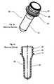
- Fig. 1a shows a perspective view of a container 20 according to the prior art.
- This container 20 has a base body 22 and a thread 24. Between this thread 24 and the base body 22, a support ring 21 and a securing ring 26 are provided.
- This container 20 is expanded to a plastic bottle in the course of the manufacturing process, but the shape including the support ring 21 and above the support ring 21 is maintained in the expansion process. It can be seen that the support ring 21 protrudes substantially radially outward and thus a large amount of material is required for this support ring.
- Fig. 1b shows a cross-sectional view of the in Fig. 1a Since this container is conveyed in a two-stage process with a plurality of gripping clamps, it is possible that a certain gripping clip below the support ring 21 engages and another gripping clip between the lower support ring 21 and the locking ring 26. In this way, an engagement avoided in the thread 24 and this will be spared.
- Fig. 2 shows a cross-sectional view of a container 1 according to the invention, which has an expandable base body 2 and a thread 3. Between the thread 3 and the Base 2 a locking ring 6 is provided. Between the base body 2 and the retaining ring 6, that is below the retaining ring 6, a groove 4 is provided according to the invention, in which, for example, a gripping device for transporting the container 1 can engage.
- This groove 4 in Fig. 2 However, it is also possible to provide a partially broken groove.
- the reference numeral 5 refers to the mouth of the container 1. Starting from the outer periphery of this mouth, the thread 3 extends.
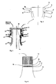
- Fig. 3 shows a comparison of a container according to the invention (right part of Fig. 3 ) and a container of the prior art (left part of Fig. 3 ), wherein here also a closure 12 of the container is indicated.
- the thread is the same in each case.
- any standard container and in particular any common mouthpiece can be modified by the principle according to the invention.
- the closure 12 has a securing band 14 which engages below the securing ring 6 in both variants (both in the prior art and in the embodiment according to the invention).
- Fig. 2 and Fig. 3 can be seen that the groove 4 is formed with respect to the retaining ring 6 and the base body 2 and pulled inwards.
- This Circlip 6 has according to Fig. 2 an upper radially outwardly extending portion 6a, a lower radially outward portion 6c, and an inclined portion 6b.
- a gripping device can engage in the groove 4 and thus a direct contact with the thread of the thread 3 is prevented.
- the groove is formed here by a vertically extending groove bottom 4b, an upper radial wall portion 4a and a lower radial wall portion 4c.
- the wall thickness of the container below the securing ring 6 is preferably between 1.5 mm and 5 mm, preferably between 2 mm and 4 mm and particularly preferably about 3 mm.
- Fig. 4 is a side view of an inventive container, which is additionally provided with a closure lid 12 is shown. It can easily be seen that it can be achieved through the groove 4 that, in the context of the manufacturing process or transportation, the closeable area of the thread is not touched and, in particular, is not touched radially from the outside, and thus deformations of this area are avoided.
- the groove 4 has at its groove bottom 4b a structure, here in the form of a longitudinal corrugation, on.
- the depth of the circumferential groove 4 is based on the minimum mouthpiece diameter which one is willing to accept.
- the groove 4 should in particular be so large or so be chosen deep that a secure function of the clamp systems used is guaranteed. Due to the omission of the support ring according to the invention, the problem may arise in individual cases that there is no longer any support ring which protects the securing band 14 of a bottle closure 12 from reaching underneath. In this way, manipulation of this security band could be facilitated. To maintain this security, it would be possible to attach the sealed mouthpiece or to arrange it with a sleeve on the container. More specifically, a shrink wrap could be placed over the top of the bottle.
- container 1 engages a first gripping device below the securing ring 6 and can pass the container, for example, to a further gripping device which engages in the groove 4.
- a device according to the invention for transporting such containers can be used, for example, in blow molding machines, labeling machines, filling machines, heaters for the containers and the like.
- the base body 2 has a tapered region. This taper can be made lower in the container according to the invention than in containers according to the prior art, since even in the region of the groove 4, a taper takes place.
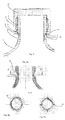
- Fig. 5 shows a further embodiment of a container according to the invention.
- the retaining ring is not formed as a respect to the outer circumference 7 projecting ring but the locking ring closes in the radial direction with the outer circumference 7 of Mouth off.
- the securing band can snap under the outer circumference 7 of the mouth and therefore the underside of the outer circumference 7 itself acts as a securing ring.
- FIG. 5 two embodiments of the area below the locking ring 6 are shown.
- a further groove 11 is provided, in which engages a portion of the security band.
- a two-step shoulder 18, the lower step of which forms the groove 4 is provided.
- the upper step 19 here engages the backup tape of the closure or the portion 13 of the backup tape.
- the upper step or constriction 19 has two functions. First, as noted, snaps securing band into this constriction so that the closure can not be removed from the bottle nondestructively. Furthermore, the bottle retaining clips of the transfer stars can also engage in this upper step or constriction.
- the second stage or groove 4 serves as an engagement for the bottle holding clamps.
- FIG. 6a Shown grooves 4d or other contours may be formed in the groove or the groove bottom, which increase the frictional or positive locking. Also, as in Fig. 6c shown distributed over the circumference of the groove bottom as contour acting projections 13 may be arranged.
Landscapes
- Engineering & Computer Science (AREA)
- Ceramic Engineering (AREA)
- Mechanical Engineering (AREA)
- Containers Having Bodies Formed In One Piece (AREA)
- Closures For Containers (AREA)
Abstract
Description
- Die vorliegende Erfindung betrifft ein Behältnis, beispielsweise eine Kunststoffflasche, zur Aufbewahrung von Flüssigkeiten oder Getränken, gemäß dem Oberbegriff des Schutzanspruches 1. Derartige Kunststoffbehältnisse umfassen insbesondere PET-Flaschen, welche mittels eines thermischen Verfahrens aus einer PET-Preform hergestellt werden. Sie werden seit Mitte der 1990er Jahre unter anderem als Verpackungsmittel in der Getränkeindustrie zunehmend eingesetzt. Unter dem Begriff Behältnis wird neben der eigentlichen Flasche auch der Preform bzw. Vorformling verstanden.
- Um die einzelnen Behältnisse bzw. Preforms handhaben und behandeln zu können, weisen diese im Stand der Technik einen meist umlaufenden Kragen auf. Dieser ringförmige Kragen wird verwendet, um das Behältnis beispielsweise mit einem Greifarm zu greifen und an einen weiteren Greifarm weitergeben zu können. Insbesondere wird dieser auch als Tragring bezeichnete Kragen zum Handling einer Flasche verwendet. Dabei wird in der Regel von einer Klammer, welche das Behältnis umgreift, zur nächsten gewechselt, wobei eine Klammer unterhalb des Tragringes greift und eine Klammer oberhalb des Tragringes zwischen dem Tragring und einem meist oberhalb des Tragrings angeordneten Sicherungsring greift. Dieser Sicherungsring ist gegenüber dem Tragring wesentlich kleiner und somit auch materialsparender ausgebildet.
- Damit dient ein solcher Tragring, der üblicherweise auch im fertigen Produkt sichtbar ist, ausschließlich dem Herstellungs- und Befüllungsprozess der Behältnisse. Andererseits benötigt dieser Tragring auch eine erhebliche Menge an Kunststoffmaterial. Dabei ist insbesondere zu beachten, dass eine Preform in demjenigen Bereich, in dem dieser Tragring angeordnet ist, unverstreckt bleibt und damit eine große Menge an Material in dem Tragring verbleibt.
- Aus der Druckschrift
DE 20 2007 009 983 U1 , deren Offenbarung durch Bezugnahme vollständig in vorliegende Schrift aufgenommen wird, ist bereits ein Behältnis bekannt, welches einen Grundkörper und ein Gewinde aufweist, bei welchem ein wenigstens abschnittsweise umlaufender Sicherungsring vorgesehen ist, der sich bezüglich des Grundkörpers des Behältnisses nach außen erstreckt, wobei der wenigstens abschnittsweise umlaufende Sicherungsring in einer Längsrichtung des Behältnisses zwischen dem Gewinde und dem Grundkörper angeordnet und in der Längsrichtung des Behältnisses von dem Gewinde beabstandet ist. Dabei weist das Behältnis insbesondere zwischen dem Grundkörper und dem umlaufenden Sicherungsring eine wenigstens abschnittsweise umlaufende Nut auf, wobei diese Nut einen geringeren Außenquerschnitt als der Sicherungsring und einen geringeren Außenquerschnitt als das Gewinde aufweist. - Der vorliegenden Erfindung liegt daher die Aufgabe zugrunde, ein Behältnis zur Verfügung zu stellen, welches eine höhere Materialeinsparung erlaubt und insbesondere ein Behältnis zur Verfügung zu stellen, welches auf den erwähnten Tragring verzichtet.
- Diese Aufgabe wird gemäß den Merkmalen des Schutzanspruches 1 gelöst. Vorteilhafte Ausführungsformen und Weiterbildungen sind Gegenstand der Unteransprüche.
- Das erfindungsgemäße Behältnis besteht aus einem Grundkörper und einer Mündung, einem an einem Außenumfang der Mündung angeordneten Gewinde, wobei unterhalb des Gewindes ein sich bezüglich des Außenumfangs der Mündung wenigstens gleich weit nach außen erstreckender Sicherungsring angeordnet ist, und einer wenigstens abschnittsweise umlaufenden Nut. Dabei ist die Nut erfindungsgemäß zwischen dem Aussenumfang der Mündung und dem Sicherungsring vorgesehen und weist einen geringeren Außenquerschnitt als das Gewinde auf.
- Der Sicherungsring erstreckt sich dabei im Wesentlichen radial nach außen. Der Sicherungsring dient vorzugsweise auch gleichzeitig dazu, um beim Öffnen der Flasche eine Versiegelung des Flaschenverschlusses zu öffnen.
- Dabei ist es möglich, dass sich der Sicherungsring in radialer Richtung über den Aussenumfang hinaus nach aussen erstreckt, es wäre jedoch auch möglich, dass der Sicherungsring einteilig mit dem Aussenumfang ausgebildet ist bzw. in der radialen Richtung bündig mit dem Aussenumfang abschließt In diesem Fall kann das Sicherungsband unterhalb des Sicherungsrings in eine entsprechende Nut eingreifen. Mit anderen Worten übernimmt hier der Aussenumfang bzw. dessen dem Grundkörper zugewandter Bereich die Funktion des Sicherungsrings. Vorzugsweise ist hier der Sicherungsring ein Bestandteil bzw. Abschnitt des Aussenumfangs. Es wäre auch möglich, dass der Sicherungsring gegenüber dem Aussenumfang in radialer Richtung geringfügig zurückgezogen ist.
- Durch das Vorsehen dieser Nut ist es möglich, dass mit einem speziell angepassten Eingriffsmittel in diese Nut eingegriffen wird, um das Behältnis zu transportieren oder allgemein zu behandeln und dass durch diesen Eingriff das Gewinde selbst nicht beschädigt wird. Dabei liegt das Eingriffsmittel bevorzugt von unten her am Gewindekern an, so dass der Gewindegang selbst nicht berührt wird. Darüber hinaus erübrigt sich aufgabengemäß die Einarbeitung eines Kragens bzw. Tragringes.
- Vorzugsweise ist unterhalb des Gewindes kein sich über den Außenquerschnitt des Gewindes hinaus erstreckende Element vorgesehen.
- Weiterhin bevorzugt ist unterhalb des Gewindes und des Sicherungsringes kein weiteres sich nach außen über den Außenquerschnitt des Gewindes hinaus erstreckendes, umlaufendes Element angeordnet.
- Bevorzugt ist das Behältnis, wie erwähnt, aus Kunststoff hergestellt.
- Vorzugsweise weist die Nut einen geringeren Außenquerschnitt als die Mündung auf. Damit weist besonders bevorzugt das Behältnis entlang seiner Längsrichtung im Bereich der Nut vollumfänglich einen geringeren Außenumfang auf.
- Daher ist das erfindungsgemäße Behältnis derart ausgestattet, dass es von unterschiedlichen Greifeinrichtungen auf unterschiedlichen Höhen in Längsrichtung des Behältnisses gegriffen werden kann, ohne dass dabei das Gewinde selbst berührt bzw. beschädigt wird. Insbesondere wird durch die Nut erreicht, dass das Behältnis auf einer genau definierten Höhe gegriffen wird.
- Vorzugsweise ist die Nut vom Sicherungsring derart beabstandet, dass beispielsweise ein Verschlußdeckel über den Sicherungsring hinausragen kann, die Nut aber vom Verschlussdeckel unbedeckt bleibt. Damit kann beispielsweise eine Greifeinrichtung auch ein bereits mit einem Verschlußdeckel verschlossenes Behältnis greifen und transportieren.
- Bevorzugt weist die Nut wenigstens abschnittsweise geradlinig verlaufende Begrenzungswände auf. Damit ist ein präziser Eingriff einer Greifeinrichtung in die Nut und somit ein stabiler Halt des Behältnisses während eines Transportvorganges gewährleistet.
- Dies wird vorzugsweise dadurch unterstützt, in dem die Nut im Querschnitt die Gestalt eines offenen Rechtecks bzw. zwei rechte Winkel aufweist.
- Das Behältnis weist bevorzugt eine Innenwandung auf, welche in Längsrichtung des Behältnisses mindestens eine Verjüngung aufweist, wobei sich besonders bevorzugt der Innenquerschnitt der Verjüngung kontinuierlich verändert. Diese Verjüngung ist bevorzugt in dem Bereich der Nut vorgesehen.
- Zudem ist die Nut im Bereich Ihres Außenumfangs bzw. des Nutgrundes vorzugsweise strukturiert, wobei die Oberfläche des Außenumfangbereichs der Nut beispielsweise eine Längsriffelung aufweisen kann, die einer Greifeinrichtung ein sicheres und stabiles Eingreifen in die Nut erlaubt Weiterhin weist das Behältnis vorzugsweise einen Verschluß auf, welcher in geschlossenem Zustand oberhalb der Nut abschließt. Damit kann beispielsweise eine Greifeinrichtung auch ein bereits mit einem Verschluß verschlossenes Behältnis greifen und transportieren.
- Die vorliegende Erfindung richtet sich weiterhin auf eine Vorrichtung zum Transportieren von Behältnissen der oben beschriebenen Art. Diese Vorrichtung weist mindestens eine erste Greifeinrichtung auf, welche die Behältnisse an einem ersten vorgegebenen Bereich der Behältnisse greift sowie wenigstens eine zweite Greifeinrichtung, welche die Behältnisse an einem zweiten von dem ersten Bereich verschiedenen Bereich der Behältnisse greift. Erfindungsgemäß greift die erste Greifeinrichtung das Behältnis unterhalb des Sicherungsringes und die zweite Greifeinrichtung das Behältnis in der Nut und unterhalb des Sicherungsringes.
- Weitere Vorteile und Zweckmäßigkeiten sind der nachfolgenden Beschreibung in Verbindung mit den Zeichnungen zu entnehmen. Hierbei zeigen:
- Fig. 1a
- ein Behältnis nach dem Stand der Technik;
- Fig. 1b
- eine Querschnittsansicht eines Behältnisses nach dem Stand der Technik;
- Fig. 2
- einen Querschnitt eines erfindungsgemäßen Behältnisses;
- Fig. 3
- eine Gegenüberstellung eines Behältnisses nach dem Stand der Technik und eines erfindungsgemäßen Behältnisses;
- Fig. 4
- eine Seitenansicht eines erfindungsgemäßen Behältnisses;
- Fig. 5
- eine weitere Ausführungsform eines erfindungsgemäßen Behältnisses;
- Fig. 6a-c
- zwei Darstellungen einer Nut.
-
Fig. 1a zeigt eine perspektivische Ansicht eines Behältnisses 20 nach dem Stand der Technik. Dieses Behältnis 20 weist einen Grundkörper 22 und ein Gewinde 24 auf. Zwischen diesem Gewinde 24 und dem Grundkörper 22 sind ein Tragring 21 und ein Sicherungsring 26 vorgesehen. Dieses Behältnis 20 wird im Laufe des Herstellungsverfahrens zu einer Kunststoffflasche expandiert, wobei jedoch die Gestalt einschließlich des Tragrings 21 und oberhalb des Tragrings 21 bei dem Expansionsvorgang beibehalten bleibt. Man erkennt, dass der Tragring 21 erheblich radial nach außen ragt und damit eine große Menge an Material für diesen Tragring erforderlich ist. -
Fig. 1b zeigt eine Querschnittsansicht des inFig. 1a gezeigten Behältnisses 20. Da dieses Behältnis in einem zweistufigen Verfahren mit mehreren Greifklammern befördert wird, ist es möglich, dass eine bestimmte Greifklammer unterhalb des Tragrings 21 eingreift und eine weitere Greifklammer zwischen dem unteren Tragring 21 und dem Sicherungsring 26. Auf diese Weise kann ein Eingriff in das Gewinde 24 vermieden und dieses damit geschont werden. -
Fig. 2 zeigt eine Querschnittsansicht eines erfindungsgemäßen Behältnisses 1, welches einen expandierbaren Grundkörper 2 und ein Gewinde 3 aufweist. Zwischen dem Gewinde 3 und dem Grundkörper 2 ist ein Sicherungsring 6 vorgesehen. Zwischen dem Grundkörper 2 und dem Sicherungsring 6, also unterhalb des Sicherungsringes 6, ist erfindungsgemäß eine Nut 4 vorgesehen, in die beispielsweise eine Greifeinrichtung zum Transport des Behältnisses 1 greifen kann. Damit ist es möglich, bei der erfindungsgemäßen Ausführungsform auf das Vorsehen eines Tragrings, wie im Stand der Technik, zu verzichten. Es wird darauf hingewiesen, dass diese Nut 4 inFig. 2 umlaufend ausgeführt ist, es ist jedoch auch möglich, eine teilweise unterbrochene Nut vorzusehen. Das Bezugszeichen 5 bezieht sich auf die Mündung des Behältnisses 1. Ausgehend von dem Außenumfang dieser Mündung erstreckt sich das Gewinde 3. -
Fig. 3 zeigt eine Gegenüberstellung eines erfindungsgemäßen Behältnisses (rechter Teil vonFig. 3 ) und eines Behältnisses nach dem Stand der Technik (linker Teil vonFig. 3 ), wobei hier auch ein Verschluss 12 des Behältnisses angedeutet ist. Man erkennt, dass bei beiden Varianten das Gewinde jeweils gleich ausgeführt ist. Es wird in diesem Zusammenhang darauf hingewiesen, dass sich grundsätzlich jedes gängige Behältnis und insbesondere jedes gängige Mundstück durch das erfindungsgemäße Prinzip modifizieren lässt. Dies bedeutet, dass auch auf das erfindungsgemäße Behältnis die frei am Markt verfügbaren Schraubverschlüsse angebracht werden können. Der Verschluß 12 weist ein Sicherungsband 14 auf, der bei beiden Varianten (sowohl beim Stand der Technik als auch bei der erfindungsgemäßen Ausführungsform) unterhalb des Sicherungsrings 6 eingreift. - Ferner ist
Fig. 2 und Fig. 3 zu entnehmen, dass die Nut 4 gegenüber dem Sicherungsring 6 und dem Grundkörper 2 ausgebildet bzw. nach innen gezogen ist. Dieser Sicherungsring 6 weist gemäßFig. 2 einen oberen radial nach außen verlaufenden Abschnitt 6a, einen unteren radial nach außen verlaufenden Abschnitt 6c sowie einen schräg verlaufenden Abschnitt 6b auf. Zum Transport der Behältnisse kann eine Greifeinrichtung in die Nut 4 eingreifen und damit wird ein direkter Kontakt mit dem Gewindegang des Gewindes 3 verhindert. Die Nut wird hier durch einen vertikal verlaufenden Nutgrund 4b, einen oberen radial verlaufenden Wandabschnitt 4a und einen unteren radial verlaufenden Wandabschnitt 4c gebildet. - In demjenigen Bereich, in dem die Nut 4 vorgesehen ist, ist der Behältnis - Innendurchmesser verringert, bzw. weist eine Verjüngung 16 auf, um in allen Bereichen des Behältnisses eine ausreichende Wanddicke zur Verfügung zu haben. Die Wanddicke des Behältnisses unterhalb des Sicherungsrings 6 liegt bevorzugt zwischen 1,5 mm und 5 mm, bevorzugt zwischen 2 mm und 4 mm und besonders bevorzugt bei ca. 3 mm.
- In
Fig. 4 ist in einer Seitenansicht ein erfindungsgemäßes Behältnis, welches zusätzlich mit einem Verschlussdeckel 12 versehen ist, dargestellt. Es ist leicht erkennbar, dass durch die Nut 4 erreicht werden kann, dass im Rahmen des Herstellungsverfahrens oder des Transportes der verschlusssensible Bereich des Gewindes nicht berührt und insbesondere nicht radial von außen berührt wird, und damit Verformungen dieses Bereiches vermieden werden. Die Nut 4 weist an ihrem Nutgrund 4b eine Struktur, hier in Form einer Längsriffelung, auf. - Die Tiefe der umlaufenden Nut 4 orientiert sich an dem minimalen Mundstücksinnendurchmesser, den man bereit ist zu akzeptieren. Die Nut 4 sollte insbesondere so groß bzw. so tief gewählt werden, dass eine sichere Funktion der verwendeten Klammersysteme gewährleistet ist. Durch das erfindungsgemäße Weglassen des Tragrings kann in Einzelfällen das Problem auftreten, dass auch kein Tragring mehr vorhanden ist, der das Sicherungsband 14 eines Flaschenverschlusses 12 vor Untergreifen schützt. Auf diese Weise könnten Manipulationen an diesem Sicherheitsband erleichtert werden. Um diese Sicherheit weiterhin beizubehalten, wäre es möglich, das verschlossene Mundstück anzusleeven bzw. mit einer Hülle an dem Behältnis anzuordnen. Genauer könnte eine Schrumpfhülle über dem Verschluß bzw. dem Kopf der Flasche angeordnet sein.
- Bei einem erfindungsgemäßen Verfahren zum Transport des in
Fig. 2 und 4 gezeigten Behältnisses 1 greift eine erste Greifeinrichtung unterhalb des Sicherungsrings 6 ein und kann das Behältnis beispielsweise an eine weitere Greifeinrichtung übergeben, die in die Nut 4 eingreift. Eine erfindungsgemäße Vorrichtung zum Transportieren von derartigen Behältnissen kann beispielsweise in Blasmaschinen, Etikettiermaschinen, Füllmaschinen, Heizeinrichtungen für die Behältnisse und dergleichen Anwendung finden. Wie inFig. 2 gezeigt, weist auch der Grundkörper 2 einen sich verjüngenden Bereich auf. Diese Verjüngung kann bei dem erfindungsgemäßen Behältnis geringer ausgeführt werden als bei Behältnissen nach dem Stand der Technik, da bereits in dem Bereich der Nut 4 eine Verjüngung stattfindet. -
Fig. 5 zeigt eine weitere Ausführungsform eines erfindungsgemäßen Behältnisses. Bei dieser Ausführungsform ist der Sicherungsring nicht als gegenüber dem Aussenumfang 7 hervorstehender Ring ausgebildet sondern der Sicherungsring schließt in radialer Richtung mit dem Aussenumfang 7 der Mündung ab. Dies bedeutet, dass hier das Sicherungsband unterhalb des Aussenumfangs 7 der Mündung einschnappen kann und daher die Unterseite des Aussenumfangs 7 selbst als Sicherungsring wirkt. - In
Figur 5 sind zwei Ausgestaltungen des Bereiches unterhalb des Sicherungsrings 6 dargestellt. Bei der auf der linken Seite der Figur gezeigten Ausführungsform ist unterhalb des (hier den Sicherungsring bildenden) Aussenumfangs neben der Nut 4, welche für den Eingriff der Greifklammer dient, eine weitere Nut 11 vorgesehen, in welche ein Abschnitt des Sicherungsbandes eingreift. - Bei der auf der rechten Seite gezeigten Ausgestaltung ist ein zweistufiger Absatz 18, dessen untere Stufe die Nut 4 ausbildet, vorgesehen. In die obere Stufe 19 greift hier das Sicherungsband des Verschlusses bzw. der Abschnitt 13 des Sicherungsbandes ein. Die obere Stufe bzw. Einschnürung 19 hat dabei zwei Funktionen. Erstens schnappt, wie erwähnt, dass Sicherungsband in diese Einschnürung ein, so dass der Verschluss nicht zerstörungsfrei von der Flasche entfernt werden kann. Weiterhin können in diese obere Stufe bzw. Einschnürung auch die Flaschenhalteklammern der Transfersterne eingreifen.
- Die zweite Stufe bzw. die Nut 4 dient als Eingriff für die Flaschenhalteklammern.
- Die
Figuren 6a - 6c zeigen drei weitere Darstellungen der unteren Ausnehmung bzw. der Nut 4. Optional ist es möglich, in die zweite Abstufung d.h. die Nut 4 eine Kontur 4d bzw. ein Profil zu integrieren, die als kraft-, reib- und/oder formschlüssige Verbindung dient, beispielsweise beim Verschließen der als Verdrehsicherung wirkt. So können, wie inFig. 6b gezeigt, in der Nut bzw. dem Nutgrund Rillen 4d oder sonstige Konturen ausgebildet sein, welche den Reib- bzw. Formschluss erhöhen. Auch könnten, wie inFig. 6c gezeigt, über den Umfang des Nutgrunds verteilt als Kontur wirkende Vorsprünge 13 angeordnet sein. - Die Anmelderin behält sich vor, sämtliche in den Anmeldungsunterlagen offenbarten Merkmale als erfindungswesentlich zu beanspruchen, sofern sie einzeln oder in Kombination gegenüber dem Stand der Technik neu sind.
Claims (15)
- Behältnis (1) bestehend aus einem Grundkörper (2) und einer Mündung (5), einem an einem Außenumfang der Mündung (5) angeordneten Gewinde (3), wobei unterhalb des Gewindes (3) ein sich bezüglich des Außenumfangs der Mündung (5) wenigstens gleich weit nach außen erstreckender Sicherungsring (6) angeordnet ist, und einer wenigstens abschnittsweise umlaufenden Nut (4), dadurch gekennzeichnet dass die Nut (4) zwischen dem Grundkörper (2) und dem Sicherungsring (6) vorgesehen ist und einen geringeren Außenquerschnitt als das Gewinde (3) aufweist.
- Behältnis (1) nach Anspruch 1, dadurch gekennzeichnet, dass unterhalb des Gewindes (3) kein sich über den Außenquerschnitt des Gewindes (3) hinaus erstreckendes Element vorgesehen ist.
- Behältnis (1) nach Anspruch 2, dadurch gekennzeichnet, dass unterhalb des Gewindes (3) und des Sicherungsringes (6) kein weiteres sich nach außen über den Außenquerschnitt des Gewindes (3) hinaus erstreckendes, umlaufendes Element angeordnet ist.
- Behältnis (1) nach wenigstens einem der vorangegangenen Ansprüche, dadurch gekennzeichnet, dass das Behältnis (1) aus Kunststoff hergestellt ist.
- Behältnis (1) nach wenigstens einem der vorangegangenen Ansprüche, dadurch gekennzeichnet, dass die Nut (4) einen geringeren Außenquerschnitt als die Mündung (5) aufweist.
- Behältnis (1) nach wenigstens einem der vorangegangenen Ansprüche, dadurch gekennzeichnet, dass die Nut (4) vom Sicherungsring (6) beabstandet ist.
- Behältnis (1) nach wenigstens einem der vorangegangenen Ansprüche, dadurch gekennzeichnet, dass die Nut (4) wenigstens abschnittsweise geradlinig verlaufende Begrenzungswände (4a, 4b, 4c) aufweist.
- Behältnis (1) nach wenigstens einem der vorangegangenen Ansprüche, dadurch gekennzeichnet, dass die Nut (4) die Gestalt eines offenen Rechtecks aufweist.
- Behältnis (1) nach wenigstens einem der vorangegangenen Ansprüche, dadurch gekennzeichnet, dass das Behältnis (1) eine Innenwandung aufweist, welche in Längsrichtung des Behältnisses (1) mindestens eine Verjüngung (16) aufweist.
- Behältnis (1) nach Anspruch 9, dadurch gekennzeichnet, dass sich der Innenquerschnitt der Verjüngung (16) kontinuierlich verändert.
- Behältnis (1) nach wenigstens einem der vorangegangenen Ansprüche, dadurch gekennzeichnet, dass die Nut (4) im Bereich Ihres Außenumfangs strukturiert ist.
- Behältnis (1) nach wenigstens einem der vorangegangenen Ansprüche, dadurch gekennzeichnet, dass das Behältnis (1) einen Verschluss (12) aufweist, welcher in geschlossenem Zustand oberhalb der Nut (4) abschließt.
- Behältnis nach wenigstens einem der vorangegangenen Ansprüche, dadurch gekennzeichnet, dass der Sicherungsring (6) ein Abschnitt des Aussenumfangs ist.
- Behältnis nach wenigstens einem der vorangegangenen Ansprüche, dadurch gekennzeichnet, dass unterhalb des Aussenumfangs neben der Nut (4) eine weitere Nut oder eine zweistufige Nut(18) vorgesehen ist, wobei die untere Stufe dieser zweistufigen Nut die Nut (4) ist
- Vorrichtung zum Transportieren von Behältnissen (1) nach wenigstens einem der Ansprüche 1-14, mit einer ersten Greifeinrichtung, welche das Behältnis (1) an einem ersten vorgegebenen Bereich des Behältnisses (1) greift und wenigstens einer zweiten Greifeinrichtung, welche das Behältnis (1) an einem zweiten von dem ersten Bereich verschiedenen Bereich des Behältnisses (1) greift, dadurch gekennzeichnet, dass die erste Greifeinrichtung derart gestaltet ist, dass diese das Behältnis (1) unterhalb des Sicherungsringes (6) greift und die zweite Greifeinrichtung derart gestaltet ist, dass diese das Behältnis (1) in der Nut (4) des Behältnisses greift.
Priority Applications (1)
| Application Number | Priority Date | Filing Date | Title |
|---|---|---|---|
| EP16175580.6A EP3098175A1 (de) | 2009-01-23 | 2010-01-22 | Behältnis mit mündungsnut |
Applications Claiming Priority (1)
| Application Number | Priority Date | Filing Date | Title |
|---|---|---|---|
| DE102009006004A DE102009006004A1 (de) | 2009-01-23 | 2009-01-23 | Behältnis mit Mündungsnut |
Related Child Applications (1)
| Application Number | Title | Priority Date | Filing Date |
|---|---|---|---|
| EP16175580.6A Division EP3098175A1 (de) | 2009-01-23 | 2010-01-22 | Behältnis mit mündungsnut |
Publications (3)
| Publication Number | Publication Date |
|---|---|
| EP2210816A1 true EP2210816A1 (de) | 2010-07-28 |
| EP2210816A8 EP2210816A8 (de) | 2011-03-16 |
| EP2210816B1 EP2210816B1 (de) | 2016-06-22 |
Family
ID=40561268
Family Applications (2)
| Application Number | Title | Priority Date | Filing Date |
|---|---|---|---|
| EP16175580.6A Withdrawn EP3098175A1 (de) | 2009-01-23 | 2010-01-22 | Behältnis mit mündungsnut |
| EP10151359.6A Active EP2210816B1 (de) | 2009-01-23 | 2010-01-22 | Behältnis mit Mündungsnut |
Family Applications Before (1)
| Application Number | Title | Priority Date | Filing Date |
|---|---|---|---|
| EP16175580.6A Withdrawn EP3098175A1 (de) | 2009-01-23 | 2010-01-22 | Behältnis mit mündungsnut |
Country Status (3)
| Country | Link |
|---|---|
| EP (2) | EP3098175A1 (de) |
| CN (1) | CN101786515B (de) |
| DE (2) | DE202009001417U1 (de) |
Cited By (1)
| Publication number | Priority date | Publication date | Assignee | Title |
|---|---|---|---|---|
| US20220281152A1 (en) * | 2019-09-27 | 2022-09-08 | Nissei Asb Machine Co., Ltd. | Method for producing resin container and device for producing resin container |
Families Citing this family (1)
| Publication number | Priority date | Publication date | Assignee | Title |
|---|---|---|---|---|
| CH707062A1 (de) * | 2012-10-04 | 2014-04-15 | Alpla Werke | Supportringloser Kunststoffbehälter, insbesondere Kunststoffflasche. |
Citations (7)
| Publication number | Priority date | Publication date | Assignee | Title |
|---|---|---|---|---|
| DE7514598U (de) * | 1975-05-07 | 1975-11-06 | Raku Kunststoff Verpackungswer | Weithalsgefaess aus thermoplastischem Kunststoff |
| US20040108295A1 (en) * | 2002-12-06 | 2004-06-10 | Schumann Ronald C. | Retortable plastic container |
| US20070080128A1 (en) * | 2005-10-10 | 2007-04-12 | Laveault Richard A | Beverage container with threaded plastic drinking sleeve |
| DE102005051735A1 (de) * | 2005-10-28 | 2007-05-03 | Krones Ag | Kunststoffbehälter sowie Verfahren zu seiner Herstellung und Verfahren zu seiner Handhabung |
| DE202007009983U1 (de) | 2007-07-17 | 2007-10-31 | Krones Ag | Kunststoffbehältnis mit Eingriffsnut |
| WO2008095842A1 (en) * | 2007-02-07 | 2008-08-14 | Nestle Waters Management & Technology | Lightweight container |
| EP2100707A1 (de) * | 2008-03-13 | 2009-09-16 | La Seda De Barcelona S.A. | Kunststoffvorformling mit leichtgewichtigem und verschließbarem Hals |
Family Cites Families (4)
| Publication number | Priority date | Publication date | Assignee | Title |
|---|---|---|---|---|
| AT5071U1 (de) * | 2000-04-10 | 2002-03-25 | Kosme Gmbh | Vorformling zur herstellung von hohlkörpern |
| US7168581B2 (en) * | 2001-12-21 | 2007-01-30 | Rexam Medical Packaging Inc. | Closure for a retort processed container having a peelable seal |
| US20070045216A1 (en) * | 2005-08-03 | 2007-03-01 | Graham Packaging Company, L.P. | Plastic container finish with structural rib |
| ITRM20070552A1 (it) * | 2007-10-23 | 2009-04-24 | Acqua Minerale S Benedetto S P | Contenitore in materiale plastico |
-
2009
- 2009-01-23 DE DE202009001417U patent/DE202009001417U1/de not_active Expired - Lifetime
- 2009-01-23 DE DE102009006004A patent/DE102009006004A1/de not_active Ceased
-
2010
- 2010-01-22 EP EP16175580.6A patent/EP3098175A1/de not_active Withdrawn
- 2010-01-22 EP EP10151359.6A patent/EP2210816B1/de active Active
- 2010-01-25 CN CN201010113231.5A patent/CN101786515B/zh active Active
Patent Citations (7)
| Publication number | Priority date | Publication date | Assignee | Title |
|---|---|---|---|---|
| DE7514598U (de) * | 1975-05-07 | 1975-11-06 | Raku Kunststoff Verpackungswer | Weithalsgefaess aus thermoplastischem Kunststoff |
| US20040108295A1 (en) * | 2002-12-06 | 2004-06-10 | Schumann Ronald C. | Retortable plastic container |
| US20070080128A1 (en) * | 2005-10-10 | 2007-04-12 | Laveault Richard A | Beverage container with threaded plastic drinking sleeve |
| DE102005051735A1 (de) * | 2005-10-28 | 2007-05-03 | Krones Ag | Kunststoffbehälter sowie Verfahren zu seiner Herstellung und Verfahren zu seiner Handhabung |
| WO2008095842A1 (en) * | 2007-02-07 | 2008-08-14 | Nestle Waters Management & Technology | Lightweight container |
| DE202007009983U1 (de) | 2007-07-17 | 2007-10-31 | Krones Ag | Kunststoffbehältnis mit Eingriffsnut |
| EP2100707A1 (de) * | 2008-03-13 | 2009-09-16 | La Seda De Barcelona S.A. | Kunststoffvorformling mit leichtgewichtigem und verschließbarem Hals |
Cited By (2)
| Publication number | Priority date | Publication date | Assignee | Title |
|---|---|---|---|---|
| US20220281152A1 (en) * | 2019-09-27 | 2022-09-08 | Nissei Asb Machine Co., Ltd. | Method for producing resin container and device for producing resin container |
| US11958230B2 (en) * | 2019-09-27 | 2024-04-16 | Nissei Asb Machine Co., Ltd. | Method for producing resin container and device for producing resin container |
Also Published As
| Publication number | Publication date |
|---|---|
| EP2210816A8 (de) | 2011-03-16 |
| CN101786515A (zh) | 2010-07-28 |
| DE202009001417U1 (de) | 2009-04-16 |
| CN101786515B (zh) | 2014-12-10 |
| EP2210816B1 (de) | 2016-06-22 |
| EP3098175A1 (de) | 2016-11-30 |
| DE102009006004A1 (de) | 2010-07-29 |
Similar Documents
| Publication | Publication Date | Title |
|---|---|---|
| DE102007033621B4 (de) | Kunststoffbehältnis mit Eingriffsnut | |
| DE19909308B4 (de) | KunststoffvVerschlußkappe mit abtrennbarem Garantieband und Innendichtung | |
| DE69502134T2 (de) | Verbesserung des Verfahrens zum Herstellen einer Verschlussvorrichtung und Maschine dafür | |
| DE3006773C2 (de) | Garantie-Verschlußkappe | |
| DE60214501T2 (de) | Garantieverschluss und Behälter mit Vorkehrungen zum Ableiten von Flüssigkeiten und Verfahren zu deren Herstellung | |
| DE2910178C2 (de) | Originalitäts-Schraubverschluß für Flaschen u.dgl | |
| DE202007009983U1 (de) | Kunststoffbehältnis mit Eingriffsnut | |
| EP2892701B1 (de) | Preform zur herstellung von kunststoffbehältern in einem streckblasverfahren | |
| DE3231859C2 (de) | In einem Arbeitsgang hergestellter, gefüllter und verschlossener, blasgeformter, flaschenförmiger Behälter | |
| EP2566768B1 (de) | Behältnis mit schraubverschluss | |
| DE3621575A1 (de) | Behaelter mit originalitaetsverschluss | |
| EP3279115B1 (de) | Verfahren zur herstellung eines behälterverschluss-systems | |
| DE1942312C3 (de) | Durch axiales Aufpressen auf den Hals einer Flasche aufbringbare Verschlußkappe | |
| EP2601112A1 (de) | Schraubverschluss mit flexband | |
| EP3187430B1 (de) | Supportringloser kunststoffbehälter, insbesondere kunststoffflasche | |
| EP2210816B1 (de) | Behältnis mit Mündungsnut | |
| DE3723235A1 (de) | Garantieverschluss | |
| DE3233806C2 (de) | ||
| EP0270621B1 (de) | Garantieverschluss | |
| DE2856433A1 (de) | Verschluss fuer behaelter | |
| DE102007024849A1 (de) | Chemikalienflasche für druckaufbauende Füllgüter | |
| CH716074A1 (de) | Verschlusskappe zum Verschliessen eines Behälters und Behälter mit einer solchen unverlierbar gehaltenen Verschlusskappe. | |
| DE8709690U1 (de) | Garantieverschluß | |
| AT503350B1 (de) | Vorformling, insbesondere hohlkörper-spritzformling | |
| EP2025604B1 (de) | Verfahren zur Herstellung und Befüllung von Behältern |
Legal Events
| Date | Code | Title | Description |
|---|---|---|---|
| PUAI | Public reference made under article 153(3) epc to a published international application that has entered the european phase |
Free format text: ORIGINAL CODE: 0009012 |
|
| AK | Designated contracting states |
Kind code of ref document: A1 Designated state(s): AT BE BG CH CY CZ DE DK EE ES FI FR GB GR HR HU IE IS IT LI LT LU LV MC MK MT NL NO PL PT RO SE SI SK SM TR |
|
| 17P | Request for examination filed |
Effective date: 20110126 |
|
| 17Q | First examination report despatched |
Effective date: 20120621 |
|
| GRAP | Despatch of communication of intention to grant a patent |
Free format text: ORIGINAL CODE: EPIDOSNIGR1 |
|
| INTG | Intention to grant announced |
Effective date: 20160105 |
|
| GRAS | Grant fee paid |
Free format text: ORIGINAL CODE: EPIDOSNIGR3 |
|
| GRAA | (expected) grant |
Free format text: ORIGINAL CODE: 0009210 |
|
| AK | Designated contracting states |
Kind code of ref document: B1 Designated state(s): AT BE BG CH CY CZ DE DK EE ES FI FR GB GR HR HU IE IS IT LI LT LU LV MC MK MT NL NO PL PT RO SE SI SK SM TR |
|
| REG | Reference to a national code |
Ref country code: GB Ref legal event code: FG4D Free format text: NOT ENGLISH |
|
| REG | Reference to a national code |
Ref country code: CH Ref legal event code: EP |
|
| REG | Reference to a national code |
Ref country code: IE Ref legal event code: FG4D Free format text: LANGUAGE OF EP DOCUMENT: GERMAN |
|
| REG | Reference to a national code |
Ref country code: AT Ref legal event code: REF Ref document number: 807516 Country of ref document: AT Kind code of ref document: T Effective date: 20160715 |
|
| REG | Reference to a national code |
Ref country code: DE Ref legal event code: R096 Ref document number: 502010011858 Country of ref document: DE |
|
| REG | Reference to a national code |
Ref country code: LT Ref legal event code: MG4D |
|
| REG | Reference to a national code |
Ref country code: NL Ref legal event code: MP Effective date: 20160622 |
|
| PG25 | Lapsed in a contracting state [announced via postgrant information from national office to epo] |
Ref country code: LT Free format text: LAPSE BECAUSE OF FAILURE TO SUBMIT A TRANSLATION OF THE DESCRIPTION OR TO PAY THE FEE WITHIN THE PRESCRIBED TIME-LIMIT Effective date: 20160622 Ref country code: FI Free format text: LAPSE BECAUSE OF FAILURE TO SUBMIT A TRANSLATION OF THE DESCRIPTION OR TO PAY THE FEE WITHIN THE PRESCRIBED TIME-LIMIT Effective date: 20160622 Ref country code: NO Free format text: LAPSE BECAUSE OF FAILURE TO SUBMIT A TRANSLATION OF THE DESCRIPTION OR TO PAY THE FEE WITHIN THE PRESCRIBED TIME-LIMIT Effective date: 20160922 |
|
| PG25 | Lapsed in a contracting state [announced via postgrant information from national office to epo] |
Ref country code: LV Free format text: LAPSE BECAUSE OF FAILURE TO SUBMIT A TRANSLATION OF THE DESCRIPTION OR TO PAY THE FEE WITHIN THE PRESCRIBED TIME-LIMIT Effective date: 20160622 Ref country code: NL Free format text: LAPSE BECAUSE OF FAILURE TO SUBMIT A TRANSLATION OF THE DESCRIPTION OR TO PAY THE FEE WITHIN THE PRESCRIBED TIME-LIMIT Effective date: 20160622 Ref country code: SE Free format text: LAPSE BECAUSE OF FAILURE TO SUBMIT A TRANSLATION OF THE DESCRIPTION OR TO PAY THE FEE WITHIN THE PRESCRIBED TIME-LIMIT Effective date: 20160622 Ref country code: GR Free format text: LAPSE BECAUSE OF FAILURE TO SUBMIT A TRANSLATION OF THE DESCRIPTION OR TO PAY THE FEE WITHIN THE PRESCRIBED TIME-LIMIT Effective date: 20160923 Ref country code: HR Free format text: LAPSE BECAUSE OF FAILURE TO SUBMIT A TRANSLATION OF THE DESCRIPTION OR TO PAY THE FEE WITHIN THE PRESCRIBED TIME-LIMIT Effective date: 20160622 |
|
| REG | Reference to a national code |
Ref country code: FR Ref legal event code: PLFP Year of fee payment: 8 |
|
| PG25 | Lapsed in a contracting state [announced via postgrant information from national office to epo] |
Ref country code: EE Free format text: LAPSE BECAUSE OF FAILURE TO SUBMIT A TRANSLATION OF THE DESCRIPTION OR TO PAY THE FEE WITHIN THE PRESCRIBED TIME-LIMIT Effective date: 20160622 Ref country code: CZ Free format text: LAPSE BECAUSE OF FAILURE TO SUBMIT A TRANSLATION OF THE DESCRIPTION OR TO PAY THE FEE WITHIN THE PRESCRIBED TIME-LIMIT Effective date: 20160622 Ref country code: IS Free format text: LAPSE BECAUSE OF FAILURE TO SUBMIT A TRANSLATION OF THE DESCRIPTION OR TO PAY THE FEE WITHIN THE PRESCRIBED TIME-LIMIT Effective date: 20161022 Ref country code: SK Free format text: LAPSE BECAUSE OF FAILURE TO SUBMIT A TRANSLATION OF THE DESCRIPTION OR TO PAY THE FEE WITHIN THE PRESCRIBED TIME-LIMIT Effective date: 20160622 Ref country code: RO Free format text: LAPSE BECAUSE OF FAILURE TO SUBMIT A TRANSLATION OF THE DESCRIPTION OR TO PAY THE FEE WITHIN THE PRESCRIBED TIME-LIMIT Effective date: 20160622 |
|
| PG25 | Lapsed in a contracting state [announced via postgrant information from national office to epo] |
Ref country code: SM Free format text: LAPSE BECAUSE OF FAILURE TO SUBMIT A TRANSLATION OF THE DESCRIPTION OR TO PAY THE FEE WITHIN THE PRESCRIBED TIME-LIMIT Effective date: 20160622 Ref country code: ES Free format text: LAPSE BECAUSE OF FAILURE TO SUBMIT A TRANSLATION OF THE DESCRIPTION OR TO PAY THE FEE WITHIN THE PRESCRIBED TIME-LIMIT Effective date: 20160622 Ref country code: PL Free format text: LAPSE BECAUSE OF FAILURE TO SUBMIT A TRANSLATION OF THE DESCRIPTION OR TO PAY THE FEE WITHIN THE PRESCRIBED TIME-LIMIT Effective date: 20160622 Ref country code: PT Free format text: LAPSE BECAUSE OF FAILURE TO SUBMIT A TRANSLATION OF THE DESCRIPTION OR TO PAY THE FEE WITHIN THE PRESCRIBED TIME-LIMIT Effective date: 20161024 |
|
| REG | Reference to a national code |
Ref country code: DE Ref legal event code: R097 Ref document number: 502010011858 Country of ref document: DE |
|
| PLBE | No opposition filed within time limit |
Free format text: ORIGINAL CODE: 0009261 |
|
| STAA | Information on the status of an ep patent application or granted ep patent |
Free format text: STATUS: NO OPPOSITION FILED WITHIN TIME LIMIT |
|
| 26N | No opposition filed |
Effective date: 20170323 |
|
| PG25 | Lapsed in a contracting state [announced via postgrant information from national office to epo] |
Ref country code: BE Free format text: LAPSE BECAUSE OF NON-PAYMENT OF DUE FEES Effective date: 20170131 Ref country code: DK Free format text: LAPSE BECAUSE OF FAILURE TO SUBMIT A TRANSLATION OF THE DESCRIPTION OR TO PAY THE FEE WITHIN THE PRESCRIBED TIME-LIMIT Effective date: 20160622 |
|
| PG25 | Lapsed in a contracting state [announced via postgrant information from national office to epo] |
Ref country code: SI Free format text: LAPSE BECAUSE OF FAILURE TO SUBMIT A TRANSLATION OF THE DESCRIPTION OR TO PAY THE FEE WITHIN THE PRESCRIBED TIME-LIMIT Effective date: 20160622 |
|
| REG | Reference to a national code |
Ref country code: CH Ref legal event code: PL |
|
| GBPC | Gb: european patent ceased through non-payment of renewal fee |
Effective date: 20170122 |
|
| PG25 | Lapsed in a contracting state [announced via postgrant information from national office to epo] |
Ref country code: MC Free format text: LAPSE BECAUSE OF FAILURE TO SUBMIT A TRANSLATION OF THE DESCRIPTION OR TO PAY THE FEE WITHIN THE PRESCRIBED TIME-LIMIT Effective date: 20160622 |
|
| PG25 | Lapsed in a contracting state [announced via postgrant information from national office to epo] |
Ref country code: LI Free format text: LAPSE BECAUSE OF NON-PAYMENT OF DUE FEES Effective date: 20170131 Ref country code: CH Free format text: LAPSE BECAUSE OF NON-PAYMENT OF DUE FEES Effective date: 20170131 |
|
| REG | Reference to a national code |
Ref country code: IE Ref legal event code: MM4A |
|
| PG25 | Lapsed in a contracting state [announced via postgrant information from national office to epo] |
Ref country code: LU Free format text: LAPSE BECAUSE OF NON-PAYMENT OF DUE FEES Effective date: 20170122 Ref country code: GB Free format text: LAPSE BECAUSE OF NON-PAYMENT OF DUE FEES Effective date: 20170122 |
|
| REG | Reference to a national code |
Ref country code: FR Ref legal event code: PLFP Year of fee payment: 9 |
|
| REG | Reference to a national code |
Ref country code: BE Ref legal event code: MM Effective date: 20170131 |
|
| PG25 | Lapsed in a contracting state [announced via postgrant information from national office to epo] |
Ref country code: IE Free format text: LAPSE BECAUSE OF NON-PAYMENT OF DUE FEES Effective date: 20170122 |
|
| REG | Reference to a national code |
Ref country code: AT Ref legal event code: MM01 Ref document number: 807516 Country of ref document: AT Kind code of ref document: T Effective date: 20170122 |
|
| PG25 | Lapsed in a contracting state [announced via postgrant information from national office to epo] |
Ref country code: AT Free format text: LAPSE BECAUSE OF NON-PAYMENT OF DUE FEES Effective date: 20170122 |
|
| PG25 | Lapsed in a contracting state [announced via postgrant information from national office to epo] |
Ref country code: MT Free format text: LAPSE BECAUSE OF FAILURE TO SUBMIT A TRANSLATION OF THE DESCRIPTION OR TO PAY THE FEE WITHIN THE PRESCRIBED TIME-LIMIT Effective date: 20160622 |
|
| PG25 | Lapsed in a contracting state [announced via postgrant information from national office to epo] |
Ref country code: HU Free format text: LAPSE BECAUSE OF FAILURE TO SUBMIT A TRANSLATION OF THE DESCRIPTION OR TO PAY THE FEE WITHIN THE PRESCRIBED TIME-LIMIT; INVALID AB INITIO Effective date: 20100122 |
|
| PG25 | Lapsed in a contracting state [announced via postgrant information from national office to epo] |
Ref country code: BG Free format text: LAPSE BECAUSE OF FAILURE TO SUBMIT A TRANSLATION OF THE DESCRIPTION OR TO PAY THE FEE WITHIN THE PRESCRIBED TIME-LIMIT Effective date: 20160622 |
|
| PG25 | Lapsed in a contracting state [announced via postgrant information from national office to epo] |
Ref country code: CY Free format text: LAPSE BECAUSE OF NON-PAYMENT OF DUE FEES Effective date: 20160622 |
|
| PG25 | Lapsed in a contracting state [announced via postgrant information from national office to epo] |
Ref country code: MK Free format text: LAPSE BECAUSE OF FAILURE TO SUBMIT A TRANSLATION OF THE DESCRIPTION OR TO PAY THE FEE WITHIN THE PRESCRIBED TIME-LIMIT Effective date: 20160622 |
|
| PG25 | Lapsed in a contracting state [announced via postgrant information from national office to epo] |
Ref country code: TR Free format text: LAPSE BECAUSE OF FAILURE TO SUBMIT A TRANSLATION OF THE DESCRIPTION OR TO PAY THE FEE WITHIN THE PRESCRIBED TIME-LIMIT Effective date: 20160622 |
|
| PGFP | Annual fee paid to national office [announced via postgrant information from national office to epo] |
Ref country code: FR Payment date: 20251208 Year of fee payment: 17 |
|
| PGFP | Annual fee paid to national office [announced via postgrant information from national office to epo] |
Ref country code: DE Payment date: 20251203 Year of fee payment: 17 |
|
| PGFP | Annual fee paid to national office [announced via postgrant information from national office to epo] |
Ref country code: IT Payment date: 20251219 Year of fee payment: 17 |