EP2210676B1 - Conductor cleaning system - Google Patents
Conductor cleaning system Download PDFInfo
- Publication number
- EP2210676B1 EP2210676B1 EP10151244A EP10151244A EP2210676B1 EP 2210676 B1 EP2210676 B1 EP 2210676B1 EP 10151244 A EP10151244 A EP 10151244A EP 10151244 A EP10151244 A EP 10151244A EP 2210676 B1 EP2210676 B1 EP 2210676B1
- Authority
- EP
- European Patent Office
- Prior art keywords
- conductor
- cleaning
- container
- cleaning system
- solution
- Prior art date
- Legal status (The legal status is an assumption and is not a legal conclusion. Google has not performed a legal analysis and makes no representation as to the accuracy of the status listed.)
- Active
Links
Images





Classifications
-
- B—PERFORMING OPERATIONS; TRANSPORTING
- B08—CLEANING
- B08B—CLEANING IN GENERAL; PREVENTION OF FOULING IN GENERAL
- B08B3/00—Cleaning by methods involving the use or presence of liquid or steam
- B08B3/04—Cleaning involving contact with liquid
-
- B—PERFORMING OPERATIONS; TRANSPORTING
- B08—CLEANING
- B08B—CLEANING IN GENERAL; PREVENTION OF FOULING IN GENERAL
- B08B3/00—Cleaning by methods involving the use or presence of liquid or steam
- B08B3/04—Cleaning involving contact with liquid
- B08B3/10—Cleaning involving contact with liquid with additional treatment of the liquid or of the object being cleaned, e.g. by heat, by electricity or by vibration
Definitions
- the present invention relates generally to a conductor cleaning system, and more particularly to a system for cleaning aluminum strands of all aluminum and steel reinforced conductors, such as ACSS, ACSR, ACAR, and AAA.
- DE 32 40 467 discloses the individual or bundled cores of a core bundle of an electrical cable are degreased in that the outer cable jacket of the cable is initially removed and the complete core bundle is immersed, corresponding to the core length to be degreased, into a grease-dissolving fluid bath to which an ultrasound vibration is applied.
- the cores of the core bundle, which have been degreased in this manner, are removed from the bath and the residue of the degreasing fluid is wiped off.
- the tub containing the grease-dissolving fluid bath is completely surrounded by a plastic tub which can be covered with a cover.
- US 3 291 458 discloses a vibratory article washer.
- GB 548 960 discloses a method of degreasing or cleaning rigid articles immersed in a liquid, by subjecting the article whilst so immersed to super-sonic vibrations transmitted through the liquid.
- the present invention provides a conductor cleaning system capable of cleaning external and internal strands of a conductor without unstranding the conductor.
- a conductor cleaning system comprising: (a) a container adapted to contain a cleaning solution and receive a portion of a conductor to be cleaned; (b) a housing adapted to receive and support the container; and (c)a control system contained in the housing, the control system having a motor and a vibrator to impart vibrations into the container such that the cleaning solution is agitated; characterised in that: the system further includes a baffle positioned in an end of the container such that a conductor is inserted therethrough into the container for cleaning, the baffle being adapted to prevent splashes during a cleaning cycle.
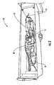
- Figure 1 is a perspective view of a conductor cleaning system according to an embodiment of the invention.
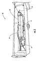
- Figure 2 shows a vibrator housing of the conductor cleaning system of Figure 1 ;
- Figure 3 shows an eccentric weight for use in a vibrator of the conductor cleaning system of Figure 1 ;
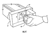
- Figure 4 shows a battery and receptacle for the conductor cleaning system of Figure 1 ;
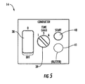
- Figure 5 shows a control panel for the conductor cleaning system of Figure 1 ;
- Figure 6 shows the conductor cleaning system of Figure 1 being carried
- Figure 7 shows the conductor cleaning system of Figure 1 in use
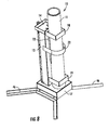
- Figures 8 - 10 show the conductor cleaning system of Figure 1 supported in an upright position by supports;
- Figure 11 shows the conductor cleaning system of Figure 1 fitted with bipods
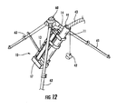
- Figure 12 shows a tri-pod for supporting the conductor cleaning system of Figure 1 ;
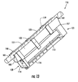
- Figure 13 is a perspective view of a conductor cleaning system according to an embodiment of the invention.
- FIG. 1 an exemplary conductor cleaning system according to the present invention is illustrated in Figure 1 and shown generally at reference numeral 10.
- the system 10 includes a container, such as tube 11 operably connected to a vibrator 12, Figure 2 , contained in a vibrator housing 13, and a control panel 14 for controlling the system 10.
- the container 11 may be disposable or permanently attached to the system 10.
- the vibrator housing 13 is adapted to receive and support the container 11, and includes an attachment rail 16 to allow the system 10 to be attached to a support for easy operation or to allow a user to easily carry the system 10.
- Other attachments such as a hook-type attachment may also be used to attach the system 10 to a bucket of a bucket truck or other suitable support.
- a standing base 17 is disposed at one end of the housing 13 to allow the system 10 to be positioned in a stand-up position such that the tube 11 is in a vertical position.
- the base 17 may be adapted to accept supports to further stabilize the system 10 in the vertical position, as shown in Figures 8-10 .
- Guide straps 18 and 19 are attached to opposing ends 20 and 21 of the housing 13 to provide guides and supports for the tube 11, and a retaining strap 22 is positioned between the guide straps 18 and 19 to lock the tube 11 into position.
- a support 23 is also positioned on a bottom of the housing 13 to further position and lock the tube 11 into position. As shown, the support 23 is V-shaped; however, any suitable geometry may be used to position and lock the tube 11 in position.
- the vibrator housing 13 includes a control system 30 having an electric motor 31, a timer circuit 32, a voltage regulator 33, and the vibrator 12.
- the vibrator 12 includes an eccentric weight 15, like that shown in Figure 3 , to emit vibrations into the tube 11, thereby agitating a cleaning solution contained therein. Together, the motor 31 and vibrator 12 cause the system 10 to vibrate at a specified rate by spinning the eccentric weight 15 at a desired speed. It should be appreciated that the speed of the motor 31 and size of the eccentric weight 15 may be changed to optimize the conductor cleaning efficiency.
- the system 10 is powered by a battery 36.
- the battery 36 is contained in a battery receptacle 37 of the base 17.
- the battery 36 may be replaceable or rechargeable and allows the system 10 to be portable for conductor cleaning both at ground level and at elevated levels.
- the control panel 14 is electrically connected to the control system 30 and includes a power switch 38, a timer 39, a start button 40, and a buzzer 41.
- the power switch 38 turns the system 10 on to a ready state so that the system 10 is ready to clean a conductor.
- the timer 39 allows a user to choose how long the cleaning process is going to last. The amount of time chosen is dependent on the level of contaminants and corrosion products on the surface of the conductor, temperatures, and other factors.
- the start button 40 turns the cleaning process on when depressed, and the buzzer 41 lets a user know when the cleaning process has ended.
- the cleaning solution is contained in the tube 11 to allow an end of a conductor to be cleaned properly while reducing spills and splashes.
- the cleaning solution is designed and optimized to permit cleaning of aluminum strands of conductors without unstranding the conductor. Namely, the cleaning solution is designed to permit internal and external cleaning of aluminum strands of the conductor without reacting and damaging the galvanization of galvanized steel strands; to not react with or degrade aluminum strands after the cleaning process is complete; to clean over a wide range of temperatures; to not react with inhibitor compounds used in compression connector installation; and to be environmentally acceptable.
- the cleaning solution uses a caustic solution of sodium hydroxide (NaOH) as a cleaning agent due to the tri-hydrated oxide of aluminum found in corrosion products being soluble in this type of solution.
- the caustic level of the solution is equal to, or less than, that of standard household cleaners.
- a low concentration of sodium fluoride (NaF) enhances the solubility of the aluminum oxides and reduces the time needed to complete the cleaning.
- the predominant reactions occurring during cleaning are as follows: Al 2 O 3 + 2NaOH ⁇ 2NaAlO 2 +H 2 O 2Al + 2NaOH +2H 2 O ⁇ 2NaAlO 3 + 3H 2 .
- the reaction products are essentially stable and do not react with Al and the corrosion layer Al 2 O 3 .
- the tube 11 is inserted through the guide straps 18 and 19 of the vibrator housing 13 and secured in position by the retaining strap 22 and support 23.
- the tube 11 may be disposable or permanently attached to the system 10.
- the tube 11 may be pre-filled with the cleaning solution and a plug 42 would be inserted into an end of the tube 11 to prevent spilling of the solution.
- the tube would then be attached to the system 10 and carried, as shown in Figure 6 , to the conductor cleaning site. After use, the tube 11 would be removed from the system 10 and the tube and cleaning solution would be properly disposed of.
- the tube 11 In the case of a permanent tube, the tube 11 would be attached to the system 10 and carried to the conductor cleaning site.
- the cleaning solution could be poured into the tube 11 and sealed therein by the plug 42 prior to delivery to the cleaning site, could be delivered to the site in another container and then poured into the tube at the site, or could be in powder form which would be mixed with water at the site.
- a conductor 43 is inserted into the tube 11 so that the cleaning solution contained therein may clean the strands of the conductor 43.
- a baffle 44 may be inserted into the end of the tube 11 to prevent splashing during the cleaning process.
- the system 10 may be supported in various ways to relieve the burden, on the user, of supporting the system 10.
- supports may be attached to the base 17, Figures 8-10 .
- legs 46 are directly attached to the base 17.
- Legs 46 may be secured to the base 17 using fasteners.
- removable legs 47 are secured to the base 17 by pins 48. This allows the legs 47 to be removed when supporting the system 10 in a vertical position is not necessary.
- foldable legs 50 are secured to the base 17 by supports 49 which allow the legs 50 to pivot between a use position and a non-use position about pin 51.
- a bi-pod having legs 53 and 54 may be attached to strap 18. The legs 53 and 54 may be moved between a use position and a non-use position to allow the system 10 to be supported in a non-vertical position.
- a tri-pod 60 may also be used to support the system 10. As shown, the tri-pod 60 includes adjustable legs 61, 62, and 63 to allow for adjustment on uneven surfaces. The system 10 is then hung from the tri-pod 60 using the attachment rail 16.
- system 110 includes a container 111 operably connected to a vibrator contained in a vibrator housing 113, a control panel 114, an attachment rail 116, a base 117, and retaining straps 118, 119, and 122.
- the container 111 of system 110 is a trough-like container to allow cleaning of a conductor 143 at a point intermediary of opposing ends of the conductor 143 without cutting. This allows the conductor 143 to be cleaned at locations where compression fittings, such as repair sleeves and T-connections, are being installed along the conductor 143.
- the container 111 In use, the container 111 is positioned at a point along the conductor 143 where cleaning is desired and moved into engagement with the conductor 143. Seals 160 and 161 permit the conductor 143 to be pressed into the container 111 until the conductor 143 is immersed in the cleaning solution. The seals 160 and 161 prevent the cleaning solution from leaking between the container 111 and the conductor 143.
Landscapes
- Cleaning By Liquid Or Steam (AREA)
- Cleaning In General (AREA)
- Cleaning And De-Greasing Of Metallic Materials By Chemical Methods (AREA)
Abstract
Description
- The present invention relates generally to a conductor cleaning system, and more particularly to a system for cleaning aluminum strands of all aluminum and steel reinforced conductors, such as ACSS, ACSR, ACAR, and AAA.
- In current power transmission systems, failures can pose a significant risk to the reliability of the system. There are several factors that contribute to these failures - one such factor is the failure of compression connectors.
- Current data suggests that a primary root cause for failures in compression connectors is improper installation. Examples of improper installation include lack of compound, alignment, wrong die, and poor cleaning of the aluminum strands of the conductor prior to installation of compression connectors. Research indicates that corrosion products and other contaminants (resulting from years of exposure to the environment) left on the conductors during splice assembly can raise the resistance of the splice-conductor joint. Cyclical variations of load current feeding through the increased resistance of the splice-conductor joint causes thermal expansion/contraction that eventually reduces the grip of the splice to a point where it can no longer hold the conductor.
- Currently, compression connector installers clean the aluminum strands with a wire brush, which results in ineffective cleaning of the strands, leaving corrosion products and other contaminants behind. Further, the installer cannot clean internal strands using the wire brush unless the installer takes the time to unstrand the conductor. Unfortunately, unstranding is impractical in most field conditions and can increase the risk of damage to the individual strands.
-
DE 32 40 467 -
US 3 291 458 discloses a vibratory article washer. -
GB 548 960 - Accordingly, there is a need for a conductor cleaning system that can effectively clean both outer and inner strands of a conductor without the need to unstrand the conductor.
- These and other shortcomings of the prior art are addressed by the present invention, which provides a conductor cleaning system capable of cleaning external and internal strands of a conductor without unstranding the conductor.
- According to one aspect of the present invention, a conductor cleaning system, comprising: (a) a container adapted to contain a cleaning solution and receive a portion of a conductor to be cleaned; (b) a housing adapted to receive and support the container; and (c)a control system contained in the housing, the control system having a motor and a vibrator to impart vibrations into the container such that the cleaning solution is agitated; characterised in that: the system further includes a baffle positioned in an end of the container such that a conductor is inserted therethrough into the container for cleaning, the baffle being adapted to prevent splashes during a cleaning cycle.
- Further features of the present invention are set out in the appended claims.
- The subject matter that is regarded as the invention may be best understood by reference to the following description taken in conjunction with the accompanying drawing figures in which:
-
Figure 1 is a perspective view of a conductor cleaning system according to an embodiment of the invention; -
Figure 2 shows a vibrator housing of the conductor cleaning system ofFigure 1 ; -
Figure 3 shows an eccentric weight for use in a vibrator of the conductor cleaning system ofFigure 1 ; -
Figure 4 shows a battery and receptacle for the conductor cleaning system ofFigure 1 ; -
Figure 5 shows a control panel for the conductor cleaning system ofFigure 1 ; -
Figure 6 shows the conductor cleaning system ofFigure 1 being carried; -
Figure 7 shows the conductor cleaning system ofFigure 1 in use; -
Figures 8 - 10 show the conductor cleaning system ofFigure 1 supported in an upright position by supports; -
Figure 11 shows the conductor cleaning system ofFigure 1 fitted with bipods; -
Figure 12 shows a tri-pod for supporting the conductor cleaning system ofFigure 1 ; and -
Figure 13 is a perspective view of a conductor cleaning system according to an embodiment of the invention. - Referring to the drawings, an exemplary conductor cleaning system according to the present invention is illustrated in
Figure 1 and shown generally atreference numeral 10. Thesystem 10 includes a container, such astube 11 operably connected to avibrator 12,Figure 2 , contained in avibrator housing 13, and acontrol panel 14 for controlling thesystem 10. Thecontainer 11 may be disposable or permanently attached to thesystem 10. - The
vibrator housing 13 is adapted to receive and support thecontainer 11, and includes anattachment rail 16 to allow thesystem 10 to be attached to a support for easy operation or to allow a user to easily carry thesystem 10. Other attachments such as a hook-type attachment may also be used to attach thesystem 10 to a bucket of a bucket truck or other suitable support. A standingbase 17 is disposed at one end of thehousing 13 to allow thesystem 10 to be positioned in a stand-up position such that thetube 11 is in a vertical position. Thebase 17 may be adapted to accept supports to further stabilize thesystem 10 in the vertical position, as shown inFigures 8-10 .Guide straps opposing ends housing 13 to provide guides and supports for thetube 11, and aretaining strap 22 is positioned between theguide straps tube 11 into position. Asupport 23 is also positioned on a bottom of thehousing 13 to further position and lock thetube 11 into position. As shown, thesupport 23 is V-shaped; however, any suitable geometry may be used to position and lock thetube 11 in position. - As shown in
Figure 2 , thevibrator housing 13 includes acontrol system 30 having anelectric motor 31, atimer circuit 32, avoltage regulator 33, and thevibrator 12. Thevibrator 12 includes aneccentric weight 15, like that shown inFigure 3 , to emit vibrations into thetube 11, thereby agitating a cleaning solution contained therein. Together, themotor 31 andvibrator 12 cause thesystem 10 to vibrate at a specified rate by spinning theeccentric weight 15 at a desired speed. It should be appreciated that the speed of themotor 31 and size of theeccentric weight 15 may be changed to optimize the conductor cleaning efficiency. - Referring to
Figure 4 , thesystem 10 is powered by abattery 36. Thebattery 36 is contained in abattery receptacle 37 of thebase 17. Thebattery 36 may be replaceable or rechargeable and allows thesystem 10 to be portable for conductor cleaning both at ground level and at elevated levels. - As illustrated in
Figure 5 , thecontrol panel 14 is electrically connected to thecontrol system 30 and includes apower switch 38, atimer 39, astart button 40, and abuzzer 41. Thepower switch 38 turns thesystem 10 on to a ready state so that thesystem 10 is ready to clean a conductor. Thetimer 39 allows a user to choose how long the cleaning process is going to last. The amount of time chosen is dependent on the level of contaminants and corrosion products on the surface of the conductor, temperatures, and other factors. Thestart button 40 turns the cleaning process on when depressed, and thebuzzer 41 lets a user know when the cleaning process has ended. - The cleaning solution is contained in the
tube 11 to allow an end of a conductor to be cleaned properly while reducing spills and splashes. The cleaning solution is designed and optimized to permit cleaning of aluminum strands of conductors without unstranding the conductor. Namely, the cleaning solution is designed to permit internal and external cleaning of aluminum strands of the conductor without reacting and damaging the galvanization of galvanized steel strands; to not react with or degrade aluminum strands after the cleaning process is complete; to clean over a wide range of temperatures; to not react with inhibitor compounds used in compression connector installation; and to be environmentally acceptable. - The cleaning solution uses a caustic solution of sodium hydroxide (NaOH) as a cleaning agent due to the tri-hydrated oxide of aluminum found in corrosion products being soluble in this type of solution. The caustic level of the solution is equal to, or less than, that of standard household cleaners. A low concentration of sodium fluoride (NaF) enhances the solubility of the aluminum oxides and reduces the time needed to complete the cleaning. The predominant reactions occurring during cleaning are as follows:
Al2O3 + 2NaOH ⇔ 2NaAlO2 +H2O
2Al + 2NaOH +2H2O → 2NaAlO3 + 3H2.
The reaction products are essentially stable and do not react with Al and the corrosion layer Al2O3. Only NaOH chemically attacks both Al and Al2O3. Examples of cleaning solutions are shown in the Table below.Solution Caustic Level No. Composition 1 NaOH + H2O High 2 NaOH + NaPO4•2H2O + NaF + H2O Medium 3 NaOH + NaPOa•12H2O + NaF + H2O Medium-Low 4 NaOH + NaF + H2O Low - In testing, all of the above solutions provided good to excellent cleaning results. For example, in one test, a cleaning solution having a low level of causticity and relatively simple composition was chosen. The cleaning solution had the following concentrations:
- Sodium Hydroxide (NaOH) = 20g
- Sodium Fluoride (NaF) = 15g
- Water (H2O) = 1L.
- In use, the
tube 11 is inserted through the guide straps 18 and 19 of thevibrator housing 13 and secured in position by the retainingstrap 22 andsupport 23. As discussed, thetube 11 may be disposable or permanently attached to thesystem 10. In the case of a disposable tube, thetube 11 may be pre-filled with the cleaning solution and aplug 42 would be inserted into an end of thetube 11 to prevent spilling of the solution. The tube would then be attached to thesystem 10 and carried, as shown inFigure 6 , to the conductor cleaning site. After use, thetube 11 would be removed from thesystem 10 and the tube and cleaning solution would be properly disposed of. - In the case of a permanent tube, the
tube 11 would be attached to thesystem 10 and carried to the conductor cleaning site. The cleaning solution could be poured into thetube 11 and sealed therein by theplug 42 prior to delivery to the cleaning site, could be delivered to the site in another container and then poured into the tube at the site, or could be in powder form which would be mixed with water at the site. - Referring to
Figure 7 , once at the conductor cleaning site, aconductor 43 is inserted into thetube 11 so that the cleaning solution contained therein may clean the strands of theconductor 43. Abaffle 44 may be inserted into the end of thetube 11 to prevent splashing during the cleaning process. With theconductor 43 positioned in the cleaning solution, thepower switch 38 is moved to the on position and thetimer 39 is moved to a desired time limit. The duration of vibration is determined by the user depending on the present temperature and the amount of deposits on the conductor surfaces. Thestart button 40 is then depressed and the motor rotates theeccentric weight 15 of thevibrator 12, thereby causing vibrations to agitate the cleaning solution to ensure that internal and external strands of the conductor are cleaned. - As discussed, during the cleaning cycle of the conductor, the
system 10 may be supported in various ways to relieve the burden, on the user, of supporting thesystem 10. For example, if the system is to be supported in a vertical position, supports may be attached to thebase 17,Figures 8-10 . As shown inFigure 8 ,legs 46 are directly attached to thebase 17.Legs 46 may be secured to the base 17 using fasteners. As illustrated inFigure 9 ,removable legs 47 are secured to thebase 17 bypins 48. This allows thelegs 47 to be removed when supporting thesystem 10 in a vertical position is not necessary. As shown inFigure 10 ,foldable legs 50 are secured to thebase 17 bysupports 49 which allow thelegs 50 to pivot between a use position and a non-use position aboutpin 51. - Other support methods may also be employed. For example, in
Figure 11 , abi-pod having legs strap 18. Thelegs system 10 to be supported in a non-vertical position. As shown inFigure 12 , a tri-pod 60 may also be used to support thesystem 10. As shown, the tri-pod 60 includesadjustable legs system 10 is then hung from the tri-pod 60 using theattachment rail 16. - Referring to
Figure 13 , aconductor cleaning system 110 is shown. Likesystem 10,system 110 includes acontainer 111 operably connected to a vibrator contained in avibrator housing 113, acontrol panel 114, anattachment rail 116, abase 117, and retainingstraps system 10, thecontainer 111 ofsystem 110 is a trough-like container to allow cleaning of aconductor 143 at a point intermediary of opposing ends of theconductor 143 without cutting. This allows theconductor 143 to be cleaned at locations where compression fittings, such as repair sleeves and T-connections, are being installed along theconductor 143. - In use, the
container 111 is positioned at a point along theconductor 143 where cleaning is desired and moved into engagement with theconductor 143.Seals conductor 143 to be pressed into thecontainer 111 until theconductor 143 is immersed in the cleaning solution. Theseals container 111 and theconductor 143. - The foregoing has described a conductor cleaning system. While specific embodiments of the present invention have been described, it will be apparent to those skilled in the art that various modifications thereto can be made without departing from the scope of the invention. Accordingly, the foregoing description of the preferred embodiment of the invention and the best mode for practicing the invention are provided for the purpose of illustration only and not for the purpose of limitation.
| Cleaning Effectiveness Rated 0 to 5 with 5 Being the Best | ||||||
| With Agitation | Without Agitation | |||||
| Temperature (C) | 1 Min | 2.5 Min | 5 Min | 1 Min | 2.5 Min | 5 |
| 0 | 3 | 4 | 4 | 1 | 1 | 2 |
| 25 | 4 | 5 | 5 | 2 | 3 | 5 |
| 50 | 5 | 5 | 5 | 5 | 5 | 5 |
| 70 | 5 | 5 | 5 | 5 | 5 | 5 |
Claims (9)
- A conductor cleaning system (10, 110), comprising:(a) a container (11, 111) adapted to contain a cleaning solution and receive a portion of a conductor (43, 143) to be cleaned;(b) a housing (13, 113) adapted to receive and support the container (11, 111); and(c) a control system (30) contained in the housing (13, 113), the control system (30) having a motor (31) and a vibrator (12) to impart vibrations into the container (11, 111) such that the cleaning solution is agitated;characterised in that:the system further includes a baffle (44) positioned in an end of the container (11, 111) such that a conductor (43, 143) is inserted therethrough into the container (11, 111) for cleaning, the baffle (44) being adapted to prevent splashes during a cleaning cycle.
- The conductor cleaning system (10, 110) according to claim 1, further including a control panel (14) electrically connected to the control system (30) and adapted to control the conductor cleaning system (10, 110).
- The conductor cleaning system (10, 110) according to claim 2, wherein the control panel (14) includes a power switch (38), a timer (39), and a start button (40).
- The conductor cleaning system (10, 110) according to claim 1, wherein the control system (30) further includes a voltage regulator (33) and a timer circuit (32).
- The conductor cleaning system (10, 110) according to claim 1, wherein the vibrator (12) includes an eccentric weight (15) adapted to be spun by the motor (31) at a specified rate.
- The conductor cleaning system (10, 110) according to claim 1, wherein the housing (13, 113) includes an attachment rail (16, 116) adapted to allow the conductor cleaning system (10, 110) to be attached to a support or carried by a user.
- The conductor cleaning system (10, 110) according to claim 1, wherein the container (111) is a trough and trough includes seals (160, 161) disposed at opposing ends of the trough to prevent the cleaning solution from leaking between the conductor (143) being cleaned and the trough.
- The conductor cleaning system (10, 110) according to claim 1, further including a plug (42) adapted to be inserted into an end of the container (11, 111) to prevent the cleaning solution from exiting the container (11, 111) during transport of the conductor cleaning system (10, 110).
- The conductor cleaning system (10, 110) according to claim 1, wherein the cleaning solution is a caustic solution containing NaOH.
Applications Claiming Priority (1)
| Application Number | Priority Date | Filing Date | Title |
|---|---|---|---|
| US12/357,610 US8839804B2 (en) | 2009-01-22 | 2009-01-22 | Conductor cleaning system |
Publications (2)
| Publication Number | Publication Date |
|---|---|
| EP2210676A1 EP2210676A1 (en) | 2010-07-28 |
| EP2210676B1 true EP2210676B1 (en) | 2011-06-22 |
Family
ID=42110267
Family Applications (1)
| Application Number | Title | Priority Date | Filing Date |
|---|---|---|---|
| EP10151244A Active EP2210676B1 (en) | 2009-01-22 | 2010-01-20 | Conductor cleaning system |
Country Status (6)
| Country | Link |
|---|---|
| US (1) | US8839804B2 (en) |
| EP (1) | EP2210676B1 (en) |
| AT (1) | ATE513630T1 (en) |
| AU (1) | AU2010200196B2 (en) |
| CA (1) | CA2690136C (en) |
| ES (1) | ES2367606T3 (en) |
Families Citing this family (3)
| Publication number | Priority date | Publication date | Assignee | Title |
|---|---|---|---|---|
| CN108262304B (en) * | 2016-12-30 | 2024-02-02 | 中核建中核燃料元件有限公司 | Throw material container ultrasonic cleaning basket |
| US11192148B2 (en) * | 2019-09-30 | 2021-12-07 | Utility Solutions, Inc. | Conductor cleaning apparatus |
| CN112264386A (en) * | 2020-09-24 | 2021-01-26 | 郑州竹蜻蜓电子科技有限公司 | Damage-proof type belt cleaning device that ceramic capacitor made |
Family Cites Families (44)
| Publication number | Priority date | Publication date | Assignee | Title |
|---|---|---|---|---|
| US1428528A (en) * | 1921-03-05 | 1922-09-12 | Bryan George | Scrubbing pail |
| US1979241A (en) * | 1933-06-14 | 1934-11-06 | Harry M Albanese | Paintbrush preserver |
| GB548960A (en) | 1941-07-17 | 1942-10-30 | Alexander Howard Tod | Improved method of degreasing or cleaning articles |
| US2650872A (en) * | 1947-10-30 | 1953-09-01 | Lever Brothers Ltd | Method and apparatus utilizing compressional wave energy in the upper sonic and supersonic range for washing textiles |
| US2828231A (en) * | 1954-03-31 | 1958-03-25 | Gen Electric | Method and apparatus for ultrasonic cleansing |
| US2802476A (en) * | 1954-06-10 | 1957-08-13 | Detrex Corp | Cleaning apparatus |
| US3043724A (en) * | 1958-04-24 | 1962-07-10 | Dishmaster Appliances Ltd | Method of washing glasses or the like |
| US3291640A (en) | 1963-05-27 | 1966-12-13 | Chemclean Corp | Ultrasonic cleaning process |
| US3291458A (en) | 1965-02-24 | 1966-12-13 | Hedot Company | Vibratory article washer |
| US3481687A (en) * | 1965-03-08 | 1969-12-02 | Sherman S Fishman | Method and apparatus for ultrasonic sterilization |
| US3525243A (en) * | 1967-06-15 | 1970-08-25 | Gulton Ind Inc | Wire cleaning apparatus |
| US3526458A (en) * | 1968-06-24 | 1970-09-01 | Taffet Electronics Inc | Microfilm reader-printer |
| US3688785A (en) * | 1970-12-02 | 1972-09-05 | Jackson B Stevens | Paint roller cleaner |
| US3698408A (en) * | 1971-06-11 | 1972-10-17 | Branson Instr | Ultrasonic processing apparatus |
| DE2145664A1 (en) | 1971-09-13 | 1973-03-22 | Kabel Metallwerke Ghh | USE OF DEEP-FREEZING MEDIA TO REMOVE MATERIALS FROM METAL SURFACES |
| US3937236A (en) * | 1974-10-07 | 1976-02-10 | Mdt Chemical Company | Ultrasonic cleaning device |
| JPS5512620A (en) * | 1978-07-11 | 1980-01-29 | Sumitomo Electric Industries | Methdo of manufacturing insulated wire |
| US4272300A (en) | 1978-08-11 | 1981-06-09 | Reliable Electric Company | Method for cleaning grease-filled cable stub |
| US4167341A (en) * | 1978-10-06 | 1979-09-11 | Doyel John S | Vibratory action cleaning device |
| FR2478356A1 (en) * | 1980-02-18 | 1981-09-18 | Goulet Michel | Ultrasonic record player stylus cleaner - has piezoelectric cell attached to cylindrical container coaxial with cylinder mounted on turntable |
| US4326316A (en) | 1980-10-06 | 1982-04-27 | Dolenti Alfred N | Hot stick rotary brush for cleaning aerial conductors |
| US4503577A (en) * | 1982-06-14 | 1985-03-12 | Quadrex Hps, Inc. | Pipe and hose decontamination apparatus |
| DE3240467A1 (en) | 1982-11-02 | 1984-05-03 | Werner 8272 Triboltingen Rietmann | Operating method for degreasing the cores of a core bundle of an electrical cable, and a device for carrying out the method |
| FR2543459B1 (en) * | 1983-04-01 | 1986-07-11 | Annemasse Ultrasons | METHOD FOR CLEANING IN A SOLVENT MEDIUM OF AT LEAST ONE CONTINUOUS LONGILINE OBJECT, APPARATUS FOR IMPLEMENTING THE METHOD AND USE OF SAID APPARATUS |
| JPS60242881A (en) * | 1984-05-17 | 1985-12-02 | 金沢 政男 | Ultrasonic wave washing machine |
| US4763677A (en) * | 1986-11-26 | 1988-08-16 | Techalloy Illinois, Inc. | Sonic treatment apparatus |
| US4991609A (en) * | 1988-05-16 | 1991-02-12 | Iben Browning | Ultrasonic cleaning method and apparatus |
| DE4009721A1 (en) * | 1990-03-27 | 1991-10-02 | Werner Meissner | Ultrasonic cleaning of wire - has chamber through which wire is pulled and filled with ultrasonic fluid and transducer |
| US5076305A (en) * | 1990-08-13 | 1991-12-31 | Kevin T. Williams | Apparatus for cleaning by rapid vibration |
| US5319823A (en) | 1992-10-20 | 1994-06-14 | Hastings Fiber Glass Products, Inc. | Conductor cleaning brush with manually graspable handle adapted for mounting on shotgun stick |
| JPH0819544B2 (en) * | 1993-02-05 | 1996-02-28 | 協和電線株式会社 | Lead steel wire for electronic parts and manufacturing method thereof |
| US5409594A (en) * | 1993-11-23 | 1995-04-25 | Dynamotive Corporation | Ultrasonic agitator |
| TW275594B (en) * | 1994-11-14 | 1996-05-11 | Yoshino Denki Kk | Ultrasonic cleaning device |
| US5571336A (en) | 1995-09-29 | 1996-11-05 | Wurzburger; Stephen R. | Base solution for cleaning aluminum |
| US5711327A (en) * | 1995-10-10 | 1998-01-27 | Fields; John T. | System for vibration cleaning of articles including radiators |
| DE10153701C1 (en) * | 2001-10-31 | 2003-05-15 | Hielscher Systems Gmbh | Arrangement for cleaning products with a substantially circular cross-section such as wires, profiles, pipes |
| US6719850B2 (en) * | 2002-01-11 | 2004-04-13 | Connoisseurs Products Corp. | Sonic jewelry cleaner |
| US6695164B1 (en) * | 2002-02-20 | 2004-02-24 | Steven A. Chayer | Storage systems and methods for paint roller sleeves |
| US7107596B2 (en) * | 2002-03-14 | 2006-09-12 | International Business Machines Corporation | Statistically-triggered heuristics |
| US7451772B2 (en) * | 2005-08-01 | 2008-11-18 | Gilwil Llc | Ultrasonic cleaning method and apparatus |
| US7647665B2 (en) * | 2005-10-31 | 2010-01-19 | General Electric Company | Apparatus and method for cleaning control rod drive mechanism |
| DE102006062705B4 (en) * | 2006-03-30 | 2015-07-30 | Krohne Ag | ultrasonic flowmeter |
| KR20090022856A (en) * | 2007-08-31 | 2009-03-04 | 엘지전자 주식회사 | dish washer |
| US7748524B2 (en) * | 2007-12-03 | 2010-07-06 | Edward Ruzumna | Paint brush cleaner and method |
-
2009
- 2009-01-22 US US12/357,610 patent/US8839804B2/en active Active
-
2010
- 2010-01-12 CA CA2690136A patent/CA2690136C/en active Active
- 2010-01-18 AU AU2010200196A patent/AU2010200196B2/en active Active
- 2010-01-20 AT AT10151244T patent/ATE513630T1/en not_active IP Right Cessation
- 2010-01-20 EP EP10151244A patent/EP2210676B1/en active Active
- 2010-01-20 ES ES10151244T patent/ES2367606T3/en active Active
Also Published As
| Publication number | Publication date |
|---|---|
| AU2010200196A1 (en) | 2010-08-05 |
| ATE513630T1 (en) | 2011-07-15 |
| US8839804B2 (en) | 2014-09-23 |
| AU2010200196B2 (en) | 2011-10-20 |
| EP2210676A1 (en) | 2010-07-28 |
| CA2690136C (en) | 2013-11-26 |
| ES2367606T3 (en) | 2011-11-04 |
| CA2690136A1 (en) | 2010-07-22 |
| US20100180921A1 (en) | 2010-07-22 |
Similar Documents
| Publication | Publication Date | Title |
|---|---|---|
| AU2010200196B2 (en) | Conductor cleaning system | |
| CN209947804U (en) | Wafer cleaning device | |
| CN206897966U (en) | A kind of glass display screen ultrasonic cleaner | |
| CN103184463B (en) | Acid dipping device used for nuclear rod jacketing tube and having function of preventing acid wash from leaking | |
| AU2010200197B2 (en) | Conductor cleaning system and method | |
| CN212613865U (en) | Building engineering pre-buried exposed steel bar rust prevention device | |
| JP3227391B2 (en) | Cleaning equipment for synthetic resin molds | |
| CN213287878U (en) | Recovery unit for waste machine parts | |
| CN213495637U (en) | A kind of repairing agent spraying device with convenient adjustment for soil remediation | |
| CN213670834U (en) | A cleaning device and chemical forming device for cleaning current probe in place | |
| CN210214474U (en) | Integral type elevator guide rail belt cleaning device | |
| CN219823626U (en) | Potassium chloride oral liquid filling equipment | |
| GB2176382A (en) | Watering device | |
| CN211587632U (en) | Cleaning device for monocrystalline copper bonding gold wire | |
| CN221467666U (en) | High support photovoltaic module cleaning device | |
| CN210595225U (en) | Filling machine | |
| CN214182876U (en) | Mixing device for producing polyaluminium chloride | |
| KR100320551B1 (en) | Electrolytic polishing | |
| CN217069885U (en) | Oil stain cleaning device for maintenance of oil field mechanical equipment | |
| CN212167305U (en) | Lubricating oil production is with mixing cauldron raw materials filling device | |
| CN213593292U (en) | Cutting device is used in road and bridge construction | |
| CN224147955U (en) | Anti-dazzle frosting liquid processing tank | |
| CN214751553U (en) | Stirring reactor under low-temperature constant-temperature environment | |
| CN216458277U (en) | Discharge structure for PVC stabilizer stirring device | |
| CN217887876U (en) | Resin waste water processing apparatus |
Legal Events
| Date | Code | Title | Description |
|---|---|---|---|
| PUAI | Public reference made under article 153(3) epc to a published international application that has entered the european phase |
Free format text: ORIGINAL CODE: 0009012 |
|
| 17P | Request for examination filed |
Effective date: 20100120 |
|
| AK | Designated contracting states |
Kind code of ref document: A1 Designated state(s): AT BE BG CH CY CZ DE DK EE ES FI FR GB GR HR HU IE IS IT LI LT LU LV MC MK MT NL NO PL PT RO SE SI SK SM TR |
|
| GRAP | Despatch of communication of intention to grant a patent |
Free format text: ORIGINAL CODE: EPIDOSNIGR1 |
|
| GRAC | Information related to communication of intention to grant a patent modified |
Free format text: ORIGINAL CODE: EPIDOSCIGR1 |
|
| RIC1 | Information provided on ipc code assigned before grant |
Ipc: B08B 3/10 20060101ALI20110121BHEP Ipc: B08B 3/04 20060101AFI20110121BHEP |
|
| GRAC | Information related to communication of intention to grant a patent modified |
Free format text: ORIGINAL CODE: EPIDOSCIGR1 |
|
| GRAS | Grant fee paid |
Free format text: ORIGINAL CODE: EPIDOSNIGR3 |
|
| GRAA | (expected) grant |
Free format text: ORIGINAL CODE: 0009210 |
|
| AK | Designated contracting states |
Kind code of ref document: B1 Designated state(s): AT BE BG CH CY CZ DE DK EE ES FI FR GB GR HR HU IE IS IT LI LT LU LV MC MK MT NL NO PL PT RO SE SI SK SM TR |
|
| REG | Reference to a national code |
Ref country code: GB Ref legal event code: FG4D |
|
| REG | Reference to a national code |
Ref country code: CH Ref legal event code: EP |
|
| REG | Reference to a national code |
Ref country code: IE Ref legal event code: FG4D |
|
| REG | Reference to a national code |
Ref country code: DE Ref legal event code: R096 Ref document number: 602010000070 Country of ref document: DE Effective date: 20110728 |
|
| REG | Reference to a national code |
Ref country code: NL Ref legal event code: VDEP Effective date: 20110622 |
|
| PG25 | Lapsed in a contracting state [announced via postgrant information from national office to epo] |
Ref country code: LT Free format text: LAPSE BECAUSE OF FAILURE TO SUBMIT A TRANSLATION OF THE DESCRIPTION OR TO PAY THE FEE WITHIN THE PRESCRIBED TIME-LIMIT Effective date: 20110622 Ref country code: SE Free format text: LAPSE BECAUSE OF FAILURE TO SUBMIT A TRANSLATION OF THE DESCRIPTION OR TO PAY THE FEE WITHIN THE PRESCRIBED TIME-LIMIT Effective date: 20110622 Ref country code: HR Free format text: LAPSE BECAUSE OF FAILURE TO SUBMIT A TRANSLATION OF THE DESCRIPTION OR TO PAY THE FEE WITHIN THE PRESCRIBED TIME-LIMIT Effective date: 20110622 Ref country code: NO Free format text: LAPSE BECAUSE OF FAILURE TO SUBMIT A TRANSLATION OF THE DESCRIPTION OR TO PAY THE FEE WITHIN THE PRESCRIBED TIME-LIMIT Effective date: 20110922 |
|
| REG | Reference to a national code |
Ref country code: ES Ref legal event code: FG2A Ref document number: 2367606 Country of ref document: ES Kind code of ref document: T3 Effective date: 20111104 |
|
| PG25 | Lapsed in a contracting state [announced via postgrant information from national office to epo] |
Ref country code: LV Free format text: LAPSE BECAUSE OF FAILURE TO SUBMIT A TRANSLATION OF THE DESCRIPTION OR TO PAY THE FEE WITHIN THE PRESCRIBED TIME-LIMIT Effective date: 20110622 Ref country code: CY Free format text: LAPSE BECAUSE OF FAILURE TO SUBMIT A TRANSLATION OF THE DESCRIPTION OR TO PAY THE FEE WITHIN THE PRESCRIBED TIME-LIMIT Effective date: 20110622 Ref country code: AT Free format text: LAPSE BECAUSE OF FAILURE TO SUBMIT A TRANSLATION OF THE DESCRIPTION OR TO PAY THE FEE WITHIN THE PRESCRIBED TIME-LIMIT Effective date: 20110622 Ref country code: FI Free format text: LAPSE BECAUSE OF FAILURE TO SUBMIT A TRANSLATION OF THE DESCRIPTION OR TO PAY THE FEE WITHIN THE PRESCRIBED TIME-LIMIT Effective date: 20110622 Ref country code: SI Free format text: LAPSE BECAUSE OF FAILURE TO SUBMIT A TRANSLATION OF THE DESCRIPTION OR TO PAY THE FEE WITHIN THE PRESCRIBED TIME-LIMIT Effective date: 20110622 Ref country code: GR Free format text: LAPSE BECAUSE OF FAILURE TO SUBMIT A TRANSLATION OF THE DESCRIPTION OR TO PAY THE FEE WITHIN THE PRESCRIBED TIME-LIMIT Effective date: 20110923 |
|
| PG25 | Lapsed in a contracting state [announced via postgrant information from national office to epo] |
Ref country code: BE Free format text: LAPSE BECAUSE OF FAILURE TO SUBMIT A TRANSLATION OF THE DESCRIPTION OR TO PAY THE FEE WITHIN THE PRESCRIBED TIME-LIMIT Effective date: 20110622 Ref country code: NL Free format text: LAPSE BECAUSE OF FAILURE TO SUBMIT A TRANSLATION OF THE DESCRIPTION OR TO PAY THE FEE WITHIN THE PRESCRIBED TIME-LIMIT Effective date: 20110622 |
|
| PG25 | Lapsed in a contracting state [announced via postgrant information from national office to epo] |
Ref country code: CZ Free format text: LAPSE BECAUSE OF FAILURE TO SUBMIT A TRANSLATION OF THE DESCRIPTION OR TO PAY THE FEE WITHIN THE PRESCRIBED TIME-LIMIT Effective date: 20110622 Ref country code: IS Free format text: LAPSE BECAUSE OF FAILURE TO SUBMIT A TRANSLATION OF THE DESCRIPTION OR TO PAY THE FEE WITHIN THE PRESCRIBED TIME-LIMIT Effective date: 20111022 Ref country code: PT Free format text: LAPSE BECAUSE OF FAILURE TO SUBMIT A TRANSLATION OF THE DESCRIPTION OR TO PAY THE FEE WITHIN THE PRESCRIBED TIME-LIMIT Effective date: 20111024 Ref country code: EE Free format text: LAPSE BECAUSE OF FAILURE TO SUBMIT A TRANSLATION OF THE DESCRIPTION OR TO PAY THE FEE WITHIN THE PRESCRIBED TIME-LIMIT Effective date: 20110622 |
|
| PG25 | Lapsed in a contracting state [announced via postgrant information from national office to epo] |
Ref country code: PL Free format text: LAPSE BECAUSE OF FAILURE TO SUBMIT A TRANSLATION OF THE DESCRIPTION OR TO PAY THE FEE WITHIN THE PRESCRIBED TIME-LIMIT Effective date: 20110622 Ref country code: SK Free format text: LAPSE BECAUSE OF FAILURE TO SUBMIT A TRANSLATION OF THE DESCRIPTION OR TO PAY THE FEE WITHIN THE PRESCRIBED TIME-LIMIT Effective date: 20110622 |
|
| PLBE | No opposition filed within time limit |
Free format text: ORIGINAL CODE: 0009261 |
|
| STAA | Information on the status of an ep patent application or granted ep patent |
Free format text: STATUS: NO OPPOSITION FILED WITHIN TIME LIMIT |
|
| 26N | No opposition filed |
Effective date: 20120323 |
|
| PG25 | Lapsed in a contracting state [announced via postgrant information from national office to epo] |
Ref country code: IT Free format text: LAPSE BECAUSE OF FAILURE TO SUBMIT A TRANSLATION OF THE DESCRIPTION OR TO PAY THE FEE WITHIN THE PRESCRIBED TIME-LIMIT Effective date: 20110622 |
|
| PG25 | Lapsed in a contracting state [announced via postgrant information from national office to epo] |
Ref country code: DK Free format text: LAPSE BECAUSE OF FAILURE TO SUBMIT A TRANSLATION OF THE DESCRIPTION OR TO PAY THE FEE WITHIN THE PRESCRIBED TIME-LIMIT Effective date: 20110622 |
|
| REG | Reference to a national code |
Ref country code: DE Ref legal event code: R097 Ref document number: 602010000070 Country of ref document: DE Effective date: 20120323 |
|
| PG25 | Lapsed in a contracting state [announced via postgrant information from national office to epo] |
Ref country code: MC Free format text: LAPSE BECAUSE OF NON-PAYMENT OF DUE FEES Effective date: 20120131 |
|
| REG | Reference to a national code |
Ref country code: IE Ref legal event code: MM4A |
|
| PG25 | Lapsed in a contracting state [announced via postgrant information from national office to epo] |
Ref country code: IE Free format text: LAPSE BECAUSE OF NON-PAYMENT OF DUE FEES Effective date: 20120120 |
|
| PG25 | Lapsed in a contracting state [announced via postgrant information from national office to epo] |
Ref country code: MK Free format text: LAPSE BECAUSE OF FAILURE TO SUBMIT A TRANSLATION OF THE DESCRIPTION OR TO PAY THE FEE WITHIN THE PRESCRIBED TIME-LIMIT Effective date: 20110622 |
|
| PG25 | Lapsed in a contracting state [announced via postgrant information from national office to epo] |
Ref country code: BG Free format text: LAPSE BECAUSE OF FAILURE TO SUBMIT A TRANSLATION OF THE DESCRIPTION OR TO PAY THE FEE WITHIN THE PRESCRIBED TIME-LIMIT Effective date: 20110922 |
|
| PG25 | Lapsed in a contracting state [announced via postgrant information from national office to epo] |
Ref country code: MT Free format text: LAPSE BECAUSE OF FAILURE TO SUBMIT A TRANSLATION OF THE DESCRIPTION OR TO PAY THE FEE WITHIN THE PRESCRIBED TIME-LIMIT Effective date: 20110622 |
|
| PG25 | Lapsed in a contracting state [announced via postgrant information from national office to epo] |
Ref country code: TR Free format text: LAPSE BECAUSE OF FAILURE TO SUBMIT A TRANSLATION OF THE DESCRIPTION OR TO PAY THE FEE WITHIN THE PRESCRIBED TIME-LIMIT Effective date: 20110622 |
|
| PGFP | Annual fee paid to national office [announced via postgrant information from national office to epo] |
Ref country code: DE Payment date: 20140129 Year of fee payment: 5 |
|
| PG25 | Lapsed in a contracting state [announced via postgrant information from national office to epo] |
Ref country code: LU Free format text: LAPSE BECAUSE OF NON-PAYMENT OF DUE FEES Effective date: 20120120 Ref country code: SM Free format text: LAPSE BECAUSE OF FAILURE TO SUBMIT A TRANSLATION OF THE DESCRIPTION OR TO PAY THE FEE WITHIN THE PRESCRIBED TIME-LIMIT Effective date: 20110622 |
|
| PGFP | Annual fee paid to national office [announced via postgrant information from national office to epo] |
Ref country code: ES Payment date: 20140127 Year of fee payment: 5 |
|
| PG25 | Lapsed in a contracting state [announced via postgrant information from national office to epo] |
Ref country code: HU Free format text: LAPSE BECAUSE OF FAILURE TO SUBMIT A TRANSLATION OF THE DESCRIPTION OR TO PAY THE FEE WITHIN THE PRESCRIBED TIME-LIMIT Effective date: 20100120 |
|
| REG | Reference to a national code |
Ref country code: CH Ref legal event code: PL |
|
| PG25 | Lapsed in a contracting state [announced via postgrant information from national office to epo] |
Ref country code: CH Free format text: LAPSE BECAUSE OF NON-PAYMENT OF DUE FEES Effective date: 20140131 Ref country code: LI Free format text: LAPSE BECAUSE OF NON-PAYMENT OF DUE FEES Effective date: 20140131 |
|
| REG | Reference to a national code |
Ref country code: DE Ref legal event code: R119 Ref document number: 602010000070 Country of ref document: DE |
|
| PG25 | Lapsed in a contracting state [announced via postgrant information from national office to epo] |
Ref country code: DE Free format text: LAPSE BECAUSE OF NON-PAYMENT OF DUE FEES Effective date: 20150801 |
|
| REG | Reference to a national code |
Ref country code: FR Ref legal event code: PLFP Year of fee payment: 7 |
|
| REG | Reference to a national code |
Ref country code: ES Ref legal event code: FD2A Effective date: 20160226 |
|
| PG25 | Lapsed in a contracting state [announced via postgrant information from national office to epo] |
Ref country code: ES Free format text: LAPSE BECAUSE OF NON-PAYMENT OF DUE FEES Effective date: 20150121 |
|
| REG | Reference to a national code |
Ref country code: FR Ref legal event code: PLFP Year of fee payment: 8 |
|
| REG | Reference to a national code |
Ref country code: FR Ref legal event code: PLFP Year of fee payment: 9 |
|
| PGFP | Annual fee paid to national office [announced via postgrant information from national office to epo] |
Ref country code: GB Payment date: 20260127 Year of fee payment: 17 |
|
| PGFP | Annual fee paid to national office [announced via postgrant information from national office to epo] |
Ref country code: FR Payment date: 20260126 Year of fee payment: 17 |