EP2210567B1 - Bipolares elektrochirurgisches Instrument - Google Patents
Bipolares elektrochirurgisches Instrument Download PDFInfo
- Publication number
- EP2210567B1 EP2210567B1 EP09151319.2A EP09151319A EP2210567B1 EP 2210567 B1 EP2210567 B1 EP 2210567B1 EP 09151319 A EP09151319 A EP 09151319A EP 2210567 B1 EP2210567 B1 EP 2210567B1
- Authority
- EP
- European Patent Office
- Prior art keywords
- return electrodes
- loop electrode
- bipolar electrosurgical
- electrosurgical instrument
- loop
- Prior art date
- Legal status (The legal status is an assumption and is not a legal conclusion. Google has not performed a legal analysis and makes no representation as to the accuracy of the status listed.)
- Active
Links
- 229910001220 stainless steel Inorganic materials 0.000 claims description 3
- 239000010935 stainless steel Substances 0.000 claims description 2
- 238000005520 cutting process Methods 0.000 description 45
- 238000000034 method Methods 0.000 description 27
- 210000004291 uterus Anatomy 0.000 description 14
- 238000009802 hysterectomy Methods 0.000 description 13
- 230000009471 action Effects 0.000 description 11
- 238000001356 surgical procedure Methods 0.000 description 8
- GNFTZDOKVXKIBK-UHFFFAOYSA-N 3-(2-methoxyethoxy)benzohydrazide Chemical compound COCCOC1=CC=CC(C(=O)NN)=C1 GNFTZDOKVXKIBK-UHFFFAOYSA-N 0.000 description 4
- 210000003679 cervix uteri Anatomy 0.000 description 4
- 230000006378 damage Effects 0.000 description 4
- 230000000694 effects Effects 0.000 description 3
- 208000015181 infectious disease Diseases 0.000 description 3
- 230000000007 visual effect Effects 0.000 description 3
- 206010028980 Neoplasm Diseases 0.000 description 2
- 201000011510 cancer Diseases 0.000 description 2
- 230000008878 coupling Effects 0.000 description 2
- 238000010168 coupling process Methods 0.000 description 2
- 238000005859 coupling reaction Methods 0.000 description 2
- 230000007423 decrease Effects 0.000 description 2
- 230000002458 infectious effect Effects 0.000 description 2
- 238000002357 laparoscopic surgery Methods 0.000 description 2
- 230000036210 malignancy Effects 0.000 description 2
- 230000007246 mechanism Effects 0.000 description 2
- 238000012544 monitoring process Methods 0.000 description 2
- 230000004044 response Effects 0.000 description 2
- 206010006803 Burns third degree Diseases 0.000 description 1
- 206010027476 Metastases Diseases 0.000 description 1
- 208000027418 Wounds and injury Diseases 0.000 description 1
- 210000000683 abdominal cavity Anatomy 0.000 description 1
- 230000002411 adverse Effects 0.000 description 1
- 230000008901 benefit Effects 0.000 description 1
- 239000008280 blood Substances 0.000 description 1
- 210000004369 blood Anatomy 0.000 description 1
- 210000004204 blood vessel Anatomy 0.000 description 1
- 230000009172 bursting Effects 0.000 description 1
- 230000003247 decreasing effect Effects 0.000 description 1
- 239000012634 fragment Substances 0.000 description 1
- 238000010438 heat treatment Methods 0.000 description 1
- 208000014674 injury Diseases 0.000 description 1
- 230000001788 irregular Effects 0.000 description 1
- 210000003041 ligament Anatomy 0.000 description 1
- 230000000670 limiting effect Effects 0.000 description 1
- 238000005259 measurement Methods 0.000 description 1
- 239000002184 metal Substances 0.000 description 1
- 230000009401 metastasis Effects 0.000 description 1
- 238000009806 oophorectomy Methods 0.000 description 1
- 210000000056 organ Anatomy 0.000 description 1
- 210000001672 ovary Anatomy 0.000 description 1
- 230000036961 partial effect Effects 0.000 description 1
- 230000001575 pathological effect Effects 0.000 description 1
- 238000011321 prophylaxis Methods 0.000 description 1
- 238000009803 radical hysterectomy Methods 0.000 description 1
- 210000000664 rectum Anatomy 0.000 description 1
- 230000002829 reductive effect Effects 0.000 description 1
- 230000000284 resting effect Effects 0.000 description 1
- 230000008054 signal transmission Effects 0.000 description 1
- 235000014347 soups Nutrition 0.000 description 1
- 125000006850 spacer group Chemical group 0.000 description 1
- 238000012360 testing method Methods 0.000 description 1
- 238000009804 total hysterectomy Methods 0.000 description 1
- 238000011269 treatment regimen Methods 0.000 description 1
- 230000001960 triggered effect Effects 0.000 description 1
- 238000009808 unilateral salpingo-oophorectomy Methods 0.000 description 1
- 238000012795 verification Methods 0.000 description 1
Images


Classifications
-
- A—HUMAN NECESSITIES
- A61—MEDICAL OR VETERINARY SCIENCE; HYGIENE
- A61B—DIAGNOSIS; SURGERY; IDENTIFICATION
- A61B18/00—Surgical instruments, devices or methods for transferring non-mechanical forms of energy to or from the body
- A61B18/04—Surgical instruments, devices or methods for transferring non-mechanical forms of energy to or from the body by heating
- A61B18/12—Surgical instruments, devices or methods for transferring non-mechanical forms of energy to or from the body by heating by passing a current through the tissue to be heated, e.g. high-frequency current
- A61B18/14—Probes or electrodes therefor
-
- A—HUMAN NECESSITIES
- A61—MEDICAL OR VETERINARY SCIENCE; HYGIENE
- A61B—DIAGNOSIS; SURGERY; IDENTIFICATION
- A61B18/00—Surgical instruments, devices or methods for transferring non-mechanical forms of energy to or from the body
- A61B18/04—Surgical instruments, devices or methods for transferring non-mechanical forms of energy to or from the body by heating
- A61B18/12—Surgical instruments, devices or methods for transferring non-mechanical forms of energy to or from the body by heating by passing a current through the tissue to be heated, e.g. high-frequency current
- A61B18/1206—Generators therefor
- A61B18/1233—Generators therefor with circuits for assuring patient safety
-
- A—HUMAN NECESSITIES
- A61—MEDICAL OR VETERINARY SCIENCE; HYGIENE
- A61B—DIAGNOSIS; SURGERY; IDENTIFICATION
- A61B18/00—Surgical instruments, devices or methods for transferring non-mechanical forms of energy to or from the body
- A61B18/04—Surgical instruments, devices or methods for transferring non-mechanical forms of energy to or from the body by heating
- A61B18/12—Surgical instruments, devices or methods for transferring non-mechanical forms of energy to or from the body by heating by passing a current through the tissue to be heated, e.g. high-frequency current
- A61B18/14—Probes or electrodes therefor
- A61B18/16—Indifferent or passive electrodes for grounding
-
- A—HUMAN NECESSITIES
- A61—MEDICAL OR VETERINARY SCIENCE; HYGIENE
- A61B—DIAGNOSIS; SURGERY; IDENTIFICATION
- A61B18/00—Surgical instruments, devices or methods for transferring non-mechanical forms of energy to or from the body
- A61B2018/00636—Sensing and controlling the application of energy
- A61B2018/00696—Controlled or regulated parameters
- A61B2018/00702—Power or energy
-
- A—HUMAN NECESSITIES
- A61—MEDICAL OR VETERINARY SCIENCE; HYGIENE
- A61B—DIAGNOSIS; SURGERY; IDENTIFICATION
- A61B18/00—Surgical instruments, devices or methods for transferring non-mechanical forms of energy to or from the body
- A61B2018/00636—Sensing and controlling the application of energy
- A61B2018/00773—Sensed parameters
- A61B2018/00875—Resistance or impedance
-
- A—HUMAN NECESSITIES
- A61—MEDICAL OR VETERINARY SCIENCE; HYGIENE
- A61B—DIAGNOSIS; SURGERY; IDENTIFICATION
- A61B18/00—Surgical instruments, devices or methods for transferring non-mechanical forms of energy to or from the body
- A61B18/04—Surgical instruments, devices or methods for transferring non-mechanical forms of energy to or from the body by heating
- A61B18/12—Surgical instruments, devices or methods for transferring non-mechanical forms of energy to or from the body by heating by passing a current through the tissue to be heated, e.g. high-frequency current
- A61B18/1206—Generators therefor
- A61B2018/1246—Generators therefor characterised by the output polarity
- A61B2018/126—Generators therefor characterised by the output polarity bipolar
-
- A—HUMAN NECESSITIES
- A61—MEDICAL OR VETERINARY SCIENCE; HYGIENE
- A61B—DIAGNOSIS; SURGERY; IDENTIFICATION
- A61B18/00—Surgical instruments, devices or methods for transferring non-mechanical forms of energy to or from the body
- A61B18/04—Surgical instruments, devices or methods for transferring non-mechanical forms of energy to or from the body by heating
- A61B18/12—Surgical instruments, devices or methods for transferring non-mechanical forms of energy to or from the body by heating by passing a current through the tissue to be heated, e.g. high-frequency current
- A61B18/14—Probes or electrodes therefor
- A61B2018/1405—Electrodes having a specific shape
- A61B2018/1407—Loop
-
- A—HUMAN NECESSITIES
- A61—MEDICAL OR VETERINARY SCIENCE; HYGIENE
- A61B—DIAGNOSIS; SURGERY; IDENTIFICATION
- A61B18/00—Surgical instruments, devices or methods for transferring non-mechanical forms of energy to or from the body
- A61B18/04—Surgical instruments, devices or methods for transferring non-mechanical forms of energy to or from the body by heating
- A61B18/12—Surgical instruments, devices or methods for transferring non-mechanical forms of energy to or from the body by heating by passing a current through the tissue to be heated, e.g. high-frequency current
- A61B18/14—Probes or electrodes therefor
- A61B18/16—Indifferent or passive electrodes for grounding
- A61B2018/165—Multiple indifferent electrodes
Definitions
- the present invention relates to a bipolar electrosurgical instrument being connectable to an electrosurgical generator, said bipolar electrosurgical instrument comprising a hollow shaft sized to fit through a laparascopic port and having a proximal end and a distal end, a loop electrode constituted by an electrically conductive resilient looped wire provided with a first means for reciprocating the loop electrode between a retracted position inside the hollow shaft and a second position in which at least a part of the loop electrode is emerged from the distal end of the hollow shaft, and at least two return electrodes provided with second means for reciprocating the at least two return electrodes between a retracted position inside the hollow shaft and a second position in which at least a part of the return electrodes are emerged from the distal end of the hollow shaft wherein, in use,
- the invention relates to a bipolar electrosurgical instrument for laparoscopic hysterectomy.
- Electrosurgical instruments a.o. to cut, coagulate, desiccate or fulgurate tissue.
- a particular need is to make precise cuts with limited blood loss.
- the conventional electrosurgical instruments are either monopolar or bipolar. Both kinds of electrodes involve high frequency alternating current and a pair of electrodes, in the following referred to as an active electrode and a return electrode. The difference in the two principles lies in the placement of these electrodes.
- Bipolar devices rely on external grounding of the patient, where the surgical device defines only a single electrode pole. Bipolar devices have two electrodes for the application of current between their surfaces.
- the patient lies on top of the return electrode, e.g. a large metal plate, or a smaller return electrode plate is attached to the tight of the patient.
- the return electrode is maintained at ground potential.
- the surgeon uses an active electrode to contact the tissue in order to cut and coagulate the tissue.
- the electrical current flows from the tip of the active electrode through the body and then to the return electrode, from which it flows back to the electrosurgical generator. Heating is confined to the tissue that is near the tip of the active electrode beacuse the current rapidly spreads out laterally as it enters the body, causing a dramatic decrease in the current density.
- Monopolar electrosurgery relies on a good electrical contact between a large area of the patient's body and careful application of the return electrode is necessary.
- the current may inadvertently flow along body paths having less impedance than the defined electrical path, which will substantially increase the current flowing through these paths, possibly causing damage to the patient.
- monopolar electrosurgery is not correctly performed extensive third degree burns can occur in unintended areas on the patients skin and beneath the skin in vital organs and there the risk of capacitive coupling is higher than for bipolar electrosurgery.
- Monopolar electrosurgery is therefore unsuited for several internal electrosurgical cutting actions.
- a bipolar electrosurgical instrument as the one disclosed in the applicant's own international patent application no. PCT/IB2007/052735 is, in contrast to monopolar electrosurgical instruments, suitable for performing repeated internal cutting actions.
- bipolar electrosurgery the active electrode and return electrode are both placed at the surgical site.
- the two opposing jaws of a forceps or the two legs of a tweezer serve as the two opposing electrodes.
- Voltage is applied to the patient with the active electrode connected to the positive side of the voltage source and the return electrode connected to the negative side of the voltage source.
- the active electrode When a piece of tissue is located between the electrodes an electrical current flows from the positive electrode to the negative electrode through the tissue and the tissue is heated and cutting effectuated paying attention not to unintentionally cause damage to healthy tissue in close proximity to the object.
- both the active electrode and return electrode are typically exposed so that both electrodes are able to contact tissue, thereby providing a controlled return current path from the active to the return electrode through the tissue.
- hysterectomy performed is dependant upon the woman and the reason for the procedure and with a view to reduce complications and side effects.
- Other examples of laparoscopic procedures include removal of larger tissue in myomectomy, oophorectomy and salpingo-oophorectomy.
- the most preferred technique is to use a morcellator, e.g. electrosurgical morcellators especially designed to cut the uterus free from the cervix.
- a morcellator e.g. electrosurgical morcellators especially designed to cut the uterus free from the cervix.
- US patent application no. 5,520,634 discloses an example of a mechanical morcellator, which includes a rotatable and relatively retractable cutting head. User manipulation varies the amount the cutting head extends out of a sheath, the amount of suction communicated to the cutting head, and the operation of a motor which rotatably drives the cutting head. Suction is communicated to the cutting head to aspirate the tissue fragmented by the cutting head.
- the morcellator is adapted to be inserted through a laparoscopic port site and directly fragment and aspirate tissue from within a patient's body. This mechanical morcellation technique is not very popular because the pathologist cannot use the morcellated tissue for the majority of pathological purposes. Moreover, the technique will prolong the surgical operation with approximately 15 min.
- the mechanical morcellator can be dangerous in non-skilled hands.
- morcellation cells which are potential infectious or malign are susceptible to be spread inside the abdominal cavity. This cannot be prevented, even though attempts are made to confine the morcellated tissue in a receptacle inserted through a separate trocar.
- a surgical instrument of the kind mentioned in the opening paragraph that is safer to use than known electrosurgical instruments.
- an electrosurgical instrument of the kind mentioned in the opening paragraph, which applies current to the active electrode for a reduced period of time during an electrosurgical procedure.
- an electrosurgical instrument of the kind mentioned in the opening paragraph in which an active electrically conductive loop electrode can be forwarded to and retracted from the electrosurgical site a number of times to electrosurgically cut an object having a cross-section larger than the cross-section of a laparoscopic port into smaller parts with a minimum or none damage to the surrounding body.
- a surgical instrument of the kind mentioned in the opening paragraph that can be operated solely by the hands and is more user friendly than known devices.
- the bipolar electrosurgical instrument further comprises a third means for measuring the impedance, resistance or capacity in an object situated between the at least two return electrodes when the return electrodes are in direct contact with the tissue object, and a fourth means for applying current to the loop electrode when said value of the impedance, resistance or capacity is below a predetermined value and/or in a predetermined period of time.
- the loop electrode is the active electrode used for bipolar electrosurgical cutting of an object such as the uterus.
- the emerged loop electrode and the emerged return electrodes are in close proximity but not in direct contact with each other.
- the loop of the loop electrode is arranged around the object and the loop is constricted by retracting the loop electrode towards the proximal end of the hollow shaft. No current is applied to the loop of the loop electrode at this stage.
- the return electrodes obtains direct contact with the object.
- the third means is actuated to measure or registers automatically the value of the impedance, resistance or capacity or similar value between the return electrodes, which value is indicative of the presence of an object in the loop.
- the third means provides a signal that bipolar electrosurgical cutting can be perfected.
- the fourth means is now activated, e.g. by surgeon, thereby providing a current flow through the loop of the now active loop electrode, applying a secure voltage between the loop electrode and the return electrode. As a result heat is applied at the bipolar electrosurgical cutting site. While current is flowing in the loop of the loop electrode, the final bipolar electrosurgical cutting is perfected by further retracting the active, electrically loop back into the hollow shaft beyond the return electrodes.
- the uterus is cut free, the return electrodes is out of contact with the tissue object and the value of the impedance, resistance or capacity again exceeds the selected predetermined value and the return electrodes are ready for new use.
- This increase is recorded and can be read on e.g. a display on a electrosurgical generator or can be directly read on a display on the electrosurgical instrument itself.
- the value of the impedance, resistance or capacity is used for either automatically or manually disconnect or connect power supply to the loop electrode.
- power is applied to the loop electrode for a much shorter period than when using conventional bipolar electrosurgical instruments.
- the fourth means is preferably an electrosurgical generator including one or more high frequency power sources and an output stage including output lines for connection to the electrosurgical instrument according to the present invention and preferably various display for monitoring applied voltage and any of the value of the impedance, resistance or capacity as the case may be.
- the generator may be of the kind including a controller that controls the generator to deliver a suitable high frequency waveform for use as a bipolar electrosurgical cutting signal to the output lines.
- An exemplary suitable electrosurgical generator delivers as an example a power of 100 W at an output frequency of 500 kHz and applying a voltage of 6.000 V.
- the object can be situated with substantially the same distance to the return electrodes once the active loop electrode is arranged around the loop, to further ensure that no unintended current flow paths are achieved when current flows through the loop during bipolar electrosurgical cutting.
- At least a part of the loop of the loop electrode may be arranged to be emerged between the emerged at least one return electrodes leaving a part of the loop inside the shaft.
- the thereby obtained flexibility and inherent spring-like capability of the loop makes the loop to spring open to unfold and maintain between the return electrodes when the loop is emerged from the distal end of the hollow shaft and to be retracted again without getting entangled with the return electrodes.
- At least the emergeable part of the loop of the loop electrode made be shaped as a rhombus.
- the emergeable loop electrode may for example be made of a stainless steel wire having an uninsulated substantially V-shaped or U-shaped cutting part extending into an insulated part situated between the at least one return electrodes.
- the length of the cutting part of the loop of the loop electrode may typically be about 40 mm but this example of a length is not exhaustive and may vary within the scope of the present invention as well as the length of the entire emergeable loop may vary and be selected according to specific uses. It is evident to the skilled surgeon that if a very large object is to be removed and sectioned inside the body a longer loop is required than if only a small object needs to be removed and sectioned.
- the bipolar electrosurgical instrument may in the simple embodiment comprise two return electrodes, but in a preferred embodiment the bipolar electrosurgical instrument comprises at least four return electrodes, three of which is electrically interconnected to constitute a single return electrode having a larger contact surface to the object. So by providing four return electrodes around the object good contact with the object is achieved and a reliable measurement of the object's impedance, resistance or capacity can be ensured to promptly inform the surgeon that safe bipolar electrosurgical cutting may take place.
- An electrosurgical instrument provided with more than four return electrodes may be preferred, e.g if the object to be cut is very irregular. In such cases the return electrodes are divided in two sets of several return electrodes which are electrically interconnected, to provide a system of two active return electrode parts between which the value of the impedance, resistance or capacity can be established.
- the return electrodes can be constituted by flat springy, divergingly arranged conductive plates or blades, preferably of stainless steel, so that the return electrodes opens as a flower bursting when the return electrodes are emerged from the distal end of the hollow shaft and so that the return electrodes easily can be retracted inside the hollow shaft using a minimum of pulling force.
- the "flower arrangement" of the return electrodes provides a good resting surface for the object when measuring of the value of the impedance, resistance or capacity in the object takes place.
- the third means may register that the predetermined value of the resistance or impedance is for example in the interval between 5 - 150.000 ⁇ which is an indication that bipolar electrosurgical cutting can be made and that current can be applied to the active loop electrode to establish a voltage consistent with a quick bipolar electrosurgical cutting action.
- the surgeon is able to confirm his visual observation of finalised bipolar electrosurgical cutting by retrieving information of the value of the impedance, resistance or capacity. If this value is higher than the predetermined value this indicates perfected bipolar electrosurgical cutting.
- the surgeon may even dispense with visual verification of finalising the bipolar electrosurgical cutting action.
- the configuration and arrangement of the return electrodes provides a greatly demanded additional safety mechanism ensuring that current is only floating through the loop electrode during the actual bipolar electrosurgical cutting process.
- the risk of injury is self-evident in that current is flowing in a much shorter interval in a surgical procedure in which the surgeon has more control of application of voltage than when using known devices.
- the arrangement allows the surgeon to perform several consecutive, bipolar, cuttings inside the body.
- the fourth means for applying power to the loop electrode and the third means for measuring any of the impedance, the resistance or capacity may preferably be integrated in an electrosurgical generator so that only one unit besides the bipolar electrosurgical instrument needs to be worked during surgery.
- the electrosurgical generator may be provided with instrumentations such as knobs, displays etc, to provide a clear indication of which part of the generator that must be operated and switched on and off during surgery, and preferably the electrosurgical instrument is configured so that most of the manipulations of the electrosurgical generator which are required for the electrosurgery can be actuated from the bipolar electrosurgical instrument, so that the surgeon can keep his eyes on the surgical site during the laparoscopic procedure.
- the hollow shaft may advantageous comprise an outer tubular casing having a longitudinal slide groove for reciprocating the return electrodes, and an inner tubular casing accommodating the loop electrode which inner tubular casing is insulated from the outer tubular casing.
- the length of the slide group is adjusted and adapted to allow for a suitable but restricted pushing forward and retracting of the system of return electrodes and should be arranged in the wall of the outer tubular casing so that the surgeon has unobstructed access to a grip means for manipulating moving of the return electrodes. If the object to be cut off is rather small the surgeon has the option of limiting the forward movement of the return electrode to thereby keep the distance between each return electrode smaller than in the fully emerged condition. Thus for small objects the surgeon may chose not to spread the return electrodes completely apart and keep a smaller distance between them.
- This disclosure further relates to a novel method of performing laparoscopic detachment of an object from its attachment.
- the method comprises the steps of
- step g may preferably include that the loop electrode is retracted inside the hollow shaft until the loop electrode is out of contact with the object before the power supply is switched off.
- the object that is cut off is to be removed via a laparoscopic port, a trocar
- the object needs to be divided in smaller parts.
- the method may advantageously comprise repeating at least steps b - g until the object is divided into a plurality of minor pieces having a cross-section allowing passage through a laparoscopic port, such as a trocar.
- the smaller pieces may be colleted in a receptacle to subsequently be removed via the incision for the trocar after the trocar has been removed.
- Test has revealed that a if the number of return electrodes are at least four a good contact surface with the object to be cut can be obtained and maintained during bipolar electrosurgical cutting, however less than four may be suitable to some purposes.
- the method according to the present disclosure is particular suited for laparoscopic detachment procedures, such as hysterectomies, in particular a laparoscopy-assisted vaginal hysterectomy which is made through a laparoscopic port and therefore needs several consecutive bipolar electrosurgical cutting actions.
- Typical values are 6.000 V, 100W at 500 kHz.
- the bipolar electrosurgical instrument has four conductive return electrode blades, however within the scope of the present invention any suitable number equal to or more than two can be used.
- the shaft of the bipolar electrosurgical instrument is shown to be partly transparent only for illustrative purposes, but can have any degree of transparency including none.
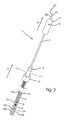
- Fig. 1 shows, in perspective, a general view of a bipolar electrosurgical instrument 1 connected to an electrosurgical generator 2.
- the bipolar electrosurgical instrument 1 has a hollow shaft 3 with a proximal end 4 and a distal end 5.
- the hollow shaft 3 is defined at least by an outer tubular casing 6 inside which an inner tubular casing 7 extends reciprocatingly.
- the outer tubular 6 casing has an exterior diameter of about 10 mm to ensure that it can pass smoothly through a conventional laparoscopic trocar port of same diameter.
- the inner tubular casing 7 accommodates, as indicated by dashed line, the loop electrode 8, such as an electrically conductive resilient looped wire, which is electrically connected to the electrosurgical generator 2, exemplified at circuit B, via electric wire B1, to enable electrosurgical cutting.
- the loop electrode 8 such as an electrically conductive resilient looped wire, which is electrically connected to the electrosurgical generator 2, exemplified at circuit B, via electric wire B1, to enable electrosurgical cutting.
- a first handle 9 at the proximal end of the inner tubular casing 7 has an actuation knob 10 which is connected to circuit B via electric wire B2 to enable the surgeon to switch cutting current on and off on demand and according to the surgeons choice only by a simple pressure on the actuation knob 10.
- the first handle is used for reciprocating the loop electrode as indicated with arrow P in the figures.
- the loop of the loop electrode 8 has an uninsulated cutting part 8a of e.g. 40 mm and an insulated part 8b ensuring that heat application to an object is confined to a limited and controlled area still maintaining a firm grip at the object, e.g. the uterus.
- Circuit B may be implemented in a separate device to be used together with a conventional bipolar electrosurgical generator and the electrosurgical instrument according to the present invention, or circuit B can be integrated in a new electrosurgical generator specifically designed for the present invention.
- Each return electrode 11a,11b,11c,11b have a distal end configured as a flat conductive plate or blade 12a,12b,12c,12d of enlarged surface area to establish good contact with an object (not shown) to be cut.
- the proximal end of three of the return electrodes e.g.
- Transmission of a signal representing the measured impedance, resistance or capacity from circuit C to circuit B is in the case shown integrated in the bipolar electrosurgical generator and takes place via dashed line D.
- the outer tubular 6 casing has at its proximal end 4 a number of longitudinal slide grooves 13a,13b,13c,13d, og which only two can be seen in fig. 1 and fig. 1a .
- the number of slide grooves 13a,13b,13c,13d corresponds to the number of return electrodes 11a,11b,11c,11d.
- the proximal ends of the return electrodes 11a,11b,11c,11d are passed through the corresponding slide grooves 13a,13b,13c,13d and secured to a second handle 14 for reciprocating, as indicated with the arrow A, said return electrodes 12a,12b,12c,12d in and out of the distal end 5 of the hollow shaft 3 as occasion requires.
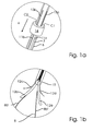
- the flat conductive blades or plates 12a,12,b,12c,12d of the return electrodes 11a,11b,11c,11d are curving outwards when emerged from the distal end 5 of the hollow shaft 2 and surrounding the loop electrode 8.
- the curvature should be sufficient to provide the flat conductive blades or plates 12a,12b,12c,12d with sufficient spring force to by themselves and instantly spread apart as a flower opens when emerged from the distal end 5 of the hollow shaft 3 and sufficiently flexible to yield to be retracted inside said distal end again as shown in the fragmentary perspective view of fig. 2 .
- the conductive blades of the return electrodes are shown as flat rectangular plates other outlines and geometries are foreseen within the scope of the present invention.
- Fig. 3 shows, seen in perspective and in a fragmentary enlarged view, the bipolar electrosurgical instrument 1 with the return electrodes 11a,11b,11c,11d emerged and the loop electrode 8 retracted, corresponding to step b of the method according to the disclosure.
- the second handle 14 is manually advanced towards the distal end 5 of the hollow shaft 3 so that the distance to the first handle 9 is increased but still leaving the loop electrode 8 hidden inside the distal end 5.
- Fig. 4a shows the method step c shown in fig. 4 , in an even more enlarged scale how the two legs 8b',8b " of the loop electrode 8 extends lengthwise inside the outer tubular casing 6 between the return electrodes 11a,11b,11c,11d.
- the return electrodes 11a,11b,11c,11d are firmly secured to the flat conductive blades 12a,12b,12c,12d.
- the return electrodes 11a,11b,11c,11d are long conductive rods securely hooked to flat conductive plates 12a,12b,12c,12d, however the return electrode may quite as well be a manufactured as a single unit or the rods may be welded to the plates or any other suitable conductive coupling together.
- Fig. 4a also illustrates how the guide plug 15 at the distal terminal end of the inner tubular casing 7 serves for holding the return electrodes 11a,11b,11c,11d in the circumferential space 16 between the outer tubular casing 6 and the inner tubular casing 7.
- Figs. 5, 6 and 7 shows in a perspective fragmentary view the intermediate situations showing step c where the loop of the loop electrode is arranged to encircle an exemplary indicated object 17 to be cut to step g where the object has been divided in tow parts.
- Fig. 5 shows the touching location of the object 17 between the return electrodes 11a,11b,11c,11d decreasing the value of the impedance, resistance or capacity measured by circuit C of the bipolar electrosurgical generator 2.
- circuit C Once circuit C has measured the size of the value of the impedance, resistance or capacity it compares the measured value with a predetermined value. If the measured value is below or equal to the predetermined value circuit C provides a signal to the surgeon, such as e.g. by means of a signal lamp on the electrosurgical generator flashing green, indicating that step d - g can be initiated to start the bipolar electrosurgical cutting procedure.
- Fig. 7 shows, seen in perspective, step g, where the object 17 has been cut in two pieces 17a,17b and the loop electrode 8 is fully retracted inside the hollow shaft 3 again.
- the pieces 17a,17b are catched and hold by a forceps introduced through another laparoscopic port.
- the forceps has a firm grip at the object 17 or pieces 17a,17b of object so that the method can be repeated for as many bipolar electrosurgical cuttings as required, e.g. until the object is cut into 10-20 smaller pathologically intact pieces.
- Monitoring is made using camera means introduced through yet another laparoscopic port, and the cut object pieces 17a,17b,....,17n may be collected in a receptacle introduced through yet another laparoscopic port, which receptacle is remove after the laparoscopic port has been removed.
- the whole surgical procedure will take about 10 min. allowing the surgeon to treat more patients than hitherto.
- the bipolar electrosurgical instrument is, as mentioned above, particular suited for LASH, which is a partial hysterectomy that preserves the cervix, and the ovaries, removing only the diseased uterus.
- the ligaments and blood vessels are detached from the uterus and cauterized using an electrosurgical instrument.
- the uterus corpus is transected from the cervix at the level of the internal os.
- the resected uterus can according to the present invention be further sectioned and removed as intact pieces of a size allowed by the diameters of the laparoscopic ports.
- the risk of accidental injuring surrounding tissue e.g the rectum, bladder, and pelvic sidewall is minimal.
Claims (7)
- Bipolares elektrochirurgisches Instrument (1), das an einen elektrochirurgischen Generator (2) anschließbar ist, wobei das bipolare elektrochirurgische Instrument (1) Folgendes umfasst:- einen hohlen Schaft (3), der dimensioniert ist, um durch einen laparoskopischen Zugang zu passen, und der ein proximales Ende (4) und ein distales Ende (5) aufweist,- eine Schlingenelektrode (8), die aus einem elektrisch leitfähigen, federnden Schlingendraht besteht, der mit einem ersten Mittel (9) versehen ist, um die Schlingenelektrode (8) zwischen einer eingezogenen Position im Innern des hohlen Schafts (3) und einer zweiten Position, in der mindestens ein Teil der Schlingenelektrode (8) aus dem distalen Ende (5) des hohlen Schafts (3) hervortritt, hin und her zu bewegen, und- mindestens zwei Rücklaufelektroden (11a, 11b, 11c, 11d), die mit zweiten Mitteln (13a, 13b, 13c, 13d, 14) versehen sind, um die mindestens zwei Rücklaufelektroden (11a, 11b, 11c, 11d) zwischen einer eingezogenen Position im Innern des hohlen Schafts (3) und einer zweiten Position, in der mindestens ein Teil der Rücklaufelektroden (11a, 11b, 11c, 11d) aus dem distalen Ende (5) des hohlen Schafts (3) hervortritt, hin und her zu bewegen,wobei im Gebrauch(a) der Schlingendraht der Schlingenelektrode um ein Gewebeobjekt herum angeordnet werden kann, wenn sich die Schlingenelektrode in der zweiten Position befindet,(b) und dann zusammengezogen werden kann, indem die Schlingenelektrode in Richtung auf die eingezogene Position eingezogen wird, wodurch die Rücklaufelektroden einen direkten Kontakt mit dem Gewebeobjekt erzielen können,dadurch gekennzeichnet, dass- das bipolare elektrochirurgische Instrument (1) ferner ein drittes Mittel (C) umfasst, um die Impedanz, den Widerstand oder die Kapazität in dem Gewebeobjekt zwischen den mindestens zwei Rücklaufelektroden (11a, 11b, 11c, 11d) zu messen, wenn sich die Rücklaufelektroden in direktem Kontakt mit dem Gewebeobjekt befinden, und- ein viertes Mittel (B) umfasst, um Energie an die Schlingenelektrode anzulegen, wenn der Wert der Impedanz, des Widerstandes oder der Kapazität unter einem vorherbestimmten Wert und/oder in einem vorherbestimmten Zeitraum liegt.
- Bipolares elektrochirurgisches Instrument (1) nach Anspruch 1, dadurch gekennzeichnet, dass die Rücklaufelektroden (11a, 11b, 11c, 11d) koaxial zur Schlingenelektrode (8) angeordnet sind, mindestens wenn die Schlingenelektrode (8) aus dem proximalen Ende (5) des hohlen Schafts (3) heraustritt.
- Bipolares elektrochirurgisches Instrument (1) nach einem der Ansprüche 1 oder 2, dadurch gekennzeichnet, dass mindestens ein Teil (8a, 8b', 8b") der Schlinge der Schlingenelektrode (8) angeordnet ist, um zwischen den herausgetretenen Rücklaufelektroden (11a, 11b, 11c, 11d) herauszutreten.
- Bipolares elektrochirurgisches Instrument (1) nach einem der Ansprüche 1, 2 oder 3, dadurch gekennzeichnet, dass das bipolare elektrochirurgische Instrument (1) mindestens vier Rücklaufelektroden (11a, 11b, 11c, 11d) umfasst.
- Bipolares elektrochirurgisches Instrument (1) nach einem der vorhergehenden Ansprüche 1 bis 4, dadurch gekennzeichnet, dass die Rücklaufelektroden (11a, 11b, 11c, 11d) aus flachen Plättchen oder Lamellen (12a, 12b, 12c, 12d) bevorzugt aus Edelstahl bestehen.
- Bipolares elektrochirurgisches Instrument (1) nach einem der vorhergehenden Ansprüche 1 bis 5, wobei das Instrument ferner den elektrochirurgischen Generator umfasst, wobei das Instrument ferner dadurch gekennzeichnet ist, dass das vierte Mittel (B) zum Anlegen von Energie an die Schlingenelektrode (3) und das dritte Mittel (C) zum Messen der Impedanz, des Widerstandes oder der Kapazität, in den elektrochirurgischen Generator (2) integriert sind.
- Bipolares elektrochirurgisches Instrument (1) nach einem der vorhergehenden Ansprüche 1 bis 6, dadurch gekennzeichnet, dass der hohle Schaft (3) ein äußeres röhrenförmiges Gehäuse (6) umfasst, das eine längsgerichtete Gleitrille (13a, 13b, 13c, 13d) umfasst, um die Rücklaufelektroden (11a, 11b, 11c, 11d) hin und her zu bewegen, und ein inneres röhrenförmiges Gehäuse (7) umfasst, das die Schlingenelektrode (8) aufnimmt, wobei das innere röhrenförmige Gehäuse (7) gegenüber dem äußeren röhrenförmigen Gehäuse (6) isoliert ist.
Priority Applications (2)
| Application Number | Priority Date | Filing Date | Title |
|---|---|---|---|
| EP09151319.2A EP2210567B1 (de) | 2009-01-26 | 2009-01-26 | Bipolares elektrochirurgisches Instrument |
| US12/686,888 US20100191238A1 (en) | 2009-01-26 | 2010-01-13 | Bipolar electrosurgical instrument and method of using it |
Applications Claiming Priority (1)
| Application Number | Priority Date | Filing Date | Title |
|---|---|---|---|
| EP09151319.2A EP2210567B1 (de) | 2009-01-26 | 2009-01-26 | Bipolares elektrochirurgisches Instrument |
Publications (2)
| Publication Number | Publication Date |
|---|---|
| EP2210567A1 EP2210567A1 (de) | 2010-07-28 |
| EP2210567B1 true EP2210567B1 (de) | 2013-07-31 |
Family
ID=40383566
Family Applications (1)
| Application Number | Title | Priority Date | Filing Date |
|---|---|---|---|
| EP09151319.2A Active EP2210567B1 (de) | 2009-01-26 | 2009-01-26 | Bipolares elektrochirurgisches Instrument |
Country Status (2)
| Country | Link |
|---|---|
| US (1) | US20100191238A1 (de) |
| EP (1) | EP2210567B1 (de) |
Families Citing this family (9)
| Publication number | Priority date | Publication date | Assignee | Title |
|---|---|---|---|---|
| AU2011292747A1 (en) * | 2010-08-19 | 2013-03-14 | Syneron Medical Ltd. | Electromagnetic energy applicator for personal aesthetic skin treatment |
| EP2540243B1 (de) * | 2011-06-28 | 2020-02-26 | Lina Medical ApS | Elektrochirurgisches instrument |
| EP2540242B1 (de) | 2011-06-28 | 2014-05-21 | Lina Medical ApS | Elektrochirurgisches Instrument und Apparat für dieses Instrument |
| JP6095507B2 (ja) * | 2013-06-28 | 2017-03-15 | オリンパス株式会社 | 内視鏡システム |
| WO2016109207A1 (en) * | 2014-12-31 | 2016-07-07 | St. Jude Medical, Cardiology Division, Inc. | Filter circuit for electrophysiology system |
| CN106344149A (zh) * | 2016-10-10 | 2017-01-25 | 南京市第医院 | 一种电灼圈套器 |
| US11903636B2 (en) * | 2018-09-27 | 2024-02-20 | Covidien Lp | Energy-based tissue specimen removal |
| US20220110680A1 (en) * | 2020-10-08 | 2022-04-14 | Gyrus Acmi, Inc. D/B/A Olympus Surgical Technologies America | Uterine manipulator with neutral return electrode |
| CN113633346A (zh) * | 2021-08-31 | 2021-11-12 | 苏州中荟医疗科技有限公司 | 一种电极装置及冲击波发生系统 |
Family Cites Families (9)
| Publication number | Priority date | Publication date | Assignee | Title |
|---|---|---|---|---|
| CA2121861A1 (en) | 1993-04-23 | 1994-10-24 | William D. Fox | Mechanical morcellator |
| WO2002032335A1 (en) * | 2000-07-25 | 2002-04-25 | Rita Medical Systems Inc. | Apparatus for detecting and treating tumors using localized impedance measurement |
| GB2374532B (en) * | 2001-02-23 | 2004-10-06 | Smiths Group Plc | Electrosurgery apparatus |
| DE10226040A1 (de) * | 2002-06-12 | 2003-12-24 | Bayer Ag | Verfahren zur Herstellung von Carbonsäurebenzylestern |
| EP1529495B1 (de) * | 2002-06-18 | 2016-10-05 | Olympus Corporation | Resektoskop |
| US8512333B2 (en) * | 2005-07-01 | 2013-08-20 | Halt Medical Inc. | Anchored RF ablation device for the destruction of tissue masses |
| US7789881B2 (en) * | 2005-08-25 | 2010-09-07 | Boston Scientific Scimed, Inc. | Endoscopic resection method |
| EP2043540A2 (de) * | 2006-07-10 | 2009-04-08 | Lina Medical ApS | Elektrochirurgisches instrument |
| WO2008063195A1 (en) * | 2006-10-12 | 2008-05-29 | St. Jude Medical, Atrial Fibrillation Division, Inc. | Assessment of electrode coupling for tissue ablation |
-
2009
- 2009-01-26 EP EP09151319.2A patent/EP2210567B1/de active Active
-
2010
- 2010-01-13 US US12/686,888 patent/US20100191238A1/en not_active Abandoned
Also Published As
| Publication number | Publication date |
|---|---|
| EP2210567A1 (de) | 2010-07-28 |
| US20100191238A1 (en) | 2010-07-29 |
Similar Documents
| Publication | Publication Date | Title |
|---|---|---|
| EP2210567B1 (de) | Bipolares elektrochirurgisches Instrument | |
| US6692445B2 (en) | Biopsy sampler | |
| US5158561A (en) | Monopolar polypectomy snare with coagulation electrode | |
| JP5351019B2 (ja) | 切除装置 | |
| CA2535467C (en) | Electrosurgical device | |
| JP5814569B2 (ja) | 重要な構造に対する近接を決定するためのシステムおよび方法 | |
| EP0955921B1 (de) | Schlingenelektroden für elektrokauterisationssonden zum einsatz bei einem resektoskop | |
| EP2364661B1 (de) | System und Verfahren zur Bestimmung der Nähe zu einer kritischen Struktur | |
| EP1897506B1 (de) | Chirurgisches Instrument zur kontrollierten Durchführung von Myotomien | |
| JP2007527766A (ja) | 多機能伸縮な自在単極性/双極性外科用デバイスおよびそのための方法 | |
| EP0536998A2 (de) | Monopolare elektrochirurgische Vorrichtung mit Spül- und Saugkontrolle für endoskopische Chirurgie | |
| US11071579B2 (en) | Bipolar cutting and hemostasis blade system | |
| BRPI1106889A2 (pt) | instrumento elevador de cobb eletrocirérgico | |
| US6346106B1 (en) | Instrument and method employing snare electrode windable about rotatable spool for minimally invasive electrosurgical resection | |
| US20080009858A1 (en) | Laparoscopic instrument tip and method of specimen collection | |
| US10548656B2 (en) | Multi-functional surgical cautery device, system and method of use | |
| US8992525B2 (en) | Surgical instrument | |
| EP3052039B1 (de) | Bipolare koagulationssonde und schlinge | |
| US20050149016A1 (en) | Laparoscopic device and method of female sterilization | |
| JP2019532770A (ja) | 電気外科システム用のアタッチメント | |
| JPH1014922A (ja) | 臓器細切器および臓器細切装置 | |
| JP2003305055A (ja) | レゼクトスコープ装置 | |
| CN110897707A (zh) | 一种新型开放手术带深部照明吸烟测量功能混合型刀头单极消融电极 | |
| CN212547157U (zh) | 一种快速更换刀头多用电凝吸管 | |
| US11324547B2 (en) | Electrosurgical probe and kit and method of using |
Legal Events
| Date | Code | Title | Description |
|---|---|---|---|
| PUAI | Public reference made under article 153(3) epc to a published international application that has entered the european phase |
Free format text: ORIGINAL CODE: 0009012 |
|
| AK | Designated contracting states |
Kind code of ref document: A1 Designated state(s): AT BE BG CH CY CZ DE DK EE ES FI FR GB GR HR HU IE IS IT LI LT LU LV MC MK MT NL NO PL PT RO SE SI SK TR |
|
| AX | Request for extension of the european patent |
Extension state: AL BA RS |
|
| 17P | Request for examination filed |
Effective date: 20110128 |
|
| 17Q | First examination report despatched |
Effective date: 20110217 |
|
| AKX | Designation fees paid |
Designated state(s): AT BE BG CH CY CZ DE DK EE ES FI FR GB GR HR HU IE IS IT LI LT LU LV MC MK MT NL NO PL PT RO SE SI SK TR |
|
| AXX | Extension fees paid |
Extension state: RS Payment date: 20110128 Extension state: AL Payment date: 20110128 Extension state: BA Payment date: 20110128 |
|
| GRAP | Despatch of communication of intention to grant a patent |
Free format text: ORIGINAL CODE: EPIDOSNIGR1 |
|
| GRAS | Grant fee paid |
Free format text: ORIGINAL CODE: EPIDOSNIGR3 |
|
| GRAA | (expected) grant |
Free format text: ORIGINAL CODE: 0009210 |
|
| AK | Designated contracting states |
Kind code of ref document: B1 Designated state(s): AT BE BG CH CY CZ DE DK EE ES FI FR GB GR HR HU IE IS IT LI LT LU LV MC MK MT NL NO PL PT RO SE SI SK TR |
|
| AX | Request for extension of the european patent |
Extension state: AL BA RS |
|
| REG | Reference to a national code |
Ref country code: GB Ref legal event code: FG4D Ref country code: CH Ref legal event code: EP |
|
| REG | Reference to a national code |
Ref country code: AT Ref legal event code: REF Ref document number: 624153 Country of ref document: AT Kind code of ref document: T Effective date: 20130815 |
|
| REG | Reference to a national code |
Ref country code: IE Ref legal event code: FG4D |
|
| REG | Reference to a national code |
Ref country code: DE Ref legal event code: R096 Ref document number: 602009017542 Country of ref document: DE Effective date: 20130926 |
|
| REG | Reference to a national code |
Ref country code: NL Ref legal event code: T3 |
|
| REG | Reference to a national code |
Ref country code: AT Ref legal event code: MK05 Ref document number: 624153 Country of ref document: AT Kind code of ref document: T Effective date: 20130731 |
|
| REG | Reference to a national code |
Ref country code: LT Ref legal event code: MG4D |
|
| PG25 | Lapsed in a contracting state [announced via postgrant information from national office to epo] |
Ref country code: LT Free format text: LAPSE BECAUSE OF FAILURE TO SUBMIT A TRANSLATION OF THE DESCRIPTION OR TO PAY THE FEE WITHIN THE PRESCRIBED TIME-LIMIT Effective date: 20130731 Ref country code: SE Free format text: LAPSE BECAUSE OF FAILURE TO SUBMIT A TRANSLATION OF THE DESCRIPTION OR TO PAY THE FEE WITHIN THE PRESCRIBED TIME-LIMIT Effective date: 20130731 Ref country code: NO Free format text: LAPSE BECAUSE OF FAILURE TO SUBMIT A TRANSLATION OF THE DESCRIPTION OR TO PAY THE FEE WITHIN THE PRESCRIBED TIME-LIMIT Effective date: 20131031 Ref country code: BE Free format text: LAPSE BECAUSE OF FAILURE TO SUBMIT A TRANSLATION OF THE DESCRIPTION OR TO PAY THE FEE WITHIN THE PRESCRIBED TIME-LIMIT Effective date: 20130731 Ref country code: IS Free format text: LAPSE BECAUSE OF FAILURE TO SUBMIT A TRANSLATION OF THE DESCRIPTION OR TO PAY THE FEE WITHIN THE PRESCRIBED TIME-LIMIT Effective date: 20131130 Ref country code: PT Free format text: LAPSE BECAUSE OF FAILURE TO SUBMIT A TRANSLATION OF THE DESCRIPTION OR TO PAY THE FEE WITHIN THE PRESCRIBED TIME-LIMIT Effective date: 20131202 Ref country code: AT Free format text: LAPSE BECAUSE OF FAILURE TO SUBMIT A TRANSLATION OF THE DESCRIPTION OR TO PAY THE FEE WITHIN THE PRESCRIBED TIME-LIMIT Effective date: 20130731 Ref country code: CY Free format text: LAPSE BECAUSE OF FAILURE TO SUBMIT A TRANSLATION OF THE DESCRIPTION OR TO PAY THE FEE WITHIN THE PRESCRIBED TIME-LIMIT Effective date: 20130904 Ref country code: HR Free format text: LAPSE BECAUSE OF FAILURE TO SUBMIT A TRANSLATION OF THE DESCRIPTION OR TO PAY THE FEE WITHIN THE PRESCRIBED TIME-LIMIT Effective date: 20130731 |
|
| PG25 | Lapsed in a contracting state [announced via postgrant information from national office to epo] |
Ref country code: ES Free format text: LAPSE BECAUSE OF FAILURE TO SUBMIT A TRANSLATION OF THE DESCRIPTION OR TO PAY THE FEE WITHIN THE PRESCRIBED TIME-LIMIT Effective date: 20130731 Ref country code: GR Free format text: LAPSE BECAUSE OF FAILURE TO SUBMIT A TRANSLATION OF THE DESCRIPTION OR TO PAY THE FEE WITHIN THE PRESCRIBED TIME-LIMIT Effective date: 20131101 Ref country code: SI Free format text: LAPSE BECAUSE OF FAILURE TO SUBMIT A TRANSLATION OF THE DESCRIPTION OR TO PAY THE FEE WITHIN THE PRESCRIBED TIME-LIMIT Effective date: 20130731 Ref country code: FI Free format text: LAPSE BECAUSE OF FAILURE TO SUBMIT A TRANSLATION OF THE DESCRIPTION OR TO PAY THE FEE WITHIN THE PRESCRIBED TIME-LIMIT Effective date: 20130731 Ref country code: PL Free format text: LAPSE BECAUSE OF FAILURE TO SUBMIT A TRANSLATION OF THE DESCRIPTION OR TO PAY THE FEE WITHIN THE PRESCRIBED TIME-LIMIT Effective date: 20130731 Ref country code: LV Free format text: LAPSE BECAUSE OF FAILURE TO SUBMIT A TRANSLATION OF THE DESCRIPTION OR TO PAY THE FEE WITHIN THE PRESCRIBED TIME-LIMIT Effective date: 20130731 |
|
| PG25 | Lapsed in a contracting state [announced via postgrant information from national office to epo] |
Ref country code: CY Free format text: LAPSE BECAUSE OF FAILURE TO SUBMIT A TRANSLATION OF THE DESCRIPTION OR TO PAY THE FEE WITHIN THE PRESCRIBED TIME-LIMIT Effective date: 20130731 |
|
| PG25 | Lapsed in a contracting state [announced via postgrant information from national office to epo] |
Ref country code: CZ Free format text: LAPSE BECAUSE OF FAILURE TO SUBMIT A TRANSLATION OF THE DESCRIPTION OR TO PAY THE FEE WITHIN THE PRESCRIBED TIME-LIMIT Effective date: 20130731 Ref country code: EE Free format text: LAPSE BECAUSE OF FAILURE TO SUBMIT A TRANSLATION OF THE DESCRIPTION OR TO PAY THE FEE WITHIN THE PRESCRIBED TIME-LIMIT Effective date: 20130731 Ref country code: RO Free format text: LAPSE BECAUSE OF FAILURE TO SUBMIT A TRANSLATION OF THE DESCRIPTION OR TO PAY THE FEE WITHIN THE PRESCRIBED TIME-LIMIT Effective date: 20130731 Ref country code: SK Free format text: LAPSE BECAUSE OF FAILURE TO SUBMIT A TRANSLATION OF THE DESCRIPTION OR TO PAY THE FEE WITHIN THE PRESCRIBED TIME-LIMIT Effective date: 20130731 Ref country code: DK Free format text: LAPSE BECAUSE OF FAILURE TO SUBMIT A TRANSLATION OF THE DESCRIPTION OR TO PAY THE FEE WITHIN THE PRESCRIBED TIME-LIMIT Effective date: 20130731 |
|
| PG25 | Lapsed in a contracting state [announced via postgrant information from national office to epo] |
Ref country code: IT Free format text: LAPSE BECAUSE OF FAILURE TO SUBMIT A TRANSLATION OF THE DESCRIPTION OR TO PAY THE FEE WITHIN THE PRESCRIBED TIME-LIMIT Effective date: 20130731 |
|
| PLBE | No opposition filed within time limit |
Free format text: ORIGINAL CODE: 0009261 |
|
| STAA | Information on the status of an ep patent application or granted ep patent |
Free format text: STATUS: NO OPPOSITION FILED WITHIN TIME LIMIT |
|
| 26N | No opposition filed |
Effective date: 20140502 |
|
| REG | Reference to a national code |
Ref country code: DE Ref legal event code: R097 Ref document number: 602009017542 Country of ref document: DE Effective date: 20140502 |
|
| PG25 | Lapsed in a contracting state [announced via postgrant information from national office to epo] |
Ref country code: MC Free format text: LAPSE BECAUSE OF FAILURE TO SUBMIT A TRANSLATION OF THE DESCRIPTION OR TO PAY THE FEE WITHIN THE PRESCRIBED TIME-LIMIT Effective date: 20130731 Ref country code: LU Free format text: LAPSE BECAUSE OF FAILURE TO SUBMIT A TRANSLATION OF THE DESCRIPTION OR TO PAY THE FEE WITHIN THE PRESCRIBED TIME-LIMIT Effective date: 20140126 |
|
| REG | Reference to a national code |
Ref country code: CH Ref legal event code: PL |
|
| PG25 | Lapsed in a contracting state [announced via postgrant information from national office to epo] |
Ref country code: LI Free format text: LAPSE BECAUSE OF NON-PAYMENT OF DUE FEES Effective date: 20140131 Ref country code: CH Free format text: LAPSE BECAUSE OF NON-PAYMENT OF DUE FEES Effective date: 20140131 |
|
| REG | Reference to a national code |
Ref country code: IE Ref legal event code: MM4A |
|
| PG25 | Lapsed in a contracting state [announced via postgrant information from national office to epo] |
Ref country code: IE Free format text: LAPSE BECAUSE OF NON-PAYMENT OF DUE FEES Effective date: 20140126 |
|
| REG | Reference to a national code |
Ref country code: FR Ref legal event code: PLFP Year of fee payment: 7 |
|
| REG | Reference to a national code |
Ref country code: FR Ref legal event code: PLFP Year of fee payment: 8 |
|
| PG25 | Lapsed in a contracting state [announced via postgrant information from national office to epo] |
Ref country code: MT Free format text: LAPSE BECAUSE OF FAILURE TO SUBMIT A TRANSLATION OF THE DESCRIPTION OR TO PAY THE FEE WITHIN THE PRESCRIBED TIME-LIMIT Effective date: 20130731 |
|
| PG25 | Lapsed in a contracting state [announced via postgrant information from national office to epo] |
Ref country code: BG Free format text: LAPSE BECAUSE OF FAILURE TO SUBMIT A TRANSLATION OF THE DESCRIPTION OR TO PAY THE FEE WITHIN THE PRESCRIBED TIME-LIMIT Effective date: 20130731 |
|
| PG25 | Lapsed in a contracting state [announced via postgrant information from national office to epo] |
Ref country code: TR Free format text: LAPSE BECAUSE OF FAILURE TO SUBMIT A TRANSLATION OF THE DESCRIPTION OR TO PAY THE FEE WITHIN THE PRESCRIBED TIME-LIMIT Effective date: 20130731 Ref country code: HU Free format text: LAPSE BECAUSE OF FAILURE TO SUBMIT A TRANSLATION OF THE DESCRIPTION OR TO PAY THE FEE WITHIN THE PRESCRIBED TIME-LIMIT; INVALID AB INITIO Effective date: 20090126 |
|
| REG | Reference to a national code |
Ref country code: FR Ref legal event code: PLFP Year of fee payment: 9 |
|
| REG | Reference to a national code |
Ref country code: FR Ref legal event code: PLFP Year of fee payment: 10 |
|
| PG25 | Lapsed in a contracting state [announced via postgrant information from national office to epo] |
Ref country code: MK Free format text: LAPSE BECAUSE OF FAILURE TO SUBMIT A TRANSLATION OF THE DESCRIPTION OR TO PAY THE FEE WITHIN THE PRESCRIBED TIME-LIMIT Effective date: 20130731 |
|
| REG | Reference to a national code |
Ref country code: GB Ref legal event code: 732E Free format text: REGISTERED BETWEEN 20210211 AND 20210217 |
|
| REG | Reference to a national code |
Ref country code: NL Ref legal event code: PD Owner name: LINA MEDICAL INTERNATIONAL OPERATIONS AG; CH Free format text: DETAILS ASSIGNMENT: CHANGE OF OWNER(S), ASSIGNMENT; FORMER OWNER NAME: LINA MEDICAL APS Effective date: 20210318 |
|
| REG | Reference to a national code |
Ref country code: DE Ref legal event code: R081 Ref document number: 602009017542 Country of ref document: DE Owner name: LINA MEDICAL INTERNATIONAL OPERATIONS AG, CH Free format text: FORMER OWNER: LINA MEDICAL APS, GLOSTRUP, DK |
|
| PGFP | Annual fee paid to national office [announced via postgrant information from national office to epo] |
Ref country code: FR Payment date: 20230113 Year of fee payment: 15 |
|
| PGFP | Annual fee paid to national office [announced via postgrant information from national office to epo] |
Ref country code: GB Payment date: 20230118 Year of fee payment: 15 Ref country code: DE Payment date: 20230119 Year of fee payment: 15 |
|
| PGFP | Annual fee paid to national office [announced via postgrant information from national office to epo] |
Ref country code: NL Payment date: 20230117 Year of fee payment: 15 |
|
| PGFP | Annual fee paid to national office [announced via postgrant information from national office to epo] |
Ref country code: NL Payment date: 20240116 Year of fee payment: 16 |