EP2209660B1 - Dispositif de transmission de puissance entre une sortie d'un moteur thermique et un arbre de roues et utilisation de ce dispositif - Google Patents
Dispositif de transmission de puissance entre une sortie d'un moteur thermique et un arbre de roues et utilisation de ce dispositif Download PDFInfo
- Publication number
- EP2209660B1 EP2209660B1 EP08855726A EP08855726A EP2209660B1 EP 2209660 B1 EP2209660 B1 EP 2209660B1 EP 08855726 A EP08855726 A EP 08855726A EP 08855726 A EP08855726 A EP 08855726A EP 2209660 B1 EP2209660 B1 EP 2209660B1
- Authority
- EP
- European Patent Office
- Prior art keywords
- gear
- machine
- shaft
- stator
- ratio
- Prior art date
- Legal status (The legal status is an assumption and is not a legal conclusion. Google has not performed a legal analysis and makes no representation as to the accuracy of the status listed.)
- Not-in-force
Links
Images


Classifications
-
- B—PERFORMING OPERATIONS; TRANSPORTING
- B60—VEHICLES IN GENERAL
- B60K—ARRANGEMENT OR MOUNTING OF PROPULSION UNITS OR OF TRANSMISSIONS IN VEHICLES; ARRANGEMENT OR MOUNTING OF PLURAL DIVERSE PRIME-MOVERS IN VEHICLES; AUXILIARY DRIVES FOR VEHICLES; INSTRUMENTATION OR DASHBOARDS FOR VEHICLES; ARRANGEMENTS IN CONNECTION WITH COOLING, AIR INTAKE, GAS EXHAUST OR FUEL SUPPLY OF PROPULSION UNITS IN VEHICLES
- B60K6/00—Arrangement or mounting of plural diverse prime-movers for mutual or common propulsion, e.g. hybrid propulsion systems comprising electric motors and internal combustion engines ; Control systems therefor, i.e. systems controlling two or more prime movers, or controlling one of these prime movers and any of the transmission, drive or drive units Informative references: mechanical gearings with secondary electric drive F16H3/72; arrangements for handling mechanical energy structurally associated with the dynamo-electric machine H02K7/00; machines comprising structurally interrelated motor and generator parts H02K51/00; dynamo-electric machines not otherwise provided for in H02K see H02K99/00
- B60K6/20—Arrangement or mounting of plural diverse prime-movers for mutual or common propulsion, e.g. hybrid propulsion systems comprising electric motors and internal combustion engines ; Control systems therefor, i.e. systems controlling two or more prime movers, or controlling one of these prime movers and any of the transmission, drive or drive units Informative references: mechanical gearings with secondary electric drive F16H3/72; arrangements for handling mechanical energy structurally associated with the dynamo-electric machine H02K7/00; machines comprising structurally interrelated motor and generator parts H02K51/00; dynamo-electric machines not otherwise provided for in H02K see H02K99/00 the prime-movers consisting of electric motors and internal combustion engines, e.g. HEVs
- B60K6/42—Arrangement or mounting of plural diverse prime-movers for mutual or common propulsion, e.g. hybrid propulsion systems comprising electric motors and internal combustion engines ; Control systems therefor, i.e. systems controlling two or more prime movers, or controlling one of these prime movers and any of the transmission, drive or drive units Informative references: mechanical gearings with secondary electric drive F16H3/72; arrangements for handling mechanical energy structurally associated with the dynamo-electric machine H02K7/00; machines comprising structurally interrelated motor and generator parts H02K51/00; dynamo-electric machines not otherwise provided for in H02K see H02K99/00 the prime-movers consisting of electric motors and internal combustion engines, e.g. HEVs characterised by the architecture of the hybrid electric vehicle
- B60K6/44—Series-parallel type
- B60K6/448—Electrical distribution type
-
- B—PERFORMING OPERATIONS; TRANSPORTING
- B60—VEHICLES IN GENERAL
- B60K—ARRANGEMENT OR MOUNTING OF PROPULSION UNITS OR OF TRANSMISSIONS IN VEHICLES; ARRANGEMENT OR MOUNTING OF PLURAL DIVERSE PRIME-MOVERS IN VEHICLES; AUXILIARY DRIVES FOR VEHICLES; INSTRUMENTATION OR DASHBOARDS FOR VEHICLES; ARRANGEMENTS IN CONNECTION WITH COOLING, AIR INTAKE, GAS EXHAUST OR FUEL SUPPLY OF PROPULSION UNITS IN VEHICLES
- B60K6/00—Arrangement or mounting of plural diverse prime-movers for mutual or common propulsion, e.g. hybrid propulsion systems comprising electric motors and internal combustion engines ; Control systems therefor, i.e. systems controlling two or more prime movers, or controlling one of these prime movers and any of the transmission, drive or drive units Informative references: mechanical gearings with secondary electric drive F16H3/72; arrangements for handling mechanical energy structurally associated with the dynamo-electric machine H02K7/00; machines comprising structurally interrelated motor and generator parts H02K51/00; dynamo-electric machines not otherwise provided for in H02K see H02K99/00
- B60K6/20—Arrangement or mounting of plural diverse prime-movers for mutual or common propulsion, e.g. hybrid propulsion systems comprising electric motors and internal combustion engines ; Control systems therefor, i.e. systems controlling two or more prime movers, or controlling one of these prime movers and any of the transmission, drive or drive units Informative references: mechanical gearings with secondary electric drive F16H3/72; arrangements for handling mechanical energy structurally associated with the dynamo-electric machine H02K7/00; machines comprising structurally interrelated motor and generator parts H02K51/00; dynamo-electric machines not otherwise provided for in H02K see H02K99/00 the prime-movers consisting of electric motors and internal combustion engines, e.g. HEVs
- B60K6/22—Arrangement or mounting of plural diverse prime-movers for mutual or common propulsion, e.g. hybrid propulsion systems comprising electric motors and internal combustion engines ; Control systems therefor, i.e. systems controlling two or more prime movers, or controlling one of these prime movers and any of the transmission, drive or drive units Informative references: mechanical gearings with secondary electric drive F16H3/72; arrangements for handling mechanical energy structurally associated with the dynamo-electric machine H02K7/00; machines comprising structurally interrelated motor and generator parts H02K51/00; dynamo-electric machines not otherwise provided for in H02K see H02K99/00 the prime-movers consisting of electric motors and internal combustion engines, e.g. HEVs characterised by apparatus, components or means specially adapted for HEVs
- B60K6/36—Arrangement or mounting of plural diverse prime-movers for mutual or common propulsion, e.g. hybrid propulsion systems comprising electric motors and internal combustion engines ; Control systems therefor, i.e. systems controlling two or more prime movers, or controlling one of these prime movers and any of the transmission, drive or drive units Informative references: mechanical gearings with secondary electric drive F16H3/72; arrangements for handling mechanical energy structurally associated with the dynamo-electric machine H02K7/00; machines comprising structurally interrelated motor and generator parts H02K51/00; dynamo-electric machines not otherwise provided for in H02K see H02K99/00 the prime-movers consisting of electric motors and internal combustion engines, e.g. HEVs characterised by apparatus, components or means specially adapted for HEVs characterised by the transmission gearings
- B60K6/365—Arrangement or mounting of plural diverse prime-movers for mutual or common propulsion, e.g. hybrid propulsion systems comprising electric motors and internal combustion engines ; Control systems therefor, i.e. systems controlling two or more prime movers, or controlling one of these prime movers and any of the transmission, drive or drive units Informative references: mechanical gearings with secondary electric drive F16H3/72; arrangements for handling mechanical energy structurally associated with the dynamo-electric machine H02K7/00; machines comprising structurally interrelated motor and generator parts H02K51/00; dynamo-electric machines not otherwise provided for in H02K see H02K99/00 the prime-movers consisting of electric motors and internal combustion engines, e.g. HEVs characterised by apparatus, components or means specially adapted for HEVs characterised by the transmission gearings with the gears having orbital motion
-
- B—PERFORMING OPERATIONS; TRANSPORTING
- B60—VEHICLES IN GENERAL
- B60K—ARRANGEMENT OR MOUNTING OF PROPULSION UNITS OR OF TRANSMISSIONS IN VEHICLES; ARRANGEMENT OR MOUNTING OF PLURAL DIVERSE PRIME-MOVERS IN VEHICLES; AUXILIARY DRIVES FOR VEHICLES; INSTRUMENTATION OR DASHBOARDS FOR VEHICLES; ARRANGEMENTS IN CONNECTION WITH COOLING, AIR INTAKE, GAS EXHAUST OR FUEL SUPPLY OF PROPULSION UNITS IN VEHICLES
- B60K6/00—Arrangement or mounting of plural diverse prime-movers for mutual or common propulsion, e.g. hybrid propulsion systems comprising electric motors and internal combustion engines ; Control systems therefor, i.e. systems controlling two or more prime movers, or controlling one of these prime movers and any of the transmission, drive or drive units Informative references: mechanical gearings with secondary electric drive F16H3/72; arrangements for handling mechanical energy structurally associated with the dynamo-electric machine H02K7/00; machines comprising structurally interrelated motor and generator parts H02K51/00; dynamo-electric machines not otherwise provided for in H02K see H02K99/00
- B60K6/20—Arrangement or mounting of plural diverse prime-movers for mutual or common propulsion, e.g. hybrid propulsion systems comprising electric motors and internal combustion engines ; Control systems therefor, i.e. systems controlling two or more prime movers, or controlling one of these prime movers and any of the transmission, drive or drive units Informative references: mechanical gearings with secondary electric drive F16H3/72; arrangements for handling mechanical energy structurally associated with the dynamo-electric machine H02K7/00; machines comprising structurally interrelated motor and generator parts H02K51/00; dynamo-electric machines not otherwise provided for in H02K see H02K99/00 the prime-movers consisting of electric motors and internal combustion engines, e.g. HEVs
- B60K6/22—Arrangement or mounting of plural diverse prime-movers for mutual or common propulsion, e.g. hybrid propulsion systems comprising electric motors and internal combustion engines ; Control systems therefor, i.e. systems controlling two or more prime movers, or controlling one of these prime movers and any of the transmission, drive or drive units Informative references: mechanical gearings with secondary electric drive F16H3/72; arrangements for handling mechanical energy structurally associated with the dynamo-electric machine H02K7/00; machines comprising structurally interrelated motor and generator parts H02K51/00; dynamo-electric machines not otherwise provided for in H02K see H02K99/00 the prime-movers consisting of electric motors and internal combustion engines, e.g. HEVs characterised by apparatus, components or means specially adapted for HEVs
- B60K6/38—Arrangement or mounting of plural diverse prime-movers for mutual or common propulsion, e.g. hybrid propulsion systems comprising electric motors and internal combustion engines ; Control systems therefor, i.e. systems controlling two or more prime movers, or controlling one of these prime movers and any of the transmission, drive or drive units Informative references: mechanical gearings with secondary electric drive F16H3/72; arrangements for handling mechanical energy structurally associated with the dynamo-electric machine H02K7/00; machines comprising structurally interrelated motor and generator parts H02K51/00; dynamo-electric machines not otherwise provided for in H02K see H02K99/00 the prime-movers consisting of electric motors and internal combustion engines, e.g. HEVs characterised by apparatus, components or means specially adapted for HEVs characterised by the driveline clutches
- B60K6/387—Actuated clutches, i.e. clutches engaged or disengaged by electric, hydraulic or mechanical actuating means
-
- B—PERFORMING OPERATIONS; TRANSPORTING
- B60—VEHICLES IN GENERAL
- B60K—ARRANGEMENT OR MOUNTING OF PROPULSION UNITS OR OF TRANSMISSIONS IN VEHICLES; ARRANGEMENT OR MOUNTING OF PLURAL DIVERSE PRIME-MOVERS IN VEHICLES; AUXILIARY DRIVES FOR VEHICLES; INSTRUMENTATION OR DASHBOARDS FOR VEHICLES; ARRANGEMENTS IN CONNECTION WITH COOLING, AIR INTAKE, GAS EXHAUST OR FUEL SUPPLY OF PROPULSION UNITS IN VEHICLES
- B60K6/00—Arrangement or mounting of plural diverse prime-movers for mutual or common propulsion, e.g. hybrid propulsion systems comprising electric motors and internal combustion engines ; Control systems therefor, i.e. systems controlling two or more prime movers, or controlling one of these prime movers and any of the transmission, drive or drive units Informative references: mechanical gearings with secondary electric drive F16H3/72; arrangements for handling mechanical energy structurally associated with the dynamo-electric machine H02K7/00; machines comprising structurally interrelated motor and generator parts H02K51/00; dynamo-electric machines not otherwise provided for in H02K see H02K99/00
- B60K6/20—Arrangement or mounting of plural diverse prime-movers for mutual or common propulsion, e.g. hybrid propulsion systems comprising electric motors and internal combustion engines ; Control systems therefor, i.e. systems controlling two or more prime movers, or controlling one of these prime movers and any of the transmission, drive or drive units Informative references: mechanical gearings with secondary electric drive F16H3/72; arrangements for handling mechanical energy structurally associated with the dynamo-electric machine H02K7/00; machines comprising structurally interrelated motor and generator parts H02K51/00; dynamo-electric machines not otherwise provided for in H02K see H02K99/00 the prime-movers consisting of electric motors and internal combustion engines, e.g. HEVs
- B60K6/42—Arrangement or mounting of plural diverse prime-movers for mutual or common propulsion, e.g. hybrid propulsion systems comprising electric motors and internal combustion engines ; Control systems therefor, i.e. systems controlling two or more prime movers, or controlling one of these prime movers and any of the transmission, drive or drive units Informative references: mechanical gearings with secondary electric drive F16H3/72; arrangements for handling mechanical energy structurally associated with the dynamo-electric machine H02K7/00; machines comprising structurally interrelated motor and generator parts H02K51/00; dynamo-electric machines not otherwise provided for in H02K see H02K99/00 the prime-movers consisting of electric motors and internal combustion engines, e.g. HEVs characterised by the architecture of the hybrid electric vehicle
- B60K6/44—Series-parallel type
- B60K6/445—Differential gearing distribution type
-
- F—MECHANICAL ENGINEERING; LIGHTING; HEATING; WEAPONS; BLASTING
- F16—ENGINEERING ELEMENTS AND UNITS; GENERAL MEASURES FOR PRODUCING AND MAINTAINING EFFECTIVE FUNCTIONING OF MACHINES OR INSTALLATIONS; THERMAL INSULATION IN GENERAL
- F16H—GEARING
- F16H3/00—Toothed gearings for conveying rotary motion with variable gear ratio or for reversing rotary motion
- F16H3/44—Toothed gearings for conveying rotary motion with variable gear ratio or for reversing rotary motion using gears having orbital motion
- F16H3/72—Toothed gearings for conveying rotary motion with variable gear ratio or for reversing rotary motion using gears having orbital motion with a secondary drive, e.g. regulating motor, in order to vary speed continuously
- F16H3/727—Toothed gearings for conveying rotary motion with variable gear ratio or for reversing rotary motion using gears having orbital motion with a secondary drive, e.g. regulating motor, in order to vary speed continuously with at least two dynamo electric machines for creating an electric power path inside the gearing, e.g. using generator and motor for a variable power torque path
- F16H3/728—Toothed gearings for conveying rotary motion with variable gear ratio or for reversing rotary motion using gears having orbital motion with a secondary drive, e.g. regulating motor, in order to vary speed continuously with at least two dynamo electric machines for creating an electric power path inside the gearing, e.g. using generator and motor for a variable power torque path with means to change ratio in the mechanical gearing
-
- B—PERFORMING OPERATIONS; TRANSPORTING
- B60—VEHICLES IN GENERAL
- B60K—ARRANGEMENT OR MOUNTING OF PROPULSION UNITS OR OF TRANSMISSIONS IN VEHICLES; ARRANGEMENT OR MOUNTING OF PLURAL DIVERSE PRIME-MOVERS IN VEHICLES; AUXILIARY DRIVES FOR VEHICLES; INSTRUMENTATION OR DASHBOARDS FOR VEHICLES; ARRANGEMENTS IN CONNECTION WITH COOLING, AIR INTAKE, GAS EXHAUST OR FUEL SUPPLY OF PROPULSION UNITS IN VEHICLES
- B60K6/00—Arrangement or mounting of plural diverse prime-movers for mutual or common propulsion, e.g. hybrid propulsion systems comprising electric motors and internal combustion engines ; Control systems therefor, i.e. systems controlling two or more prime movers, or controlling one of these prime movers and any of the transmission, drive or drive units Informative references: mechanical gearings with secondary electric drive F16H3/72; arrangements for handling mechanical energy structurally associated with the dynamo-electric machine H02K7/00; machines comprising structurally interrelated motor and generator parts H02K51/00; dynamo-electric machines not otherwise provided for in H02K see H02K99/00
- B60K6/20—Arrangement or mounting of plural diverse prime-movers for mutual or common propulsion, e.g. hybrid propulsion systems comprising electric motors and internal combustion engines ; Control systems therefor, i.e. systems controlling two or more prime movers, or controlling one of these prime movers and any of the transmission, drive or drive units Informative references: mechanical gearings with secondary electric drive F16H3/72; arrangements for handling mechanical energy structurally associated with the dynamo-electric machine H02K7/00; machines comprising structurally interrelated motor and generator parts H02K51/00; dynamo-electric machines not otherwise provided for in H02K see H02K99/00 the prime-movers consisting of electric motors and internal combustion engines, e.g. HEVs
- B60K6/22—Arrangement or mounting of plural diverse prime-movers for mutual or common propulsion, e.g. hybrid propulsion systems comprising electric motors and internal combustion engines ; Control systems therefor, i.e. systems controlling two or more prime movers, or controlling one of these prime movers and any of the transmission, drive or drive units Informative references: mechanical gearings with secondary electric drive F16H3/72; arrangements for handling mechanical energy structurally associated with the dynamo-electric machine H02K7/00; machines comprising structurally interrelated motor and generator parts H02K51/00; dynamo-electric machines not otherwise provided for in H02K see H02K99/00 the prime-movers consisting of electric motors and internal combustion engines, e.g. HEVs characterised by apparatus, components or means specially adapted for HEVs
- B60K6/26—Arrangement or mounting of plural diverse prime-movers for mutual or common propulsion, e.g. hybrid propulsion systems comprising electric motors and internal combustion engines ; Control systems therefor, i.e. systems controlling two or more prime movers, or controlling one of these prime movers and any of the transmission, drive or drive units Informative references: mechanical gearings with secondary electric drive F16H3/72; arrangements for handling mechanical energy structurally associated with the dynamo-electric machine H02K7/00; machines comprising structurally interrelated motor and generator parts H02K51/00; dynamo-electric machines not otherwise provided for in H02K see H02K99/00 the prime-movers consisting of electric motors and internal combustion engines, e.g. HEVs characterised by apparatus, components or means specially adapted for HEVs characterised by the motors or the generators
- B60K2006/262—Arrangement or mounting of plural diverse prime-movers for mutual or common propulsion, e.g. hybrid propulsion systems comprising electric motors and internal combustion engines ; Control systems therefor, i.e. systems controlling two or more prime movers, or controlling one of these prime movers and any of the transmission, drive or drive units Informative references: mechanical gearings with secondary electric drive F16H3/72; arrangements for handling mechanical energy structurally associated with the dynamo-electric machine H02K7/00; machines comprising structurally interrelated motor and generator parts H02K51/00; dynamo-electric machines not otherwise provided for in H02K see H02K99/00 the prime-movers consisting of electric motors and internal combustion engines, e.g. HEVs characterised by apparatus, components or means specially adapted for HEVs characterised by the motors or the generators the motor or generator are used as clutch, e.g. between engine and driveshaft
-
- F—MECHANICAL ENGINEERING; LIGHTING; HEATING; WEAPONS; BLASTING
- F16—ENGINEERING ELEMENTS AND UNITS; GENERAL MEASURES FOR PRODUCING AND MAINTAINING EFFECTIVE FUNCTIONING OF MACHINES OR INSTALLATIONS; THERMAL INSULATION IN GENERAL
- F16H—GEARING
- F16H37/00—Combinations of mechanical gearings, not provided for in groups F16H1/00 - F16H35/00
- F16H37/02—Combinations of mechanical gearings, not provided for in groups F16H1/00 - F16H35/00 comprising essentially only toothed or friction gearings
- F16H37/06—Combinations of mechanical gearings, not provided for in groups F16H1/00 - F16H35/00 comprising essentially only toothed or friction gearings with a plurality of driving or driven shafts; with arrangements for dividing torque between two or more intermediate shafts
- F16H37/08—Combinations of mechanical gearings, not provided for in groups F16H1/00 - F16H35/00 comprising essentially only toothed or friction gearings with a plurality of driving or driven shafts; with arrangements for dividing torque between two or more intermediate shafts with differential gearing
- F16H37/0833—Combinations of mechanical gearings, not provided for in groups F16H1/00 - F16H35/00 comprising essentially only toothed or friction gearings with a plurality of driving or driven shafts; with arrangements for dividing torque between two or more intermediate shafts with differential gearing with arrangements for dividing torque between two or more intermediate shafts, i.e. with two or more internal power paths
- F16H37/084—Combinations of mechanical gearings, not provided for in groups F16H1/00 - F16H35/00 comprising essentially only toothed or friction gearings with a plurality of driving or driven shafts; with arrangements for dividing torque between two or more intermediate shafts with differential gearing with arrangements for dividing torque between two or more intermediate shafts, i.e. with two or more internal power paths at least one power path being a continuously variable transmission, i.e. CVT
- F16H2037/0866—Power split variators with distributing differentials, with the output of the CVT connected or connectable to the output shaft
-
- F—MECHANICAL ENGINEERING; LIGHTING; HEATING; WEAPONS; BLASTING
- F16—ENGINEERING ELEMENTS AND UNITS; GENERAL MEASURES FOR PRODUCING AND MAINTAINING EFFECTIVE FUNCTIONING OF MACHINES OR INSTALLATIONS; THERMAL INSULATION IN GENERAL
- F16H—GEARING
- F16H37/00—Combinations of mechanical gearings, not provided for in groups F16H1/00 - F16H35/00
- F16H37/02—Combinations of mechanical gearings, not provided for in groups F16H1/00 - F16H35/00 comprising essentially only toothed or friction gearings
- F16H37/06—Combinations of mechanical gearings, not provided for in groups F16H1/00 - F16H35/00 comprising essentially only toothed or friction gearings with a plurality of driving or driven shafts; with arrangements for dividing torque between two or more intermediate shafts
- F16H37/08—Combinations of mechanical gearings, not provided for in groups F16H1/00 - F16H35/00 comprising essentially only toothed or friction gearings with a plurality of driving or driven shafts; with arrangements for dividing torque between two or more intermediate shafts with differential gearing
- F16H37/0833—Combinations of mechanical gearings, not provided for in groups F16H1/00 - F16H35/00 comprising essentially only toothed or friction gearings with a plurality of driving or driven shafts; with arrangements for dividing torque between two or more intermediate shafts with differential gearing with arrangements for dividing torque between two or more intermediate shafts, i.e. with two or more internal power paths
- F16H37/084—Combinations of mechanical gearings, not provided for in groups F16H1/00 - F16H35/00 comprising essentially only toothed or friction gearings with a plurality of driving or driven shafts; with arrangements for dividing torque between two or more intermediate shafts with differential gearing with arrangements for dividing torque between two or more intermediate shafts, i.e. with two or more internal power paths at least one power path being a continuously variable transmission, i.e. CVT
- F16H2037/088—Power split variators with summing differentials, with the input of the CVT connected or connectable to the input shaft
-
- F—MECHANICAL ENGINEERING; LIGHTING; HEATING; WEAPONS; BLASTING
- F16—ENGINEERING ELEMENTS AND UNITS; GENERAL MEASURES FOR PRODUCING AND MAINTAINING EFFECTIVE FUNCTIONING OF MACHINES OR INSTALLATIONS; THERMAL INSULATION IN GENERAL
- F16H—GEARING
- F16H37/00—Combinations of mechanical gearings, not provided for in groups F16H1/00 - F16H35/00
- F16H37/02—Combinations of mechanical gearings, not provided for in groups F16H1/00 - F16H35/00 comprising essentially only toothed or friction gearings
- F16H37/06—Combinations of mechanical gearings, not provided for in groups F16H1/00 - F16H35/00 comprising essentially only toothed or friction gearings with a plurality of driving or driven shafts; with arrangements for dividing torque between two or more intermediate shafts
- F16H37/08—Combinations of mechanical gearings, not provided for in groups F16H1/00 - F16H35/00 comprising essentially only toothed or friction gearings with a plurality of driving or driven shafts; with arrangements for dividing torque between two or more intermediate shafts with differential gearing
- F16H37/10—Combinations of mechanical gearings, not provided for in groups F16H1/00 - F16H35/00 comprising essentially only toothed or friction gearings with a plurality of driving or driven shafts; with arrangements for dividing torque between two or more intermediate shafts with differential gearing at both ends of intermediate shafts
- F16H2037/103—Power split variators with each end of the CVT connected or connectable to a Ravigneaux set
-
- F—MECHANICAL ENGINEERING; LIGHTING; HEATING; WEAPONS; BLASTING
- F16—ENGINEERING ELEMENTS AND UNITS; GENERAL MEASURES FOR PRODUCING AND MAINTAINING EFFECTIVE FUNCTIONING OF MACHINES OR INSTALLATIONS; THERMAL INSULATION IN GENERAL
- F16H—GEARING
- F16H37/00—Combinations of mechanical gearings, not provided for in groups F16H1/00 - F16H35/00
- F16H37/02—Combinations of mechanical gearings, not provided for in groups F16H1/00 - F16H35/00 comprising essentially only toothed or friction gearings
- F16H37/06—Combinations of mechanical gearings, not provided for in groups F16H1/00 - F16H35/00 comprising essentially only toothed or friction gearings with a plurality of driving or driven shafts; with arrangements for dividing torque between two or more intermediate shafts
- F16H37/08—Combinations of mechanical gearings, not provided for in groups F16H1/00 - F16H35/00 comprising essentially only toothed or friction gearings with a plurality of driving or driven shafts; with arrangements for dividing torque between two or more intermediate shafts with differential gearing
- F16H37/10—Combinations of mechanical gearings, not provided for in groups F16H1/00 - F16H35/00 comprising essentially only toothed or friction gearings with a plurality of driving or driven shafts; with arrangements for dividing torque between two or more intermediate shafts with differential gearing at both ends of intermediate shafts
- F16H2037/105—Combinations of mechanical gearings, not provided for in groups F16H1/00 - F16H35/00 comprising essentially only toothed or friction gearings with a plurality of driving or driven shafts; with arrangements for dividing torque between two or more intermediate shafts with differential gearing at both ends of intermediate shafts characterised by number of modes or ranges, e.g. for compound gearing
- F16H2037/106—Combinations of mechanical gearings, not provided for in groups F16H1/00 - F16H35/00 comprising essentially only toothed or friction gearings with a plurality of driving or driven shafts; with arrangements for dividing torque between two or more intermediate shafts with differential gearing at both ends of intermediate shafts characterised by number of modes or ranges, e.g. for compound gearing with switching means to provide two variator modes or ranges
-
- F—MECHANICAL ENGINEERING; LIGHTING; HEATING; WEAPONS; BLASTING
- F16—ENGINEERING ELEMENTS AND UNITS; GENERAL MEASURES FOR PRODUCING AND MAINTAINING EFFECTIVE FUNCTIONING OF MACHINES OR INSTALLATIONS; THERMAL INSULATION IN GENERAL
- F16H—GEARING
- F16H2200/00—Transmissions for multiple ratios
- F16H2200/20—Transmissions using gears with orbital motion
- F16H2200/202—Transmissions using gears with orbital motion characterised by the type of Ravigneaux set
- F16H2200/2023—Transmissions using gears with orbital motion characterised by the type of Ravigneaux set using a Ravigneaux set with 4 connections
-
- F—MECHANICAL ENGINEERING; LIGHTING; HEATING; WEAPONS; BLASTING
- F16—ENGINEERING ELEMENTS AND UNITS; GENERAL MEASURES FOR PRODUCING AND MAINTAINING EFFECTIVE FUNCTIONING OF MACHINES OR INSTALLATIONS; THERMAL INSULATION IN GENERAL
- F16H—GEARING
- F16H2200/00—Transmissions for multiple ratios
- F16H2200/20—Transmissions using gears with orbital motion
- F16H2200/203—Transmissions using gears with orbital motion characterised by the engaging friction means not of the freewheel type, e.g. friction clutches or brakes
- F16H2200/2035—Transmissions using gears with orbital motion characterised by the engaging friction means not of the freewheel type, e.g. friction clutches or brakes with two engaging means
-
- Y—GENERAL TAGGING OF NEW TECHNOLOGICAL DEVELOPMENTS; GENERAL TAGGING OF CROSS-SECTIONAL TECHNOLOGIES SPANNING OVER SEVERAL SECTIONS OF THE IPC; TECHNICAL SUBJECTS COVERED BY FORMER USPC CROSS-REFERENCE ART COLLECTIONS [XRACs] AND DIGESTS
- Y02—TECHNOLOGIES OR APPLICATIONS FOR MITIGATION OR ADAPTATION AGAINST CLIMATE CHANGE
- Y02T—CLIMATE CHANGE MITIGATION TECHNOLOGIES RELATED TO TRANSPORTATION
- Y02T10/00—Road transport of goods or passengers
- Y02T10/60—Other road transportation technologies with climate change mitigation effect
- Y02T10/62—Hybrid vehicles
Definitions
- the present invention relates to a device for transmitting power between an output of a heat engine and a wheel shaft, as well as the use of this device.
- the invention particularly aims to limit the size and cost of such a device.
- the invention finds a particularly advantageous, but not exclusive, application in the field of hybrid motor vehicles with power bypass.
- a power transmission device 1 comprises an input shaft 2 connected to a source 3 of mechanical power (generally a heat engine) and an output shaft 4 connected to the wheels 5 of the vehicle.
- This device 1 comprises two electrical machines 6, 7 interconnected by an electrical chain 11, and a mechanical assembly 12 providing the connection between the power source 3, the wheels 5 of the vehicle, and the two electric machines 6, 7.
- the power of the source 3 is either transmitted to the wheels 5, or derived to the electrical machines 6, 7 may behave as a motor or generator according to energy values received electrically and / or mechanically respectively on their terminals and their shaft .
- the derived power is retransmitted to the wheels 5 of the vehicle or stored, if necessary, in a battery connected to the electrical chain.
- This derived power makes it possible to precisely adapt the torque applied to the wheels 5 of the vehicle to that requested by a driver, while also precisely adapting the torque and speed of the engine so as to optimize its efficiency.
- the invention proposes to limit the use of the use of epicyclic gear trains which are mechanical elements whose design and implementation are complex.
- the invention consists in replacing the machines whose rotor is connected to the epicyclic gear train and the stator to the casing of the transmission, by machines comprising a rotating rotor and stator connected to the inlet and the outlet of the transmission. transmission.
- the advantage of the invention is of an economic nature, the suppression of one or more epicyclic gear trains in a power-bypass transmission making it possible to reduce substantially the manufacturing cost of the transmission device.
- by removing at least one epicyclic train of the mechanical assembly it limits its size.
- the invention therefore relates to a power transmission device according to claim 1.
- the two electrical machines being rotating stator, the mechanical assembly is devoid of epicyclic gear.
- the mechanical assembly comprises only an epicyclic train formed by a sun gear, a planet carrier carrying satellites and a ring gear meshing with each other.
- the input shaft is directly connected to the planet carrier and the output shaft is connected to an intermediate shaft via a ⁇ l downshift, this intermediate shaft being connected to the ring gear via a gearbox. ⁇ 0 ratio.
- the shaft of the stationary stator machine may be selectively connected to the ring gear via a gear ratio r2 or to the sun gear via a gear ratio r3.
- the stator of the rotating stator machine is connected to the input shaft via a ratio gear q2, and the rotor of the rotating stator machine is connected to the sun gear via a ratio gear q1.
- the output shaft is connected to an intermediate shaft via a bridge descent ratio ⁇ 1, the intermediate shaft being itself linked to the input shaft via a ratio gear ⁇ 0.
- the rotor of the first machine is connected to the wheels via a ratio gear q1
- the stator of this machine is connected to the input shaft via a ratio gear q2.
- the rotor of the second machine is capable of being selectively linked to the output shaft via a ratio gear r2 or via a ratio gear q3, respectively by means of a first clutch and a second gear. clutch, the stator of this second machine being capable of being selectively linked to the input shaft via a ratio gear q4 or the fixed frame respectively by means of a third clutch and a fourth clutch.
- the first dog clutch in order to switch from the coupled output mode to the combined mode, the first dog clutch is disengaged while keeping the fourth dog engaged, the rotor speed of the second machine is synchronized with an idle gear associated with the second clutch, and then engages this second clutch, disengage the fourth clutch, synchronize the speed of the stator of the machine with the pinion associated with the clutch and engage the clutch with this pinion.
- to switch from the combined mode to the mode coupled output disengaging the third clutch and stopping the stator of the second machine so as to engage the fourth dog with the pinion to which it is associated, and opens the second clutch, synchronizes the rotor of the second machine with the pinion associable with the first clutch and engage the first clutch with this pinion.
- Figure 1 (already described): a schematic representation of the architecture of a power bypass transmission device
- FIG. 2 Kinematic diagrams of single-mode transmission devices according to the state of the art and their equivalent according to the invention
- Figures 3 kinematic diagrams of multimode transmission devices according to the state of the art
- Figures 4 kinematic diagrams of multimode transmissions according to the invention equivalent to those of the figure 3 without planetary gear trains;
- Figures 5 kinematic diagrams of multimode transmissions according to the invention equivalent to those of the figure 3 comprising a single epicyclic gear train;
- FIG. 6 schematic representations of a power transmission device Ravigneaux trains and its equivalents according to the invention.
- the figures 2 show on the left kinematic representations of power transmission devices according to the state of the single-mode type of technology that have a single possible configuration of transmission, ie a single mode of operation.
- the figures 2 show kinematic representations of equivalent transmission devices according to the invention in which the epicyclic gear trains have been replaced by an electric machine with rotating stator and a gear ratio.
- FIG. 2a shows on the left a coupled output architecture in which the shafts of the electrical machines 6, 7 (with fixed stator) are respectively connected to the epicyclic gear train 14.1 and the output shaft 4.
- This architecture is called coupled output because the speed of the machine 7 is directly proportional to the speed of the output shaft 4.
- the figure 2b shows on the left a conventional architecture with coupled input in which the shafts of the electrical machines 6 and 7 (fixed stator) are respectively connected to the epicyclic gear 14.1 and the input shaft 2.
- This architecture is called coupled input because the The speed of the machine 7 is directly proportional to the speed of the output shaft 4.
- the Figure 2c shows on the left a combined type architecture in which the electrical machines 6 and 7 (with fixed stator) are connected to the input shaft 2 and to the output shaft 4 each via an epicyclic gear train 14.1, 14.2.
- This architecture is said to be of the combined type because the speed of the machines 6, 7 depends on the regimes of the input and output shafts 4.
- the figures 3 thus show kinematic diagrams of multimode transmissions according to the state of the art, in which the two electric machines 6, 7 with fixed stator are interconnected via two epicyclic gear trains 14.1, 14.2. While the figures 4 show transmission patterns according to the invention equivalent to those of figures 3 in which the planetary gear trains have been replaced by machines 6, 7 with stator and rotor and gear ratios connected in parallel.
- the figure 3a shows a kinematic diagram of a transmission according to the state of the art capable of operating in a coupled output type mode and a combined mode.
- the machine 7, shown in solid lines is connected directly to the output shaft 4, whereas in the combined mode the machine 7, shown in broken lines, is connected to the epicyclic gear train 14.1.
- the figure 4a represents a kinematic diagram of a transmission according to the invention, equivalent, wherein the planetary gear trains 14.1, 14.2 have been replaced by two machines 6, 7 rotating rotor and stator and gear ratios 16.1, 16.2.
- the stator of the machine 7 shown in broken lines is connected to the housing, a gear 16.1a being connected at the output of the machine 7.
- the stator of the machine 7, shown in solid lines is connected to the input shaft 2, a reduction 16.1 b (other than 16.1a) being connected to the output of the machine 7.
- a switching device mounted on the shaft of the machine 7 provides switching from one mode to another.
- the figure 3b shows a kinematic diagram of a transmission according to the state of the art operating in a coupled input type mode and a combined mode.
- the machine 6 shown in broken lines is connected directly to the input shaft 2.
- the machine 6 shown in solid lines is connected to the epicyclic gear train 14.2.
- the figure 4b shows a kinematic diagram of a transmission according to the invention, equivalent, in which the planetary gear trains 14.1, 14.2 have been replaced by two rotating rotor and stator machines 6, 7 and gear ratios 16.1, 16.2.
- the stator of the machine 7 shown in broken lines, is connected to the housing, a gear 16.1a being connected to the output of the machine 7.
- the stator of the machine 7, shown in solid lines is connected to the output shaft 4, a gear 16.1b (other than 16.1a) being connected at the output of the machine 7.
- a switching device mounted on the shaft the machine 7 provides the switching of one mode to another.
- the figure 4c shows a kinematic diagram of a transmission according to the invention with coupled input and output.
- the stator and the rotor of the machine 7 shown in broken lines, are respectively connected to the housing and the input shaft 2, a gear 16.1a being connected at the output of the machine 7.
- the stator and the rotor of the machine 7 are respectively connected to the housing and to the output shaft 4, a gear ratio 16.1b (other than 16.1a) being connected at the output of the machine 7.
- a switching device mounted on the shaft of the machine 7 switches from one mode to the other.
- the figures 5 show transmission patterns according to the invention equivalent to those of the Figures 3 allowing to preserve the property of synchronism of the transmission. For this purpose, replace the epicyclic gear linked to the machine from which no mechanical reconfiguration is performed and the planetary gear train is maintained linked to the machine ensuring the change of mode.
- the figure 5a shows a kinematic diagram of an architecture equivalent to that of the figure 3a in which the planetary gear train 14.2 linked to the machine 6 does not ensure any change of mode is replaced by a rotating rotor and stator machine and a gear ratio 16.2. However the train 14.1 linked to the machine 7 ensuring the change of mode is retained.
- the figure 5b shows a kinematic diagram of an architecture equivalent to that of the figure 3b in which the train 14.2 linked to the machine 6, which is not reconfigured, is replaced by a machine 6 with rotating rotor and stator. However, the train 14.1 linked to the machine 7 allowing the mechanical synchronization during the change of mode is retained.
- the figure 6a shows a schematic representation of a transmission device according to the state of the art comprising a train Ravigneaux (resulting from the combination of two planetary gear trains).
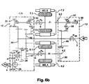
- the figures 6b and 6c respectively show equivalent transmissions according to the invention without Ravigneaux train or with a single epicyclic train.
- the realization without train Ravigneaux implements two electric machines with stator and rotating rotor, whereas the realization with a single epicyclic train implements a conventional electric machine (with fixed stator) and an electric machine with stator and rotating rotor.
- FIG. 6a shows a schematic representation of a conventional transmission device 1 comprising an input shaft 2 intended to be connected to a thermal motor 3 and an output shaft 4 intended to be connected to the wheels 5.
- This device 1 comprises a first electric machine 6 and a second electric machine 7 respectively provided with a shaft 8 and a shaft 9.
- the electrical chain connecting the machines 6 and 7 electric between them is not represented.
- the input and output shafts 2, 4 and the shafts 8 and 9 are interconnected via a mechanical assembly 12 delimited by a discontinuous closed line.
- This mechanical assembly 12 comprises a Ravigneaux-type train resulting from the combination of two trains 14.1 and 14.2 epicyclic.
- the train 14.1, reason R2 comprises a sun gear 17, a planet carrier 19 carrying the satellites 19.1 and a ring 20 which mesh mutually.
- the train 14.2, reason R1 comprises a sun gear 23 and satellites 24 carried by the planet carrier 19. The satellites 24 meshes with the sun gear 23 and the satellites 19.1.
- the train 14. 2 is devoid of crown.
- the input shaft 2 is connected to the planet carrier 19 common to the two trains.
- the output shaft 4 is connected to the ring gear 20 via a bridge drop 25 of ratio ⁇ 1 and a wheel 26.
- the reduction ratio between the ring gear and the wheel 26 is denoted ⁇ 0.
- the shaft 8 is connected to the sun gear 23 via the wheels 29.1 and 29. 2 which form between them a gear 29 of report of gear ratio r1.
- the shaft 9 of the machine 7 may be selectively connected to either the ring 20 or the first sun gear 17 via a wheel 17.1.
- the device 1 comprises a dog clutch C2 which can be associated with an idler gear 31 and a dog clutch C3 that can be associated with an idle gear wheel 32.
- the dogs C2, C3 are rotated by the shaft 9 and are able to move about translation to ensure an angular connection between the shaft 9 and the idler 31,32.
- the idle gear 31 and the ring gear 20 form a reduction ratio gear r2.
- the idler gear 32 and the wheel 17.1 form a reduction ratio gear r3.
- the speed Wa of the machine 6 depends on the engine speeds Wmth and Wsort wheels.
- the speed Wb of the machine 7 is proportional to the speed Wsort of the wheels.
- the dog clutch C3 cooperates with the pinion 32. While the clutch C2 is disengaged from the pinion 31 and therefore does not transmit mechanical torque.
- the mode change is performed when the shaft 9 and the pinions 31 and 32 have substantially the same speed of rotation.
- a transmission device 1.1 represented in FIG. figure 6b .
- This device 1.1 devoid of epicyclic trains corresponds to the realization of the figure 4a .
- the sizing of the electrical machines 6, 7 is identical to that of the transmission of the figure 6a .
- the ratios ⁇ 0, ⁇ 1, r2 as well as the positioning of the shafts 8, 9 and claws C2, C3 are retained.
- the device 1.1 comprises a first electrical machine 6 provided with a rotor 6.1 and a stator 6.2 rotating and a second electric machine 7 provided with a rotor 7.1 and a stator 7.2 rotating.
- the input shafts 2 and 4 as well as the shafts of the electrical machines 6, 7 are interconnected by means of a mechanical assembly 12 formed by a plurality of single gear wheels.
- the output shaft 4 is connected to a tree intermediate 4.1 via a bridge descent 25 report ⁇ 1, this intermediate shaft 4.1 itself being connected to the input shaft 2 via a gear ratio ⁇ 0 formed by the wheels 44 and 26.
- the reports ⁇ 0 and ⁇ 1 are identical to those of the figure 6a .
- the shaft 8 of the rotor of the machine 6 is connected to the wheel 45 via a wheel 47, the gear ratio between these two wheels being noted q1.
- the shaft 8.2 of the stator of the machine 6 is connected to the input shaft 2 via a ratio gear q2 formed by the wheels 49 and 50.
- the shaft 9 of the rotor of the machine 7 can be selectively connected to the shaft 2 via a gear ratio r2 formed by the wheels 31 and 44 or via a gear q3 ratio formed by the wheels 32, 53 and 45.
- the device 1 comprises a dog clutch C2 associated with the idler gear 31 and a clutch C3 associated with the idler gear 32.
- the shaft 9.2 of the stator 7.2 of the machine 7 can be selectively connected to the housing 55 or to the input shaft 2 via a ratio gear q4 formed by the idler gear 57 and the wheels 49 and 58.
- the device 1 comprises a clutch C5 associable with the frame 55 and a Clutch C4 associated with the idle gear 57.
- the regime Wa of the rotor 6.1 of the machine 6 depends on the speed of the input and output shafts 4; and the speed Wb of the rotor 7.1 the machine 7 is proportional to that of the output shaft 4 (vehicle wheels).
- the coupled output mode observable during the mode change with C3 and C5 engaged and C2, C4 disengaged could be used independently of other modes in particular vehicle life phases such as take-offs (phases in which the vehicle goes from zero speed to non-zero speed), or hill starts.
- the dimensioning of the electrical machines 6, 7 is identical to that of the transmission represented in FIG. figure 6a .
- the multiplications ⁇ 0, ⁇ 1, r2 and r3 as well as the positioning of the shafts 2, 4, 8 and 9 and jaws C2, C3 are retained.
- the device 1.1 comprises a first electrical machine 6 provided with a rotating rotor 6.1 and a stator 6.2 as well as a second electric machine 7 with a rotating rotor 7.1 and a fixed stator 7.2.
- the input shafts 2 and 4 as well as the shafts of the machines 6, 7 are interconnected by means of a mechanical assembly 12 formed by the epicyclic gear train 14.1.
- This train 14. 1 comprises a sun gear 17, a planet carrier 19 carrying the satellites 19.1 and a ring 20 which mesh mutually.
- the input shaft 2 is connected to the sun gear 19.
- the output shaft 4 is connected to an intermediate shaft 4.1 via the bridge descent 25 of report ⁇ 1.
- This intermediate shaft 4.1 is itself connected to the ring 20 via a wheel 26.
- the ring 20 and the wheel 26 have between them a gear ratio ⁇ 0.
- the ratios ⁇ 0 and ⁇ 1 are identical to those of the figure 6a .
- the shaft 8 of the rotor of the machine 6 is connected to the sun gear 17 via a ratio gear q1 formed by the wheels 45 and 47.
- the shaft 8.2 of the stator of the machine 6 is connected to the shaft 2 d input via a ratio gear q2 formed by the wheels 49 and 50.
- the shaft 9 of the rotor of the machine 7 can be selectively connected to the shaft 2 via a gear ratio r2 formed by the wheels 31 and 44 or via a gear q3 ratio formed by the wheels 32, 53 and 45.
- the device 1 comprises a dog clutch C2 associated with the idler gear 31 and a clutch C3 associated with the idler gear 32.
- the shaft 9 of the machine 7 is capable of being selectively connected either to the ring gear 20 or to the first sun gear 17.
- the device 1 comprises a clutch C2 that can be associated with an idle gear 31 and a clutch C3 that can be associated with a crazy gear 32.
- the idle gear 31 and the ring gear 20 form a reduction ratio gear r2.
- the idler gear 32 and the wheel 45 form a reduction ratio gear r3.
- the rotor scheme Wa 6.1 of machine 6 depends on the speed of the input and output shafts 2; and the speed Wb of the machine 7 is proportional to that of the output shaft 4 (of the vehicle wheels).
- the mode change is performed when the shaft 9 and the pinions 31 and 32 have substantially the same speed of rotation.
- the displacement of the claws is carried out in a conventional manner using forks.
Description
- . La présente invention concerne un dispositif de transmission de puissance entre une sortie d'un moteur thermique et un arbre de roues, ainsi que l'utilisation de ce dispositif. L'invention a notamment pour but de limiter l'encombrement et le coût d'un tel dispositif. L'invention trouve une application particulièrement avantageuse, mais non exclusive, dans le domaine des véhicules automobiles hybrides à dérivation de puissance.
- . Comme représenté à la
figure 1 , un dispositif 1 de transmission à dérivation de puissance comporte un arbre d'entrée 2 relié à une source 3 de puissance mécanique (en général un moteur thermique) et un arbre de sortie 4 relié aux roues 5 du véhicule. Ce dispositif 1 comporte deux machines électriques 6, 7 reliées entre elles par une chaîne électrique 11, et un ensemble mécanique 12 assurant la liaison entre la source 3 de puissance, les roues 5 du véhicule, et les deux machines électriques 6, 7. - . La puissance de la source 3 est soit transmise aux roues 5, soit dérivée vers les machines électriques 6, 7 susceptibles de se comporter en moteur ou en générateur selon des valeurs d'énergies reçues électriquement et/ou mécaniquement respectivement sur leurs bornes et leur arbre. La puissance dérivée est retransmise aux roues 5 du véhicule ou stockée, le cas échéant, dans une batterie connectée à la chaîne électrique.
- . Cette puissance dérivée permet d'adapter précisément le couple appliqué aux roues 5 du véhicule à celui demandé par un conducteur, tout en adaptant également précisément les couple et régime du moteur thermique de façon à optimiser son rendement.
- . La plupart des dispositifs de transmission proposés, tels que ceux décrits dans les demandes de brevet française
FR-A-2832357 FR-2883515
EP 1092 581 montre les caractéristiques du préambule de la revendication 1. - . L'invention se propose de limiter le recours à l'utilisation des trains épicycloïdaux qui sont des éléments mécaniques dont la conception et la réalisation sont complexes.
- . A cet effet, l'invention consiste à remplacer les machines dont le rotor est connecté au train épicycloïdal et le stator au carter de la transmission, par des machines comportant un rotor et un stator tournants connectés à l'entrée et à la sortie de la transmission.
- . Du point de vue fonctionnel, les deux types d'architectures sont identiques. En outre, le dimensionnement fonctionnel des machines électriques pour les transmissions avec et sans train épicycloïdaux est équivalent. Toutefois les démultiplications entre les machines et les arbres d'entrée et de sortie sont de préférence modifiées.
- . L'intérêt de l'invention est d'ordre économique, la suppression d'un ou de plusieurs trains épicycloïdaux dans une transmission à dérivation de puissance permettant de réduire sensiblement le coût de fabrication du dispositif de transmission. En outre, en supprimant au moins un train épicycloïdal de l'ensemble mécanique, on limite son encombrement.
- . L'invention concerne donc un dispositif de transmission de puissance selon la revendication 1.
- . Selon une réalisation, les deux machines électriques étant à stator tournant, l'ensemble mécanique est dépourvu de train épicycloïdal.
- . Selon une des réalisations, une des machines étant à stator tournant et l'autre à stator fixe, l'ensemble mécanique comporte uniquement un train épicycloïdal formé par un planétaire, un porte-satellites portant des satellites et une couronne qui engrènent entre eux.
- . Selon une réalisation, l'arbre d'entrée est lié directement au porte-satellites et l'arbre de sortie est lié à un arbre intermédiaire via une descente de pont de rapport µl, cet arbre intermédiaire étant relié à la couronne via un engrenage de rapport µ0.
- . Selon une réalisation, l'arbre de la machine à stator fixe est susceptible d'être lié sélectivement à la couronne via un engrenage de rapport r2 ou au planétaire via un engrenage de rapport r3.
- . Selon une réalisation, le stator de la machine à stator tournant est lié à l'arbre d'entrée via un engrenage de rapport q2, et le rotor de la machine à stator tournant est relié au planétaire via un engrenage de rapport q1.
- . Selon une réalisation, µ0=-0.15 ; u1=-1.65 ; r2=-0.25 ; r3=-0:89 ; q1=-0.26 ; q2=-0.50.
- . Selon une réalisation, l'arbre de sortie est lié à un arbre intermédiaire via une descente de pont de rapport µ1, cet arbre intermédiaire étant lui-même lié à l'arbre d'entrée via un engrenage de rapport µ0.
- . Selon une réalisation, le rotor de la première machine est lié aux roues via un engrenage de rapport q1, et le stator de cette machine est lié à l'arbre d'entrée via un engrenage de rapport q2.
- . Selon une réalisation, le rotor de la deuxième machine est susceptible d'être lié sélectivement à l'arbre de sortie via un engrenage de rapport r2 ou via un engrenage de rapport q3, respectivement au moyen d'un premier crabot et d'un deuxième crabot, le stator de cette deuxième machine étant susceptible d'être lié sélectivement à l'arbre d'entrée via un engrenage de rapport q4 ou au bâti fixe respectivement au moyen d'un troisième crabot et d'un quatrième crabot.
- . Selon une réalisation, µ0=-0.15 ; µ1=-1.65; r2=-0.25; r3=-0.89 ; q1=-0.26 ; q2=-0.50 ; q3=0.49 ; q4=0.32.
- . L'invention concerne en outre l'utilisation du dispositif selon l'invention, caractérisée en ce que :
- dans un mode de fonctionnement de type sortie couplée, on ferme les premier et quatrième crabots, et on ouvre les deuxième et troisième crabots, et
- dans un mode combiné, on ferme les deuxième et troisième crabots; et on ouvre les premiers et quatrième crabots.
- . Selon une mise en oeuvre, pour passer du mode sortie couplé au mode combiné, on désengage le premier crabot tout en conservant le quatrième crabot engagé, on synchronise le régime du rotor de la deuxième machine avec un pignon fou associable au deuxième crabot, puis on engage ce deuxième crabot, on désengage le quatrième crabot, on synchronise le régime du stator de la machine avec le pignon associable au crabot et on engage le crabot avec ce pignon.
- . Selon une mise en oeuvre, pour passer du mode combiné au mode sortie couplée, on désengage le troisième crabot et on arrête le stator de la deuxième machine de manière à engager le quatrième crabot avec le pignon auquel il est associé, et on ouvre le deuxième crabot, on synchronise le rotor de la deuxième machine avec le pignon associable au premier crabot et on engage le premier crabot avec ce pignon.
- . L'invention sera mieux comprise à la lecture de la description qui suit et à l'examen des figures qui l'accompagnent. Ces figures sont données à titre illustratif mais nullement limitatif de l'invention. Ces figures montrent :
- .
Figure 1 (déjà décrite) : une représentation schématique de l'architecture d'un dispositif de transmission à dérivation de puissance ; - .
Figures 2 : des schémas cinématiques de dispositifs de transmission monomode selon l'état de la technique et de leur équivalent selon l'invention ; - .
Figures 3 : des schémas cinématiques de dispositifs de transmission multimodes selon l'état de la technique ; - .
Figures 4 : des schémas cinématiques de transmissions multimodes selon l'invention équivalentes à celles de lafigure 3 dépourvues de trains épicycloïdaux ; - .
Figures 5 : des schémas cinématiques de transmissions multimodes selon l'invention équivalentes à celles de lafigure 3 comprenant un seul train épicycloïdal ; - .
Figures 6 : des représentations schématiques d'un dispositif de transmission de puissance à trains Ravigneaux et de ses équivalents selon l'invention ; - . Les éléments identiques conservent la même référence d'une figure à l'autre.
- . Les
figures 2 montrent à gauche des représentations cinématiques de dispositifs de transmission de puissance selon l'état de la technique de type monomode qui présentent une seule configuration possible de transmission, soit un seul mode de fonctionnement. - . A droite, les
figures 2 montrent des représentations cinématiques des dispositifs de transmissions selon l'invention équivalentes dans lesquelles les trains épicycloïdaux ont été remplacés par une machine électrique à stator tournant et une démultiplication. - . Plus précisément, la
figure 2a montre à gauche une architecture à sortie couplée dans laquelle les arbres des machines électriques 6, 7 (à stator fixe) sont reliés respectivement au train épicycloïdal 14.1 et à l'arbre 4 de sortie. Cette architecture est dite à sortie couplée car le régime de la machine 7 est directement proportionnel au régime de l'arbre de sortie 4. - . Dans le schéma équivalent selon l'invention représenté à droite, l'ensemble formé par la machine électrique 6 à stator fixe et le train épicycloïdal 14.1 a été remplacé par un ensemble formé par une machine électrique 6 et une démultiplication 16.1.
- . La
figure 2b montre à gauche une architecture classique à entrée couplée dans laquelle les arbres des machines électriques 6 et 7 (à stator fixe) sont reliés respectivement au train épicycloïdal 14.1 et à l'arbre d'entrée 2. Cette architecture est dite à entrée couplée car le régime de la machine 7 est directement proportionnel au régime de l'arbre de sortie 4. - . Dans le schéma équivalent selon l'invention représenté à droite, l'ensemble formé par la machine électrique 6 à stator fixe et le train épicycloïdal 14.1 a été remplacé par un ensemble formé par une machine électrique 6 à stator tournant et une démultiplication 16.1.
- . La
figure 2c montre à gauche une architecture de type combiné dans laquelle les machines électriques 6 et 7 (à stator fixe) sont reliées à l'arbre d'entrée 2 et à l'arbre de sortie 4 chacune via un train épicycloïdal 14.1, 14.2. Cette architecture est dite de type combiné car le régime des machines 6, 7 dépend des régimes des arbres d'entrée 2 et de sortie 4. - . Dans le schéma équivalent selon l'invention représenté à droite, les machines électriques 6 et 7 à stator fixe et les trains épicycloïdaux 14.1, 14.2 ont été remplacés par des machines électrique 6, 7 à stator tournant et une démultiplication 16.1, 16.2 reliés en parallèle.
- . La simplification des architectures monomodes exposées ci-dessus consistant en un remplacement des trains épicycloïdaux par un stator tournant et une démultiplication peut être étendue aux dispositifs de transmission multimodes dans lesquels un arbre de machine est susceptible d'être branché à deux éléments différents de l'ensemble mécanique. De tels systèmes présentent l'intérêt de limiter la puissance dérivée dans la chaîne électrique en permettant à la machine électrique d'être reliée, parmi les deux éléments, à celui qui tourne le moins vite.
- . Les
figures 3 montrent ainsi des schémas cinématiques de transmissions multimodes selon l'état de la technique, dans lesquelles les deux machines électriques 6, 7 à stator fixe, sont reliées entre elles via deux trains épicycloïdaux 14.1, 14.2. Tandis que lesfigures 4 montrent des schémas de transmissions selon l'invention équivalentes à celles desfigures 3 dans lesquelles les trains épicycloïdaux ont été remplacés par des machines 6, 7 à stator et à rotor et des démultiplications branchées en parallèle. - . Plus précisément, la
figure 3a montre un schéma cinématique d'une transmission selon l'état de la technique apte à fonctionner suivant un mode de type sortie couplée et un mode combiné. Dans le mode à sortie couplée, la machine 7, représentée en traits pleins, est connectée directement à l'arbre 4 de sortie, tandis que dans le mode combiné la machine 7, représentée en traits discontinus, est connectée au train épicycloïdal 14.1. - . La
figure 4a représente un schéma cinématique d'une transmission selon l'invention, équivalente, dans laquelle les trains épicycloïdaux 14.1, 14.2 ont été remplacés par deux machines 6, 7 à rotor et à stator tournants et des démultiplications 16.1, 16.2. Dans le mode à sortie couplée, le stator de la machine 7, représentée en traits discontinus, est relié au carter, une démultiplication 16.1a étant reliée en sortie de la machine 7. Dans le mode combiné, le stator de la machine 7, représentée en traits pleins, est relié à l'arbre d'entrée 2, une démultiplication 16.1 b (différente de 16.1a) étant reliée en sortie de la machine 7. Un dispositif de commutation monté sur l'arbre de la machine 7 assure la commutation d'un mode à l'autre. - . La
figure 3b montre un schéma cinématique d'une transmission selon l'état de la technique fonctionnant selon un mode de type entrée couplée et un mode combiné. Dans le mode à entrée couplée, la machine 6 représentée en traits discontinus, est connectée directement à l'arbre 2 d'entrée. Dans le mode combiné, la machine 6 représentée en traits pleins, est connectée au train épicycloïdal 14.2. - . La
figure 4b montre un schéma cinématique d'une transmission selon l'invention, équivalente, dans laquelle les trains épicycloïdaux 14.1, 14.2 ont été remplacés par deux machines 6, 7 à rotor et à stator tournants et des démultiplications 16.1, 16.2. Dans le mode à entrée couplée, le stator de la machine 7, représentée en traits discontinus, est relié au carter, une démultiplication 16.1a étant reliée en sortie de la machine 7. Dans le mode combiné, le stator de la machine 7, représentée en traits pleins, est relié à l'arbre 4 de sortie, une démultiplication 16.1b (différente de 16.1a) étant reliée en sortie de la machine 7. Un dispositif de commutation monté sur l'arbre la machine 7 assure la commutation d'un mode à l'autre. - . La
figure 4c montre un schéma cinématique d'une transmission selon l'invention à entrée et à sortie couplée. Dans le mode à entrée couplée, le stator et le rotor de la machine 7, représentée en traits discontinus, sont reliés respectivement au carter et à l'arbre 2 d'entrée, une démultiplication 16.1a étant reliée en sortie de la machine 7. Dans le mode à sortie couplée, le stator et le rotor de la machine 7 sont reliés respectivement au carter et à l'arbre 4 de sortie, une démultiplication 16.1b (différente de 16.1a) étant reliée en sortie de la machine 7. Un dispositif de commutation monté sur l'arbre de la machine 7 assure la commutation d'un mode l'autre. - . Toutefois, dans le cas de l'utilisation de deux machines 6, 7 à stator tournant, la synchronisation mécanique des éléments de liaison pour passer d'un mode à l'autre n'est plus assurée au moment des changements de mode d'accouplement, une synchronisation de chacun des arbres étant nécessaire avant de changer de mode.
- . Les
figures 5 montrent des schémas de transmission selon l'invention équivalentes à celles desFigures 3 permettant de conserver la propriété de synchronisme de la transmission. A cet effet, on remplace le train épicycloïdal lié à la machine à partir de laquelle aucune reconfiguration mécanique n'est effectuée et on conserve le train épicycloïdal lié à la machine assurant le changement de mode. - . La
figure 5a montre ainsi un schéma cinématique d'une architecture équivalente à celle de lafigure 3a dans laquelle le train épicycloïdal 14.2 lié à la machine 6 n'assurant aucun changement de mode est remplacé par une machine à rotor et à stator tournant et une démultiplication 16.2. Toutefois le train 14.1 lié à la machine 7 assurant le changement de mode est conservé. - . La
figure 5b montre un schéma cinématique d'une architecture équivalente à celle de lafigure 3b dans laquelle le train 14.2 lié à la machine 6, qui n'est pas reconfigurée, est remplacé par une machine 6 à rotor et à stator tournant. Toutefois, le train 14.1 lié à la machine 7 permettant la synchronisation mécanique lors du changement de mode est conservé. - . La
figure 6a montre une représentation schématique d'un dispositif de transmission selon l'état de la technique comportant un train Ravigneaux (résultant de la combinaison de deux trains épicycloïdaux). Lesfigures 6b et6c montrent respectivement les transmissions équivalentes selon l'invention sans train Ravigneaux ou avec un seul train épicycloïdal. - . La réalisation sans train Ravigneaux met en oeuvre deux machines électriques à stator et à rotor tournants, tandis que la réalisation avec un seul train épicycloïdal met en oeuvre une machine électrique classique (à stator fixe) et une machine électrique à stator et à rotor tournants.
- . Plus précisément, la
figure 6a montre une représentation schématique d'un dispositif 1 de transmission classique comprenant un arbre d'entrée 2 destiné à être relié à un moteur 3 thermique et un arbre de sortie 4 destiné à être relié aux roues 5. - . Ce dispositif 1 comporte une première machine 6 électrique et une deuxième machine 7 électriques munies respectivement d'un arbre 8 et d'un arbre 9. Pour plus de simplicité, la chaîne électrique reliant les machines 6 et 7 électriques entre elles n'est pas représentée.
- . Les arbres d'entrée et de sortie 2, 4 ainsi que les arbres 8 et 9 sont reliés entre eux via un ensemble 12 mécanique délimité par une ligne fermée discontinue.
- . Cet ensemble 12 mécanique comporte un train de type Ravigneaux résultant de la combinaison de deux trains 14.1 et 14.2 épicycloïdaux. Le train 14.1, de raison R2, comporte un planétaire 17, un porte-satellites 19 portant les satellites 19.1 et une couronne 20 qui engrènent mutuellement. Le train 14.2, de raison R1, comporte un planétaire 23 et des satellites 24 portés par le porte-satellites 19. Les satellites 24 engrènent avec le planétaire 23 et les satellites 19.1. Le train 14. 2 est dépourvu de couronne.
- . Dans cette réalisation, l'arbre 2 d'entrée est relié au porte-satellites 19 commun aux deux trains. L'arbre 4 de sortie est relié à la couronne 20 par l'intermédiaire d'une descente de pont 25 de rapport µ1 et d'une roue 26. Le rapport de démultiplication entre la couronne et la roue 26 est noté µ0.
- . Par ailleurs, l'arbre 8 est relié au planétaire 23 par l'intermédiaire des roues 29.1 et 29. 2 qui forment entre elles un engrenage 29 de rapport de démultiplication r1.
- . L'arbre 9 de la machine 7 est susceptible d'être lié sélectivement soit à la couronne 20, soit au premier planétaire 17 via une roue 17.1. A cet effet, le dispositif 1 comporte un crabot C2 associable à un pignon fou 31 et un crabot C3 associable à un pignon fou 32. Les crabots C2, C3 sont entraînés en rotation par l'arbre 9, et sont capables de se déplacer en translation afin d'assurer une liaison angulaire entre l'arbre 9 et le pignon fou 31,32.
- . Le pignon fou 31 et la couronne 20 forment un engrenage de rapport de démultiplication r2. Le pignon fou 32 et la roue 17.1 forment un engrenage de rapport de démultiplication r3.
- . Dans un premier mode de fonctionnement de type sortie couplée (SC), le crabot C2 entre en coopération avec le pignon 31, tandis que le crabot C3 est désengagé du pignon 32 et ne transmet donc pas de couple mécanique entre les arbres 9 et 4 en regard.
- . Dans ce mode SC, les régimes Wa, Wb des machines électriques 6 et 7 d'une part, et les régimes Wsort des roues et Wmth du moteur thermique d'autre part sont liés par les équations suivantes :


- . On remarque ainsi que dans le mode SC, le régime Wa de la machine 6 dépend des régimes du moteur thermique Wmth et des roues Wsort. Le régime Wb de la machine 7 est proportionnel au régime Wsort des roues.
- . Dans le deuxième mode de fonctionnement de type combiné, le crabot C3 entre en coopération avec le pignon 32. Tandis que le crabot C2 est désengagé du pignon 31 et ne transmet donc pas de couple mécanique.
- . Dans ce mode, les régimes Wa, Wb des machines électriques 6, 7 d'une part et les régimes Wsort des roues et Wmth du moteur thermique d'autre part sont liés par les équations suivantes :


- . On remarque ainsi que dans le mode combiné, les régimes Wa et Wb des machines 6, 7 dépendent des régimes du moteur thermique Wmth et des roues Wsort.
- . Dans un exemple R1=-2.07 ; R2=1.81 ; r1=-0.54 ; r2=-0.25 ; r3=-0.89 ; µ0=-0.15 ; µ1=-1.65
- . Dans la pratique, le changement de mode est effectué lorsque l'arbre 9 et les pignons 31 et 32 présentent sensiblement la même vitesse de rotation.
- . En assemblant les architectures selon l'invention pour réaliser chacun des différents modes de fonctionnement, on obtient un dispositif de transmission 1.1 représenté à
figure 6b . Ce dispositif 1.1 dépourvu de trains épicycloïdaux correspond à la réalisation de lafigure 4a . - . Le dimensionnement des machines électriques 6, 7 est identique à celui de la transmission de la
figure 6a . En outre, les démultiplications µ0, µ1, r2 ainsi que le positionnement des arbres 8, 9 et des crabots C2, C3 sont conservés. - . Plus précisément, le dispositif 1.1 comporte une première machine électrique 6 munie d'un rotor 6.1 et d'un stator 6.2 tournants ainsi qu'une deuxième machine électrique 7 munie d'un rotor 7.1 et d'un stator 7.2 tournants.
- . Les arbres 2 et 4 d'entrée ainsi que les arbres des machines électriques 6, 7 sont reliés entre eux par l'intermédiaire d'un ensemble mécanique 12 formé par plusieurs roues dentées simples.
- . Plus précisément, l'arbre de sortie 4 est relié à un arbre intermédiaire 4.1 via une descente de pont 25 de rapport µ1, cet arbre intermédiaire 4.1 étant lui-même relié à l'arbre d'entrée 2 via un engrenage de rapport µ0 formé par les roues 44 et 26. Les rapports µ0 et µ1 sont identiques à ceux de la
figure 6a . - . Par ailleurs, l'arbre 8 du rotor de la machine 6 est relié à la roue 45 via une roue 47, le rapport de démultiplication entre ces deux roues étant noté q1. L'arbre 8.2 du stator de la machine 6 est relié à l'arbre 2 d'entrée via un engrenage de rapport q2 formé par les roues 49 et 50.
- . L'arbre 9 du rotor de la machine 7 est susceptible d'être lié sélectivement à l'arbre 2 via un engrenage de rapport r2 formé par les roues 31 et 44 ou via un engrenage de rapport q3 formé par les roues 32, 53 et 45. A cet effet le dispositif 1 comporte un crabot C2 associable au pignon fou 31 et un crabot C3 associable au pignon fou 32.
- . Par ailleurs, l'arbre 9.2 du stator 7.2 de la machine 7 est susceptible d'être lié sélectivement au carter 55 ou à l'arbre d'entrée 2 via un engrenage de rapport q4 formé par le pignon fou 57 et les roues 49 et 58. A cet effet, le dispositif 1 comporte un crabot C5 associable au bâti 55 et un crabot C4 associable au pignon fou 57.
- . En mode SC, les crabots C2 et C5 sont fermés, C3 et C4 ouverts. Les équations en régime Wa, Wb des rotors des machines 6, 7 s'écrivent alors :


- . Dans ce mode, le régime Wa du rotor 6.1 de la machine 6 dépend du régime des arbres d'entrée 2 et de sortie 4 ; et le régime Wb du rotor 7.1 la machine 7 est proportionnel à celui de l'arbre de sortie 4 (des roues du véhicules).
- . En mode combiné, les crabots C3 et C4 entrent en coopération respectivement avec les pignons 32, 57 ; et les crabots C2 et C5 sont désengagés respectivement des pignons 31 et 55. Les équations en régime Wa, Wb des rotors des machines 6, 7 s'écrivent alors :


- . Dans ce mode, les régimes des machines 6, 7 dépendent des régimes des arbres d'entrée 2 et de sortie 4.
- . On peut calculer les nouvelles démultiplications q1 à q4 par identification avec les équations (1) à (4) :


D'après les valeurs r1, r3, R1, R2 indiquées précédemment, q1=-0.26 ; q2=-0.50 ; q3=0.49 ; q4=0.32. - . Lors de la transition entre les deux modes de fonctionnement de l'architecture de la
figure 6 , on effectue la synchronisation du rotor et du stator de la machine 7. Cette synchronisation est effectuée par un pilotage approprié du couple électrique de cette machine 7. - . Ainsi pour passer du mode sortie couplé au mode combiné, on peut par exemple désengager le crabot C2 tout en conservant le crabot C5 engagé, de sorte que le rotor de la machine 7 est libre. On synchronise alors le régime du rotor de la machine 7 avec le pignon 32 associé au crabot C3, puis on engage le crabot C3. Ensuite, on désengage le crabot C5, on synchronise le régime du stator de la machine 7 avec le pignon 57 et on engage le crabot C4 avec le pignon 57.
- . De manière inverse, pour passer du mode combiné au mode sortie couplée, on peut par exemple désengager le crabot C4 et ralentir le stator 9.2. Une fois le stator 9.2 arrêté, on engage le crabot C5 avec le pignon 55. Puis on ouvre le crabot C3, on synchronise le régime du rotor 7.1 avec le pignon 31 et on engage le crabot C2 avec le pignon 31.
- . Il est à noter que le mode sortie couplée observable lors du changement de mode avec C3 et C5 engagés et C2, C4 désengagés pourrait être utilisé indépendamment des autre modes dans des phases de vie particulières du véhicule telles que des décollages (phases dans lesquelles le véhicule passe d'une vitesse nulle à une vitesse non nulle), ou des démarrages en côte.
- . Par ailleurs, un autre mode de fonctionnement combiné avec les crabots C2 et C4 engagés et les crabots C3 et C5 désengagés peut être utilisé. Ce mode de fonctionnement peut être mis en oeuvre pour optimiser les points de fonctionnement des machines électriques dans certaines situations de vie, dépendantes de la technologie de machine utilisée ayant une influence sur les zones de meilleur rendement.
- . Afin de conserver la propriété de synchronisme mécanique de la machine 7 lors de la transition entre les deux modes, on met en oeuvre la cinématique représentée à la
figure 6c dans laquelle la transmission ne comporte qu'un train épicycloïdal simple au lieu du train épicycloïdal double de type Ravigneaux. - . Le dimensionnement des machines électriques 6, 7 est identique à celui de la transmission représentée en
figure 6a . Les démultiplications µ0, µ1, r2 et r3 ainsi que le positionnement des arbres 2, 4, 8 et 9 et des crabots C2, C3 sont conservés. - . Plus précisément, le dispositif 1.1 comporte une première machine électrique 6 munie d'un rotor 6.1 et d'un stator 6.2 tournants ainsi qu'une deuxième machine électrique 7 à rotor 7.1 tournant et à stator 7.2 fixe.
- . Les arbres 2 et 4 d'entrée ainsi que les arbres des machines 6, 7 sont reliés entre eux par l'intermédiaire d'un ensemble mécanique 12 formé par le train épicycloïdal 14.1. Ce train 14. 1, de raison R2, comporte un planétaire 17, un porte-satellites 19 portant les satellites 19.1 et une couronne 20 qui engrènent mutuellement.
- . Dans cette réalisation, l'arbre d'entrée 2 est relié au planétaire 19. L'arbre de sortie 4 est relié à un arbre intermédiaire 4.1 via la descente de pont 25 de rapport µ1. Cet arbre intermédiaire 4.1 est lui-même relié à la couronne 20 via une roue 26. La couronne 20 et la roue 26 présentent entre eux un rapport de démultiplication µ0. Les rapports µ0 et µ1 sont identiques à ceux de la
figure 6a . - . Par ailleurs, l'arbre 8 du rotor de la machine 6 est relié au planétaire 17 via un engrenage de rapport q1 formé par les roues 45 et 47. L'arbre 8.2 du stator de la machine 6 est relié à l'arbre 2 d'entrée via un engrenage de rapport q2 formé par les roues 49 et 50.
- . L'arbre 9 du rotor de la machine 7 est susceptible d'être lié sélectivement à l'arbre 2 via un engrenage de rapport r2 formé par les roues 31 et 44 ou via un engrenage de rapport q3 formé par les roues 32, 53 et 45. A cet effet, le dispositif 1 comporte un crabot C2 associable au pignon fou 31 et un crabot C3 associable au pignon fou 32.
- . L'arbre 9 de la machine 7 est susceptible d'être lié sélectivement soit à la couronne 20, soit au premier planétaire 17. A cet effet, le dispositif 1 comporte un crabot C2 associable à un pignon fou 31 et un crabot C3 associable à un pignon fou 32.
- . Le pignon fou 31 et la couronne 20 forment un engrenage de rapport de démultiplication r2. Le pignon fou 32 et la roue 45 forment un engrenage de rapport de démultiplication r3.
- . Dans le mode de fonctionnement de type sortie couplée (SC), le crabot C2 entre en coopération avec le pignon 31, tandis que le crabot C3 est désengagé du pignon 32. Les équations en régime Wa, Wb des rotors des machines 6, 7 s'écrivent alors :


- . Dans ce mode, le régime Wa du rotor 6.1 de la machine 6 dépend du régime des arbres d'entrée 2 et de sortie 4 ; et le régime Wb de la machine 7 est proportionnel à celui de l'arbre de sortie 4 (des roues du véhicules).
- . En mode combiné, le crabot C3 entre en coopération avec le pignon 32, tandis que le crabot C2 est désengagé du pignon 31. Les équations en régime Wa, Wb des rotors des machines 6, 7 s'écrivent alors :


- . Dans ce mode, les régimes des rotors des machines 6, 7 dépendent des régimes des arbres d'entrée 2 et de sortie 4.
- . Les démultiplications q1 et q2 sont identiques à celles calculées précédemment et valent respectivement :


D'après les valeurs r1 et R1 indiquées précédemment, q1=-0.26 et q2=-0.50. - . Comme pour l'architecture de la
figure 6a , le changement de mode est effectué lorsque l'arbre 9 et les pignons 31 et 32 présentent sensiblement la même vitesse de rotation. - . Le déplacement des crabots est effectué de manière classique à l'aide de fourchettes.
Claims (14)
- Dispositif (1.1) de transmission de puissance comprenant un arbre (2) d'entrée destiné à être relié à un moteur (3) thermique et un arbre (4) de sortie destiné à être relié à un arbre de roues (5), ce dispositif (1.1) comportant en outre :- une première et une deuxième machines électriques (6, 7) comportant respectivement un stator (6.2, 7.2) et un rotor (6.1, 7.1), chaque machine (6,7) étant munie respectivement d'un arbre (8, 9), et- un ensemble mécanique (12) assurant la liaison mécanique entre l'arbre d'entrée (2), l'arbre de sortie (4) et les arbres (8, 9) des machines (6, 7),- au moins une des machines électriques (6, 7) comportant un rotor (6.1) et un stator (6.2) tournants reliés à l'ensemble mécanique (12) et le dispositif comportant en outre- un dispositif de commutation (C2, C3, C4, C5) monté sur l'arbre d'une des machines électriques, ce dispositif de commutation (C2, C3, C4, C5) permettant de lier sélectivement l'arbre (8, 9) de la machine (6, 7) à deux éléments différents de l'ensemble mécanique (12) pour assurer un changement de mode de fonctionnement du dispositif de transmission de puissance,caractérisé en ce que :- le régime de la machine électrique (6, 7) portant le dispositif de commutation est proportionnel exclusivement au régime des roues (5) ou du moteur (3) lorsque l'arbre de ladite machine (6, 7) est lié à un des deux éléments de l'ensemble mécanique (12), et- le régime de la machine électrique (6, 7) portant le dispositif de commutation dépend du régime des roues (5) et du moteur (3) lorsque l'arbre de la machine (6, 7) est lié à l'autre élément de l'ensemble mécanique (12).
- Dispositif selon la revendication 1, caractérisé en ce que les deux machines (6, 7) électriques étant à stator tournant, l'ensemble mécanique (12) est dépourvu de train épicycloïdal.
- Dispositif selon la revendication 1, caractérisé en ce que une des machines (6) étant à stator tournant et l'autre (7) à stator fixe, l'ensemble mécanique (12) comporte uniquement un train épicycloïdal (14.1) formé par un planétaire (17), un porte-satellites (19) portant des satellites (19.1) et une couronne (20) qui engrènent entre eux.
- Dispositif selon la revendication 3, caractérisé en ce que l'arbre d'entrée (2) est lié directement au porte-satellites (19) et l'arbre de sortie (4) est lié à un arbre intermédiaire (4.1) via une descente de pont (25) de rapport µ1, cet arbre intermédiaire (4.1) étant relié à la couronne (20) via un engrenage de rapport µ0.
- Dispositif selon la revendication 3 ou 4, caractérisé en ce que l'arbre (9) de la machine (7) à stator fixe est susceptible d'être lié sélectivement à la couronne (20) via un engrenage de rapport r2 ou au planétaire (17) via un engrenage de rapport r3.
- Dispositif selon l'une des revendications 3 à 5, caractérisé en ce que le stator (6.2) de la machine (6) à stator tournant est lié à l'arbre d'entrée (2) via un engrenage de rapport q2, et le rotor (6.1) de la machine à stator tournant est relié au planétaire (17) via un engrenage de rapport q1.
- Dispositif selon les revendications 4, 5 et 6, caractérisé en ce que µ0=-0.15 ; µ1=-1.65 ; r2=-0.25 ; r3=-0.89 ; q1=-0.26 ; q2=-0.50.
- Dispositif selon la revendication 2, caractérisé en ce que l'arbre de sortie (4) est lié à un arbre intermédiaire (4.1) via une descente de pont (25) de rapport µ1, cet arbre intermédiaire (4.1) étant lui-même lié à l'arbre d'entrée (2) via un engrenage de rapport µ0.
- Dispositif selon la revendication 2 ou 8, caractérisé en ce que le rotor de la première machine (6) est lié aux roues (5) via un engrenage de rapport q1, et le stator de cette machine (6) est lié à l'arbre 2 d'entrée via un engrenage de rapport q2.
- Dispositif selon l'une des revendications 2, 8 ou 9, caractérisé en ce que le rotor de la deuxième machine (7) est susceptible d'être lié sélectivement à l'arbre de sortie (4) via un engrenage de rapport r2 ou via un engrenage de rapport q3, respectivement au moyen d'un premier crabot (C2) et d'un deuxième crabot (C3), et- le stator de cette deuxième machine (7) étant susceptible d'être lié sélectivement à l'arbre d'entrée (2) via un engrenage de rapport q4 ou au bâti fixe (55) respectivement au moyen d'un troisième crabot (C4) et d'un quatrième crabot (C5).
- Dispositif selon les revendications 2, 8, 9 et 10, caractérisé en ce que µ0=-0.15 ; µ1=-1.65 ; r2=-0.25 ; r3=-0.89 ; q1=-0.26 ; q2=-0.50 ; q3=0.49 ; q4=0.32.
- Utilisation du dispositif selon la revendication 10, caractérisée en ce que :- dans un mode de fonctionnement de type sortie couplée, on ferme les premier (C2) et quatrième (C5) crabots, et on ouvre les deuxième (C3) et troisième (C4) crabots, et- dans un mode combiné, on ferme les deuxième (C3) et troisième (C4) crabots; et on ouvre les premiers (C2) et quatrième (C5) crabots.
- Utilisation selon la revendication 12, caractérisée en ce que pour passer du mode sortie couplé au mode combiné, on désengage le premier crabot (C2) tout en conservant le quatrième crabot (C5) engagé, on synchronise le régime du rotor de la deuxième machine (7) avec un pignon fou (32) associable au deuxième crabot (C3), puis on engage ce deuxième crabot (C3), on désengage le quatrième crabot (C5), on synchronise le régime du stator de la machine (7) avec le pignon (57) associable au crabot (C4) et on engage le crabot (C4) avec ce pignon (57).
- Utilisation selon la revendication 12 ou 13, caractérisée en ce que pour passer du mode combiné au mode sortie couplée, on désengage le troisième crabot (C4) et on arrête le stator de la deuxième machine (7) de manière à engager le quatrième crabot (C5) avec le pignon (55) auquel il est associé, et on ouvre le deuxième crabot (C3), on synchronise le rotor de la deuxième machine (7) avec le pignon (31) associable au premier crabot (C2) et on engage le premier crabot (C2) avec ce pignon (31).
Applications Claiming Priority (2)
| Application Number | Priority Date | Filing Date | Title |
|---|---|---|---|
| FR0758834A FR2923185B1 (fr) | 2007-11-07 | 2007-11-07 | Dispositif de transmission de puissance entre une sortie d'un moteur thermique et un arbre de roues et utilisation de ce dispositif |
| PCT/FR2008/052012 WO2009068796A1 (fr) | 2007-11-07 | 2008-11-07 | Dispositif de transmission de puissance entre une sortie d'un moteur thermique et un arbre de roues et utilisation de ce dispositif |
Publications (2)
| Publication Number | Publication Date |
|---|---|
| EP2209660A1 EP2209660A1 (fr) | 2010-07-28 |
| EP2209660B1 true EP2209660B1 (fr) | 2012-10-10 |
Family
ID=39432974
Family Applications (1)
| Application Number | Title | Priority Date | Filing Date |
|---|---|---|---|
| EP08855726A Not-in-force EP2209660B1 (fr) | 2007-11-07 | 2008-11-07 | Dispositif de transmission de puissance entre une sortie d'un moteur thermique et un arbre de roues et utilisation de ce dispositif |
Country Status (5)
| Country | Link |
|---|---|
| US (1) | US8287413B2 (fr) |
| EP (1) | EP2209660B1 (fr) |
| FR (1) | FR2923185B1 (fr) |
| RU (1) | RU2484984C2 (fr) |
| WO (1) | WO2009068796A1 (fr) |
Families Citing this family (8)
| Publication number | Priority date | Publication date | Assignee | Title |
|---|---|---|---|---|
| GB2466975B (en) * | 2009-01-16 | 2013-06-19 | Gm Global Tech Operations Inc | Torque distributing drive mechanism for motorized vehicles |
| US8784257B2 (en) | 2010-05-06 | 2014-07-22 | Volvo Construction Equipment Ab | Continuously variable transmission and a working machine |
| US9994098B2 (en) * | 2015-12-23 | 2018-06-12 | Xiaolin Ai | Multimode electromechanical variable speed transmission apparatus with smooth mode shifting and method of controlling the same |
| FR3048047B1 (fr) * | 2016-02-19 | 2018-03-09 | Renault S.A.S | Procede de controle du decrabotage d'un baladeur |
| US10788104B2 (en) * | 2016-07-26 | 2020-09-29 | Voith Patent Gmbh | Drive apparatus with superposition gearbox |
| US10308104B2 (en) * | 2017-01-13 | 2019-06-04 | Ford Global Technologies, Llc | HyBrid transaxle |
| DE202018100711U1 (de) * | 2018-02-09 | 2018-02-15 | Voith Patent Gmbh | Antriebsvorrichtung mit Drehzahllimitierung |
| US10744865B2 (en) | 2018-10-09 | 2020-08-18 | Ford Global Technologies, Llc | Hybrid transaxle |
Family Cites Families (13)
| Publication number | Priority date | Publication date | Assignee | Title |
|---|---|---|---|---|
| DE59905424D1 (de) * | 1998-03-27 | 2003-06-12 | Bosch Gmbh Robert | Antriebsstrang für ein kraftfahrzeug |
| JP3412544B2 (ja) * | 1999-02-04 | 2003-06-03 | トヨタ自動車株式会社 | 動力出力装置およびその制御方法 |
| FR2799418B1 (fr) * | 1999-10-11 | 2001-12-14 | Renault | Groupe motopropulseur d'un vehicule hybride a coupleur electromagnetique |
| US6656082B1 (en) * | 1999-10-12 | 2003-12-02 | Toyota Jidosha Kabushiki Kaisha | Hybrid vehicle and method of controlling the same |
| DE10146386A1 (de) * | 2001-09-20 | 2003-04-17 | Gkn Automotive Gmbh | Antriebseinheit |
| FR2832357B1 (fr) * | 2001-11-21 | 2004-02-27 | Peugeot Citroen Automobiles Sa | Dispositif de transmission de puissance a au moins deux trains epicycloidaux |
| FR2834248B1 (fr) * | 2001-12-28 | 2005-06-24 | Renault | Dispositif de traction hybride parallele, et procedes de commande de ce dispositif |
| FR2834938B1 (fr) * | 2002-01-23 | 2004-06-04 | Renault | Groupe motopropulseur pour vehicule a transmission electrique hybride |
| RU2264307C2 (ru) * | 2003-10-01 | 2005-11-20 | Никишин Сергей Владимирович | Гибридный силовой агрегат |
| FR2883515B1 (fr) * | 2005-03-23 | 2008-10-31 | Peugeot Citroen Automobiles Sa | Dispositif de transmission de puissance entre une sortie d'un moteur thermique et un arbre de roues et procede de transmission de puissance associe |
| US7479081B2 (en) * | 2006-10-25 | 2009-01-20 | Gm Global Technology Operations | Hybrid electrically variable transmission with dual power paths and selective motor connection |
| ITMI20070528A1 (it) * | 2007-03-16 | 2008-09-17 | Piaggio & C Spa | Sistema di propulsione e di trasmissione ibrida per motoveicoli |
| US7980980B2 (en) * | 2007-11-14 | 2011-07-19 | GM Global Technology Operations LLC | Hybrid powertrain |
-
2007
- 2007-11-07 FR FR0758834A patent/FR2923185B1/fr not_active Expired - Fee Related
-
2008
- 2008-11-07 US US12/738,981 patent/US8287413B2/en active Active
- 2008-11-07 RU RU2010123019/11A patent/RU2484984C2/ru not_active IP Right Cessation
- 2008-11-07 EP EP08855726A patent/EP2209660B1/fr not_active Not-in-force
- 2008-11-07 WO PCT/FR2008/052012 patent/WO2009068796A1/fr active Application Filing
Also Published As
| Publication number | Publication date |
|---|---|
| US8287413B2 (en) | 2012-10-16 |
| FR2923185A1 (fr) | 2009-05-08 |
| RU2010123019A (ru) | 2011-12-20 |
| WO2009068796A1 (fr) | 2009-06-04 |
| EP2209660A1 (fr) | 2010-07-28 |
| FR2923185B1 (fr) | 2010-04-02 |
| US20100320017A1 (en) | 2010-12-23 |
| RU2484984C2 (ru) | 2013-06-20 |
Similar Documents
| Publication | Publication Date | Title |
|---|---|---|
| EP2209660B1 (fr) | Dispositif de transmission de puissance entre une sortie d'un moteur thermique et un arbre de roues et utilisation de ce dispositif | |
| EP1453694B9 (fr) | Dispositif de transmission de puissance a au moins deux trains epicycloïdaux | |
| EP2694309B1 (fr) | Transmission hybride pour vehicule automobile et procede de commande | |
| EP1877273B1 (fr) | Dispositif de commutation pour vehicule automobile et utilisation de ce dispositif | |
| EP2001719B1 (fr) | Procede de transmission de puissance | |
| WO2016092184A1 (fr) | Transmission automatique pour véhicule hybride et procédé de commande d'un véhicule hybride | |
| FR2835301A1 (fr) | Boite de vitesses a arbre intermediaire pour vehicules automobiles | |
| FR2976526A1 (fr) | Groupe motopropulseur | |
| FR2946291A1 (fr) | Groupe motopropulseur pour vehicule electrique a deux arbres permettant d'obtenir deux rapports de transmission | |
| WO2012042137A1 (fr) | Groupe motopropulseur hybride a arbres d'entree coaxiaux et procede de commande correspondant | |
| FR3100755A1 (fr) | Chaîne de transmission électrique pour véhicule automobile | |
| EP1916141B1 (fr) | Système d'entrainement en déplacement pour véhicule hybride | |
| FR2946293A1 (fr) | Groupe motopropulseur pour vehicule electrique a trois arbres permettant d'obtenir deux rapports de transmission | |
| FR3021592A1 (fr) | Transmission automatique pour vehicule hybride | |
| EP1789722B1 (fr) | Dispositif de transmission de puissance pour vehicule automobile et procede d'utilisation de ce dispositif | |
| WO2011055050A1 (fr) | Groupe motopropulseur hybride multirapports a deux machines electriques | |
| WO2004106774A1 (fr) | Boite de vitesses a deux embrayages et a deux arbres secondaires | |
| FR3098766A1 (fr) | Transmission automatique pour véhicule hybride thermique/électrique | |
| FR3077536A1 (fr) | Dispositif de transmission a deux vitesses pour vehicule electrique | |
| FR3029854A1 (fr) | Groupe motopropulseur pour l'entrainement d'un vehicule automobile avec un dispositif de transmission a variation de vitesse a double train epicycloidal et en particulier groupe motopropulseur pour un vehicule de type hybride. | |
| FR2967620A1 (fr) | Vehicule hybride a deux trains d'engrenages epicycloidaux a derivation de puissance et a efficacite energetique amelioree | |
| FR3106089A1 (fr) | Transmission automatique pour véhicule hybride thermique/électrique | |
| FR3106090A1 (fr) | Transmission pour véhicule hybride et son procédé de commande | |
| WO2022084593A1 (fr) | Boite de vitesses comprenant une machine electrique motrice | |
| EP3083301A1 (fr) | Système électromécanique de récupération d'énergie cinétique |
Legal Events
| Date | Code | Title | Description |
|---|---|---|---|
| PUAI | Public reference made under article 153(3) epc to a published international application that has entered the european phase |
Free format text: ORIGINAL CODE: 0009012 |
|
| 17P | Request for examination filed |
Effective date: 20100319 |
|
| AK | Designated contracting states |
Kind code of ref document: A1 Designated state(s): AT BE BG CH CY CZ DE DK EE ES FI FR GB GR HR HU IE IS IT LI LT LU LV MC MT NL NO PL PT RO SE SI SK TR |
|
| AX | Request for extension of the european patent |
Extension state: AL BA MK RS |
|
| DAX | Request for extension of the european patent (deleted) | ||
| 17Q | First examination report despatched |
Effective date: 20110708 |
|
| GRAP | Despatch of communication of intention to grant a patent |
Free format text: ORIGINAL CODE: EPIDOSNIGR1 |
|
| GRAS | Grant fee paid |
Free format text: ORIGINAL CODE: EPIDOSNIGR3 |
|
| GRAA | (expected) grant |
Free format text: ORIGINAL CODE: 0009210 |
|
| AK | Designated contracting states |
Kind code of ref document: B1 Designated state(s): AT BE BG CH CY CZ DE DK EE ES FI FR GB GR HR HU IE IS IT LI LT LU LV MC MT NL NO PL PT RO SE SI SK TR |
|
| REG | Reference to a national code |
Ref country code: GB Ref legal event code: FG4D Free format text: NOT ENGLISH |
|
| REG | Reference to a national code |
Ref country code: AT Ref legal event code: REF Ref document number: 578782 Country of ref document: AT Kind code of ref document: T Effective date: 20121015 Ref country code: CH Ref legal event code: EP |
|
| REG | Reference to a national code |
Ref country code: IE Ref legal event code: FG4D Free format text: LANGUAGE OF EP DOCUMENT: FRENCH |
|
| REG | Reference to a national code |
Ref country code: DE Ref legal event code: R096 Ref document number: 602008019341 Country of ref document: DE Effective date: 20121206 |
|
| PG25 | Lapsed in a contracting state [announced via postgrant information from national office to epo] |
Ref country code: SI Free format text: LAPSE BECAUSE OF FAILURE TO SUBMIT A TRANSLATION OF THE DESCRIPTION OR TO PAY THE FEE WITHIN THE PRESCRIBED TIME-LIMIT Effective date: 20121010 |
|
| REG | Reference to a national code |
Ref country code: GB Ref legal event code: 746 Effective date: 20130215 Ref country code: NL Ref legal event code: VDEP Effective date: 20121010 |
|
| REG | Reference to a national code |
Ref country code: AT Ref legal event code: MK05 Ref document number: 578782 Country of ref document: AT Kind code of ref document: T Effective date: 20121010 |
|
| REG | Reference to a national code |
Ref country code: LT Ref legal event code: MG4D |
|
| REG | Reference to a national code |
Ref country code: DE Ref legal event code: R084 Ref document number: 602008019341 Country of ref document: DE Effective date: 20130206 |
|
| PG25 | Lapsed in a contracting state [announced via postgrant information from national office to epo] |
Ref country code: SE Free format text: LAPSE BECAUSE OF FAILURE TO SUBMIT A TRANSLATION OF THE DESCRIPTION OR TO PAY THE FEE WITHIN THE PRESCRIBED TIME-LIMIT Effective date: 20121010 Ref country code: IS Free format text: LAPSE BECAUSE OF FAILURE TO SUBMIT A TRANSLATION OF THE DESCRIPTION OR TO PAY THE FEE WITHIN THE PRESCRIBED TIME-LIMIT Effective date: 20130210 Ref country code: FI Free format text: LAPSE BECAUSE OF FAILURE TO SUBMIT A TRANSLATION OF THE DESCRIPTION OR TO PAY THE FEE WITHIN THE PRESCRIBED TIME-LIMIT Effective date: 20121010 Ref country code: ES Free format text: LAPSE BECAUSE OF FAILURE TO SUBMIT A TRANSLATION OF THE DESCRIPTION OR TO PAY THE FEE WITHIN THE PRESCRIBED TIME-LIMIT Effective date: 20130121 Ref country code: HR Free format text: LAPSE BECAUSE OF FAILURE TO SUBMIT A TRANSLATION OF THE DESCRIPTION OR TO PAY THE FEE WITHIN THE PRESCRIBED TIME-LIMIT Effective date: 20121010 Ref country code: NL Free format text: LAPSE BECAUSE OF FAILURE TO SUBMIT A TRANSLATION OF THE DESCRIPTION OR TO PAY THE FEE WITHIN THE PRESCRIBED TIME-LIMIT Effective date: 20121010 Ref country code: LT Free format text: LAPSE BECAUSE OF FAILURE TO SUBMIT A TRANSLATION OF THE DESCRIPTION OR TO PAY THE FEE WITHIN THE PRESCRIBED TIME-LIMIT Effective date: 20121010 Ref country code: NO Free format text: LAPSE BECAUSE OF FAILURE TO SUBMIT A TRANSLATION OF THE DESCRIPTION OR TO PAY THE FEE WITHIN THE PRESCRIBED TIME-LIMIT Effective date: 20130110 |
|
| BERE | Be: lapsed |
Owner name: PEUGEOT CITROEN AUTOMOBILES SA Effective date: 20121130 |
|
| PG25 | Lapsed in a contracting state [announced via postgrant information from national office to epo] |
Ref country code: PL Free format text: LAPSE BECAUSE OF FAILURE TO SUBMIT A TRANSLATION OF THE DESCRIPTION OR TO PAY THE FEE WITHIN THE PRESCRIBED TIME-LIMIT Effective date: 20121010 Ref country code: LV Free format text: LAPSE BECAUSE OF FAILURE TO SUBMIT A TRANSLATION OF THE DESCRIPTION OR TO PAY THE FEE WITHIN THE PRESCRIBED TIME-LIMIT Effective date: 20121010 Ref country code: GR Free format text: LAPSE BECAUSE OF FAILURE TO SUBMIT A TRANSLATION OF THE DESCRIPTION OR TO PAY THE FEE WITHIN THE PRESCRIBED TIME-LIMIT Effective date: 20130111 Ref country code: PT Free format text: LAPSE BECAUSE OF FAILURE TO SUBMIT A TRANSLATION OF THE DESCRIPTION OR TO PAY THE FEE WITHIN THE PRESCRIBED TIME-LIMIT Effective date: 20130211 |
|
| PG25 | Lapsed in a contracting state [announced via postgrant information from national office to epo] |
Ref country code: AT Free format text: LAPSE BECAUSE OF FAILURE TO SUBMIT A TRANSLATION OF THE DESCRIPTION OR TO PAY THE FEE WITHIN THE PRESCRIBED TIME-LIMIT Effective date: 20121010 |
|
| REG | Reference to a national code |
Ref country code: CH Ref legal event code: PL |
|
| PG25 | Lapsed in a contracting state [announced via postgrant information from national office to epo] |
Ref country code: BG Free format text: LAPSE BECAUSE OF FAILURE TO SUBMIT A TRANSLATION OF THE DESCRIPTION OR TO PAY THE FEE WITHIN THE PRESCRIBED TIME-LIMIT Effective date: 20130110 Ref country code: SK Free format text: LAPSE BECAUSE OF FAILURE TO SUBMIT A TRANSLATION OF THE DESCRIPTION OR TO PAY THE FEE WITHIN THE PRESCRIBED TIME-LIMIT Effective date: 20121010 Ref country code: LI Free format text: LAPSE BECAUSE OF NON-PAYMENT OF DUE FEES Effective date: 20121130 Ref country code: EE Free format text: LAPSE BECAUSE OF FAILURE TO SUBMIT A TRANSLATION OF THE DESCRIPTION OR TO PAY THE FEE WITHIN THE PRESCRIBED TIME-LIMIT Effective date: 20121010 Ref country code: DK Free format text: LAPSE BECAUSE OF FAILURE TO SUBMIT A TRANSLATION OF THE DESCRIPTION OR TO PAY THE FEE WITHIN THE PRESCRIBED TIME-LIMIT Effective date: 20121010 Ref country code: CZ Free format text: LAPSE BECAUSE OF FAILURE TO SUBMIT A TRANSLATION OF THE DESCRIPTION OR TO PAY THE FEE WITHIN THE PRESCRIBED TIME-LIMIT Effective date: 20121010 Ref country code: CH Free format text: LAPSE BECAUSE OF NON-PAYMENT OF DUE FEES Effective date: 20121130 |
|
| REG | Reference to a national code |
Ref country code: IE Ref legal event code: MM4A |
|
| PLBE | No opposition filed within time limit |
Free format text: ORIGINAL CODE: 0009261 |
|
| STAA | Information on the status of an ep patent application or granted ep patent |
Free format text: STATUS: NO OPPOSITION FILED WITHIN TIME LIMIT |
|
| PG25 | Lapsed in a contracting state [announced via postgrant information from national office to epo] |
Ref country code: RO Free format text: LAPSE BECAUSE OF FAILURE TO SUBMIT A TRANSLATION OF THE DESCRIPTION OR TO PAY THE FEE WITHIN THE PRESCRIBED TIME-LIMIT Effective date: 20121010 Ref country code: BE Free format text: LAPSE BECAUSE OF NON-PAYMENT OF DUE FEES Effective date: 20121130 Ref country code: IT Free format text: LAPSE BECAUSE OF FAILURE TO SUBMIT A TRANSLATION OF THE DESCRIPTION OR TO PAY THE FEE WITHIN THE PRESCRIBED TIME-LIMIT Effective date: 20121010 |
|
| 26N | No opposition filed |
Effective date: 20130711 |
|
| PG25 | Lapsed in a contracting state [announced via postgrant information from national office to epo] |
Ref country code: IE Free format text: LAPSE BECAUSE OF NON-PAYMENT OF DUE FEES Effective date: 20121107 |
|
| REG | Reference to a national code |
Ref country code: DE Ref legal event code: R097 Ref document number: 602008019341 Country of ref document: DE Effective date: 20130711 |
|
| PG25 | Lapsed in a contracting state [announced via postgrant information from national office to epo] |
Ref country code: CY Free format text: LAPSE BECAUSE OF FAILURE TO SUBMIT A TRANSLATION OF THE DESCRIPTION OR TO PAY THE FEE WITHIN THE PRESCRIBED TIME-LIMIT Effective date: 20121010 Ref country code: MT Free format text: LAPSE BECAUSE OF FAILURE TO SUBMIT A TRANSLATION OF THE DESCRIPTION OR TO PAY THE FEE WITHIN THE PRESCRIBED TIME-LIMIT Effective date: 20121010 |
|
| PG25 | Lapsed in a contracting state [announced via postgrant information from national office to epo] |
Ref country code: MC Free format text: LAPSE BECAUSE OF NON-PAYMENT OF DUE FEES Effective date: 20121130 Ref country code: TR Free format text: LAPSE BECAUSE OF FAILURE TO SUBMIT A TRANSLATION OF THE DESCRIPTION OR TO PAY THE FEE WITHIN THE PRESCRIBED TIME-LIMIT Effective date: 20121010 |
|
| PG25 | Lapsed in a contracting state [announced via postgrant information from national office to epo] |
Ref country code: LU Free format text: LAPSE BECAUSE OF NON-PAYMENT OF DUE FEES Effective date: 20121107 |
|
| PG25 | Lapsed in a contracting state [announced via postgrant information from national office to epo] |
Ref country code: HU Free format text: LAPSE BECAUSE OF FAILURE TO SUBMIT A TRANSLATION OF THE DESCRIPTION OR TO PAY THE FEE WITHIN THE PRESCRIBED TIME-LIMIT Effective date: 20081107 |
|
| REG | Reference to a national code |
Ref country code: FR Ref legal event code: PLFP Year of fee payment: 8 |
|
| PGFP | Annual fee paid to national office [announced via postgrant information from national office to epo] |
Ref country code: GB Payment date: 20151027 Year of fee payment: 8 Ref country code: DE Payment date: 20151022 Year of fee payment: 8 |
|
| PGFP | Annual fee paid to national office [announced via postgrant information from national office to epo] |
Ref country code: FR Payment date: 20151023 Year of fee payment: 8 |
|
| REG | Reference to a national code |
Ref country code: DE Ref legal event code: R119 Ref document number: 602008019341 Country of ref document: DE |
|
| GBPC | Gb: european patent ceased through non-payment of renewal fee |
Effective date: 20161107 |
|
| REG | Reference to a national code |
Ref country code: FR Ref legal event code: ST Effective date: 20170731 |
|
| PG25 | Lapsed in a contracting state [announced via postgrant information from national office to epo] |
Ref country code: FR Free format text: LAPSE BECAUSE OF NON-PAYMENT OF DUE FEES Effective date: 20161130 |
|
| PG25 | Lapsed in a contracting state [announced via postgrant information from national office to epo] |
Ref country code: DE Free format text: LAPSE BECAUSE OF NON-PAYMENT OF DUE FEES Effective date: 20170601 Ref country code: GB Free format text: LAPSE BECAUSE OF NON-PAYMENT OF DUE FEES Effective date: 20161107 |