EP2209057A1 - Servodruckregler eines Gasregelgeräts - Google Patents
Servodruckregler eines Gasregelgeräts Download PDFInfo
- Publication number
- EP2209057A1 EP2209057A1 EP09013834A EP09013834A EP2209057A1 EP 2209057 A1 EP2209057 A1 EP 2209057A1 EP 09013834 A EP09013834 A EP 09013834A EP 09013834 A EP09013834 A EP 09013834A EP 2209057 A1 EP2209057 A1 EP 2209057A1
- Authority
- EP
- European Patent Office
- Prior art keywords
- valve
- pressure regulator
- servo
- servo pressure
- regulator according
- Prior art date
- Legal status (The legal status is an assumption and is not a legal conclusion. Google has not performed a legal analysis and makes no representation as to the accuracy of the status listed.)
- Granted
Links
Images

Classifications
-
- G—PHYSICS
- G05—CONTROLLING; REGULATING
- G05D—SYSTEMS FOR CONTROLLING OR REGULATING NON-ELECTRIC VARIABLES
- G05D16/00—Control of fluid pressure
- G05D16/20—Control of fluid pressure characterised by the use of electric means
- G05D16/2006—Control of fluid pressure characterised by the use of electric means with direct action of electric energy on controlling means
- G05D16/2013—Control of fluid pressure characterised by the use of electric means with direct action of electric energy on controlling means using throttling means as controlling means
- G05D16/202—Control of fluid pressure characterised by the use of electric means with direct action of electric energy on controlling means using throttling means as controlling means actuated by an electric motor
Definitions
- the invention relates to a servo pressure regulator of a gas control device according to the preamble of claim 1.
- a servo pressure regulator for a gas control device which comprises a control diaphragm which delimits two pressure chambers of the servo pressure regulator. At least one spring element cooperates with the control diaphragm of the servo pressure regulator.
- the control diaphragm of the servo pressure regulator is associated with a valve body of a servo valve, which cooperates with a valve seat of the servo valve, depending on the voltage applied to the control diaphragm valve body of the servo valve either lifted from the valve seat with the servo valve open or the same is pressed against the valve seat when the servo valve is closed ,
- the servo pressure regulator comprises an actuator which acts on the control diaphragm via a valve rod, wherein the actuator is a coil and therefore designed as an electromagnetic actuator.
- electromagnetic actuators have a number of disadvantages. So they are characterized by friction effects or hysteresis effects. Furthermore, a supply voltage must be continuously provided in order to keep an electromagnetic actuator in a defined position. In addition, the force provided by the electromagnetic actuator is variable and dependent on an air gap in the actuator. Due to the above disadvantages of electromagnetic actuators, the functionality of servo-pressure regulators with electromagnetic actuators is limited.
- the invention is based on the object to provide a novel servo pressure regulator of a gas control device. This object is achieved by a servo pressure regulator of a gas control device having the features of claim 1.
- the actuator comprises a cam which can be driven in rotation by a motor.
- the servo pressure regulator comprises as an actuator a motor and a cam rotatably driven by the motor.
- a motor with a cam as an actuator has the advantage that when the cam has been rotated by the motor to a certain relative position, no voltage must be provided to hold the actuator in that defined relative position.
- frictional properties or hysteresis properties of such an actuator are improved compared to an electromagnetic actuator.
- the force provided by the actuator, which acts on the valve stem of the servo valve of the servo pressure regulator is independent of the position of the actuator or the engine thereof. Another advantage is that larger adjustment paths can be provided than with electromagnetic actuators. Overall, it is possible to extend the functional spectrum of a servo pressure regulator.
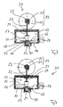
- Fig. 1 shows a first embodiment of a servo pressure regulator 10 according to the invention of a gas control device.
- the servo pressure regulator 10 according to Fig. 1 comprises a housing 11, in which a control diaphragm 12 is positioned, wherein the control diaphragm 12 delimits two pressure chambers 13 and 14 of the servo pressure regulator 10 from each other.
- the control diaphragm 12 is associated with a valve body 15 of a servo valve, wherein the valve body 15 cooperates with a valve seat 16 of the servo valve. Then, when the servo valve is closed, the valve body 15 is pressed against the valve seat 16. Then, when the servo valve is opened, the valve body 15 is lifted from the valve seat 16.
- Fig. 1 interact with the control membrane 12 two spring elements together.
- a first spring element 17 presses from a first side against the control diaphragm 12, namely such that the spring force provided by the first spring element 17 presses the valve body 15 against the valve seat 16 of the servo valve.
- the applied to the control membrane 12 ratio of pressures within the pressure chambers 13, 14 and spring forces of the spring elements 17, 18 ultimately causes whether the servo valve of the servo pressure regulator 10 is open or closed.
- the servo pressure regulator 10 of Fig. 1 has an actuator 19, which comprises a 21 rotatably driven by a motor cam 21.
- the cam 21 acts via a valve rod 22 on the control diaphragm 12, namely indirectly via the first spring element 17.
- the cam 21 has an outer contour 23 which cooperates with the valve rod 22 and depending on their relative rotational position, the valve rod 22 more or less strongly against the first spring element 17 presses. Seen in the direction of rotation or circumferential direction of the cam disc 21, the outer diameter of the outer contour 23 of the cam disk 21 accordingly changes.
- the motor 20 of the actuator 19 is preferably a stepper motor.
- the cam disk 21 can then be rotated into defined rotational positions and thus relative positions to the valve rod 21 via the stepping motor, the cam disk 21, namely the outer contour 23 of the same, having a defined outer diameter in each defined relative position.
- the larger this outer diameter the stronger the valve rod 22 presses against the first spring element 17 and the higher the spring force with which the first spring element 17 presses against the control membrane 12 for closing the servo valve.
- Fig. 1 the two pressure chambers 13 and 14 of the servo pressure regulator 10 are connected to one another via a flow sensor 24.
- a first measuring point of the flow sensor 24 thus acts on the pressure chamber 13 and a second measuring point on the pressure chamber 14.
- the cam 21 is rotatable by means of the motor 20 such that the flow through the flow sensor 24 is approximately zero.
- an accurate 1: 1 control for the ratio of combustion air flow and gas air flow can be established.
- the pressure chamber 13 of the servo pressure regulator 10 is connected via an opening or nozzle 27 with the ambient or a reference pressure, wherein the valve rod 22 is guided in the opening or nozzle 27.
- Fig. 2 shows an embodiment of a servo pressure controller 25, the embodiment of the Fig. 1 such resort that the valve rod 22 is associated with a shut-off element 26 which cooperates with the nozzle 27, via which the pressure chamber 13 of the servo pressure regulator 25 is connected to the environment or a reference pressure.
- a shut-off element 26 which cooperates with the nozzle 27, via which the pressure chamber 13 of the servo pressure regulator 25 is connected to the environment or a reference pressure.
- a gas control device or gas burner with the same a valve-testing system (VPS or Valve Proving System) can be established.
- VPS Valve Proving System
- it can be detected via a measured flow through the flow sensor 24 whether the gas valves, not shown, of the gas control device or gas burner are sealed.
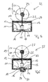
- a third embodiment of a servo pressure regulator 28 according to the invention shows Fig. 3 , wherein the embodiment of the Fig. 3 compared to the embodiment of the Fig. 1 is further developed in that the valve body 15 of the servo valve is connected to a valve body 29 of a turn-on, which cooperates with a corresponding valve seat 30.
- Fig. 4 shows an embodiment of a servo pressure controller 31 according to the invention of the features of the embodiments according to Fig. 2 and 3 combined, so both an integrated on-off valve according to Fig. 3 as well as a shut-off element 26 according to Fig. 2 includes.
- the servo pressure regulator 10, 25, 28 and 31 of the embodiments according to Fig. 1 to 4 are preferably used in so-called premix gas burners in which the gas burner, a defined mixture of gas and combustion air is supplied, without that in the gas burner secondary combustion air is used for the combustion process.
- FIGS. 5 and 6 Embodiments of servo pressure regulators 32 and 33 according to the invention, which find use in so-called atmospheric gas burners, in which the combustion process takes place using secondary combustion air.
- the embodiment corresponds to Fig. 5 the embodiment of the Fig. 1 and the embodiment of the Fig. 6 the embodiment of the Fig. 3 , in each case without a flow sensor 24.
- the embodiments of the FIGS. 5 and 6 can also be used in Vormischgasbrennern used, in which case flow sensors are arranged at a different position, for. B. in the area of a venturi of the gas burner.
- the actuator 19 is preferably associated with a return spring, not shown, which, when the motor 20 is turned off, the cam 21 resets to a home position and so presses the valve body 29 against the valve seat 30 to close the on-valve. In Fig. 4 then also closes the shut-off element 26, the nozzle 27th
- the respective motor 20 must then be turned on or electrically energized to hold the cam 21 in a position deviating from the starting position.
Abstract
Description
- Die Erfindung betrifft einen Servodruckregler eines Gasregelgeräts nach dem Oberbegriff des Anspruchs 1.
- Aus der
EP 0 740 242 B1 ist ein Servodruckregler für ein Gasregelgerät bekannt, welches eine Regelmembran umfasst, die zwei Druckkammern des Servodruckreglers voneinander begrenzt. Mit der Regelmembran des Servodruckreglers wirkt mindestens ein Federelement zusammen. Der Regelmembran des Servodruckreglers ist ein Ventilkörper eines Servoventils zugeordnet, der mit einem Ventilsitz des Servoventils zusammenwirkt, wobei abhängig von der an der Regelmembran anliegenden Druckdifferenz der Ventilkörper des Servoventils entweder bei geöffnetem Servoventil vom Ventilsitz desselben abgehoben oder bei geschlossenem Servoventil gegen den Ventilsitz desselben gedrückt ist. - Nach der
EP 0 740 242 B1 umfasst der Servodruckregler einen Aktuator, der über eine Ventilstange auf die Regelmembran einwirkt, wobei der Aktuator eine Spule und demnach als elektromagnetischer Aktuator ausgebildet ist. Solche elektromagnetischen Aktuatoren verfügen über eine Vielzahl von Nachteilen. So sind dieselben durch Reibeffekte bzw. Hystereseeffekte gekennzeichnet. Weiterhin muss kontinuierlich eine Versorgungsspannung bereitgestellt werden, um einen elektromagnetischen Aktuator in einer definierten Position zu halten. Darüberhinaus ist die vom elektromagnetischen Aktuator bereitgestellte Kraft variabel und abhängig von einem Luftspalt im Aktuator. Aufgrund der obigen Nachteile von elektromagnetischen Aktuatoren ist die Funktionalität von Servodruckreglern mit elektromagnetischen Aktuatoren beschränkt. - Der Erfindung liegt die Aufgabe zu Grunde, einen neuartigen Servodruckregler eines Gasregelgeräts zu schaffen. Diese Aufgabe wird durch einen Servodruckregler eines Gasregelgeräts mit den Merkmalen des Anspruchs 1 gelöst. Erfindungsgemäß umfasst der Aktuator eine von einem Motor drehend antreibbare Kurvenscheibe.
- Der erfindungsgemäße Servodruckregler umfasst als Aktuator einen Motor und eine vom Motor drehend antreibbare Kurvenscheibe. Die Verwendung eines Motors mit einer Kurvenscheibe als Aktuator verfügt über den Vorteil, dass dann, wenn die Kurvenscheibe mithilfe des Motors in eine bestimmte Relativposition gedreht wurde, keine Spannung bereitgestellt werden muss, um den Aktuator in dieser definierten Relativposition zu halten. Darüberhinaus sind Reibeigenschaften oder Hystereseeigenschaften eines solchen Aktuators im Vergleich zu einem elektromagnetischen Aktuator verbessert. Die vom Aktuator bereitgestellte Kraft, die auf die Ventilstange des Servoventils des Servodruckreglers einwirkt, ist unabhängig von der Position des Aktuators bzw. des Motors desselben. Ein weiterer Vorteil liegt darin, dass größere Verstellwege bereitgestellt werden können als mit elektromagnetischen Aktuatoren. Insgesamt ist es möglich, das Funktionsspektrum eines Servodruckreglers zu erweitern.
- Bevorzugte Weiterbildungen der Erfindung ergeben sich aus den Unteransprüchen und der nachfolgenden Beschreibung. Nachfolgend werden Ausführungsbeispiele der Erfindung, ohne hierauf beschränkt zu sein, anhand der Zeichnung näher erläutert. In der Zeichnung zeigt:
- Fig. 1:
- eine schematisierte Darstellung eines erfindungsgemäßen Servodruckreglers eines Gasregelgeräts nach einem ersten Ausführungsbeispiel der Erfindung;
- Fig. 2:
- eine schematisierte Darstellung eines erfindungsgemäßen Servodruckreglers eines Gasregelgeräts nach einem zweiten Ausführungsbeispiel der Erfindung;
- Fig. 3:
- eine schematisierte Darstellung eines erfindungsgemäßen Servodruckreglers eines Gasregelgeräts nach einem dritten Ausführungsbeispiel der Erfindung;
- Fig. 4:
- eine schematisierte Darstellung eines erfindungsgemäßen Servodruckreglers eines Gasregelgeräts nach einem vierten Ausführungsbeispiel der Erfindung;
- Fig. 5:
- eine schematisierte Darstellung eines erfindungsgemäßen Servodruckreglers eines Gasregelgeräts nach einem fünften Ausführungsbeispiel der Erfindung; und
- Fig. 6:
- eine schematisierte Darstellung eines erfindungsgemäßen Servodruckreglers eines Gasregelgeräts nach einem sechsten Ausführungsbeispiel der Erfindung.
-
Fig. 1 zeigt ein erstes Ausführungsbeispiel eines erfindungsgemäßen Servodruckreglers 10 eines Gasregelgeräts. Der Servodruckregler 10 gemäßFig. 1 umfasst ein Gehäuse 11, in dem eine Regelmembran 12 positioniert ist, wobei die Regelmembran 12 zwei Druckkammern 13 und 14 des Servodruckreglers 10 voneinander abgrenzt. - Der Regelmembran 12 ist ein Ventilkörper 15 eines Servoventils zugeordnet, wobei der Ventilkörper 15 mit einem Ventilsitz 16 des Servoventils zusammenwirkt. Dann, wenn das Servoventil geschlossen ist, ist der Ventilkörper 15 gegen den Ventilsitz 16 gedrückt. Dann, wenn das Servoventil geöffnet ist, ist der Ventilkörper 15 vom Ventilsitz 16 abgehoben.
- Gemäß
Fig. 1 wirken mit der Regelmembran 12 zwei Federelemente zusammen. Ein erstes Federelement 17 drückt von einer ersten Seite gegen die Regelmembran 12, nämlich derart, dass die vom ersten Federelement 17 bereitgestellte Federkraft den Ventilkörper 15 gegen den Ventilsitz 16 des Servoventils drückt. - Ein zweites Federelement 18, welches als Offsetfeder ausgebildet ist, drückt von einer zweiten Seite gegen die Regelmembran 12, nämlich derart, dass die vom zweiten Federelement 18 bereitgestellte Federkraft gegen die vom ersten Federelement 17 bereitgestellte Federkraft wirkt. Das an der Regelmembran 12 anliegende Verhältnis aus Drücken innerhalb der Druckkammern 13, 14 sowie Federkräften der Federelemente 17, 18 bewirkt letztendlich, ob das Servoventil des Servodruckreglers 10 geöffnet oder geschlossen ist.
- Der Servodruckregler 10 der
Fig. 1 verfügt über einen Aktuator 19, der eine von einem Motor 20 drehend antreibbare Kurvenscheibe 21 umfasst. Die Kurvenscheibe 21 wirkt über eine Ventilstange 22 auf die Regelmembran 12, nämlich mittelbar über das erste Federelement 17. Die Kurvenscheibe 21 verfügt über eine Außenkontur 23, die mit der Ventilstange 22 zusammenwirkt und abhängig von deren relativer Drehlage die Ventilstange 22 mehr oder weniger stark gegen das erste Federelement 17 drückt. In Drehrichtung bzw. Umfangsrichtung der Kurvenscheibe 21 gesehen verändert sich demnach der Außendurchmesser der Außenkontur 23 der Kurvenscheibe 21. - Bei Motor 20 des Aktuators 19 handelt es sich vorzugsweise um einen Schrittmotor. Über den Schrittmotor kann dann die Kurvenscheibe 21 in definierte Drehpositionen und damit Relativlagen zur Ventilstange 21 verdreht werden, wobei in jeder definierten Relativlage die Kurvenscheibe 21, nämlich die Außenkontur 23 derselben, einen definierten Außendurchmesser aufweist. Je größer dieser Außendurchmesser ist, desto stärker drückt die Ventilstange 22 gegen das erste Federelement 17 und umso höher ist die Federkraft, mit der das erste Federelement 17 gegen die Regelmembran 12 zum Schließen des Servoventils drückt.
- Im Ausführungsbeispiel der
Fig. 1 sind die beiden Druckkammern 13 und 14 des Servodruckreglers 10 über einen Durchflusssensor 24 miteinander verbunden. - Ein erster Messpunkt des Durchflusssensors 24 greift demnach an der Druckkammer 13 und ein zweiter Messpunkt an der Druckkammer 14 an. Abhängig vom Messsignal des Durchflusssensors 24 ist mithilfe des Motors 20 die Kurvenscheibe 21 derart drehbar, dass der Durchfluss durch den Durchflusssensor 24 in etwa Null beträgt. Hiermit kann dann eine genaue 1:1-Regelung für das Verhältnis aus Verbrennungsluftstrom und Gasluftstrom etabliert werden.
- Die Druckkammer 13 des Servodruckreglers 10 ist über eine Öffnung bzw. Düse 27 mit der mit der Umgebung oder einem Referenzdruck verbunden ist, wobei die Ventilstange 22 in der Öffnung bzw. Düse 27 geführt ist.
-
Fig. 2 zeigt ein Ausführungsbeispiel eines Servodruckreglers 25, der das Ausführungsbeispiel derFig. 1 derart weiterbildet, dass der Ventilstange 22 ein Absperrelement 26 zugeordnet ist, welches mit der Düse 27 zusammenwirkt, über welche die Druckkammer 13 des Servodruckreglers 25 mit der Umgebung oder einem Referenzdruck verbunden ist. Durch das Öffnen und Schließen der Düse 27 mithilfe des Absperrelements ist eine Nullkalibrierung des Servodruckreglers 25 möglich, und zwar in Verbindung mit dem Durchflusssensor 24. - Dann, wenn der Servodruckregler 25 der
Fig. 2 zwischen zwei nicht gezeigte Gasventile eines Gasregelgeräts bzw. Gasbrenners geschaltet ist, kann mit demselben ein Ventil-Prüf-System (VPS bzw. Valve Proving System) etabliert werden. Hierbei kann über einen gemessenen Durchflusses durch den Durchflusssensor 24 detektiert werden, ob die nicht gezeigten Gasventile des Gasregelgeräts bzw. Gasbrenners dicht sind. - Ein drittes Ausführungsbeispiel eines erfindungsgemäßen Servodruckreglers 28 zeigt
Fig. 3 , wobei das Ausführungsbeispiel derFig. 3 gegenüber dem Ausführungsbeispiel derFig. 1 dadurch weitergebildet ist, dass der Ventilkörper 15 des Servoventils mit einem Ventilkörper 29 eines Einschaltventils verbunden ist, der mit einem entsprechenden Ventilsitz 30 zusammenwirkt. - Durch die Integration eines solchen Einschaltventils in den Servodruckregler 28 können die Kosten von Gasregelgeräten reduziert werden. Weiterhin kann der Bauraum von Gasregelgeräten reduziert werden.
-
Fig. 4 zeigt ein Ausführungsbeispiel eines erfindungsgemäßen Servodruckreglers 31 der die Merkmale der Ausführungsbeispiele gemäßFig. 2 und3 kombiniert, der also sowohl ein integriertes Einschaltventil gemäßFig. 3 als auch ein Absperrelement 26 gemäßFig. 2 umfasst. - Die Servodruckregler 10, 25, 28 und 31 der Ausführungsbeispiele gemäß
Fig. 1 bis 4 finden vorzugsweise in sogenannten Vormischgasbrennern Verwendung, in welchen dem Gasbrenner ein definiertes Gemisch aus Gas- und Verbrennungsluft zugeführt wird, und zwar ohne dass im Gasbrenner sekundäre Verbrennungsluft für den Verbrennungsvorgang verwendet wird. - Demgegenüber zeigen
Fig. 5 und 6 Ausführungsbeispiele von erfindungsgemäßen Servodruckreglern 32 und 33, die in sogenannten atmosphärischen Gasbrennern Verwendung finden, in welchen der Verbrennungsvorgang unter Verwendung sekundärer Verbrennungsluft erfolgt. So entspricht das Ausführungsbeispiel derFig. 5 dem Ausführungsbeispiel derFig. 1 und das Ausführungsbeispiel derFig. 6 dem Ausführungsbeispiel derFig. 3 , und zwar jeweils ohne Durchflusssensor 24. Es sei darauf hingewiesen, dass die Ausführungsbeispiele derFig. 5 und 6 auch bei Vormischgasbrennern zum Einsatz kommen können, wobei dann Durchflusssensoren an einer anderen Position angeordnet sind, z. B. im Bereich einer Venturidüse des Gasbrenners. - In den Ausführungsbeispielen der
Fig. 3, 4 und6 ist dem Aktuator 19 vorzugsweise jeweils eine nicht gezeigte Rückstellfeder zugeordnet, die dann, wenn der Motor 20 ausgeschaltet ist, die Kurvenscheibe 21 in eine Ausgangsposition rückstellt und so den Ventilkörper 29 gegen den Ventilsitz 30 drückt, um das Einschaltventil zu schließen. InFig. 4 verschließt dann auch das Absperrelement 26 die Düse 27. - In dem Fall, in welchem dem Aktuator 19 eine nicht gezeigte Rückstellfeder zugeordnet ist, muss dann der jeweilige Motor 20 eingeschaltet bzw. elektrisch bestromt sein, um die Kurvenscheibe 21 in einer von der Ausgangsposition abweichenden Position zu halten.
-
- 10
- Servodruckregler
- 11
- Gehäuse
- 12
- Regelmembran
- 13
- Druckkammer
- 14
- Druckkammer
- 15
- Ventilkörper
- 16
- Ventilsitz
- 17
- Federelement
- 18
- Federelement
- 19
- Aktuator
- 20
- Motor
- 21
- Kurvenscheibe
- 22
- Ventilstange
- 23
- Kontur
- 24
- Druckflusssensor
- 25
- Servodruckregler
- 26
- Absperrelement
- 27
- Düse
- 28
- Servodruckregler
- 29
- Ventilkörper
- 30
- Ventilsitz
- 31
- Servodruckregler
- 32
- Servodruckregler
- 33
- Servodruckregler
Claims (10)
- Servodruckregler eines Gasregelgeräts, mit einer Regelmembran, mit mindestens einem auf die Regelmembran einwirkenden Federelement, mit einem der Regelmembran zugeordneten Ventilkörper eines Servoventils, der mit einem Ventilsitz des Servoventils zusammenwirkt, und mit einem Aktuator, der auf die Regelmembran einwirkt, dadurch gekennzeichnet, dass der Aktuator eine von einem Motor (20) drehend antreibbare Kurvenscheibe (21) umfasst.
- Servodruckregler nach Anspruch 1, dadurch gekennzeichnet, dass eine Ventilstange (22) über ein Federelement (17), welches von einer ersten Seite auf die Regelmembran (12) einwirkt und dessen Federkraft den Ventilkörper (15) des Servoventils gegen den Ventilsitz (16) des Servoventils drückt, auf die Regelmembran (12) einwirkt.
- Servodruckregler nach Anspruch 2, dadurch gekennzeichnet, dass von einer zweiten Seite auf die Regelmembran (12) ein zweites Federelement (18) einwirkt, dessen Federkraft gegen die vom ersten Federelement (17) bereitgestellte Federkraft wirkt.
- Servodruckregler nach einem der Ansprüche 1 bis 3, dadurch gekennzeichnet, dass der Motor (20) als Schrittmotor ausgebildet ist.
- Servodruckregler nach einem der Ansprüche 1 bis 4, dadurch gekennzeichnet, dass die Kurvenscheibe (21) eine Außenkontur (23) mit veränderlichem Durchmesser aufweist, die auf die Ventilstange einwirkt.
- Servodruckregler nach einem der Ansprüche 1 bis 5, dadurch gekennzeichnet, dass durch die Regelmembran (12) voneinander getrennte Druckkammern (13, 14) des Servodruckreglers über einen Durchflusssensor (24) verbunden sind.
- Servodruckregler nach Anspruch 6, dadurch gekennzeichnet, dass der Motor (20) abhängig vom Messsignal des Durchflusssensors (24) die Kurvenscheibe (21) derart verdreht, dass ein Durchfluss durch den Durchflusssensor (24) in etwa Null beträgt.
- Servodruckregler nach einem der Ansprüche 1 bis 7, dadurch gekennzeichnet, dass mit dem Ventilkörper (15) des Servoventils ein Ventilkörper (29) eines Einschaltventils verbunden ist, der mit einem Ventilsitz (30) des Einschaltventils zusammenwirkt.
- Servodruckregler nach einem der Ansprüche 1 bis 8, dadurch gekennzeichnet, dass der Ventilstange (22), die über das erste Federelement (17) auf die Regelmembran (12) einwirkt, ein Absperrelement (26) einer Düse (27) zugeordnet ist, über die eine Druckkammer (13) des Servodruckreglers mit der Umgebung verbunden ist.
- Gasregelgerät mit einem Servodruckregler nach einem oder mehreren der Ansprüche 1 bis 9.
Applications Claiming Priority (1)
| Application Number | Priority Date | Filing Date | Title |
|---|---|---|---|
| DE102008062100A DE102008062100A1 (de) | 2008-12-16 | 2008-12-16 | Servodruckregler eines Gasregelgeräts |
Publications (2)
| Publication Number | Publication Date |
|---|---|
| EP2209057A1 true EP2209057A1 (de) | 2010-07-21 |
| EP2209057B1 EP2209057B1 (de) | 2011-07-13 |
Family
ID=42168674
Family Applications (1)
| Application Number | Title | Priority Date | Filing Date |
|---|---|---|---|
| EP09013834A Active EP2209057B1 (de) | 2008-12-16 | 2009-11-04 | Servodruckregler eines Gasregelgeräts |
Country Status (3)
| Country | Link |
|---|---|
| EP (1) | EP2209057B1 (de) |
| AT (1) | ATE516528T1 (de) |
| DE (1) | DE102008062100A1 (de) |
Families Citing this family (2)
| Publication number | Priority date | Publication date | Assignee | Title |
|---|---|---|---|---|
| DE102012102646A1 (de) * | 2012-03-27 | 2013-10-02 | Ebm-Papst Landshut Gmbh | Gasregelventil |
| DE102013003524B4 (de) | 2013-03-04 | 2022-07-14 | Pittway Sàrl | Gasregelgerät |
Citations (3)
| Publication number | Priority date | Publication date | Assignee | Title |
|---|---|---|---|---|
| EP0740242A1 (de) * | 1995-04-26 | 1996-10-30 | Honeywell B.V. | Servodruckregler für ein Gasventil |
| DE10220155A1 (de) * | 2001-07-31 | 2003-11-13 | Rolf Kresel | Gasbrenner für Zentralheizungen |
| DE10251816A1 (de) * | 2002-04-16 | 2004-05-13 | Rolf Kresel | Gasbrenner |
Family Cites Families (1)
| Publication number | Priority date | Publication date | Assignee | Title |
|---|---|---|---|---|
| DE1778846A1 (de) * | 1968-06-11 | 1971-08-26 | Junkers & Co | Gasbeheizter Umlauf-Wassererhitzer fuer Sammelheizungsanlagen |
-
2008
- 2008-12-16 DE DE102008062100A patent/DE102008062100A1/de not_active Withdrawn
-
2009
- 2009-11-04 EP EP09013834A patent/EP2209057B1/de active Active
- 2009-11-04 AT AT09013834T patent/ATE516528T1/de active
Patent Citations (4)
| Publication number | Priority date | Publication date | Assignee | Title |
|---|---|---|---|---|
| EP0740242A1 (de) * | 1995-04-26 | 1996-10-30 | Honeywell B.V. | Servodruckregler für ein Gasventil |
| EP0740242B1 (de) | 1995-04-26 | 1999-11-03 | Honeywell B.V. | Servodruckregler für ein Gasventil |
| DE10220155A1 (de) * | 2001-07-31 | 2003-11-13 | Rolf Kresel | Gasbrenner für Zentralheizungen |
| DE10251816A1 (de) * | 2002-04-16 | 2004-05-13 | Rolf Kresel | Gasbrenner |
Also Published As
| Publication number | Publication date |
|---|---|
| DE102008062100A1 (de) | 2010-06-17 |
| EP2209057B1 (de) | 2011-07-13 |
| ATE516528T1 (de) | 2011-07-15 |
Similar Documents
| Publication | Publication Date | Title |
|---|---|---|
| EP1970610B1 (de) | Vorrichtung zur Regelung eines fluiden oder gasförmigen Mediums | |
| EP1382907A1 (de) | Vorrichtung zum Regeln des Gasstromes zu einem Brenner | |
| EP2769124B1 (de) | Gasregelventil | |
| EP1882882A2 (de) | Volumenstromregler | |
| DE102016102388A1 (de) | Proportionalventil | |
| EP2209057B1 (de) | Servodruckregler eines Gasregelgeräts | |
| EP1731754A1 (de) | Verfahren zum herstellen eines ventils | |
| EP1831541B1 (de) | Druckregelventil | |
| DE102004011016A1 (de) | Druckregler | |
| DE102006004183B4 (de) | Ventilanordnung zum Anschließen eines Wärmetauschers einer Warmwasserentnahmevorrichtung an ein Fernwärmenetz | |
| EP1285200A1 (de) | Regeleinrichtung für gasbrenner | |
| DE102007002847B4 (de) | Verfahren zum Regeln eines Gasbrenners | |
| DE2339370B2 (de) | Kraftstoffeinspritzanlage für gemischverdichtende fremdgezündete Brennkraftmaschinen | |
| DE102007013505A1 (de) | Armaturenkombination zur Regelung der Durchflussmenge oder des Differenzdruckes | |
| EP2565540B1 (de) | Vorrichtung zur Steuerung der Brennstoffmenge durch eine Brennstoffleitung | |
| DE69929650T2 (de) | Druckregler | |
| DE102009027841A1 (de) | Kraftstoffeinspritzventil | |
| DE102005052033A1 (de) | Verfahren und Vorrichtung zum Betreiben einer Brennkraftmaschine | |
| WO2014139798A1 (de) | Gasventileinheit | |
| DE10018757A1 (de) | Gasarmatur zum Regeln des Druckes und zum Absperren eines Gasstromes | |
| DE102010030429A1 (de) | Injektor, insbesondere Common-Rail-Injektor | |
| DE4334370C1 (de) | Abgasventil einer Brennkraftmaschine | |
| DE19607810A1 (de) | Abgasrückführventil | |
| DE4303483A1 (de) | Regler | |
| DE19541051A1 (de) | Zweistufiger Gasdruckregler |
Legal Events
| Date | Code | Title | Description |
|---|---|---|---|
| PUAI | Public reference made under article 153(3) epc to a published international application that has entered the european phase |
Free format text: ORIGINAL CODE: 0009012 |
|
| AK | Designated contracting states |
Kind code of ref document: A1 Designated state(s): AT BE BG CH CY CZ DE DK EE ES FI FR GB GR HR HU IE IS IT LI LT LU LV MC MK MT NL NO PL PT RO SE SI SK SM TR |
|
| AX | Request for extension of the european patent |
Extension state: AL BA RS |
|
| GRAP | Despatch of communication of intention to grant a patent |
Free format text: ORIGINAL CODE: EPIDOSNIGR1 |
|
| 17P | Request for examination filed |
Effective date: 20110106 |
|
| RIC1 | Information provided on ipc code assigned before grant |
Ipc: G05D 16/20 20060101AFI20110214BHEP |
|
| RTI1 | Title (correction) |
Free format text: SERVO PRESSURE REGULATOR FOR A GAS REGULATING DEVICE |
|
| GRAS | Grant fee paid |
Free format text: ORIGINAL CODE: EPIDOSNIGR3 |
|
| GRAA | (expected) grant |
Free format text: ORIGINAL CODE: 0009210 |
|
| AK | Designated contracting states |
Kind code of ref document: B1 Designated state(s): AT BE BG CH CY CZ DE DK EE ES FI FR GB GR HR HU IE IS IT LI LT LU LV MC MK MT NL NO PL PT RO SE SI SK SM TR |
|
| REG | Reference to a national code |
Ref country code: GB Ref legal event code: FG4D Free format text: NOT ENGLISH |
|
| REG | Reference to a national code |
Ref country code: CH Ref legal event code: EP |
|
| REG | Reference to a national code |
Ref country code: DE Ref legal event code: R082 Ref document number: 502009000930 Country of ref document: DE Representative=s name: PATENTANWAELTE QUERMANN & QUERMANN, DE Ref country code: DE Ref legal event code: R082 Ref document number: 502009000930 Country of ref document: DE Representative=s name: PATENTANWAELTE QUERMANN, STURM, WEILNAU, DE Ref country code: DE Ref legal event code: R082 Ref document number: 502009000930 Country of ref document: DE Representative=s name: QUERMANN STURM WEILNAU PATENTANWAELTE PARTNERS, DE |
|
| REG | Reference to a national code |
Ref country code: IE Ref legal event code: FG4D Free format text: LANGUAGE OF EP DOCUMENT: GERMAN |
|
| REG | Reference to a national code |
Ref country code: DE Ref legal event code: R096 Ref document number: 502009000930 Country of ref document: DE Effective date: 20110908 |
|
| REG | Reference to a national code |
Ref country code: NL Ref legal event code: VDEP Effective date: 20110713 |
|
| PG25 | Lapsed in a contracting state [announced via postgrant information from national office to epo] |
Ref country code: LT Free format text: LAPSE BECAUSE OF FAILURE TO SUBMIT A TRANSLATION OF THE DESCRIPTION OR TO PAY THE FEE WITHIN THE PRESCRIBED TIME-LIMIT Effective date: 20110713 Ref country code: NL Free format text: LAPSE BECAUSE OF FAILURE TO SUBMIT A TRANSLATION OF THE DESCRIPTION OR TO PAY THE FEE WITHIN THE PRESCRIBED TIME-LIMIT Effective date: 20110713 Ref country code: SE Free format text: LAPSE BECAUSE OF FAILURE TO SUBMIT A TRANSLATION OF THE DESCRIPTION OR TO PAY THE FEE WITHIN THE PRESCRIBED TIME-LIMIT Effective date: 20110713 Ref country code: FI Free format text: LAPSE BECAUSE OF FAILURE TO SUBMIT A TRANSLATION OF THE DESCRIPTION OR TO PAY THE FEE WITHIN THE PRESCRIBED TIME-LIMIT Effective date: 20110713 Ref country code: NO Free format text: LAPSE BECAUSE OF FAILURE TO SUBMIT A TRANSLATION OF THE DESCRIPTION OR TO PAY THE FEE WITHIN THE PRESCRIBED TIME-LIMIT Effective date: 20111013 Ref country code: IS Free format text: LAPSE BECAUSE OF FAILURE TO SUBMIT A TRANSLATION OF THE DESCRIPTION OR TO PAY THE FEE WITHIN THE PRESCRIBED TIME-LIMIT Effective date: 20111113 Ref country code: HR Free format text: LAPSE BECAUSE OF FAILURE TO SUBMIT A TRANSLATION OF THE DESCRIPTION OR TO PAY THE FEE WITHIN THE PRESCRIBED TIME-LIMIT Effective date: 20110713 Ref country code: PT Free format text: LAPSE BECAUSE OF FAILURE TO SUBMIT A TRANSLATION OF THE DESCRIPTION OR TO PAY THE FEE WITHIN THE PRESCRIBED TIME-LIMIT Effective date: 20111114 |
|
| REG | Reference to a national code |
Ref country code: IE Ref legal event code: FD4D |
|
| PG25 | Lapsed in a contracting state [announced via postgrant information from national office to epo] |
Ref country code: LV Free format text: LAPSE BECAUSE OF FAILURE TO SUBMIT A TRANSLATION OF THE DESCRIPTION OR TO PAY THE FEE WITHIN THE PRESCRIBED TIME-LIMIT Effective date: 20110713 Ref country code: GR Free format text: LAPSE BECAUSE OF FAILURE TO SUBMIT A TRANSLATION OF THE DESCRIPTION OR TO PAY THE FEE WITHIN THE PRESCRIBED TIME-LIMIT Effective date: 20111014 Ref country code: CY Free format text: LAPSE BECAUSE OF FAILURE TO SUBMIT A TRANSLATION OF THE DESCRIPTION OR TO PAY THE FEE WITHIN THE PRESCRIBED TIME-LIMIT Effective date: 20110713 Ref country code: SI Free format text: LAPSE BECAUSE OF FAILURE TO SUBMIT A TRANSLATION OF THE DESCRIPTION OR TO PAY THE FEE WITHIN THE PRESCRIBED TIME-LIMIT Effective date: 20110713 Ref country code: PL Free format text: LAPSE BECAUSE OF FAILURE TO SUBMIT A TRANSLATION OF THE DESCRIPTION OR TO PAY THE FEE WITHIN THE PRESCRIBED TIME-LIMIT Effective date: 20110713 |
|
| PG25 | Lapsed in a contracting state [announced via postgrant information from national office to epo] |
Ref country code: SK Free format text: LAPSE BECAUSE OF FAILURE TO SUBMIT A TRANSLATION OF THE DESCRIPTION OR TO PAY THE FEE WITHIN THE PRESCRIBED TIME-LIMIT Effective date: 20110713 Ref country code: CZ Free format text: LAPSE BECAUSE OF FAILURE TO SUBMIT A TRANSLATION OF THE DESCRIPTION OR TO PAY THE FEE WITHIN THE PRESCRIBED TIME-LIMIT Effective date: 20110713 Ref country code: IE Free format text: LAPSE BECAUSE OF FAILURE TO SUBMIT A TRANSLATION OF THE DESCRIPTION OR TO PAY THE FEE WITHIN THE PRESCRIBED TIME-LIMIT Effective date: 20110713 |
|
| PLBE | No opposition filed within time limit |
Free format text: ORIGINAL CODE: 0009261 |
|
| STAA | Information on the status of an ep patent application or granted ep patent |
Free format text: STATUS: NO OPPOSITION FILED WITHIN TIME LIMIT |
|
| BERE | Be: lapsed |
Owner name: HONEYWELL TECHNOLOGIES SARL Effective date: 20111130 |
|
| PG25 | Lapsed in a contracting state [announced via postgrant information from national office to epo] |
Ref country code: EE Free format text: LAPSE BECAUSE OF FAILURE TO SUBMIT A TRANSLATION OF THE DESCRIPTION OR TO PAY THE FEE WITHIN THE PRESCRIBED TIME-LIMIT Effective date: 20110713 Ref country code: IT Free format text: LAPSE BECAUSE OF FAILURE TO SUBMIT A TRANSLATION OF THE DESCRIPTION OR TO PAY THE FEE WITHIN THE PRESCRIBED TIME-LIMIT Effective date: 20110713 Ref country code: RO Free format text: LAPSE BECAUSE OF FAILURE TO SUBMIT A TRANSLATION OF THE DESCRIPTION OR TO PAY THE FEE WITHIN THE PRESCRIBED TIME-LIMIT Effective date: 20110713 |
|
| 26N | No opposition filed |
Effective date: 20120416 |
|
| PG25 | Lapsed in a contracting state [announced via postgrant information from national office to epo] |
Ref country code: MC Free format text: LAPSE BECAUSE OF NON-PAYMENT OF DUE FEES Effective date: 20111130 Ref country code: DK Free format text: LAPSE BECAUSE OF FAILURE TO SUBMIT A TRANSLATION OF THE DESCRIPTION OR TO PAY THE FEE WITHIN THE PRESCRIBED TIME-LIMIT Effective date: 20110713 |
|
| REG | Reference to a national code |
Ref country code: DE Ref legal event code: R097 Ref document number: 502009000930 Country of ref document: DE Effective date: 20120416 |
|
| PG25 | Lapsed in a contracting state [announced via postgrant information from national office to epo] |
Ref country code: BE Free format text: LAPSE BECAUSE OF NON-PAYMENT OF DUE FEES Effective date: 20111130 |
|
| PG25 | Lapsed in a contracting state [announced via postgrant information from national office to epo] |
Ref country code: MT Free format text: LAPSE BECAUSE OF FAILURE TO SUBMIT A TRANSLATION OF THE DESCRIPTION OR TO PAY THE FEE WITHIN THE PRESCRIBED TIME-LIMIT Effective date: 20110713 Ref country code: MK Free format text: LAPSE BECAUSE OF FAILURE TO SUBMIT A TRANSLATION OF THE DESCRIPTION OR TO PAY THE FEE WITHIN THE PRESCRIBED TIME-LIMIT Effective date: 20110713 |
|
| PG25 | Lapsed in a contracting state [announced via postgrant information from national office to epo] |
Ref country code: ES Free format text: LAPSE BECAUSE OF FAILURE TO SUBMIT A TRANSLATION OF THE DESCRIPTION OR TO PAY THE FEE WITHIN THE PRESCRIBED TIME-LIMIT Effective date: 20111024 Ref country code: SM Free format text: LAPSE BECAUSE OF FAILURE TO SUBMIT A TRANSLATION OF THE DESCRIPTION OR TO PAY THE FEE WITHIN THE PRESCRIBED TIME-LIMIT Effective date: 20110713 |
|
| PG25 | Lapsed in a contracting state [announced via postgrant information from national office to epo] |
Ref country code: LU Free format text: LAPSE BECAUSE OF NON-PAYMENT OF DUE FEES Effective date: 20111104 |
|
| PG25 | Lapsed in a contracting state [announced via postgrant information from national office to epo] |
Ref country code: BG Free format text: LAPSE BECAUSE OF FAILURE TO SUBMIT A TRANSLATION OF THE DESCRIPTION OR TO PAY THE FEE WITHIN THE PRESCRIBED TIME-LIMIT Effective date: 20111013 |
|
| PG25 | Lapsed in a contracting state [announced via postgrant information from national office to epo] |
Ref country code: TR Free format text: LAPSE BECAUSE OF FAILURE TO SUBMIT A TRANSLATION OF THE DESCRIPTION OR TO PAY THE FEE WITHIN THE PRESCRIBED TIME-LIMIT Effective date: 20110713 |
|
| PG25 | Lapsed in a contracting state [announced via postgrant information from national office to epo] |
Ref country code: HU Free format text: LAPSE BECAUSE OF FAILURE TO SUBMIT A TRANSLATION OF THE DESCRIPTION OR TO PAY THE FEE WITHIN THE PRESCRIBED TIME-LIMIT Effective date: 20110713 |
|
| REG | Reference to a national code |
Ref country code: CH Ref legal event code: PL |
|
| PG25 | Lapsed in a contracting state [announced via postgrant information from national office to epo] |
Ref country code: LI Free format text: LAPSE BECAUSE OF NON-PAYMENT OF DUE FEES Effective date: 20131130 Ref country code: CH Free format text: LAPSE BECAUSE OF NON-PAYMENT OF DUE FEES Effective date: 20131130 |
|
| REG | Reference to a national code |
Ref country code: FR Ref legal event code: PLFP Year of fee payment: 7 |
|
| REG | Reference to a national code |
Ref country code: AT Ref legal event code: MM01 Ref document number: 516528 Country of ref document: AT Kind code of ref document: T Effective date: 20141104 |
|
| PG25 | Lapsed in a contracting state [announced via postgrant information from national office to epo] |
Ref country code: AT Free format text: LAPSE BECAUSE OF NON-PAYMENT OF DUE FEES Effective date: 20141104 |
|
| REG | Reference to a national code |
Ref country code: FR Ref legal event code: PLFP Year of fee payment: 8 |
|
| REG | Reference to a national code |
Ref country code: FR Ref legal event code: PLFP Year of fee payment: 9 |
|
| REG | Reference to a national code |
Ref country code: GB Ref legal event code: 732E Free format text: REGISTERED BETWEEN 20220505 AND 20220512 |
|
| REG | Reference to a national code |
Ref country code: DE Ref legal event code: R081 Ref document number: 502009000930 Country of ref document: DE Owner name: PITTWAY SARL, CH Free format text: FORMER OWNER: HONEYWELL TECHNOLOGIES SARL, ROLLE, CH |
|
| PGFP | Annual fee paid to national office [announced via postgrant information from national office to epo] |
Ref country code: GB Payment date: 20221122 Year of fee payment: 14 Ref country code: FR Payment date: 20221122 Year of fee payment: 14 |
|
| PGFP | Annual fee paid to national office [announced via postgrant information from national office to epo] |
Ref country code: DE Payment date: 20221227 Year of fee payment: 14 |
|
| P01 | Opt-out of the competence of the unified patent court (upc) registered |
Effective date: 20230827 |