EP2208570B1 - Bearbeitungszentrum - Google Patents
Bearbeitungszentrum Download PDFInfo
- Publication number
- EP2208570B1 EP2208570B1 EP08843670A EP08843670A EP2208570B1 EP 2208570 B1 EP2208570 B1 EP 2208570B1 EP 08843670 A EP08843670 A EP 08843670A EP 08843670 A EP08843670 A EP 08843670A EP 2208570 B1 EP2208570 B1 EP 2208570B1
- Authority
- EP
- European Patent Office
- Prior art keywords
- sliding portion
- column
- pallet
- axis direction
- machining center
- Prior art date
- Legal status (The legal status is an assumption and is not a legal conclusion. Google has not performed a legal analysis and makes no representation as to the accuracy of the status listed.)
- Active
Links
Images

Classifications
-
- B—PERFORMING OPERATIONS; TRANSPORTING
- B23—MACHINE TOOLS; METAL-WORKING NOT OTHERWISE PROVIDED FOR
- B23Q—DETAILS, COMPONENTS, OR ACCESSORIES FOR MACHINE TOOLS, e.g. ARRANGEMENTS FOR COPYING OR CONTROLLING; MACHINE TOOLS IN GENERAL CHARACTERISED BY THE CONSTRUCTION OF PARTICULAR DETAILS OR COMPONENTS; COMBINATIONS OR ASSOCIATIONS OF METAL-WORKING MACHINES, NOT DIRECTED TO A PARTICULAR RESULT
- B23Q1/00—Members which are comprised in the general build-up of a form of machine, particularly relatively large fixed members
- B23Q1/01—Frames, beds, pillars or like members; Arrangement of ways
-
- B—PERFORMING OPERATIONS; TRANSPORTING
- B23—MACHINE TOOLS; METAL-WORKING NOT OTHERWISE PROVIDED FOR
- B23Q—DETAILS, COMPONENTS, OR ACCESSORIES FOR MACHINE TOOLS, e.g. ARRANGEMENTS FOR COPYING OR CONTROLLING; MACHINE TOOLS IN GENERAL CHARACTERISED BY THE CONSTRUCTION OF PARTICULAR DETAILS OR COMPONENTS; COMBINATIONS OR ASSOCIATIONS OF METAL-WORKING MACHINES, NOT DIRECTED TO A PARTICULAR RESULT
- B23Q1/00—Members which are comprised in the general build-up of a form of machine, particularly relatively large fixed members
- B23Q1/0009—Energy-transferring means or control lines for movable machine parts; Control panels or boxes; Control parts
- B23Q1/0045—Control panels or boxes
-
- B—PERFORMING OPERATIONS; TRANSPORTING
- B23—MACHINE TOOLS; METAL-WORKING NOT OTHERWISE PROVIDED FOR
- B23Q—DETAILS, COMPONENTS, OR ACCESSORIES FOR MACHINE TOOLS, e.g. ARRANGEMENTS FOR COPYING OR CONTROLLING; MACHINE TOOLS IN GENERAL CHARACTERISED BY THE CONSTRUCTION OF PARTICULAR DETAILS OR COMPONENTS; COMBINATIONS OR ASSOCIATIONS OF METAL-WORKING MACHINES, NOT DIRECTED TO A PARTICULAR RESULT
- B23Q11/00—Accessories fitted to machine tools for keeping tools or parts of the machine in good working condition or for cooling work; Safety devices specially combined with or arranged in, or specially adapted for use in connection with, machine tools
- B23Q11/08—Protective coverings for parts of machine tools; Splash guards
- B23Q11/0891—Protective coverings for parts of machine tools; Splash guards arranged between the working area and the operator
-
- B—PERFORMING OPERATIONS; TRANSPORTING
- B23—MACHINE TOOLS; METAL-WORKING NOT OTHERWISE PROVIDED FOR
- B23Q—DETAILS, COMPONENTS, OR ACCESSORIES FOR MACHINE TOOLS, e.g. ARRANGEMENTS FOR COPYING OR CONTROLLING; MACHINE TOOLS IN GENERAL CHARACTERISED BY THE CONSTRUCTION OF PARTICULAR DETAILS OR COMPONENTS; COMBINATIONS OR ASSOCIATIONS OF METAL-WORKING MACHINES, NOT DIRECTED TO A PARTICULAR RESULT
- B23Q7/00—Arrangements for handling work specially combined with or arranged in, or specially adapted for use in connection with, machine tools, e.g. for conveying, loading, positioning, discharging, sorting
- B23Q7/14—Arrangements for handling work specially combined with or arranged in, or specially adapted for use in connection with, machine tools, e.g. for conveying, loading, positioning, discharging, sorting co-ordinated in production lines
- B23Q7/1426—Arrangements for handling work specially combined with or arranged in, or specially adapted for use in connection with, machine tools, e.g. for conveying, loading, positioning, discharging, sorting co-ordinated in production lines with work holders not rigidly fixed to the transport devices
- B23Q7/1431—Work holder changers
-
- Y—GENERAL TAGGING OF NEW TECHNOLOGICAL DEVELOPMENTS; GENERAL TAGGING OF CROSS-SECTIONAL TECHNOLOGIES SPANNING OVER SEVERAL SECTIONS OF THE IPC; TECHNICAL SUBJECTS COVERED BY FORMER USPC CROSS-REFERENCE ART COLLECTIONS [XRACs] AND DIGESTS
- Y10—TECHNICAL SUBJECTS COVERED BY FORMER USPC
- Y10T—TECHNICAL SUBJECTS COVERED BY FORMER US CLASSIFICATION
- Y10T29/00—Metal working
- Y10T29/51—Plural diverse manufacturing apparatus including means for metal shaping or assembling
- Y10T29/5124—Plural diverse manufacturing apparatus including means for metal shaping or assembling with means to feed work intermittently from one tool station to another
-
- Y—GENERAL TAGGING OF NEW TECHNOLOGICAL DEVELOPMENTS; GENERAL TAGGING OF CROSS-SECTIONAL TECHNOLOGIES SPANNING OVER SEVERAL SECTIONS OF THE IPC; TECHNICAL SUBJECTS COVERED BY FORMER USPC CROSS-REFERENCE ART COLLECTIONS [XRACs] AND DIGESTS
- Y10—TECHNICAL SUBJECTS COVERED BY FORMER USPC
- Y10T—TECHNICAL SUBJECTS COVERED BY FORMER US CLASSIFICATION
- Y10T29/00—Metal working
- Y10T29/51—Plural diverse manufacturing apparatus including means for metal shaping or assembling
- Y10T29/5196—Multiple station with conveyor
-
- Y—GENERAL TAGGING OF NEW TECHNOLOGICAL DEVELOPMENTS; GENERAL TAGGING OF CROSS-SECTIONAL TECHNOLOGIES SPANNING OVER SEVERAL SECTIONS OF THE IPC; TECHNICAL SUBJECTS COVERED BY FORMER USPC CROSS-REFERENCE ART COLLECTIONS [XRACs] AND DIGESTS
- Y10—TECHNICAL SUBJECTS COVERED BY FORMER USPC
- Y10T—TECHNICAL SUBJECTS COVERED BY FORMER US CLASSIFICATION
- Y10T408/00—Cutting by use of rotating axially moving tool
- Y10T408/47—Cutting by use of rotating axially moving tool with work-infeed means
-
- Y—GENERAL TAGGING OF NEW TECHNOLOGICAL DEVELOPMENTS; GENERAL TAGGING OF CROSS-SECTIONAL TECHNOLOGIES SPANNING OVER SEVERAL SECTIONS OF THE IPC; TECHNICAL SUBJECTS COVERED BY FORMER USPC CROSS-REFERENCE ART COLLECTIONS [XRACs] AND DIGESTS
- Y10—TECHNICAL SUBJECTS COVERED BY FORMER USPC
- Y10T—TECHNICAL SUBJECTS COVERED BY FORMER US CLASSIFICATION
- Y10T408/00—Cutting by use of rotating axially moving tool
- Y10T408/91—Machine frame
-
- Y—GENERAL TAGGING OF NEW TECHNOLOGICAL DEVELOPMENTS; GENERAL TAGGING OF CROSS-SECTIONAL TECHNOLOGIES SPANNING OVER SEVERAL SECTIONS OF THE IPC; TECHNICAL SUBJECTS COVERED BY FORMER USPC CROSS-REFERENCE ART COLLECTIONS [XRACs] AND DIGESTS
- Y10—TECHNICAL SUBJECTS COVERED BY FORMER USPC
- Y10T—TECHNICAL SUBJECTS COVERED BY FORMER US CLASSIFICATION
- Y10T408/00—Cutting by use of rotating axially moving tool
- Y10T408/96—Miscellaneous
- Y10T408/98—Drill guide
-
- Y—GENERAL TAGGING OF NEW TECHNOLOGICAL DEVELOPMENTS; GENERAL TAGGING OF CROSS-SECTIONAL TECHNOLOGIES SPANNING OVER SEVERAL SECTIONS OF THE IPC; TECHNICAL SUBJECTS COVERED BY FORMER USPC CROSS-REFERENCE ART COLLECTIONS [XRACs] AND DIGESTS
- Y10—TECHNICAL SUBJECTS COVERED BY FORMER USPC
- Y10T—TECHNICAL SUBJECTS COVERED BY FORMER US CLASSIFICATION
- Y10T409/00—Gear cutting, milling, or planing
- Y10T409/30—Milling
- Y10T409/30392—Milling with means to protect operative or machine [e.g., guard, safety device, etc.]
-
- Y—GENERAL TAGGING OF NEW TECHNOLOGICAL DEVELOPMENTS; GENERAL TAGGING OF CROSS-SECTIONAL TECHNOLOGIES SPANNING OVER SEVERAL SECTIONS OF THE IPC; TECHNICAL SUBJECTS COVERED BY FORMER USPC CROSS-REFERENCE ART COLLECTIONS [XRACs] AND DIGESTS
- Y10—TECHNICAL SUBJECTS COVERED BY FORMER USPC
- Y10T—TECHNICAL SUBJECTS COVERED BY FORMER US CLASSIFICATION
- Y10T409/00—Gear cutting, milling, or planing
- Y10T409/30—Milling
- Y10T409/304536—Milling including means to infeed work to cutter
- Y10T409/30532—Milling including means to infeed work to cutter with means to advance work or product
-
- Y—GENERAL TAGGING OF NEW TECHNOLOGICAL DEVELOPMENTS; GENERAL TAGGING OF CROSS-SECTIONAL TECHNOLOGIES SPANNING OVER SEVERAL SECTIONS OF THE IPC; TECHNICAL SUBJECTS COVERED BY FORMER USPC CROSS-REFERENCE ART COLLECTIONS [XRACs] AND DIGESTS
- Y10—TECHNICAL SUBJECTS COVERED BY FORMER USPC
- Y10T—TECHNICAL SUBJECTS COVERED BY FORMER US CLASSIFICATION
- Y10T409/00—Gear cutting, milling, or planing
- Y10T409/30—Milling
- Y10T409/304536—Milling including means to infeed work to cutter
- Y10T409/305544—Milling including means to infeed work to cutter with work holder
- Y10T409/305656—Milling including means to infeed work to cutter with work holder including means to support work for rotation during operation
- Y10T409/305712—Milling including means to infeed work to cutter with work holder including means to support work for rotation during operation and including means to infeed cutter toward work axis
-
- Y—GENERAL TAGGING OF NEW TECHNOLOGICAL DEVELOPMENTS; GENERAL TAGGING OF CROSS-SECTIONAL TECHNOLOGIES SPANNING OVER SEVERAL SECTIONS OF THE IPC; TECHNICAL SUBJECTS COVERED BY FORMER USPC CROSS-REFERENCE ART COLLECTIONS [XRACs] AND DIGESTS
- Y10—TECHNICAL SUBJECTS COVERED BY FORMER USPC
- Y10T—TECHNICAL SUBJECTS COVERED BY FORMER US CLASSIFICATION
- Y10T409/00—Gear cutting, milling, or planing
- Y10T409/30—Milling
- Y10T409/304536—Milling including means to infeed work to cutter
- Y10T409/305544—Milling including means to infeed work to cutter with work holder
- Y10T409/305656—Milling including means to infeed work to cutter with work holder including means to support work for rotation during operation
- Y10T409/305768—Milling including means to infeed work to cutter with work holder including means to support work for rotation during operation with linear movement of work
-
- Y—GENERAL TAGGING OF NEW TECHNOLOGICAL DEVELOPMENTS; GENERAL TAGGING OF CROSS-SECTIONAL TECHNOLOGIES SPANNING OVER SEVERAL SECTIONS OF THE IPC; TECHNICAL SUBJECTS COVERED BY FORMER USPC CROSS-REFERENCE ART COLLECTIONS [XRACs] AND DIGESTS
- Y10—TECHNICAL SUBJECTS COVERED BY FORMER USPC
- Y10T—TECHNICAL SUBJECTS COVERED BY FORMER US CLASSIFICATION
- Y10T409/00—Gear cutting, milling, or planing
- Y10T409/30—Milling
- Y10T409/309576—Machine frame
Definitions
- This invention relates to an arrangement of a control board and an operation board of a machining center.
- control board for controlling the machine occupies a larger space, it is usually arranged in the rear area of the machine and since an operation board for operating the machine by sending or receiving information to or from the control board is normally arranged in the vicinity of the right side of an operator who operates the machine, the operation board is separately positioned from the control board.
- a tool magazine of the tool change device for storing various tools is arranged side by side with the bed at the innermost end of the movable zone of a column which slides on a bed in a X-axis direction and is arranged in parallel with a Z-axis in which direction a table moves.
- the position of the operator is set at the opposite side of the tool magazine across the table.
- the control board in order to satisfy both requirements of an arrangement of the control board requiring a larger space and an arrangement of the operation board to be closer to the operator and preferable to be in a short distance to the control board to shorten the wiring therebetween, the control board is arranged, in parallel with the Z-axis, at the front side of the movable zone of the column which slides on the bed in the X-axis direction and the operation board is arranged at the side of the control board facing the operator.
- the pallet exchanger for exchanging a pallet on which a machined workpiece is attached and a pallet on which an unmachined workpiece is attached between the table moved to the pallet exchanging position and the device for attaching/detaching the workpiece is arranged side by side with the front portion of the bed opposite to the rear portion thereof, on which the column slides.
- the pallet exchanger holds the pallet on which the machined workpiece is attached and the pallet on which the unmachined workpiece is attached at both sides of the exchanger arm and exchanges the pallets by rotating the exchanger arm 180 degrees around.
- the rotation locus of the pallet to be exchanged extends sideway of the front portion of the bed.
- JP 2002 337032 A discloses a machining center controlling a table and a spindle on a fixed bed by three axes. Respectively independent coaxial trajectories are provided in the table and the spindle. The table and the spindle are simultaneously moved inversely on the coaxial trajectories so that the table and the spindle simultaneously gain the moving distance and quickly position the work in the target coordinate point.
- JP 2007 152506 A discloses an arrangement structure for a pallet changer and an operator in a vertical machining center. The operator performs operations in a diagonal corner outside a protection cover in carrying-in or carrying-out of the pallet to the machine body side in the arrangement structure for the operator.
- the control board with the operation board and the tool magazine are arranged so as to sandwitch the rear portion of the bed on which column slides in the X-axis direction, the length of the X-direction which includes a length of the rear portion of the bed in addition to the thickness of the control board becomes large. This will eventually lead to the increase of the installation area of the machining center. If the length in the X-direction is set to be small, the movable zone of the column in the X-axis direction becomes small. Further, the machining center provided with the control board in parallel to the rear portion of the bed is elongated in the X-axis direction, which may create a problem of delivery.
- the position of the control board is preferably arranged at the left side of the operator so as to improve the workability of the machining center when the operator performs the setting up work around the main spindle with opening the openable/closable door for operator.
- the present invention was made in consideration with the above problems and the object of the invention is to provide a machining center which can improve the workability of the control board for the operator and further the workability of the machining center as a whole, to provide a wide movable zone of the column and yet to reduce the installation space for the machining center by properly arranging the control board and the operation board.
- the machining center comprises a bed including a column sliding portion extending in a horizontal X-axis direction and a table sliding portion extending in a horizontal Z-axis direction at right angles with the X-axis and T-intersecting with the column sliding portion at a rear end portion, a column movably supported on the column sliding portion of the bed in an X-axis direction, a main spindle head slidably supported on the column in a Y-axis direction at right angles with a horizontal surface and rotatably supporting a main spindle to which a tool is detachably attached, a work table movably supported on the table sliding portion of the bed in a Z-axis direction, an openable/closable door for operator provided on a side surface of a cover for covering a main body of the
- the machining center further includes a rotary table supported on the work table to be capable of indexably rotating about an axial line in parallel with the Y-axis and adapted to detachably secure a pallet on which a workpiece is detachably attached, a first workpiece attaching/detaching device and a second workpiece attaching/detaching device provided side by side with each other in the X-axis direction and arranged adjacent to a front end edge of the table sliding portion for attaching or detaching the workpiece to or from the pallet, and a first pallet carrying in/out device and a second pallet carrying in/out device provided with an inclination in an acute angle direction relative to the Z-axis on both sides thereof, respectively for carrying in or out the pallet between the rotary table supported on the work table which has been moved to a pallet exchange position provided at a front end portion of the table sliding portion and the first and the second workpiece attaching/detaching devices, wherein the control board is provided between the first or second pallet carrying in/out device and a side
- the feature of the invention according to claim 2 is characterized in that in the machining center associated with claim 1, the operation board is provided on the control board at the openable/closable door for operator side.
- the machining center associated with any one of the claims 1 and 2 further includes an automatic tool changer having a tool magazine for storing a plurality of tools and a tool change mechanism for exchanging the tools between the tool magazine and the main spindle, wherein the automatic tool changer is provided at the opposite side of the openable/closable door for operator across the bed.
- the column is movably supported on the column sliding portion of the bed in the X-axis direction
- the work table is movably supported on the table sliding portion in the Z-axis direction
- the main spindle head is movably supported on the column in the Y-axis direction.
- the control board is arranged in parallel with a side surface of the front portion of the table sliding portion and arranged side by side with the openable/closable door for operator provided on the side surface of the cover for covering the main body of the machining center in the vicinity of the rear end portion of the side surface of the table sliding portion.
- the control board is arranged side by side and in parallel with the side surface of the front portion of the table sliding portion, the width of the machining center as a whole in the X-axis direction can be shortened even if the movable distance of the column in the X-axis direction is elongated, and thereby the installation area of the machining center can be reduced.
- the control board is arranged in parallel with the side surface of the front portion of the table sliding portion and arranged side by side with the openable/closable door for operator provided on the side surface of the cover for covering the main body of the machining center in the vicinity of the rear end portion of the side surface of the table sliding portion. Since the operation board is provided on the control board at the openable/closable door for operator side thereof, the effects achieved by the structure of the claim 1 can be obtained here and at the same time, the operator can operate the operation board with facing thereto in front of the operator's body, observing the workpiece on the work table that slides on the table sliding portion in a natural attitude, without necessitating turning around movement as has been the case in a conventional machining center. Further, since the control board and the operation board can be formed integrally, the wiring for connecting therebetween can be shortened and the manufacturing cost can be reduced accordingly.
- the first and the second pallet carrying in/out devices are arranged to be extending with an acute angle in an inclination direction relative to the Z-axis on both sides thereof to form a V-shape thereby creating a large space at the left side of the operator's operation position.
- the control board can be surely arranged in the enlarged space, in other words, at the side position of the front portion of the table sliding portion of the machining center.
- the operation board can be arranged on the side surface of the control board so as to face towards the operation position of the operator. This also can achieve the same effects as can be achieved by the structures of claims 1 and 2.
- the machining center includes the automatic tool changer having the tool magazine for storing the plurality of tools and the tool change mechanism for exchanging the tools between the tool magazine and the main spindle, wherein the automatic tool changer is arranged at the inner side of the column sliding portion so as to secure the openable/closable door for operator and the operator's operation position at the opposite side of the automatic tool changer across the bed, and thereby the control board can be arranged at the left side of the door for operator and the operation position.
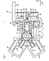
- Numeral 11 designates a bed for a machining center 10 and the bed 11 is installed in a pit dug from the floor surface FL.
- the bed 11 is integrally formed by a column sliding portion 12 extending in a horizontal X-axis direction and a table sliding portion 13 extending in a horizontal Z-axis direction at right angles to the X-axis.
- the table sliding portion 13 intersects with the column sliding portion 12 to form a T-shape therewith at the rear portion and is integrally formed with the column sliding portion 12.
- a column 14 is movably supported on the column sliding portion 12 of the bed 11 in an X-axis direction.
- a pair of guide rails 15, 16 is fixed on the upper surface of the column sliding portion 12 and is extending in a horizontal X-axis direction in parallel with each other and the column 14 slides along the column sliding portion 12 in an X-axis direction with being guided by the pair of guide rails 15 and 16.
- a ball screw shaft 17 is rotatably supported on the bed 11 via bearings 18 and 19 at both ends between the guide rails 15 and 16 and is extending in an X-axis direction.
- One end (inner side end) of the ball screw shaft 17 passes through the bearing 19 and connected to an X-axis servomotor 20.
- a nut is fixed to an underside surface of the column 14 and engages with the ball screw shaft 17. The column 14 is moved in an X-axis direction by the rotation of the ball screw shaft driven by the X-axis servomotor 20.
- a main spindle head 21 is supported on the column 14 and is slidable in a Y-axis direction which is perpendicular to the horizontal surface and is movable in an up/down direction by a Y-axis servomotor 22 via another ball screw shaft 23.
- a main spindle 24 is rotatably supported on the main spindle head 21 and a tool T is detachably attached to the main spindle 24.
- the main spindle 24 is rotated by a main spindle servomotor 25.
- Awork table 26 is supported on the table sliding portion 13 of the bed 11 and is slidable in a Z-axis direction.
- a pair of guide rails 27 and 28 is fixed on the upper surface of the table sliding portion 13 and is extending in a horizontal Z-axis direction in parallel with each other and the work table 26 slides on the table sliding portion 13 in the Z-axis direction with being guided by the pair of guide rails 27 and 28.
- Ball screw shafts 29 and 30 are rotatably supported on the bed 11 via bearings 31, 32, 54 and 55 at both ends and disposed inside of the guide rails 27 and 28. The ball screw shafts 29 and 30 extend in the Z-axis direction. As viewed in Fig.
- respective left side ends of the ball screw shafts 29 and 30 pass through respective left side bearings 54 and 55 and connected to Z-axis servomotors 33 and 34.
- Nuts are fixed to an underside surface of the work table 26 and engage with the ball screw shafts 29 and 30.
- the work table 26 is moved in a Z-axis direction by the rotations of the ball screw shafts 29 and 30 driven by the Z-axis servomotors 33 and 34.
- a rotary table 35 is supported on the work table 26 and is indexably rotatable about an axial line parallel with the Y-axis.
- the rotary table is indexably rotated by a servomotor via reduction gear mechanism (not shown).
- a pallet clamp device (not shown) is provided on the rotary table 35 for positioning and clamping a pallet 36 carried in.
- a workpiece W to be machined is detachably attached on the pallet 36.
- the bed 11, the column 14 and the work table 26, etc. are covered by a cover 56. and a machining space is provided inside of the cover 56 and the space is secluded from the exterior.
- An openable/closable door 57 for operator is provided on a side surface of the cover 56 in the vicinity of the rear end portion of the side surface of the table sliding portion 13.
- An operation position 38 for the operator is provided at the left side of an inner corner portion 37 formed at the intersection between the side surface of the table sliding portion 13 and the front side surface of the column sliding portion 12 of the bed 11.
- a tool changer 39 is provided at the inner end of the column sliding portion 12 opposite to the operation position 38 and the door 57 for operator across the bed 11.
- the tool changer 39 includes a tool magazine 40 for storing a plurality of tools T and a tool change mechanism 41 for exchanging the tools T between the tool magazine 40 and the main spindle 24.
- the tool magazine 40 is provided side by side with the inner end portion of the column sliding portion 12 in a Z-axis direction and the tool change mechanism 41 is provided at the front side of the inner end portion of the column sliding portion 12.
- a control board 42 accommodating therein a control device for controlling the rotations of the X-axis, the Y-axis, the Z-axis and the main spindle servomotors 20, 22, 23, 33, 34 and 25, etc. is arranged in parallel with a side surface of a front portion of the table sliding portion 13 and is arranged side by side with the openable/closable door 57 for operator which is provided on a side surface of the cover 56 for covering a main body of the machining center in the vicinity of the rear end portion of the side surface of the table sliding portion 13.
- An operation board 43 is provided on the control board 42 at the openable/closable door for operator side thereof facing to the operation position 38.
- the operation board 43 is provided with devices such as switches handled by the operator and a display for monitoring the situation of the machining center operation and is wired with the control board42 and so forth.
- First and second workpiece attaching/detaching devices 44 and 45 are provided adjacent to the front end edge of the table sliding portion 13 and arranged side by side therewith in an X-axis direction.
- the first and the second workpiece attaching/detaching devices or stations 44 and 45 are for detaching a machined workpiece W from the pallet 36 and for attaching an unmachined workpiece W to the pallet 36.
- the work table 26 is moved to a pallet exchange position 46 provided at the front end of the table sliding portion 13 after the machining operation on the workpiece W has been completed.
- a first and second pallet carrying in/out devices 47 and 48 are respectively provided with inclinations in acute angle directions with respect to the Z-axis on both sides thereof to form a V-shape.
- the first and the second pallet carrying in/out devices 47 and 48 carry in or out the pallet 36 between the rotary table 35 on the work table 26 positioned to the pallet exchange position 46 and the first and the second workpiece attaching/detaching devices 44 and 45.
- the operator first confirms the condition or state of the workpiece which has been mounted on the rotary table 35, with standing at the operation position 38 and then pushes a start switch provided on an operation board 43. Then, the NC data memorized in a CNC device accommodated in the control board 42 are read sequentially, and thereby the main spindle 24 is rotated by the main spindle servomotor 25, and the column 14, the main spindle head 21 and the work table 26 are moved by the X-axis, Y-axis and Z-axis servomotors 20, 22, 33 and 34 to machine the workpiece W by the tool T.
- the tool to be used next is indexed to a tool exchange position and the indexed tool is turned by a swivel mechanism to be in parallel with the Z-axis and then waits for the next use at the stand-by position.
- the rotation of the main spindle 24 is stopped and the column 14 and the main spindle head 21 are moved to the tool exchange position where the main spindle 24 and the tool change mechanism 41 are aligned.
- Holding devices provided at both ends of an change arm 49 of the tool change mechanism 41 hold a tool T attached to the main spindle 24 and a tool T in the tool magazine 40 at the stand-by position respectively.
- a tool clamp device provided in the main spindle 24 unclamps the tool T, the change arm 49 advances and swivels 180 degrees around, and then retreats to mount another tool T to be used next to the main spindle 24.
- the column 14, main spindle head 21 and the work table 26 are moved to machine the workpiece W by the newly attached tool T.
- the machining of the workpiece W is completed.
- the work table 26 is moved to position at the pallet exchange position 46 by the Z-axis servomotors 33 and 34.
- the rotary table 35 is rotated to be positioned where the attached pallet 36 faces the second workpiece attaching/detaching device 45 at the pallet exchange position 46 and then a pallet clamp device unclamps the pallet 36.
- An engaging portion of the second pallet carrying in/out device 48 advances to engage with an engaging portion of the pallet 36 and then retreats keeping engagement with the pallet 36 to carry out the pallet 36 to a second attaching/detaching position 51 of the second workpiece attaching/detaching device 45.
- a pair of transfer rails 52, 52 is provided between the pallet exchange position 46 and the second attaching/detaching position 51.
- Each of the transfer rails 52 includes a plurality of rollers projecting from the upper surface thereof.
- An engaging portion of the first pallet carrying in/out device 47 advances to carry in the pallet 36 onto the rotary table 35 from the first attaching/detaching position 50 and then the pallet 36 is clamped by the pallet clamp device.
- a pair of transfer rails 53, 53 is provided between the first attaching/detaching position 50 and the pallet exchange position 46 and each rail 53 is provided with a plurality of rollers projecting from the upper surface thereof.
- an operator may operate the operation board 43 in order to relatively move the tool T and the workpiece W with observing the situation of the machining on the workpiece W by the tool T.
- the operation board 43 is arranged on the control board 42 at the door for operator side of the control board 42, the operator can operate the operation board 43 with facing thereto in front of the operator's body, observing the machining situation in a natural attitude, without necessitating turning around movement as has been the case in a conventional machining center.
- control board 42 is arranged side by side with the front end side of the table sliding portion 13 of the bed11 in parallel with each other, even if the movable distance of the column 14 in an X-axis direction is elongated, the whole width of the area including the column sliding portion 12 of the machining center 10 in an X-axis direction can be shortened, which can eventually decrease the installation area of the machining center 10 and makes it possible upon shipping to load the delivery trailer with the machining center 10 wherein the bed is assembled with the control board 42 and the operation board 43.
- the machining center according to the invention can be applied to a machining center in which a pallet attached a machined workpiece and a pallet attached an unmachined workpiece are exchanged between a table and a workpiece attaching/detaching device and then the unmachined workpiece is machined by a plurality of tools changably attached to a main spindle.
Landscapes
- Engineering & Computer Science (AREA)
- Mechanical Engineering (AREA)
- Machine Tool Units (AREA)
- Feeding Of Workpieces (AREA)
- Auxiliary Devices For Machine Tools (AREA)
- Automatic Tool Replacement In Machine Tools (AREA)
Claims (3)
- Bearbeitungszentrum (10), das aufweist:ein Gestell (11) mit einem Säulenführungsabschnitt (12), der sich in einer horizontalen X-Achsenrichtung erstreckt, und einem Tischführungsabschnitt (13), der sich in einer horizontalen Z-Achse rechtwinklig zu der X-Achse erstreckt und an einem hinteren Endabschnitt den Säulenführungsabschnitt (12) T-förmig schneidet;eine Säule (14), die in eine X-Achsenrichtung bewegbar an dem Säulenführungsabschnitt (12) des Gestells (11) gehalten ist;einen Hauptspindelkopf (21), der in eine Y-Achsenrichtung senkrecht zu einer horizontalen Fläche führbar an der Säule (14) gehalten ist und eine Hauptspindel (24) drehbar hält, an der ein Werkzeug (T) abnehmbar angebracht ist;einen Arbeitstisch (26), der in eine Z-Achsenrichtung bewegbar an dem Tischführungsabschnitt (13) des Gestells (11) gehalten ist;dadurch gekennzeichnet, dass das Bearbeitungszentrum (10) ferner aufweist:eine zu öffnende / schließbare Tür (57) für einen Maschinenführer,die an einer Seitenfläche einer Abdeckung (56) vorgesehen ist, um einen Hauptkörper des Bearbeitungszentrums (10) in der Nähe des hinteren Endabschnitts der Seitenfläche des Tischführungsabschnitts (13) abzudecken;eine Steuertafel (42), die parallel zu einer Seitenfläche eines vorderen Abschnitts des Tischführungsabschnitts (13) vorgesehen ist und nebeneinander mit der zu öffnenden / schließbaren Tür (70) für einen Maschinenführer angeordnet ist,einen Drehtisch (35), der an dem Arbeitstisch (26) gehalten ist, um um eine zu der Y-Achse parallele axiale Linie indexiert drehen zu können, und angepasst ist, um eine Palette (36) festzuhalten, auf der ein Werkstück (W) abnehmbar angebracht ist;eine erste Werkstück-Anbring-/Abnehmvorrichtung (44) und eine zweite Werkstück-Anbring-/Abnehmvorrichtung (45), die in der X-Achsenrichtung nebeneinander vorgesehen sind und benachbart zu einer vorderen Endkante des Tischführungsabschnitts (13) angeordnet sind, um das Werkstück (W) an der Palette (36) anzubringen oder davon abzunehmen; undeine erste Paletten-Zuführ-/Abführvorrichtung (47) und eine zweite Paletten-Zuführ-/Abführvorrichtung (48), die mit einer Schiefstellung in Richtung eines spitzen Winkels relativ zu der Z-Achse an beiden Seiten von dieser vorgesehen sind, zum jeweiligen Zuführen- oder Abführen der Palette (36) zwischen dem Drehtisch (35), der an der Arbeitspalette (26) gehalten ist, die zu einer an einem vorderen Endabschnitt des Tischführungsabschnitts (13) vorgesehenen Palettenwechselposition bewegt worden ist, und der ersten und der zweiten Werkstück-Anbring-/Abnehmvorrichtung (44, 45),wobei die Steuertafel (42) zwischen der ersten oder zweiten Paletten-Zuführ-/Abführvorrichtung (47, 48) und einer Seitenfläche des Säulenführungsabschnitts (12) vorgesehen ist.
- Bearbeitungszentrum (10) nach Anspruch 1, wobei eine Bedientafel (43) an der Steuertafel (42) an der zu öffnenden / schließbaren Tür (57) für eine Maschinenführerseite vorgesehen ist.
- Bearbeitungszentrum (10) nach einem der Ansprüche 1 oder 2, das ferner einen automatischen Werkzeugwechsler (39) mit einem Werkzeugmagazin (40) zum Aufbewahren einer Vielzahl Werkzeuge (T) und einen Werkzeugwechselmechanismus (41) zum Wechseln der Werkzeuge (T) zwischen dem Werkzeugmagazin (40) und der Hauptspindel (24) aufweist, wobei der automatische Werkzeugwechsler (39) über das Gestell (11) hinweg der zu öffnenden / schließbaren Tür (57) für den Maschinenführer gegenüberliegenden Seite angeordnet ist.
Applications Claiming Priority (2)
| Application Number | Priority Date | Filing Date | Title |
|---|---|---|---|
| JP2007284472A JP5191211B2 (ja) | 2007-10-31 | 2007-10-31 | マシニングセンタ |
| PCT/JP2008/069261 WO2009057508A1 (ja) | 2007-10-31 | 2008-10-23 | マシニングセンタ |
Publications (3)
| Publication Number | Publication Date |
|---|---|
| EP2208570A1 EP2208570A1 (de) | 2010-07-21 |
| EP2208570A4 EP2208570A4 (de) | 2011-05-04 |
| EP2208570B1 true EP2208570B1 (de) | 2012-05-30 |
Family
ID=40590899
Family Applications (1)
| Application Number | Title | Priority Date | Filing Date |
|---|---|---|---|
| EP08843670A Active EP2208570B1 (de) | 2007-10-31 | 2008-10-23 | Bearbeitungszentrum |
Country Status (5)
| Country | Link |
|---|---|
| US (1) | US8573908B2 (de) |
| EP (1) | EP2208570B1 (de) |
| JP (1) | JP5191211B2 (de) |
| CN (1) | CN101842187B (de) |
| WO (1) | WO2009057508A1 (de) |
Families Citing this family (6)
| Publication number | Priority date | Publication date | Assignee | Title |
|---|---|---|---|---|
| JP5740636B2 (ja) | 2010-09-06 | 2015-06-24 | Dmg森精機株式会社 | 工作機械のパレット交換装置 |
| JP5331175B2 (ja) * | 2011-08-24 | 2013-10-30 | 出光工業株式会社 | 絶縁スペーサの溝加工装置及びその溝加工方法 |
| CN103608147B (zh) * | 2012-06-15 | 2015-04-15 | 山崎马扎克公司 | 加工中心 |
| DE212013000212U1 (de) * | 2012-10-10 | 2015-05-13 | Dmg Mori Seiki Co., Ltd. | Werkzeugmaschinen |
| JP7472686B2 (ja) | 2020-07-01 | 2024-04-23 | 株式会社ジェイテクト | 加工システム |
| CN114453948B (zh) * | 2022-03-15 | 2023-03-28 | 华北理工大学 | 一种具有刀具存放装置的加工中心 |
Family Cites Families (18)
| Publication number | Priority date | Publication date | Assignee | Title |
|---|---|---|---|---|
| US3824892A (en) * | 1971-07-28 | 1974-07-23 | Ex Cell O Corp | Machine tool with automatic tool changing means |
| JPS55112753A (en) * | 1979-02-13 | 1980-08-30 | Toyoda Mach Works Ltd | Numerically controlled machine tool with pallet replacing function |
| US4673076B1 (en) * | 1984-09-04 | 2000-02-01 | Kearney & Trecker Corp | Rotary shuttle for machine tools |
| JPH0197541A (ja) * | 1987-10-07 | 1989-04-17 | Brother Ind Ltd | 工作機械 |
| JPH024739U (de) * | 1988-06-22 | 1990-01-12 | ||
| JPH0747253B2 (ja) * | 1989-10-02 | 1995-05-24 | 日立精機株式会社 | 工具退避装置付多軸スピンドル型マシニングセンタ |
| JPH0741503B2 (ja) * | 1990-04-27 | 1995-05-10 | オ−クマ株式会社 | 自動パレット交換装置のドア―連動機構 |
| US5265497A (en) * | 1992-09-08 | 1993-11-30 | Cincinnati Milacron Inc. | Guard for operator access station |
| DE4307482A1 (de) * | 1993-03-10 | 1994-09-22 | Max Rhodius Gmbh | Werkzeugmaschine |
| US5261147A (en) * | 1993-03-17 | 1993-11-16 | Cincinnati Milacron Inc. | Indexing system |
| JP3121731B2 (ja) | 1994-08-23 | 2001-01-09 | 日立機電工業株式会社 | 除塵機における駆動装置 |
| JPH1133854A (ja) * | 1997-07-25 | 1999-02-09 | Brother Ind Ltd | 工作機械 |
| US6082939A (en) * | 1998-07-09 | 2000-07-04 | Toyoda Koki Kabushiki Kaisha | Machine tool and cover apparatus therefor |
| US6193048B1 (en) * | 1998-11-24 | 2001-02-27 | Midaco Corporation | Pallet changer |
| JP2000176784A (ja) * | 1998-12-08 | 2000-06-27 | Niigata Eng Co Ltd | 工作機械におけるスプラッシュカバーの開閉装置 |
| JP2002337032A (ja) * | 2001-05-11 | 2002-11-26 | Oaku Seiko:Kk | マシニングセンタにおけるワーク座標点への倍速位置決め方法とその方法を実施するための装置 |
| CN1559754A (zh) * | 2004-02-26 | 2005-01-05 | 云南省机械研究设计院 | 一种加工模具的激光加工中心 |
| JP2007152506A (ja) * | 2005-12-06 | 2007-06-21 | Mitsui Seiki Kogyo Co Ltd | 立型マシニングセンタにおけるパレットチェンジャとオペレータの配置構造 |
-
2007
- 2007-10-31 JP JP2007284472A patent/JP5191211B2/ja active Active
-
2008
- 2008-10-23 CN CN2008801135210A patent/CN101842187B/zh active Active
- 2008-10-23 EP EP08843670A patent/EP2208570B1/de active Active
- 2008-10-23 US US12/740,029 patent/US8573908B2/en active Active
- 2008-10-23 WO PCT/JP2008/069261 patent/WO2009057508A1/ja not_active Ceased
Also Published As
| Publication number | Publication date |
|---|---|
| EP2208570A1 (de) | 2010-07-21 |
| US20100266355A1 (en) | 2010-10-21 |
| WO2009057508A1 (ja) | 2009-05-07 |
| CN101842187A (zh) | 2010-09-22 |
| EP2208570A4 (de) | 2011-05-04 |
| US8573908B2 (en) | 2013-11-05 |
| CN101842187B (zh) | 2012-01-11 |
| JP5191211B2 (ja) | 2013-05-08 |
| JP2009107099A (ja) | 2009-05-21 |
Similar Documents
| Publication | Publication Date | Title |
|---|---|---|
| EP2208570B1 (de) | Bearbeitungszentrum | |
| US8887360B2 (en) | Composite working lathe | |
| US4359815A (en) | Machining center with a robot | |
| JP4901884B2 (ja) | 工作機械 | |
| EP1116548A2 (de) | Werkzeugmaschine mit einer vertikal angeordneten Hauptspindel und Verfahren zur ihrer Herstellung | |
| US6178608B1 (en) | Rotary transfer machine | |
| US20090099680A1 (en) | Manufacturing equipment | |
| JP5342074B1 (ja) | マシニングセンタ | |
| EP3147052A1 (de) | Revolverschneidwerkzeughalter und maschinenwerkzeug damit | |
| US20170282322A1 (en) | Machine tool system and workpiece transport method | |
| US10906147B2 (en) | Machine tool and machine tool system | |
| KR102562141B1 (ko) | 공작기계 | |
| JP3985998B2 (ja) | 複合加工用工作機械 | |
| WO2026004624A1 (ja) | 表示制御装置 | |
| JP3379115B2 (ja) | 加工システム | |
| KR20230130357A (ko) | 공작기계의 매거진 | |
| US7909154B2 (en) | Pallet exchanger | |
| JP2024152428A (ja) | 加工システム | |
| WO2022249404A1 (ja) | 自動パレット交換装置 | |
| KR102400839B1 (ko) | 공작기계용 조작패널 유닛 | |
| WO2026004177A1 (ja) | 搬送システムおよびロボット | |
| WO2023249050A1 (ja) | 加工システム | |
| JPH077045Y2 (ja) | 工作機械 | |
| CN120307020A (zh) | 一种数控机床加工自动化生产线 | |
| JPS6334835Y2 (de) |
Legal Events
| Date | Code | Title | Description |
|---|---|---|---|
| PUAI | Public reference made under article 153(3) epc to a published international application that has entered the european phase |
Free format text: ORIGINAL CODE: 0009012 |
|
| 17P | Request for examination filed |
Effective date: 20100421 |
|
| AK | Designated contracting states |
Kind code of ref document: A1 Designated state(s): AT BE BG CH CY CZ DE DK EE ES FI FR GB GR HR HU IE IS IT LI LT LU LV MC MT NL NO PL PT RO SE SI SK TR |
|
| AX | Request for extension of the european patent |
Extension state: AL BA MK RS |
|
| DAX | Request for extension of the european patent (deleted) | ||
| A4 | Supplementary search report drawn up and despatched |
Effective date: 20110404 |
|
| GRAP | Despatch of communication of intention to grant a patent |
Free format text: ORIGINAL CODE: EPIDOSNIGR1 |
|
| GRAS | Grant fee paid |
Free format text: ORIGINAL CODE: EPIDOSNIGR3 |
|
| GRAA | (expected) grant |
Free format text: ORIGINAL CODE: 0009210 |
|
| AK | Designated contracting states |
Kind code of ref document: B1 Designated state(s): AT BE BG CH CY CZ DE DK EE ES FI FR GB GR HR HU IE IS IT LI LT LU LV MC MT NL NO PL PT RO SE SI SK TR |
|
| REG | Reference to a national code |
Ref country code: GB Ref legal event code: FG4D |
|
| REG | Reference to a national code |
Ref country code: CH Ref legal event code: EP |
|
| REG | Reference to a national code |
Ref country code: AT Ref legal event code: REF Ref document number: 559832 Country of ref document: AT Kind code of ref document: T Effective date: 20120615 |
|
| REG | Reference to a national code |
Ref country code: IE Ref legal event code: FG4D |
|
| REG | Reference to a national code |
Ref country code: DE Ref legal event code: R096 Ref document number: 602008016072 Country of ref document: DE Effective date: 20120726 |
|
| REG | Reference to a national code |
Ref country code: NL Ref legal event code: VDEP Effective date: 20120530 |
|
| REG | Reference to a national code |
Ref country code: LT Ref legal event code: MG4D Effective date: 20120530 |
|
| PG25 | Lapsed in a contracting state [announced via postgrant information from national office to epo] |
Ref country code: LT Free format text: LAPSE BECAUSE OF FAILURE TO SUBMIT A TRANSLATION OF THE DESCRIPTION OR TO PAY THE FEE WITHIN THE PRESCRIBED TIME-LIMIT Effective date: 20120530 Ref country code: SE Free format text: LAPSE BECAUSE OF FAILURE TO SUBMIT A TRANSLATION OF THE DESCRIPTION OR TO PAY THE FEE WITHIN THE PRESCRIBED TIME-LIMIT Effective date: 20120530 Ref country code: FI Free format text: LAPSE BECAUSE OF FAILURE TO SUBMIT A TRANSLATION OF THE DESCRIPTION OR TO PAY THE FEE WITHIN THE PRESCRIBED TIME-LIMIT Effective date: 20120530 Ref country code: CY Free format text: LAPSE BECAUSE OF FAILURE TO SUBMIT A TRANSLATION OF THE DESCRIPTION OR TO PAY THE FEE WITHIN THE PRESCRIBED TIME-LIMIT Effective date: 20120530 Ref country code: IS Free format text: LAPSE BECAUSE OF FAILURE TO SUBMIT A TRANSLATION OF THE DESCRIPTION OR TO PAY THE FEE WITHIN THE PRESCRIBED TIME-LIMIT Effective date: 20120930 Ref country code: NO Free format text: LAPSE BECAUSE OF FAILURE TO SUBMIT A TRANSLATION OF THE DESCRIPTION OR TO PAY THE FEE WITHIN THE PRESCRIBED TIME-LIMIT Effective date: 20120830 |
|
| REG | Reference to a national code |
Ref country code: AT Ref legal event code: MK05 Ref document number: 559832 Country of ref document: AT Kind code of ref document: T Effective date: 20120530 |
|
| PG25 | Lapsed in a contracting state [announced via postgrant information from national office to epo] |
Ref country code: HR Free format text: LAPSE BECAUSE OF FAILURE TO SUBMIT A TRANSLATION OF THE DESCRIPTION OR TO PAY THE FEE WITHIN THE PRESCRIBED TIME-LIMIT Effective date: 20120530 Ref country code: GR Free format text: LAPSE BECAUSE OF FAILURE TO SUBMIT A TRANSLATION OF THE DESCRIPTION OR TO PAY THE FEE WITHIN THE PRESCRIBED TIME-LIMIT Effective date: 20120831 Ref country code: LV Free format text: LAPSE BECAUSE OF FAILURE TO SUBMIT A TRANSLATION OF THE DESCRIPTION OR TO PAY THE FEE WITHIN THE PRESCRIBED TIME-LIMIT Effective date: 20120530 Ref country code: SI Free format text: LAPSE BECAUSE OF FAILURE TO SUBMIT A TRANSLATION OF THE DESCRIPTION OR TO PAY THE FEE WITHIN THE PRESCRIBED TIME-LIMIT Effective date: 20120530 |
|
| PG25 | Lapsed in a contracting state [announced via postgrant information from national office to epo] |
Ref country code: BE Free format text: LAPSE BECAUSE OF FAILURE TO SUBMIT A TRANSLATION OF THE DESCRIPTION OR TO PAY THE FEE WITHIN THE PRESCRIBED TIME-LIMIT Effective date: 20120530 |
|
| PG25 | Lapsed in a contracting state [announced via postgrant information from national office to epo] |
Ref country code: RO Free format text: LAPSE BECAUSE OF FAILURE TO SUBMIT A TRANSLATION OF THE DESCRIPTION OR TO PAY THE FEE WITHIN THE PRESCRIBED TIME-LIMIT Effective date: 20120530 Ref country code: EE Free format text: LAPSE BECAUSE OF FAILURE TO SUBMIT A TRANSLATION OF THE DESCRIPTION OR TO PAY THE FEE WITHIN THE PRESCRIBED TIME-LIMIT Effective date: 20120530 Ref country code: CZ Free format text: LAPSE BECAUSE OF FAILURE TO SUBMIT A TRANSLATION OF THE DESCRIPTION OR TO PAY THE FEE WITHIN THE PRESCRIBED TIME-LIMIT Effective date: 20120530 Ref country code: SK Free format text: LAPSE BECAUSE OF FAILURE TO SUBMIT A TRANSLATION OF THE DESCRIPTION OR TO PAY THE FEE WITHIN THE PRESCRIBED TIME-LIMIT Effective date: 20120530 Ref country code: AT Free format text: LAPSE BECAUSE OF FAILURE TO SUBMIT A TRANSLATION OF THE DESCRIPTION OR TO PAY THE FEE WITHIN THE PRESCRIBED TIME-LIMIT Effective date: 20120530 Ref country code: DK Free format text: LAPSE BECAUSE OF FAILURE TO SUBMIT A TRANSLATION OF THE DESCRIPTION OR TO PAY THE FEE WITHIN THE PRESCRIBED TIME-LIMIT Effective date: 20120530 Ref country code: NL Free format text: LAPSE BECAUSE OF FAILURE TO SUBMIT A TRANSLATION OF THE DESCRIPTION OR TO PAY THE FEE WITHIN THE PRESCRIBED TIME-LIMIT Effective date: 20120530 |
|
| PG25 | Lapsed in a contracting state [announced via postgrant information from national office to epo] |
Ref country code: PL Free format text: LAPSE BECAUSE OF FAILURE TO SUBMIT A TRANSLATION OF THE DESCRIPTION OR TO PAY THE FEE WITHIN THE PRESCRIBED TIME-LIMIT Effective date: 20120530 Ref country code: PT Free format text: LAPSE BECAUSE OF FAILURE TO SUBMIT A TRANSLATION OF THE DESCRIPTION OR TO PAY THE FEE WITHIN THE PRESCRIBED TIME-LIMIT Effective date: 20121001 Ref country code: IT Free format text: LAPSE BECAUSE OF FAILURE TO SUBMIT A TRANSLATION OF THE DESCRIPTION OR TO PAY THE FEE WITHIN THE PRESCRIBED TIME-LIMIT Effective date: 20120530 |
|
| PLBE | No opposition filed within time limit |
Free format text: ORIGINAL CODE: 0009261 |
|
| STAA | Information on the status of an ep patent application or granted ep patent |
Free format text: STATUS: NO OPPOSITION FILED WITHIN TIME LIMIT |
|
| PG25 | Lapsed in a contracting state [announced via postgrant information from national office to epo] |
Ref country code: ES Free format text: LAPSE BECAUSE OF FAILURE TO SUBMIT A TRANSLATION OF THE DESCRIPTION OR TO PAY THE FEE WITHIN THE PRESCRIBED TIME-LIMIT Effective date: 20120910 |
|
| 26N | No opposition filed |
Effective date: 20130301 |
|
| PG25 | Lapsed in a contracting state [announced via postgrant information from national office to epo] |
Ref country code: MC Free format text: LAPSE BECAUSE OF NON-PAYMENT OF DUE FEES Effective date: 20121031 |
|
| REG | Reference to a national code |
Ref country code: CH Ref legal event code: PL |
|
| GBPC | Gb: european patent ceased through non-payment of renewal fee |
Effective date: 20121023 |
|
| REG | Reference to a national code |
Ref country code: DE Ref legal event code: R097 Ref document number: 602008016072 Country of ref document: DE Effective date: 20130301 |
|
| REG | Reference to a national code |
Ref country code: IE Ref legal event code: MM4A |
|
| REG | Reference to a national code |
Ref country code: FR Ref legal event code: ST Effective date: 20130628 |
|
| PG25 | Lapsed in a contracting state [announced via postgrant information from national office to epo] |
Ref country code: IE Free format text: LAPSE BECAUSE OF NON-PAYMENT OF DUE FEES Effective date: 20121023 Ref country code: LI Free format text: LAPSE BECAUSE OF NON-PAYMENT OF DUE FEES Effective date: 20121031 Ref country code: CH Free format text: LAPSE BECAUSE OF NON-PAYMENT OF DUE FEES Effective date: 20121031 Ref country code: BG Free format text: LAPSE BECAUSE OF FAILURE TO SUBMIT A TRANSLATION OF THE DESCRIPTION OR TO PAY THE FEE WITHIN THE PRESCRIBED TIME-LIMIT Effective date: 20120830 Ref country code: GB Free format text: LAPSE BECAUSE OF NON-PAYMENT OF DUE FEES Effective date: 20121023 |
|
| PG25 | Lapsed in a contracting state [announced via postgrant information from national office to epo] |
Ref country code: FR Free format text: LAPSE BECAUSE OF NON-PAYMENT OF DUE FEES Effective date: 20121031 |
|
| PG25 | Lapsed in a contracting state [announced via postgrant information from national office to epo] |
Ref country code: MT Free format text: LAPSE BECAUSE OF FAILURE TO SUBMIT A TRANSLATION OF THE DESCRIPTION OR TO PAY THE FEE WITHIN THE PRESCRIBED TIME-LIMIT Effective date: 20120530 |
|
| PG25 | Lapsed in a contracting state [announced via postgrant information from national office to epo] |
Ref country code: TR Free format text: LAPSE BECAUSE OF FAILURE TO SUBMIT A TRANSLATION OF THE DESCRIPTION OR TO PAY THE FEE WITHIN THE PRESCRIBED TIME-LIMIT Effective date: 20120530 |
|
| PG25 | Lapsed in a contracting state [announced via postgrant information from national office to epo] |
Ref country code: LU Free format text: LAPSE BECAUSE OF NON-PAYMENT OF DUE FEES Effective date: 20121023 |
|
| PG25 | Lapsed in a contracting state [announced via postgrant information from national office to epo] |
Ref country code: HU Free format text: LAPSE BECAUSE OF FAILURE TO SUBMIT A TRANSLATION OF THE DESCRIPTION OR TO PAY THE FEE WITHIN THE PRESCRIBED TIME-LIMIT Effective date: 20081023 |
|
| PGFP | Annual fee paid to national office [announced via postgrant information from national office to epo] |
Ref country code: DE Payment date: 20250902 Year of fee payment: 18 |