EP2207727B1 - Container - Google Patents
Container Download PDFInfo
- Publication number
- EP2207727B1 EP2207727B1 EP08851024.3A EP08851024A EP2207727B1 EP 2207727 B1 EP2207727 B1 EP 2207727B1 EP 08851024 A EP08851024 A EP 08851024A EP 2207727 B1 EP2207727 B1 EP 2207727B1
- Authority
- EP
- European Patent Office
- Prior art keywords
- wall
- container
- cover
- sealing portion
- radius
- Prior art date
- Legal status (The legal status is an assumption and is not a legal conclusion. Google has not performed a legal analysis and makes no representation as to the accuracy of the status listed.)
- Revoked
Links
Images

Classifications
-
- B—PERFORMING OPERATIONS; TRANSPORTING
- B65—CONVEYING; PACKING; STORING; HANDLING THIN OR FILAMENTARY MATERIAL
- B65D—CONTAINERS FOR STORAGE OR TRANSPORT OF ARTICLES OR MATERIALS, e.g. BAGS, BARRELS, BOTTLES, BOXES, CANS, CARTONS, CRATES, DRUMS, JARS, TANKS, HOPPERS, FORWARDING CONTAINERS; ACCESSORIES, CLOSURES, OR FITTINGS THEREFOR; PACKAGING ELEMENTS; PACKAGES
- B65D43/00—Lids or covers for rigid or semi-rigid containers
- B65D43/14—Non-removable lids or covers
- B65D43/16—Non-removable lids or covers hinged for upward or downward movement
- B65D43/162—Non-removable lids or covers hinged for upward or downward movement the container, the lid and the hinge being made of one piece
-
- B—PERFORMING OPERATIONS; TRANSPORTING
- B65—CONVEYING; PACKING; STORING; HANDLING THIN OR FILAMENTARY MATERIAL
- B65D—CONTAINERS FOR STORAGE OR TRANSPORT OF ARTICLES OR MATERIALS, e.g. BAGS, BARRELS, BOTTLES, BOXES, CANS, CARTONS, CRATES, DRUMS, JARS, TANKS, HOPPERS, FORWARDING CONTAINERS; ACCESSORIES, CLOSURES, OR FITTINGS THEREFOR; PACKAGING ELEMENTS; PACKAGES
- B65D43/00—Lids or covers for rigid or semi-rigid containers
- B65D43/14—Non-removable lids or covers
- B65D43/16—Non-removable lids or covers hinged for upward or downward movement
- B65D43/163—Non-removable lids or covers hinged for upward or downward movement the container and the lid being made separately
- B65D43/169—Non-removable lids or covers hinged for upward or downward movement the container and the lid being made separately the lid, the hinge and the element connecting them to the container being made of one piece
-
- B—PERFORMING OPERATIONS; TRANSPORTING
- B65—CONVEYING; PACKING; STORING; HANDLING THIN OR FILAMENTARY MATERIAL
- B65D—CONTAINERS FOR STORAGE OR TRANSPORT OF ARTICLES OR MATERIALS, e.g. BAGS, BARRELS, BOTTLES, BOXES, CANS, CARTONS, CRATES, DRUMS, JARS, TANKS, HOPPERS, FORWARDING CONTAINERS; ACCESSORIES, CLOSURES, OR FITTINGS THEREFOR; PACKAGING ELEMENTS; PACKAGES
- B65D2543/00—Lids or covers essentially for box-like containers
- B65D2543/00009—Details of lids or covers for rigid or semi-rigid containers
- B65D2543/00444—Contact between the container and the lid
- B65D2543/00481—Contact between the container and the lid on the inside or the outside of the container
- B65D2543/0049—Contact between the container and the lid on the inside or the outside of the container on the inside, or a part turned to the inside of the mouth of the container
- B65D2543/00518—Skirt
-
- B—PERFORMING OPERATIONS; TRANSPORTING
- B65—CONVEYING; PACKING; STORING; HANDLING THIN OR FILAMENTARY MATERIAL
- B65D—CONTAINERS FOR STORAGE OR TRANSPORT OF ARTICLES OR MATERIALS, e.g. BAGS, BARRELS, BOTTLES, BOXES, CANS, CARTONS, CRATES, DRUMS, JARS, TANKS, HOPPERS, FORWARDING CONTAINERS; ACCESSORIES, CLOSURES, OR FITTINGS THEREFOR; PACKAGING ELEMENTS; PACKAGES
- B65D2543/00—Lids or covers essentially for box-like containers
- B65D2543/00009—Details of lids or covers for rigid or semi-rigid containers
- B65D2543/00444—Contact between the container and the lid
- B65D2543/00592—Snapping means
- B65D2543/00601—Snapping means on the container
- B65D2543/00611—Profiles
- B65D2543/00629—Massive bead
-
- B—PERFORMING OPERATIONS; TRANSPORTING
- B65—CONVEYING; PACKING; STORING; HANDLING THIN OR FILAMENTARY MATERIAL
- B65D—CONTAINERS FOR STORAGE OR TRANSPORT OF ARTICLES OR MATERIALS, e.g. BAGS, BARRELS, BOTTLES, BOXES, CANS, CARTONS, CRATES, DRUMS, JARS, TANKS, HOPPERS, FORWARDING CONTAINERS; ACCESSORIES, CLOSURES, OR FITTINGS THEREFOR; PACKAGING ELEMENTS; PACKAGES
- B65D2543/00—Lids or covers essentially for box-like containers
- B65D2543/00009—Details of lids or covers for rigid or semi-rigid containers
- B65D2543/00444—Contact between the container and the lid
- B65D2543/00592—Snapping means
- B65D2543/00601—Snapping means on the container
- B65D2543/00675—Periphery concerned
- B65D2543/00685—Totality
-
- B—PERFORMING OPERATIONS; TRANSPORTING
- B65—CONVEYING; PACKING; STORING; HANDLING THIN OR FILAMENTARY MATERIAL
- B65D—CONTAINERS FOR STORAGE OR TRANSPORT OF ARTICLES OR MATERIALS, e.g. BAGS, BARRELS, BOTTLES, BOXES, CANS, CARTONS, CRATES, DRUMS, JARS, TANKS, HOPPERS, FORWARDING CONTAINERS; ACCESSORIES, CLOSURES, OR FITTINGS THEREFOR; PACKAGING ELEMENTS; PACKAGES
- B65D2543/00—Lids or covers essentially for box-like containers
- B65D2543/00009—Details of lids or covers for rigid or semi-rigid containers
- B65D2543/00444—Contact between the container and the lid
- B65D2543/00592—Snapping means
- B65D2543/00712—Snapping means on the lid
- B65D2543/00722—Profiles
- B65D2543/0074—Massive bead
-
- B—PERFORMING OPERATIONS; TRANSPORTING
- B65—CONVEYING; PACKING; STORING; HANDLING THIN OR FILAMENTARY MATERIAL
- B65D—CONTAINERS FOR STORAGE OR TRANSPORT OF ARTICLES OR MATERIALS, e.g. BAGS, BARRELS, BOTTLES, BOXES, CANS, CARTONS, CRATES, DRUMS, JARS, TANKS, HOPPERS, FORWARDING CONTAINERS; ACCESSORIES, CLOSURES, OR FITTINGS THEREFOR; PACKAGING ELEMENTS; PACKAGES
- B65D2543/00—Lids or covers essentially for box-like containers
- B65D2543/00009—Details of lids or covers for rigid or semi-rigid containers
- B65D2543/00444—Contact between the container and the lid
- B65D2543/00592—Snapping means
- B65D2543/00712—Snapping means on the lid
- B65D2543/00787—Periphery concerned
- B65D2543/00796—Totality
Definitions
- the present invention relates to a container for receiving loosely stored products, such as drugs, pills, tablets, test strips, granulate and even powder which has a container body and a cover, whereby a hinge is placed between the container body and the cover.
- the container has to be airtight in order to avoid a deterioration of the stored products.
- Containers of the above mentioned type are known and common to the skilled in the art. They usually comprise a cover that is integrally attached to the container, wherein the cover has a circular base with an outer periphery and a cylindrical tubular skirt extending perpendicularly and outwardly around the outer periphery of the base. Furthermore such containers have also an upper portion and an inner and outer surface, wherein the container having a cylindrical upstanding rim at the upper portion, the rim is defined as that portion of the container that contacts an inner wall of the skirt of the cover, and the rim having an inner and outer wall rim. Further, such covers comprise a thumb tab for facilitating the opening and closing of the container and at least one hinge attached to the container. The hinge has at least one hinge recess bend point that functions to rotate the cover at one pivot point. The thumb tab and the hinge are positioned on substantially opposing ends of the cover and extending, perpendicularly and outwardly from the skirt of the cover.
- a flexible lip is often part of such containers, whereby the flexible lip is a projection that projects concentrically from an interior surface of the base of the cover.
- the skirt of the cover overlies the container and at least a portion of the rim of the container engages the inner wall of the skirt of the cover, the flexible lip interacts with the rim to sufficiently deflect so as to form a releasable seal between the cover and the container.
- WO 2005/074571 A2 discloses an integral container and cap assembly according to the preamble of claim 1 wherein a hinge is placed between the container body and the cap. A flexible lip projects concentrically from an interior surface of the base of the cap.
- the resealable container according to US 6,769,558 B1 consists essentially of a container having a rim at its upper portion, and a cap having a circular base with an outer periphery, a cylindrical tubular skirt, the inner wall of which has at least one recess, and a hinge connecting the cap to the container.
- the skirt of cap In a closed position, the skirt of cap overlies the container and the rim of the container is situated within the recess of the inner wall of the skirt of the cap.
- WO 2004/031046 A relates to a container having a container body and a lid connected to it.
- the container comprises a recess or projection on its outer wall adjacent to its dispensing aperture, and the lid comprises a connecting land extending outwards from its peripheral rim.
- the recess or projection of the container can be brought in engagement with a projection or recess of the connecting land.
- US 4 982 872 A discloses a sheath encapsulated container.
- the sheath encapsulating the structure of the container allows for using reused or recycled material for this structure.
- FR 2 858 301 A1 describes a desiccant container comprising a tubular casing and a closure, wherein the closure and the casing are configured to provide several surface-to-surface seals.
- US 2 990 077 A relates to closure devices for containers which closure devices are configured to form also means for maintaining the closure device releasably in its open position.
- the aim of this invention is to provide a container of the above mentioned type, which has an improved tightness even when opened and closed several times, can be easily manufactured and provides an improved reliability.
- the invention provides a container for loosely stored products comprising a container body a cover and a hinge, placed between the container body and the cover wherein the cover has a cylindrical inner wall and a cylindrical outer wall wherein the inner wall is provided with a sealing portion at the outer edge of the inner wall wherein the vertical position of an apex of the sealing portion is smaller than the vertical height of the outer wall.
- the sealing portion is provided at the outer edge of the inner wall and the vertical position of an apex of the sealing portion is smaller than the vertical height of the outer wall the sealing portion is protected against undesired contact by means of the outer wall. Even if the container is shipped or handled in open state the sealing portion of the cover is protected against damages. This increases air tightness of the container and overall reliability due to fail safe handling.
- the apex or sealing line of the sealing portion is arranged within a groove formed between inner and outer wall. This groove is usually very narrow, such that it is unlikely that the apex of the sealing portion at the inner wall is contacted or even damaged.
- the vertical position A of the apex of the sealing portion is 2.0 - 15.0 mm, preferably 2.0 - 10.0 mm, more preferably 3.9 mm, and the vertical height B of the outer wall is 2.1 - 15.1 mm, preferably 2.1 - 10.1 mm, more preferably 4.2 mm.
- the apex of the sealing portion is protected by a preferably 0.3 mm higher outer wall.
- the sealing portion seen in a transversal section is provided with a first radius R1 defining an outer apex.
- the first radius R1 is 0.5 - 3.0 mm, preferably 0.7 - 0.9 mm and more preferably 0.8 mm.
- the sealing portion comprises a rather small radius a well defined contact line with the inner wall surface of the container body results which guarantees on the one hand an improved air-tightness and on the other hand allows opening and closing of the container without damaging the sealing portion.
- the sealing portion comprises a second radius R2 between the first radius R1 and an end surface of the inner wall, wherein the second radius R2 is smaller than the first radius R1.
- the second radius R2 is 0.05 - 2.0 mm, preferably 0.10 - 0.50 mm and more preferably 0.15 mm.
- This second radius eliminates the risk of damaging the inner wall surface of the container body and thereby improves again air-tightness of the container.
- the inner wall further comprises a third radius R3 between a wall surface of the inner wall and the sealing portion.
- the third radius R3 is 1.0 - 3.0 mm, preferably 1.5 mm. This third radius facilitates the production since it avoids any risk of scratching the sealing portion surface when ejecting the cover from its mould.
- the thickness T of the inner wall is between 0.4 - 1,2 mm, preferably about 0.7 mm.
- the thickness of the inner wall is chosen to optimize an the one hand the compression force the sealing portion exerts to the inner surface of the container body flange. On the other hand, it has found out that it is favourable to avoid material accumulations at the sealing portion since the sealing portion is - time wise - the last portion of the injection mould that is filled. By reducing the wall thickness material accumulations are avoided and subsequently material defects like sink marks are avoided. It was found out that the less material is used at the sealing portion the better the final geometry and the better the air tightness of the final container.
- the sealing portion of the inner wall cooperates with an inner side of a flange of the container body in order to air tight seal the container. Since the sealing portion at the container body is the inner side of a flange again the sealing face is protected as good as possible. When compared to the outer side of the flange for example a much better protection of the surface and subsequently a better air tightness results.
- the inner wall further comprises a chamfer opposite to the sealing portion. Since the sealing portion of the inner wall comprises a radius which forms an apex at the outer side a chamfer at the inner side is provided which locally eliminates the increase of the wall thickness in this area. The chamfer therefore further prevents a material accumulation, prevents material defects like sink marks and thereby increases the air tightness of the container.
- said cover is produced independently and separately from said container body and the cover is detachably connected to the container body. This allows producing the cover of a different material than the container body which may further increase air tightness of the container due to a special material selection of both parts.
- the container body comprises a first connecting means and the cover comprises a second connecting means integral with the hinge, wherein the container body and the cover are detachably connected with each other by connecting the first with the second connecting means.
- the hinge can preferably be used for attaching a connection means to the cover.
- the second connecting means is provided with at least one snapping hook and the first connecting means is provided with at least one recess for accommodating the snapping hook in order to connect the cover at the container body.
- This provides a snap connection of cover and container which can be made by simply inserting the second connecting means into the first connecting means.
- the first connecting means is integral with the container body.
- the container consists of only two separate parts container body and cover.
- the hinge is a foil hinge.
- Foil hinges are very reliable and provide an exact rotation axis of the cover with respect to the container body. This facilitates a very exact positioning of the cover during the closing movement which guarantees that the inner wall with the sealing portion is not damaged during closing the cover.
- the container comprises an insert which essentially covers the inner surface of the container body, wherein the insert is made of a different material compared to the container body.
- the inner surface which contacts the stored goods can be made of an appropriate material which can be different to the material of the container body. For example it can be favourable for medical applications to produce the insert of an inert material.
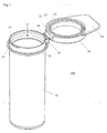
- Fig. 1 shows an air tight container 100 according to the invention.
- the container 100 consists of a container body 10 and a hinged cover 20 and can be used for example to store medical goods such as test strips for blood glucose measurement.
- the container body 10 has an opening 12 which is surrounded by a flange 16.
- the cover 20 can rotate around a foil hinge 22 for closing and opening of the container 100.
- a bead 14 which surrounds the container body 10 extends outwards from the flange 16 and acts as a stop for the cover 20 in closed condition.
- the cover 20 is detachably connected to the container body 10 by means of a first connecting means 18 integral with the container body 10 and a second connecting means 24 integral with the hinge 22.
- the second connecting means 24 comprises two snapping hooks on opposite sides or one snapping hook on the total length of the hinge 22 or a combination of both which engage corresponding recesses at the first connecting means 18. To establish the connection it is just required to insert the second connecting means 24 into the first connecting means 18.
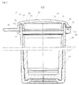
- Fig. 2 shows in a partial sectional view the container 100 in closed condition. Particularly, it shows how the air tight sealing between container body 10 and cover 20 is established.
- the cover 20 comprises a cylindrical inner wall 30 which has the actual sealing and a cylindrical outer wall 32 which basically act for mechanically holding the cover 20 in place.
- the inner wall 30 is provided with a sealing portion 34 at the outer edge of the inner wall 30. This sealing portion cooperates with the inner surface of the flange 16 to air tight seal the container 100.
- the flange 16 is provided with a chamfer 15 at the upper inner side. Further, the inner surface of the flange 16 has is provided very even and smooth.
- the cover 20 is provided with a projection 33 which engages a corresponding protrusion 17 on the outer surface of the flange 16.
- the cover 20 comprises a thumb tab 26 which is arranged below the projection 33 at the outer wall 32. By pressing the thumb tab 26 from below the outer wall 32 bends slightly outwards and the projection 33 moves over of the protrusion 17 and allows the cover 20 to be opened.
- a recess can be provided at the flange 16 and the corresponding projection can be provided at the cover 20.
- the clipping of the cover 20 at the container body 20 is separate from the sealing.
- the seal (apex 36 of sealing portion 34) engages the inner surface flange 16 without any recess. The risk of damaging the sealing surface when opening or closing the cover 20 is therefore significantly reduced.
- Fig. 2 further shows an insert 11 which can be made of a special material within the container body 10.
- the insert is made of a desiccant entrained polymer whereas the cover 20 and the container body 10 are made of PP.
- Figs. 3 and 4 show the details of the cover 20 particularly the elements of the sealing portion 34 at the inner wall 30.
- the sealing portion 34 comprises an apex 36 which is defined by a first radius R1 and which forms the actual contact line with the inner surface of the flange 16.
- the first radius can be 0.5 - 3.0 mm, preferably 0.7 - 0.9 mm and more preferably it is 0.8 mm.
- the apex 36 is arranged at the outer edge of the inner wall 30 and faces the outer wall 32. Between outer wall 32 and inner wall 30 a groove 28 is provided, which accommodates the flange 16 in closed condition of the container 100.
- the vertical position A of the apex 36 is smaller than the vertical height B of the outer wall. Therefore, the outer wall 32 protects the apex 36 from undesired contact with other elements, what may lead to damages of the apex 36 that forms the actual sealing. This leads to an increased reliability of the container 100 in view of air tightness.
- the vertical position A of the apex 36 of the sealing portion 36 can be 2.0 - 15.0 mm, preferably 3.9 mm and the vertical height B of the outer wall 32 can be 2.1 - 15.1 mm, preferably 4.2 mm. Therefore, the apex of the sealing portion is protected by a preferably 0.3 mm higher outer wall 32.
- the sealing portion 34 further comprises a second radius R2 between the first radius R1 and an end surface 35 of the inner wall 30.
- the second radius R2 is smaller than the first radius R1.
- the second radius R2 can be 0.05 - 2.0 mm, preferably 0.10 - 0.50 mm and more preferably 0.15 mm.
- This second radius R1 eliminates the risk of damaging (for example scratching) the inner wall surface of the container body 1.0 and thereby improves again air-tightness of the container 100.
- the small radius R2 ensures that the distance between the apex 36 and the end surface 35 is small such that the sealing line is close to the lower end of the inner wall 36 which has manufacturing advantages. Particularly, this avoids material accumulation at the sealing portion 34 which eliminates defects like sink marks.
- the inner wall 30 comprises a third radius R3 between a wall surface 38 and the sealing portion 34.
- This third radius R3 can be 1.0 - 3.0 mm more preferably 1.5 mm. It facilitates the production of the cover 20 since it avoids any risk of scratching the sealing portion surface when the cover 20 is ejected from its mould.
- the thickness T of the inner wall 30 is chosen to optimize on the one hand the compression force the sealing portion 36 exerts to the inner surface of the container body flange 16. On the other hand, as mentioned above it has found out that it is favourable to avoid material accumulations at the sealing portion 34 since the sealing portion 34 is - time wise - the last portion of the injection mould that is filled. By reducing the wall thickness T material accumulations are avoided and subsequently material defects like sink marks are avoided which improves geometry of the sealing portion 36 and the air tightness of the container 100.
- the thickness T of the inner wall 30 can be 0.4 - 1.2 mm, preferably about 1.2 mm.
- the inner wall 30 further comprises a chamfer 40 opposite to the sealing portion 34.
- Measurements within a climate chamber of moisture uptake showed a significant improvement in view of moisture ingress compared to a different container with a closure that shows an inner wall of the shape indicated by outline 50.
- a container according the invention only had moisture ingress of 0.20 mg a day, whereas a container with the alternative inner wall design 50 showed a moisture ingress of 0.30 mg a day. This means a moisture ingress reduction of 35%.
Landscapes
- Engineering & Computer Science (AREA)
- Mechanical Engineering (AREA)
- Packages (AREA)
- Closures For Containers (AREA)
Description
- The present invention relates to a container for receiving loosely stored products, such as drugs, pills, tablets, test strips, granulate and even powder which has a container body and a cover, whereby a hinge is placed between the container body and the cover. For such purposes the container has to be airtight in order to avoid a deterioration of the stored products.
- Containers of the above mentioned type are known and common to the skilled in the art. They usually comprise a cover that is integrally attached to the container, wherein the cover has a circular base with an outer periphery and a cylindrical tubular skirt extending perpendicularly and outwardly around the outer periphery of the base. Furthermore such containers have also an upper portion and an inner and outer surface, wherein the container having a cylindrical upstanding rim at the upper portion, the rim is defined as that portion of the container that contacts an inner wall of the skirt of the cover, and the rim having an inner and outer wall rim. Further, such covers comprise a thumb tab for facilitating the opening and closing of the container and at least one hinge attached to the container. The hinge has at least one hinge recess bend point that functions to rotate the cover at one pivot point. The thumb tab and the hinge are positioned on substantially opposing ends of the cover and extending, perpendicularly and outwardly from the skirt of the cover.
- A flexible lip is often part of such containers, whereby the flexible lip is a projection that projects concentrically from an interior surface of the base of the cover. When the skirt of the cover overlies the container and at least a portion of the rim of the container engages the inner wall of the skirt of the cover, the flexible lip interacts with the rim to sufficiently deflect so as to form a releasable seal between the cover and the container.
- One of the main criteria of such containers is the air tightness in order to protect the stored products as good as possible. Improved demands in this respect require a very exact manufacturing of the containers particular the sealing portions. In prior art containers reliability of the containers can not be guaranteed due to manufacturing defects at the sealing portions.
- Further, since such containers with hinged covers are intended to be opened and closed several times mainly by hand this may again impair air tightness of the container according the prior art.
-
WO 2005/074571 A2 discloses an integral container and cap assembly according to the preamble ofclaim 1 wherein a hinge is placed between the container body and the cap. A flexible lip projects concentrically from an interior surface of the base of the cap. - The resealable container according to
US 6,769,558 B1 consists essentially of a container having a rim at its upper portion, and a cap having a circular base with an outer periphery, a cylindrical tubular skirt, the inner wall of which has at least one recess, and a hinge connecting the cap to the container. In a closed position, the skirt of cap overlies the container and the rim of the container is situated within the recess of the inner wall of the skirt of the cap. -
WO 2004/031046 A relates to a container having a container body and a lid connected to it. The container comprises a recess or projection on its outer wall adjacent to its dispensing aperture, and the lid comprises a connecting land extending outwards from its peripheral rim. The recess or projection of the container can be brought in engagement with a projection or recess of the connecting land. -
US 4 982 872 A discloses a sheath encapsulated container. The sheath encapsulating the structure of the container allows for using reused or recycled material for this structure. -
FR 2 858 301 A1 -
US 2 990 077 A relates to closure devices for containers which closure devices are configured to form also means for maintaining the closure device releasably in its open position. - Based on the explained disadvantages as well as by considering the explained prior art for containers of the above mentioned art, the aim of this invention is to provide a container of the above mentioned type, which has an improved tightness even when opened and closed several times, can be easily manufactured and provides an improved reliability.
- This goal is achieved according to the invention by
claim 1. Advantageous improvements result from the sub claims. - Particularly the invention provides a container for loosely stored products comprising a container body a cover and a hinge, placed between the container body and the cover wherein the cover has a cylindrical inner wall and a cylindrical outer wall wherein the inner wall is provided with a sealing portion at the outer edge of the inner wall wherein the vertical position of an apex of the sealing portion is smaller than the vertical height of the outer wall.
- Since the sealing portion is provided at the outer edge of the inner wall and the vertical position of an apex of the sealing portion is smaller than the vertical height of the outer wall the sealing portion is protected against undesired contact by means of the outer wall. Even if the container is shipped or handled in open state the sealing portion of the cover is protected against damages. This increases air tightness of the container and overall reliability due to fail safe handling.
- The apex or sealing line of the sealing portion is arranged within a groove formed between inner and outer wall. This groove is usually very narrow, such that it is unlikely that the apex of the sealing portion at the inner wall is contacted or even damaged.
- In a first preferred embodiment the vertical position A of the apex of the sealing portion is 2.0 - 15.0 mm, preferably 2.0 - 10.0 mm, more preferably 3.9 mm, and the vertical height B of the outer wall is 2.1 - 15.1 mm, preferably 2.1 - 10.1 mm, more preferably 4.2 mm. The apex of the sealing portion is protected by a preferably 0.3 mm higher outer wall.
- In a further embodiment the sealing portion seen in a transversal section is provided with a first radius R1 defining an outer apex. In an embodiment the first radius R1 is 0.5 - 3.0 mm, preferably 0.7 - 0.9 mm and more preferably 0.8 mm.
- Since the sealing portion comprises a rather small radius a well defined contact line with the inner wall surface of the container body results which guarantees on the one hand an improved air-tightness and on the other hand allows opening and closing of the container without damaging the sealing portion.
- In a further embodiment the sealing portion comprises a second radius R2 between the first radius R1 and an end surface of the inner wall, wherein the second radius R2 is smaller than the first radius R1. In an embodiment the second radius R2 is 0.05 - 2.0 mm, preferably 0.10 - 0.50 mm and more preferably 0.15 mm.
- This second radius eliminates the risk of damaging the inner wall surface of the container body and thereby improves again air-tightness of the container.
- Preferably, the inner wall further comprises a third radius R3 between a wall surface of the inner wall and the sealing portion. In an embodiment the third radius R3 is 1.0 - 3.0 mm, preferably 1.5 mm. This third radius facilitates the production since it avoids any risk of scratching the sealing portion surface when ejecting the cover from its mould.
- In a further preferred embodiment the thickness T of the inner wall is between 0.4 - 1,2 mm, preferably about 0.7 mm. The thickness of the inner wall is chosen to optimize an the one hand the compression force the sealing portion exerts to the inner surface of the container body flange. On the other hand, it has found out that it is favourable to avoid material accumulations at the sealing portion since the sealing portion is - time wise - the last portion of the injection mould that is filled. By reducing the wall thickness material accumulations are avoided and subsequently material defects like sink marks are avoided. It was found out that the less material is used at the sealing portion the better the final geometry and the better the air tightness of the final container.
- In a further embedment the sealing portion of the inner wall cooperates with an inner side of a flange of the container body in order to air tight seal the container. Since the sealing portion at the container body is the inner side of a flange again the sealing face is protected as good as possible. When compared to the outer side of the flange for example a much better protection of the surface and subsequently a better air tightness results.
- Preferably, the inner wall further comprises a chamfer opposite to the sealing portion. Since the sealing portion of the inner wall comprises a radius which forms an apex at the outer side a chamfer at the inner side is provided which locally eliminates the increase of the wall thickness in this area. The chamfer therefore further prevents a material accumulation, prevents material defects like sink marks and thereby increases the air tightness of the container.
- In a further preferred embodiment said cover is produced independently and separately from said container body and the cover is detachably connected to the container body. This allows producing the cover of a different material than the container body which may further increase air tightness of the container due to a special material selection of both parts.
- Preferably, the container body comprises a first connecting means and the cover comprises a second connecting means integral with the hinge, wherein the container body and the cover are detachably connected with each other by connecting the first with the second connecting means. The hinge can preferably be used for attaching a connection means to the cover.
- Preferably the second connecting means is provided with at least one snapping hook and the first connecting means is provided with at least one recess for accommodating the snapping hook in order to connect the cover at the container body. This provides a snap connection of cover and container which can be made by simply inserting the second connecting means into the first connecting means.
- In a further preferred embodiment the first connecting means is integral with the container body. In this case the container consists of only two separate parts container body and cover.
- Preferably the hinge is a foil hinge. Foil hinges are very reliable and provide an exact rotation axis of the cover with respect to the container body. This facilitates a very exact positioning of the cover during the closing movement which guarantees that the inner wall with the sealing portion is not damaged during closing the cover.
- In a further preferred embodiment the container comprises an insert which essentially covers the inner surface of the container body, wherein the insert is made of a different material compared to the container body. By providing an insert within the container body the inner surface which contacts the stored goods can be made of an appropriate material which can be different to the material of the container body. For example it can be favourable for medical applications to produce the insert of an inert material.
- Further advantages, details and characteristics result from the sub claims.
- In the following an embodiment of the invention will be explained in more detail by means of the figures. Therein shows:
- Fig 1
- is a three dimensional drawing of a container of container body and mounted cover in open condition;
- Fig. 2
- is a partial lateral sectional view of the container according
fig. 1 in closed condition; - Fig. 3
- is a lateral sectional view of a cover of the container according
figs. 1 and2 ; and - Fig. 4
- is an enlarged detail of a lateral sectional view of a cover according
fig. 3 . - In the following preferred embodiments of the invention are shown with respect to the figures.
-
Fig. 1 shows an airtight container 100 according to the invention. Thecontainer 100 consists of acontainer body 10 and a hingedcover 20 and can be used for example to store medical goods such as test strips for blood glucose measurement. Thecontainer body 10 has anopening 12 which is surrounded by aflange 16. Thecover 20 can rotate around afoil hinge 22 for closing and opening of thecontainer 100. - A
bead 14 which surrounds thecontainer body 10 extends outwards from theflange 16 and acts as a stop for thecover 20 in closed condition. - The
cover 20 is detachably connected to thecontainer body 10 by means of a first connectingmeans 18 integral with thecontainer body 10 and a second connectingmeans 24 integral with thehinge 22. The second connectingmeans 24 comprises two snapping hooks on opposite sides or one snapping hook on the total length of thehinge 22 or a combination of both which engage corresponding recesses at the first connectingmeans 18. To establish the connection it is just required to insert the second connecting means 24 into the first connectingmeans 18. -
Fig. 2 shows in a partial sectional view thecontainer 100 in closed condition. Particularly, it shows how the air tight sealing betweencontainer body 10 and cover 20 is established. To this end thecover 20 comprises a cylindricalinner wall 30 which has the actual sealing and a cylindricalouter wall 32 which basically act for mechanically holding thecover 20 in place. - The
inner wall 30 is provided with a sealingportion 34 at the outer edge of theinner wall 30. This sealing portion cooperates with the inner surface of theflange 16 to air tight seal thecontainer 100. - For facilitating the closing of the
cover 20 and to prevent any damages of the sealingportion 34 theflange 16 is provided with achamfer 15 at the upper inner side. Further, the inner surface of theflange 16 has is provided very even and smooth. For holding thecover 20 in place in closed condition it is provided with aprojection 33 which engages a correspondingprotrusion 17 on the outer surface of theflange 16. In order to open thecontainer 100 thecover 20 comprises athumb tab 26 which is arranged below theprojection 33 at theouter wall 32. By pressing thethumb tab 26 from below theouter wall 32 bends slightly outwards and theprojection 33 moves over of theprotrusion 17 and allows thecover 20 to be opened. Of course also a recess can be provided at theflange 16 and the corresponding projection can be provided at thecover 20. - The clipping of the
cover 20 at thecontainer body 20 is separate from the sealing. The seal (apex 36 of sealing portion 34) engages theinner surface flange 16 without any recess. The risk of damaging the sealing surface when opening or closing thecover 20 is therefore significantly reduced. -
Fig. 2 further shows aninsert 11 Which can be made of a special material within thecontainer body 10. Preferably the insert is made of a desiccant entrained polymer whereas thecover 20 and thecontainer body 10 are made of PP. -
Figs. 3 and 4 show the details of thecover 20 particularly the elements of the sealingportion 34 at theinner wall 30. The sealingportion 34 comprises an apex 36 which is defined by a first radius R1 and which forms the actual contact line with the inner surface of theflange 16. The first radius can be 0.5 - 3.0 mm, preferably 0.7 - 0.9 mm and more preferably it is 0.8 mm. - The apex 36 is arranged at the outer edge of the
inner wall 30 and faces theouter wall 32. Betweenouter wall 32 and inner wall 30 agroove 28 is provided, which accommodates theflange 16 in closed condition of thecontainer 100. - As it can be seen in
Fig. 4 , the vertical position A of the apex 36 is smaller than the vertical height B of the outer wall. Therefore, theouter wall 32 protects the apex 36 from undesired contact with other elements, what may lead to damages of the apex 36 that forms the actual sealing. This leads to an increased reliability of thecontainer 100 in view of air tightness. - The vertical position A of the apex 36 of the sealing
portion 36 can be 2.0 - 15.0 mm, preferably 3.9 mm and the vertical height B of theouter wall 32 can be 2.1 - 15.1 mm, preferably 4.2 mm. Therefore, the apex of the sealing portion is protected by a preferably 0.3 mm higherouter wall 32. - The sealing
portion 34 further comprises a second radius R2 between the first radius R1 and anend surface 35 of theinner wall 30. The second radius R2 is smaller than the first radius R1. In an embodiment the second radius R2 can be 0.05 - 2.0 mm, preferably 0.10 - 0.50 mm and more preferably 0.15 mm. This second radius R1 eliminates the risk of damaging (for example scratching) the inner wall surface of the container body 1.0 and thereby improves again air-tightness of thecontainer 100. Further, the small radius R2 ensures that the distance between the apex 36 and theend surface 35 is small such that the sealing line is close to the lower end of theinner wall 36 which has manufacturing advantages. Particularly, this avoids material accumulation at the sealingportion 34 which eliminates defects like sink marks. - Further, the
inner wall 30 comprises a third radius R3 between awall surface 38 and the sealingportion 34. This third radius R3 can be 1.0 - 3.0 mm more preferably 1.5 mm. It facilitates the production of thecover 20 since it avoids any risk of scratching the sealing portion surface when thecover 20 is ejected from its mould. - The thickness T of the
inner wall 30 is chosen to optimize on the one hand the compression force the sealingportion 36 exerts to the inner surface of thecontainer body flange 16. On the other hand, as mentioned above it has found out that it is favourable to avoid material accumulations at the sealingportion 34 since the sealingportion 34 is - time wise - the last portion of the injection mould that is filled. By reducing the wall thickness T material accumulations are avoided and subsequently material defects like sink marks are avoided which improves geometry of the sealingportion 36 and the air tightness of thecontainer 100. The thickness T of theinner wall 30 can be 0.4 - 1.2 mm, preferably about 1.2 mm. - For this reason the
inner wall 30 further comprises achamfer 40 opposite to the sealingportion 34. - Measurements within a climate chamber of moisture uptake showed a significant improvement in view of moisture ingress compared to a different container with a closure that shows an inner wall of the shape indicated by
outline 50. A container according the invention only had moisture ingress of 0.20 mg a day, whereas a container with the alternativeinner wall design 50 showed a moisture ingress of 0.30 mg a day. This means a moisture ingress reduction of 35%. - In order to evaluate the seal performance of vials according to the invention, a comparative test was carried out on two families of vials with identical geometry as regards the outside dimensions and the exchange surfaces, but with a different design of the seal:
- The first vial family had a seal according to the invention.
- The second vial family had a seal design as known from
US 6,769,558 cited in the introductory part of the specification. - 10 vials of each family were stored inside a moisture and temperature regulated climate chamber. The moisture ingress was measured by recording the gravimetric weight uptake of the vials including a desiccant (water vapour ingress is trapped by the desiccant resulting in an increase of weight of the samples).
- The following table records the average weight uptake per day at different times of experimentation.
Moisture Ingress (means value in mg/day) recorded at 30%C, 60%rH Test duration (days) 28 73 112 133 Vial according to the invention 0,22 0.21 0,20 0,19 State of the art vials 0.29 0,31 0,30 0,31 - The results demonstrate the considerably reduced moisture ingress of the vial according to the prior known vial and demonstrates the improvement achieved by the invention.
-
- 10
- container body
- 11
- insert
- 12
- opening
- 14
- bead
- 15
- chamfer
- 16
- flange
- 17
- protrusion
- 18
- first connecting means
- 20
- cover
- 22
- hinge
- 24
- second connecting means
- 26
- thumb tab
- 28
- groove
- 30
-
inner wall 32 outer wall - 33
- projection
- 34
- sealing portion
- 35
- end surface
- 38
- wall surface
- 40
- chamfer
- 50
- alternative design
- 100
- Container
- R1
- first radius
- R2
- second radius
- R3
- third radius
- A
- vertical position of apex
- B
- vertical height of outer wall
- T
- thickness of inner wall
Claims (17)
- Container (100) for loosely stored products comprisinga) a container body (10);b) a cover (20); andc) a hinge (22) placed between the container body (10) and the cover (20);d) the cover (20) has a cylindrical inner wall (30) and a cylindrical outer wall (32) forming a skirt of the cover (20); ande) the hinge extends perpendicularly and outwardly from the skirt of the cover (20),
characterized in that:f) the inner wall (30) is provided with a sealing portion (34) at the outer edge of the inner wall (30); whereing) the sealing portion (34) comprises an apex (36) forming a sealing line, and whereinh) the vertical position (A) of the apex (36) of the sealing portion (34) is smaller than the vertical height (B) of the outer wall (32). - Container according to claim 1, wherein the vertical position (A) of the apex (36) of the sealing portion (34) is 2.0 - 15.0 mm, preferably 2.0 - 10.0 mm, more preferably 3.9 mm and the vertical height (B) of the outer wall is 2.1 - 15.1 mm, preferably 2.1 - 10.1 mm, more preferably 4.2 mm.
- Container according to one of the claims 1 or 2, wherein the apex (36) seen in a transversal section is provided with a first radius (RI).
- Container according to claim 3, wherein the first radius (R1) is 0.5 - 3.0 mm, preferably 0.7 - 0.9 mm and more preferably 0.8 mm.
- Container according to one of the claims 3 and 4 wherein the sealing portion (34) comprises a second radius (R2) between the first radius (R1) and an end surface (35) of the inner wall (30), wherein the second radius (R2) is smaller than the first radius (R1).
- Container according to claim 5, wherein the second radius (R2) is 0.05 - 2.00 preferably 0.10 - 0.50 mm and more preferably 0.15 mm.
- Container according to one of the claims 1 - 6, wherein the inner wall (30) further comprises a third radius (R3) between a wall surface (38) of the inner wall and the sealing portion. (34).
- Container according to claim 7, wherein the third radius (R3) is 1.0 - 3.0 mm, preferably 1.5 mm.
- Container according to one of the claims 1 - 8, wherein the thickness (T) of the inner wall (30) is between 0.4 - 1.2 mm, preferably about 0.7 mm.
- Container according to one of the claims 1 - 9, wherein the sealing portion (34) of the inner wall (30) cooperates with an inner side of a flange (16) of the container body (10) in order to air tight seal the container (100).
- Container according to one of the claims 1 - 10, wherein the inner wall (30) further comprises a chamfer (40) opposite to the sealing portion (34).
- Container according to one of the proceeding claims, wherein said cover (20) is produced independently and separately from said container body (10) and the cover (20) is detachably connected to the container body (10).
- Container according to claim 12, wherein the container body (10) comprises a first connecting means (18) and the cover (20) comprises a second connecting means (24) integral with the hinge (22), wherein the container body (10) and the cover (20) are detachably connected with each other by connecting the first (18) with the second connecting means (24).
- Container according to claim 13, wherein the second connecting means (24) is provided with at least one snapping hook and the first connecting means (18) is provided with at least one recess for accommodating the snapping hook in Order to connect the cover (20) at the container body (10).
- Container according to one of the claims 13 or 14, wherein the first connecting means (18) is integral with the container body (10).
- Container according to one of the preceding claims, wherein the hinge (22) is a foil hinge.
- Container according to one of the preceding claims, further comprising an insert (11), which essentially covers the inner surface of the container body (10), wherein the insert (11) is made of a different material compared to the container body (10).
Priority Applications (1)
| Application Number | Priority Date | Filing Date | Title |
|---|---|---|---|
| EP08851024.3A EP2207727B1 (en) | 2007-11-16 | 2008-11-17 | Container |
Applications Claiming Priority (3)
| Application Number | Priority Date | Filing Date | Title |
|---|---|---|---|
| EP07022316 | 2007-11-16 | ||
| PCT/EP2008/065651 WO2009063089A1 (en) | 2007-11-16 | 2008-11-17 | Container |
| EP08851024.3A EP2207727B1 (en) | 2007-11-16 | 2008-11-17 | Container |
Publications (2)
| Publication Number | Publication Date |
|---|---|
| EP2207727A1 EP2207727A1 (en) | 2010-07-21 |
| EP2207727B1 true EP2207727B1 (en) | 2016-05-11 |
Family
ID=40220780
Family Applications (1)
| Application Number | Title | Priority Date | Filing Date |
|---|---|---|---|
| EP08851024.3A Revoked EP2207727B1 (en) | 2007-11-16 | 2008-11-17 | Container |
Country Status (5)
| Country | Link |
|---|---|
| US (1) | US8783485B2 (en) |
| EP (1) | EP2207727B1 (en) |
| DK (1) | DK2207727T3 (en) |
| HU (1) | HUE028272T2 (en) |
| WO (1) | WO2009063089A1 (en) |
Cited By (1)
| Publication number | Priority date | Publication date | Assignee | Title |
|---|---|---|---|---|
| US12151855B2 (en) | 2018-07-23 | 2024-11-26 | Airnov, Inc. | Container with cap and locator aid |
Families Citing this family (32)
| Publication number | Priority date | Publication date | Assignee | Title |
|---|---|---|---|---|
| US9428311B2 (en) | 2007-11-16 | 2016-08-30 | Clariant Production (France) S.A.S. | Container |
| US8006368B2 (en) * | 2008-02-01 | 2011-08-30 | Airsec | Process and apparatus for making an injection molded vial |
| JP2011520716A (en) * | 2008-05-15 | 2011-07-21 | シーエスピー テクノロジーズ,インコーポレイティド | Bottle with non-rounded seal |
| US8397945B2 (en) * | 2010-02-23 | 2013-03-19 | R.J. Reynolds Tobacco Company | Dispensing container |
| EP2651772B1 (en) * | 2010-12-13 | 2022-03-16 | CSP Technologies, Inc. | Resealable container with LID ATTACHMENT MECHANISM |
| US20120211493A1 (en) * | 2011-02-23 | 2012-08-23 | Weatherchem Corporation | Non-liner container |
| AU2011247875B1 (en) * | 2011-09-16 | 2012-08-09 | Robert White | Disinfectant Compositions and Uses Thereof |
| EP2634108B1 (en) | 2012-02-28 | 2016-02-03 | Clariant Production (France) S.A.S. | Container for receiving moisture sensitive goods |
| US9179756B2 (en) * | 2013-03-15 | 2015-11-10 | Francine Weinberg | Liquid carrying case for travel |
| USD798720S1 (en) | 2013-10-31 | 2017-10-03 | Clariant Production (France) Sas | Container |
| US10040062B2 (en) * | 2014-01-14 | 2018-08-07 | Wisconsin Alumni Research Foundation | Device and method for transferring a target between locations |
| US20150259115A1 (en) * | 2014-03-12 | 2015-09-17 | Huan-Fu Yeh | Sealed Container with Moisture-proof Function |
| HUE030809T2 (en) * | 2014-07-08 | 2017-05-29 | Clariant Production (France) S A S | Container |
| TWD172808S (en) * | 2014-11-27 | 2016-01-01 | Clariant Production France Sas | Container |
| EP3261945B1 (en) * | 2015-02-25 | 2021-09-01 | Airnov, Inc. | Container for loosely stored products and method for opening such container |
| JP6808911B2 (en) * | 2015-03-26 | 2021-01-06 | 凸版印刷株式会社 | Container with lid |
| US10065772B2 (en) * | 2015-04-28 | 2018-09-04 | Sanner Gmbh | Container comprising two sealing segments |
| WO2016204731A1 (en) * | 2015-06-16 | 2016-12-22 | Amcor Limited | One piece container and lid |
| USD835992S1 (en) * | 2016-02-16 | 2018-12-18 | Csp Technologies, Inc. | Container for storage |
| DK3423371T3 (en) | 2016-03-04 | 2022-03-28 | Csp Technologies Inc | CONTAINER AND LID |
| CN105752469A (en) * | 2016-04-26 | 2016-07-13 | 苏州苏博包装有限公司 | Integrated dampproof combined medical container |
| FR3063282B1 (en) | 2017-02-24 | 2020-11-20 | Clariant Healthcare Packaging France Sas | CONTAINER FOR MEDICAL AND / OR PHARMACEUTICAL PRODUCTS |
| CN111164023B (en) * | 2017-08-08 | 2022-09-09 | Csp技术公司 | Moisture-proof container and method of making and using the same |
| USD856798S1 (en) * | 2017-11-03 | 2019-08-20 | Eli Lilly & Company | Container assembly |
| FR3076206B1 (en) * | 2017-12-30 | 2023-04-21 | Clariant Healthcare Packaging France Sas | CONTAINER FOR MEDICAL AND/OR PHARMACEUTICAL PRODUCTS WITH GAP |
| EP3552986A1 (en) | 2018-04-11 | 2019-10-16 | Clariant Plastics & Coatings Ltd | Polymer composition comprising a base polymer, an active material, and an additive |
| DE102020119665A1 (en) * | 2020-07-25 | 2022-01-27 | Bericap Holding Gmbh | CONTAINER CLOSURE WITH A HINGE AND A LIFTING LEG |
| USD997717S1 (en) * | 2020-11-24 | 2023-09-05 | Csp Technologies, Inc. | Container |
| AU2022213093B2 (en) * | 2021-01-27 | 2026-05-28 | Kabushiki Kaisha Yakult Honsha | Synthetic resin cap |
| JP1759843S (en) * | 2021-11-22 | 2023-12-19 | Airtight container [packaging container] | |
| EP4257505A1 (en) * | 2022-04-06 | 2023-10-11 | Crativ Solutions, Inc | Latch mechanism for a child-resistant storage case |
| USD1119577S1 (en) * | 2022-07-22 | 2026-03-24 | Airnov, Inc. | Closure for containers |
Citations (15)
| Publication number | Priority date | Publication date | Assignee | Title |
|---|---|---|---|---|
| US2990077A (en) * | 1956-10-05 | 1961-06-27 | Paul S Van Baarn | Closures |
| US3470930A (en) | 1968-01-12 | 1969-10-07 | Us Tobacco Co | Container and closure therefor |
| US3696957A (en) | 1969-11-19 | 1972-10-10 | Captocap Ltd | Fluid-tight, flexible and tamper-proof caps for containers having a matching neck profile |
| US4043475A (en) | 1976-10-15 | 1977-08-23 | Glyndon Plastics Limited | Caps and containers |
| US4982872A (en) | 1988-12-15 | 1991-01-08 | Avery Donald J | Film-encapsulated-structure container for food, beverages and other consumable products and method for making of same |
| US5547091A (en) | 1991-11-27 | 1996-08-20 | Colgate-Palmolive Company | Dispensing container snap hinge closure |
| US5667094A (en) | 1996-04-29 | 1997-09-16 | West Penn Plastics | Container and closure assembly |
| EP0824480B1 (en) | 1995-04-19 | 2001-01-17 | Capitol Vial, Inc. | Desiccant material included in a closed container |
| US6303064B1 (en) | 2000-01-24 | 2001-10-16 | Capitol Vial, Inc. | Process and apparatus for making a leakproof plastic container by completely ejecting from a mold and transferring to a cap closing station |
| WO2004031046A2 (en) | 2002-10-02 | 2004-04-15 | Mars Incorporated | Container |
| US6732773B2 (en) | 2002-06-18 | 2004-05-11 | Playtex Products, Inc. | Cover assembly for use with a breast milk storage system |
| US20050023183A1 (en) | 2003-07-29 | 2005-02-03 | Joachim Banik | Hermetically sealed container |
| FR2858301A1 (en) * | 2003-07-29 | 2005-02-04 | Airsec | WATERPROOF DESSICATIVE CONTAINER FOR PACKAGING AMBIENT HUMIDITY-SENSITIVE PRODUCTS |
| WO2005074571A2 (en) | 2004-01-30 | 2005-08-18 | Capitol Plastic Products Llc | Flexible lip seal for an integral container and cap assembly |
| US20060191933A1 (en) | 2005-02-25 | 2006-08-31 | Seaquist Closures Foreign, Inc. | Closure system with improved sealing of lid |
Family Cites Families (89)
| Publication number | Priority date | Publication date | Assignee | Title |
|---|---|---|---|---|
| GB248223A (en) | 1925-05-19 | 1926-03-04 | Aridor Mfg Company Great Brita | Improvements in and relating to lids or closures for jars, tins and the like |
| CH309026A (en) | 1953-01-20 | 1955-08-15 | Forma Vitrum Ag | Use for holding tablets, pills and the like in a container. |
| US2814404A (en) * | 1953-12-02 | 1957-11-26 | Bryant W Griffin | Closure for beaded containers |
| GB769054A (en) | 1954-10-22 | 1957-02-27 | Bunder Glas G M B H | Improvements in or relating to bottle or like closures |
| FR1159823A (en) | 1956-02-18 | 1958-07-02 | Closure, in particular of synthetic material, for bottles, tablet jars, etc., with means for resiliently supporting the contents | |
| GB812580A (en) | 1956-10-05 | 1959-04-29 | Paul Stedlitz Van Baarn | Improvements in lids for vessel mouths |
| US3255907A (en) * | 1964-01-13 | 1966-06-14 | Wheeling Stamping Co | Linerless screw closure for containers |
| US3223278A (en) * | 1963-01-24 | 1965-12-14 | Continental Can Co | Snap ring closure seal for plastic containers |
| US3227332A (en) * | 1963-09-27 | 1966-01-04 | Procter & Gamble | Captive closure |
| US3272368A (en) * | 1964-10-20 | 1966-09-13 | Paul S Van Baarn | Plastic stopper with guarantee strip |
| US3441161A (en) * | 1967-03-09 | 1969-04-29 | Paul S Van Baarn | Bottle cap |
| US3494496A (en) * | 1968-01-08 | 1970-02-10 | Jay G Livingstone | Closure cap and container-and-cap assembly |
| BE753828A (en) * | 1969-10-21 | 1971-01-25 | Segmuller A G | WASHABLE BOTTLE LID |
| US3749277A (en) * | 1971-11-01 | 1973-07-31 | Phillips Petroleum Co | Closure having improved resistance to unseating |
| CH549510A (en) * | 1972-03-17 | 1974-05-31 | Obrist Albert & Co | CLOSING CAP FOR A CONTAINER WITH BADED EDGE. |
| CH553696A (en) * | 1973-05-09 | 1974-09-13 | Obrist Albert & Co | PLASTIC CAP FOR A CONTAINER, IN PARTICULAR A BOTTLE. |
| US3848780A (en) * | 1974-02-13 | 1974-11-19 | Stull Engraving Co | Safety cap |
| US3986627A (en) * | 1974-12-17 | 1976-10-19 | Refil Aktiengesellschaft | Closure |
| US4093105A (en) * | 1977-10-19 | 1978-06-06 | N. T. Gates Company | Plastic container with vent means |
| IE46706B1 (en) * | 1978-04-04 | 1983-08-24 | Mitchell Thomas Peter | Improvements in and relating to containers and closures for containers |
| US4531650A (en) * | 1978-05-30 | 1985-07-30 | The Continental Group, Inc. | Plastic cap with pressure seal |
| US4345607A (en) * | 1980-11-28 | 1982-08-24 | Corona Plastics, Inc. | Spring latch and hinge assembly for closure members |
| US4380304A (en) * | 1981-08-05 | 1983-04-19 | Anderson George C | Container having an integral handle an a closure |
| JPS5832711U (en) * | 1981-08-24 | 1983-03-03 | 吉田工業株式会社 | compact container |
| US4498608A (en) * | 1982-04-05 | 1985-02-12 | Mercil Robert A | Moisture absorbent condiment container |
| US4487326A (en) * | 1983-11-10 | 1984-12-11 | Owens-Illinois, Inc. | Carbonated beverage package |
| US4591078A (en) * | 1983-12-29 | 1986-05-27 | Colgate-Palmolive Company | Dripless pouring cap |
| DE3402276C1 (en) * | 1984-01-24 | 1985-02-21 | Eppendorf Gerätebau Netheler + Hinz GmbH, 2000 Hamburg | Plastic reaction vessel for small amounts of liquid |
| US4638916A (en) | 1985-07-12 | 1987-01-27 | Owens-Illinois, Inc. | Closure with snap-type hinge cap |
| US4640435A (en) * | 1986-01-23 | 1987-02-03 | Sun Coast Plastics, Inc. | Plastic closure for beverage container |
| US4812116A (en) * | 1986-11-10 | 1989-03-14 | Abrams Robert S | Mold for making an aseptic vial and cap |
| US4783056A (en) * | 1986-11-10 | 1988-11-08 | Abrams Robert S | Process for making an aseptic vial and cap |
| DE3715938A1 (en) * | 1987-05-13 | 1988-11-24 | Boehringer Mannheim Gmbh | CONTAINER FOR TEST STRIP |
| US4807425A (en) * | 1987-11-30 | 1989-02-28 | Abrams Robert S | Method and device for opening and closing vials |
| DE8800462U1 (en) * | 1988-01-16 | 1988-02-25 | Bayer Ag, 5090 Leverkusen | Lockable test strip container |
| US4778071A (en) | 1988-02-16 | 1988-10-18 | Owens-Illinois Closure Inc. | Closure with snap type hinge |
| DE68922304T2 (en) | 1988-02-26 | 1996-01-11 | Harold T Pehr | HINGE LOCK FOR CONTAINERS. |
| GB8825141D0 (en) | 1988-10-27 | 1988-11-30 | Bxl Plastics Ltd | Hinged devices |
| US4940167A (en) | 1989-01-27 | 1990-07-10 | Owens-Illinois Closure Inc. | Child resistant dispensing closure |
| US4964539A (en) * | 1989-04-06 | 1990-10-23 | Seaquist Closures | Multiple chamber dispensing container and closure system |
| US5133470A (en) * | 1990-01-12 | 1992-07-28 | Capitol Vial, Inc. | Tamper-proof container and cap assembly |
| US5012941A (en) * | 1990-01-12 | 1991-05-07 | Robert S. Abrams | Tamper-proof container and cap assembly |
| US5108029A (en) * | 1990-02-16 | 1992-04-28 | Capitol Spouts, Inc. | Reclosable attachment for containers |
| DE4013799A1 (en) | 1990-04-28 | 1991-10-31 | Gaplast Gmbh | PLASTIC CONTAINER AND CONTAINER CLOSURE, ESPECIALLY FOR MEDICINAL PRODUCTS |
| JP2676272B2 (en) * | 1990-05-22 | 1997-11-12 | 富士写真フイルム株式会社 | Container for photographic film cartridges |
| EP0487448A1 (en) * | 1990-11-19 | 1992-05-27 | Treff Ag | Plastic reaction vessel for small liquid samples |
| DE9113114U1 (en) * | 1991-10-22 | 1993-02-18 | Lechner + Bek GmbH, 7700 Singen | Cap for closing a bottle neck |
| WO1993023305A1 (en) | 1992-05-08 | 1993-11-25 | The West Company, Incorporated | Hinged tamper evident closure and container assembly |
| WO1994014665A1 (en) * | 1992-12-18 | 1994-07-07 | Capitol Vial, Inc. | A reseasable cap |
| US5730785A (en) * | 1993-04-01 | 1998-03-24 | Multisorb Technologies, Inc. | Desiccant canister for desiccants and other particulate material |
| FR2705646B1 (en) | 1993-05-25 | 1995-07-13 | Airsec Ind Sa | Tamper-evident cap for container with folded or reinforced edge. |
| US5354539A (en) * | 1993-11-12 | 1994-10-11 | Hovatter Kenneth R | Microtube having press-to-seal and twist-to-lock closure cap |
| CA2178501C (en) * | 1993-12-06 | 2000-10-17 | Anthony Joseph Imperato | Container with hinged lid for paint |
| US5381920A (en) * | 1993-12-21 | 1995-01-17 | Lin; Arlo H. T. | Tool box hinge structure |
| GB9405249D0 (en) * | 1994-03-17 | 1994-04-27 | Smithkline Beecham Plc | Container |
| FR2719559B1 (en) * | 1994-05-06 | 1996-07-26 | Rical Sa | Closing cap for a container having a collar with a unique hanging collar. |
| ATE219015T1 (en) * | 1994-08-05 | 2002-06-15 | Smithkline Beecham Plc | PHARMACEUTICAL PRODUCTS IN CONTAINERS AND METHOD FOR DEHUMIDIFYING THEM |
| US5723085A (en) * | 1994-10-14 | 1998-03-03 | Capitol Vial, Inc. | Process and apparatus for making a leak proof cap and body assembly |
| US5474177A (en) * | 1994-10-14 | 1995-12-12 | Capitol Vial, Inc. | Container for a wafer chip |
| CA2160744A1 (en) * | 1995-01-03 | 1996-07-04 | George Klett | Desiccant canister |
| GB2299985A (en) * | 1995-04-18 | 1996-10-23 | Beeson & Sons Ltd | Child resistant closure assemblies |
| US6221446B1 (en) * | 1995-04-19 | 2001-04-24 | Capitol Specialty Plastics, Inc | Modified polymers having controlled transmission rates |
| US6080350A (en) * | 1995-04-19 | 2000-06-27 | Capitol Specialty Plastics, Inc. | Dessicant entrained polymer |
| US5911937A (en) * | 1995-04-19 | 1999-06-15 | Capitol Specialty Plastics, Inc. | Desiccant entrained polymer |
| US6214255B1 (en) * | 1995-04-19 | 2001-04-10 | Capitol Specialty Plastics, Inc. | Desiccant entrained polymer |
| JP3669758B2 (en) * | 1995-06-15 | 2005-07-13 | ユニ・チャーム株式会社 | Lid device |
| DE19546684A1 (en) * | 1995-12-14 | 1997-06-19 | Boehringer Mannheim Gmbh | Storage container for strip-shaped test elements |
| US5950849A (en) * | 1997-05-12 | 1999-09-14 | Phoenix Closures, Inc. | Container closure with ribbed enlarged grasping region |
| US6413600B1 (en) * | 1997-05-22 | 2002-07-02 | Plastipak Packaging, Inc. | Multi-layer container and preform and process for obtaining same |
| JP3746901B2 (en) * | 1997-10-15 | 2006-02-22 | ユニ・チャーム株式会社 | Openable / closable container |
| FR2770110B1 (en) * | 1997-10-23 | 1999-11-19 | Oreal | CASE, OF THE MAKEUP CASE TYPE |
| US5842486A (en) * | 1997-11-25 | 1998-12-01 | Sussex Plastics Inc. | Hermetically sealed cosmetic compact case |
| US6000550A (en) * | 1998-11-04 | 1999-12-14 | Fluoroware, Inc. | Wafer carrier box hinge |
| US6769558B1 (en) * | 1999-08-31 | 2004-08-03 | Csp Technologies, Inc. | Leakproof, resealable container and cap assembly |
| AU4707301A (en) * | 1999-11-10 | 2001-06-25 | Capitol Vial, Inc. | A tamper-proof container cap assembly and related methods |
| US6299033B1 (en) * | 2000-04-07 | 2001-10-09 | J. L. Clark, Inc. | Snap-on container closure with hinged flap |
| AU2001269764A1 (en) | 2000-06-07 | 2001-12-17 | Capitol Specialty Plastics, Inc. | Flip top golf ball container assembly provided with moisture barrier properties |
| FR2812620B1 (en) | 2000-08-04 | 2002-12-27 | David Platre | REVERSIBLE SEALING DEVICE FOR CONTAINER |
| US6461026B1 (en) * | 2001-05-08 | 2002-10-08 | Hubbell Incorporated | Luminaire centering hinge |
| US6571942B2 (en) * | 2001-08-09 | 2003-06-03 | Multisorb Technologies, Inc. | Container with integral material-treating container and method of fabrication thereof |
| GB2383995B (en) * | 2002-01-11 | 2005-12-07 | Portola Packaging Ltd | Closure with pressure release system |
| US7413083B2 (en) | 2002-04-11 | 2008-08-19 | Csp Technologies, Inc. | Desiccant vial assembly for effervescent tablets |
| WO2004000680A1 (en) * | 2002-06-25 | 2003-12-31 | Capitol Plastic Products Llc | A moisture-proof resealable, non-cylindrical container for consumer packages |
| US7537137B2 (en) * | 2002-10-10 | 2009-05-26 | Csp Technologies, Inc. | Resealable moisture tight container assembly for strips and the like having a lip snap seal |
| SI2218654T1 (en) | 2002-10-10 | 2012-08-31 | Csp Technologies Inc | Cap and container assembly |
| EP1638856A1 (en) | 2003-04-30 | 2006-03-29 | Ranbaxy Laboratories, Ltd. | Flip top container with built in desiccant |
| FR2863968B1 (en) * | 2003-12-19 | 2007-03-02 | Airsec | APPARATUS FOR SEALED SHUTTERING AND TREATMENT FOR PURIFYING AMBIENT AIR FROM PACKAGING CONTAINERS FOR PRODUCTS SENSITIVE TO POLLUTANTS |
| AU2005290344A1 (en) | 2004-09-30 | 2006-04-06 | R Hopkins | Containment of produce |
| DE102005059675B4 (en) | 2005-12-12 | 2013-04-11 | Sanner Gmbh | Closure and process for its production |
-
2008
- 2008-11-17 EP EP08851024.3A patent/EP2207727B1/en not_active Revoked
- 2008-11-17 WO PCT/EP2008/065651 patent/WO2009063089A1/en not_active Ceased
- 2008-11-17 HU HUE08851024A patent/HUE028272T2/en unknown
- 2008-11-17 US US12/742,661 patent/US8783485B2/en active Active
- 2008-11-17 DK DK08851024.3T patent/DK2207727T3/en active
Patent Citations (16)
| Publication number | Priority date | Publication date | Assignee | Title |
|---|---|---|---|---|
| US2990077A (en) * | 1956-10-05 | 1961-06-27 | Paul S Van Baarn | Closures |
| US3470930A (en) | 1968-01-12 | 1969-10-07 | Us Tobacco Co | Container and closure therefor |
| US3696957A (en) | 1969-11-19 | 1972-10-10 | Captocap Ltd | Fluid-tight, flexible and tamper-proof caps for containers having a matching neck profile |
| US4043475A (en) | 1976-10-15 | 1977-08-23 | Glyndon Plastics Limited | Caps and containers |
| US4982872A (en) | 1988-12-15 | 1991-01-08 | Avery Donald J | Film-encapsulated-structure container for food, beverages and other consumable products and method for making of same |
| US5547091A (en) | 1991-11-27 | 1996-08-20 | Colgate-Palmolive Company | Dispensing container snap hinge closure |
| EP0824480B1 (en) | 1995-04-19 | 2001-01-17 | Capitol Vial, Inc. | Desiccant material included in a closed container |
| US5667094A (en) | 1996-04-29 | 1997-09-16 | West Penn Plastics | Container and closure assembly |
| US6303064B1 (en) | 2000-01-24 | 2001-10-16 | Capitol Vial, Inc. | Process and apparatus for making a leakproof plastic container by completely ejecting from a mold and transferring to a cap closing station |
| US6732773B2 (en) | 2002-06-18 | 2004-05-11 | Playtex Products, Inc. | Cover assembly for use with a breast milk storage system |
| WO2004031046A2 (en) | 2002-10-02 | 2004-04-15 | Mars Incorporated | Container |
| US20050023183A1 (en) | 2003-07-29 | 2005-02-03 | Joachim Banik | Hermetically sealed container |
| FR2858301A1 (en) * | 2003-07-29 | 2005-02-04 | Airsec | WATERPROOF DESSICATIVE CONTAINER FOR PACKAGING AMBIENT HUMIDITY-SENSITIVE PRODUCTS |
| US20070084735A1 (en) | 2003-07-29 | 2007-04-19 | Dider Lancesseur | Tight dessicative container for packaging products which are sensitive to a moist environment |
| WO2005074571A2 (en) | 2004-01-30 | 2005-08-18 | Capitol Plastic Products Llc | Flexible lip seal for an integral container and cap assembly |
| US20060191933A1 (en) | 2005-02-25 | 2006-08-31 | Seaquist Closures Foreign, Inc. | Closure system with improved sealing of lid |
Cited By (1)
| Publication number | Priority date | Publication date | Assignee | Title |
|---|---|---|---|---|
| US12151855B2 (en) | 2018-07-23 | 2024-11-26 | Airnov, Inc. | Container with cap and locator aid |
Also Published As
| Publication number | Publication date |
|---|---|
| EP2207727A1 (en) | 2010-07-21 |
| US8783485B2 (en) | 2014-07-22 |
| WO2009063089A1 (en) | 2009-05-22 |
| US20110000930A1 (en) | 2011-01-06 |
| DK2207727T3 (en) | 2016-06-20 |
| HUE028272T2 (en) | 2016-12-28 |
Similar Documents
| Publication | Publication Date | Title |
|---|---|---|
| US8783485B2 (en) | Container | |
| EP3166864B1 (en) | Container | |
| US20250042624A1 (en) | Container with cap and locator aid | |
| US20140319162A1 (en) | Container | |
| US20160060000A1 (en) | Resealable moisture tight container assembly for strips and the like having a lip snap seal | |
| EP2651772B1 (en) | Resealable container with LID ATTACHMENT MECHANISM | |
| US10773869B2 (en) | Cap for a container | |
| CN1703355A (en) | Resealable moisture tight container assembly for strips and the like having a lip snap seal | |
| CN101119903B (en) | Moisture-proof containers for resealable ribbons and the like with replaceable sealing mechanisms | |
| CA2561699C (en) | Re-sealing mechanism for a dispenser | |
| JP4555493B2 (en) | container | |
| JP7540156B2 (en) | Moisture-proof container |
Legal Events
| Date | Code | Title | Description |
|---|---|---|---|
| PUAI | Public reference made under article 153(3) epc to a published international application that has entered the european phase |
Free format text: ORIGINAL CODE: 0009012 |
|
| 17P | Request for examination filed |
Effective date: 20100510 |
|
| AK | Designated contracting states |
Kind code of ref document: A1 Designated state(s): AT BE BG CH CY CZ DE DK EE ES FI FR GB GR HR HU IE IS IT LI LT LU LV MC MT NL NO PL PT RO SE SI SK TR |
|
| AX | Request for extension of the european patent |
Extension state: AL BA MK RS |
|
| DAX | Request for extension of the european patent (deleted) | ||
| 17Q | First examination report despatched |
Effective date: 20121221 |
|
| RAP1 | Party data changed (applicant data changed or rights of an application transferred) |
Owner name: CLARIANT PRODUCTION (FRANCE) S.A.S. |
|
| GRAP | Despatch of communication of intention to grant a patent |
Free format text: ORIGINAL CODE: EPIDOSNIGR1 |
|
| INTG | Intention to grant announced |
Effective date: 20151127 |
|
| RAP1 | Party data changed (applicant data changed or rights of an application transferred) |
Owner name: CLARIANT PRODUCTION (FRANCE) S.A.S. |
|
| GRAS | Grant fee paid |
Free format text: ORIGINAL CODE: EPIDOSNIGR3 |
|
| GRAA | (expected) grant |
Free format text: ORIGINAL CODE: 0009210 |
|
| AK | Designated contracting states |
Kind code of ref document: B1 Designated state(s): AT BE BG CH CY CZ DE DK EE ES FI FR GB GR HR HU IE IS IT LI LT LU LV MC MT NL NO PL PT RO SE SI SK TR |
|
| REG | Reference to a national code |
Ref country code: GB Ref legal event code: FG4D |
|
| REG | Reference to a national code |
Ref country code: CH Ref legal event code: EP |
|
| REG | Reference to a national code |
Ref country code: AT Ref legal event code: REF Ref document number: 798465 Country of ref document: AT Kind code of ref document: T Effective date: 20160515 |
|
| REG | Reference to a national code |
Ref country code: IE Ref legal event code: FG4D |
|
| REG | Reference to a national code |
Ref country code: DK Ref legal event code: T3 Effective date: 20160614 |
|
| REG | Reference to a national code |
Ref country code: DE Ref legal event code: R096 Ref document number: 602008044236 Country of ref document: DE |
|
| REG | Reference to a national code |
Ref country code: LT Ref legal event code: MG4D |
|
| REG | Reference to a national code |
Ref country code: NL Ref legal event code: MP Effective date: 20160511 |
|
| PG25 | Lapsed in a contracting state [announced via postgrant information from national office to epo] |
Ref country code: LT Free format text: LAPSE BECAUSE OF FAILURE TO SUBMIT A TRANSLATION OF THE DESCRIPTION OR TO PAY THE FEE WITHIN THE PRESCRIBED TIME-LIMIT Effective date: 20160511 Ref country code: FI Free format text: LAPSE BECAUSE OF FAILURE TO SUBMIT A TRANSLATION OF THE DESCRIPTION OR TO PAY THE FEE WITHIN THE PRESCRIBED TIME-LIMIT Effective date: 20160511 Ref country code: NL Free format text: LAPSE BECAUSE OF FAILURE TO SUBMIT A TRANSLATION OF THE DESCRIPTION OR TO PAY THE FEE WITHIN THE PRESCRIBED TIME-LIMIT Effective date: 20160511 Ref country code: NO Free format text: LAPSE BECAUSE OF FAILURE TO SUBMIT A TRANSLATION OF THE DESCRIPTION OR TO PAY THE FEE WITHIN THE PRESCRIBED TIME-LIMIT Effective date: 20160811 |
|
| REG | Reference to a national code |
Ref country code: AT Ref legal event code: MK05 Ref document number: 798465 Country of ref document: AT Kind code of ref document: T Effective date: 20160511 |
|
| REG | Reference to a national code |
Ref country code: FR Ref legal event code: PLFP Year of fee payment: 9 |
|
| PG25 | Lapsed in a contracting state [announced via postgrant information from national office to epo] |
Ref country code: GR Free format text: LAPSE BECAUSE OF FAILURE TO SUBMIT A TRANSLATION OF THE DESCRIPTION OR TO PAY THE FEE WITHIN THE PRESCRIBED TIME-LIMIT Effective date: 20160812 Ref country code: LV Free format text: LAPSE BECAUSE OF FAILURE TO SUBMIT A TRANSLATION OF THE DESCRIPTION OR TO PAY THE FEE WITHIN THE PRESCRIBED TIME-LIMIT Effective date: 20160511 Ref country code: PT Free format text: LAPSE BECAUSE OF FAILURE TO SUBMIT A TRANSLATION OF THE DESCRIPTION OR TO PAY THE FEE WITHIN THE PRESCRIBED TIME-LIMIT Effective date: 20160912 Ref country code: ES Free format text: LAPSE BECAUSE OF FAILURE TO SUBMIT A TRANSLATION OF THE DESCRIPTION OR TO PAY THE FEE WITHIN THE PRESCRIBED TIME-LIMIT Effective date: 20160511 Ref country code: HR Free format text: LAPSE BECAUSE OF FAILURE TO SUBMIT A TRANSLATION OF THE DESCRIPTION OR TO PAY THE FEE WITHIN THE PRESCRIBED TIME-LIMIT Effective date: 20160511 Ref country code: SE Free format text: LAPSE BECAUSE OF FAILURE TO SUBMIT A TRANSLATION OF THE DESCRIPTION OR TO PAY THE FEE WITHIN THE PRESCRIBED TIME-LIMIT Effective date: 20160511 |
|
| REG | Reference to a national code |
Ref country code: HU Ref legal event code: AG4A Ref document number: E028272 Country of ref document: HU |
|
| PG25 | Lapsed in a contracting state [announced via postgrant information from national office to epo] |
Ref country code: SK Free format text: LAPSE BECAUSE OF FAILURE TO SUBMIT A TRANSLATION OF THE DESCRIPTION OR TO PAY THE FEE WITHIN THE PRESCRIBED TIME-LIMIT Effective date: 20160511 Ref country code: RO Free format text: LAPSE BECAUSE OF FAILURE TO SUBMIT A TRANSLATION OF THE DESCRIPTION OR TO PAY THE FEE WITHIN THE PRESCRIBED TIME-LIMIT Effective date: 20160511 Ref country code: CZ Free format text: LAPSE BECAUSE OF FAILURE TO SUBMIT A TRANSLATION OF THE DESCRIPTION OR TO PAY THE FEE WITHIN THE PRESCRIBED TIME-LIMIT Effective date: 20160511 Ref country code: EE Free format text: LAPSE BECAUSE OF FAILURE TO SUBMIT A TRANSLATION OF THE DESCRIPTION OR TO PAY THE FEE WITHIN THE PRESCRIBED TIME-LIMIT Effective date: 20160511 |
|
| REG | Reference to a national code |
Ref country code: DE Ref legal event code: R026 Ref document number: 602008044236 Country of ref document: DE |
|
| PLBI | Opposition filed |
Free format text: ORIGINAL CODE: 0009260 |
|
| PG25 | Lapsed in a contracting state [announced via postgrant information from national office to epo] |
Ref country code: AT Free format text: LAPSE BECAUSE OF FAILURE TO SUBMIT A TRANSLATION OF THE DESCRIPTION OR TO PAY THE FEE WITHIN THE PRESCRIBED TIME-LIMIT Effective date: 20160511 Ref country code: PL Free format text: LAPSE BECAUSE OF FAILURE TO SUBMIT A TRANSLATION OF THE DESCRIPTION OR TO PAY THE FEE WITHIN THE PRESCRIBED TIME-LIMIT Effective date: 20160511 Ref country code: BE Free format text: LAPSE BECAUSE OF FAILURE TO SUBMIT A TRANSLATION OF THE DESCRIPTION OR TO PAY THE FEE WITHIN THE PRESCRIBED TIME-LIMIT Effective date: 20160511 |
|
| 26 | Opposition filed |
Opponent name: CSP TECHNOLOGIES, INC. Effective date: 20170131 |
|
| PLAX | Notice of opposition and request to file observation + time limit sent |
Free format text: ORIGINAL CODE: EPIDOSNOBS2 |
|
| PG25 | Lapsed in a contracting state [announced via postgrant information from national office to epo] |
Ref country code: SI Free format text: LAPSE BECAUSE OF FAILURE TO SUBMIT A TRANSLATION OF THE DESCRIPTION OR TO PAY THE FEE WITHIN THE PRESCRIBED TIME-LIMIT Effective date: 20160511 |
|
| PLBB | Reply of patent proprietor to notice(s) of opposition received |
Free format text: ORIGINAL CODE: EPIDOSNOBS3 |
|
| PG25 | Lapsed in a contracting state [announced via postgrant information from national office to epo] |
Ref country code: LU Free format text: LAPSE BECAUSE OF NON-PAYMENT OF DUE FEES Effective date: 20161130 |
|
| REG | Reference to a national code |
Ref country code: FR Ref legal event code: PLFP Year of fee payment: 10 |
|
| PG25 | Lapsed in a contracting state [announced via postgrant information from national office to epo] |
Ref country code: CY Free format text: LAPSE BECAUSE OF FAILURE TO SUBMIT A TRANSLATION OF THE DESCRIPTION OR TO PAY THE FEE WITHIN THE PRESCRIBED TIME-LIMIT Effective date: 20160511 |
|
| PG25 | Lapsed in a contracting state [announced via postgrant information from national office to epo] |
Ref country code: MC Free format text: LAPSE BECAUSE OF FAILURE TO SUBMIT A TRANSLATION OF THE DESCRIPTION OR TO PAY THE FEE WITHIN THE PRESCRIBED TIME-LIMIT Effective date: 20160511 Ref country code: TR Free format text: LAPSE BECAUSE OF FAILURE TO SUBMIT A TRANSLATION OF THE DESCRIPTION OR TO PAY THE FEE WITHIN THE PRESCRIBED TIME-LIMIT Effective date: 20160511 Ref country code: IS Free format text: LAPSE BECAUSE OF FAILURE TO SUBMIT A TRANSLATION OF THE DESCRIPTION OR TO PAY THE FEE WITHIN THE PRESCRIBED TIME-LIMIT Effective date: 20160511 |
|
| RDAF | Communication despatched that patent is revoked |
Free format text: ORIGINAL CODE: EPIDOSNREV1 |
|
| STAA | Information on the status of an ep patent application or granted ep patent |
Free format text: STATUS: THE PATENT HAS BEEN GRANTED |
|
| PG25 | Lapsed in a contracting state [announced via postgrant information from national office to epo] |
Ref country code: BG Free format text: LAPSE BECAUSE OF FAILURE TO SUBMIT A TRANSLATION OF THE DESCRIPTION OR TO PAY THE FEE WITHIN THE PRESCRIBED TIME-LIMIT Effective date: 20160511 |
|
| APBM | Appeal reference recorded |
Free format text: ORIGINAL CODE: EPIDOSNREFNO |
|
| APBP | Date of receipt of notice of appeal recorded |
Free format text: ORIGINAL CODE: EPIDOSNNOA2O |
|
| APAH | Appeal reference modified |
Free format text: ORIGINAL CODE: EPIDOSCREFNO |
|
| PG25 | Lapsed in a contracting state [announced via postgrant information from national office to epo] |
Ref country code: MT Free format text: LAPSE BECAUSE OF NON-PAYMENT OF DUE FEES Effective date: 20161117 |
|
| APBQ | Date of receipt of statement of grounds of appeal recorded |
Free format text: ORIGINAL CODE: EPIDOSNNOA3O |
|
| PGFP | Annual fee paid to national office [announced via postgrant information from national office to epo] |
Ref country code: HU Payment date: 20191120 Year of fee payment: 12 Ref country code: IE Payment date: 20191115 Year of fee payment: 12 |
|
| PGFP | Annual fee paid to national office [announced via postgrant information from national office to epo] |
Ref country code: IT Payment date: 20191122 Year of fee payment: 12 Ref country code: DK Payment date: 20191122 Year of fee payment: 12 |
|
| REG | Reference to a national code |
Ref country code: DK Ref legal event code: EBP Effective date: 20201130 |
|
| PG25 | Lapsed in a contracting state [announced via postgrant information from national office to epo] |
Ref country code: HU Free format text: LAPSE BECAUSE OF NON-PAYMENT OF DUE FEES Effective date: 20201118 |
|
| PG25 | Lapsed in a contracting state [announced via postgrant information from national office to epo] |
Ref country code: IT Free format text: LAPSE BECAUSE OF NON-PAYMENT OF DUE FEES Effective date: 20201117 Ref country code: IE Free format text: LAPSE BECAUSE OF NON-PAYMENT OF DUE FEES Effective date: 20201117 |
|
| PG25 | Lapsed in a contracting state [announced via postgrant information from national office to epo] |
Ref country code: DK Free format text: LAPSE BECAUSE OF NON-PAYMENT OF DUE FEES Effective date: 20201130 |
|
| PGFP | Annual fee paid to national office [announced via postgrant information from national office to epo] |
Ref country code: FR Payment date: 20211115 Year of fee payment: 14 Ref country code: GB Payment date: 20211110 Year of fee payment: 14 Ref country code: DE Payment date: 20211112 Year of fee payment: 14 |
|
| REG | Reference to a national code |
Ref country code: DE Ref legal event code: R103 Ref document number: 602008044236 Country of ref document: DE Ref country code: DE Ref legal event code: R064 Ref document number: 602008044236 Country of ref document: DE |
|
| APBU | Appeal procedure closed |
Free format text: ORIGINAL CODE: EPIDOSNNOA9O |
|
| RDAG | Patent revoked |
Free format text: ORIGINAL CODE: 0009271 |
|
| STAA | Information on the status of an ep patent application or granted ep patent |
Free format text: STATUS: PATENT REVOKED |
|
| PGFP | Annual fee paid to national office [announced via postgrant information from national office to epo] |
Ref country code: CH Payment date: 20211110 Year of fee payment: 14 |
|
| REG | Reference to a national code |
Ref country code: CH Ref legal event code: PL |
|
| REG | Reference to a national code |
Ref country code: FI Ref legal event code: MGE |
|
| 27W | Patent revoked |
Effective date: 20220214 |
|
| GBPR | Gb: patent revoked under art. 102 of the ep convention designating the uk as contracting state |
Effective date: 20220214 |
|
| PG25 | Lapsed in a contracting state [announced via postgrant information from national office to epo] |
Ref country code: IS Free format text: LAPSE BECAUSE OF FAILURE TO SUBMIT A TRANSLATION OF THE DESCRIPTION OR TO PAY THE FEE WITHIN THE PRESCRIBED TIME-LIMIT Effective date: 20160911 |