EP0487448A1 - Plastic reaction vessel for small liquid samples - Google Patents
Plastic reaction vessel for small liquid samples Download PDFInfo
- Publication number
- EP0487448A1 EP0487448A1 EP91810845A EP91810845A EP0487448A1 EP 0487448 A1 EP0487448 A1 EP 0487448A1 EP 91810845 A EP91810845 A EP 91810845A EP 91810845 A EP91810845 A EP 91810845A EP 0487448 A1 EP0487448 A1 EP 0487448A1
- Authority
- EP
- European Patent Office
- Prior art keywords
- lid
- reaction vessel
- vessel
- bending tab
- vessel according
- Prior art date
- Legal status (The legal status is an assumption and is not a legal conclusion. Google has not performed a legal analysis and makes no representation as to the accuracy of the status listed.)
- Withdrawn
Links
Images

Classifications
-
- B—PERFORMING OPERATIONS; TRANSPORTING
- B01—PHYSICAL OR CHEMICAL PROCESSES OR APPARATUS IN GENERAL
- B01L—CHEMICAL OR PHYSICAL LABORATORY APPARATUS FOR GENERAL USE
- B01L3/00—Containers or dishes for laboratory use, e.g. laboratory glassware; Droppers
- B01L3/50—Containers for the purpose of retaining a material to be analysed, e.g. test tubes
- B01L3/508—Containers for the purpose of retaining a material to be analysed, e.g. test tubes rigid containers not provided for above
- B01L3/5082—Test tubes per se
- B01L3/50825—Closing or opening means, corks, bungs
-
- B—PERFORMING OPERATIONS; TRANSPORTING
- B65—CONVEYING; PACKING; STORING; HANDLING THIN OR FILAMENTARY MATERIAL
- B65D—CONTAINERS FOR STORAGE OR TRANSPORT OF ARTICLES OR MATERIALS, e.g. BAGS, BARRELS, BOTTLES, BOXES, CANS, CARTONS, CRATES, DRUMS, JARS, TANKS, HOPPERS, FORWARDING CONTAINERS; ACCESSORIES, CLOSURES, OR FITTINGS THEREFOR; PACKAGING ELEMENTS; PACKAGES
- B65D55/00—Accessories for container closures not otherwise provided for
- B65D55/16—Devices preventing loss of removable closure members
-
- Y—GENERAL TAGGING OF NEW TECHNOLOGICAL DEVELOPMENTS; GENERAL TAGGING OF CROSS-SECTIONAL TECHNOLOGIES SPANNING OVER SEVERAL SECTIONS OF THE IPC; TECHNICAL SUBJECTS COVERED BY FORMER USPC CROSS-REFERENCE ART COLLECTIONS [XRACs] AND DIGESTS
- Y10—TECHNICAL SUBJECTS COVERED BY FORMER USPC
- Y10S—TECHNICAL SUBJECTS COVERED BY FORMER USPC CROSS-REFERENCE ART COLLECTIONS [XRACs] AND DIGESTS
- Y10S292/00—Closure fasteners
- Y10S292/38—Plastic latch parts
-
- Y—GENERAL TAGGING OF NEW TECHNOLOGICAL DEVELOPMENTS; GENERAL TAGGING OF CROSS-SECTIONAL TECHNOLOGIES SPANNING OVER SEVERAL SECTIONS OF THE IPC; TECHNICAL SUBJECTS COVERED BY FORMER USPC CROSS-REFERENCE ART COLLECTIONS [XRACs] AND DIGESTS
- Y10—TECHNICAL SUBJECTS COVERED BY FORMER USPC
- Y10T—TECHNICAL SUBJECTS COVERED BY FORMER US CLASSIFICATION
- Y10T292/00—Closure fasteners
- Y10T292/08—Bolts
- Y10T292/087—Loops
Definitions
- the invention relates to a reaction vessel made of plastic for small amounts of liquid.
- reaction vessels which often replace test tubes, are e.g. known from German Ausleschrift 1 275 795 or European patent specification 149 797.
- a lid is provided, which is usually molded onto the reaction vessel in one piece.
- line 25 of DE-AS 1275 795 for example, a profile, for example an annular groove on the lid projection and a bead-like ring profile on the mouth of the vessel, can be provided for the positive connection of the lid and reaction vessel, so that the lid engages when it is put on .
- EP-PS 149 797 also relates to a snap lock, but a hook-like attachment provided on the edge of the lid, which snaps over a locking edge, serves as the snap member.
- Such snap locks are dependent in their function on the elasticity of the plastic used and thus last but not least on the effects of temperature or signs of aging. In practice it has been shown that such snap closures are used when the pressure in the reaction vessel increases significantly, e.g. do not remain reliably closed when heating, shaking or falling.
- the object of the invention is to avoid the disadvantages of the known, in particular to create a reaction vessel made of plastic which can be reliably secured in the closed state, which is nevertheless easy to open and which can be manufactured simply and economically.
- reaction vessel according to the characterizing part of claim 1.
- a securing device is provided according to the invention, with which the lid and vessel are connected in a form-fitting manner.
- the positive connection by means of the securing device ensures a firm connection between the lid and the vessel.
- the security device e.g. has a bending tab with at least one opening, this can easily be made in one piece from the plastic of the lid and / or the vessel, in particular it can be injection molded.
- the locking pin over which the bending tab with its opening can be inserted and thus secured.
- the reaction vessel, lid and securing device can be arranged in such a way that they can be produced in one piece and in one operation using the injection molding process, which ensures economical production.
- the invention can be implemented and handled particularly easily if the bending tab is attached to the lid and the securing pin is attached to the vessel. Especially in terms of injection molding simple solutions can be found with fast injection molding cycles.
- the lid is connected on one side to the edge of the vessel by a bending web, it may be sufficient if, for example, a bending tab is provided in the region radially opposite the connecting web for securing the lid. As can be seen, the lid is held firmly on the opening of the reaction vessel on the one hand by the bending tab of the securing device and on the other hand by the bending or connecting web.
- the securing pin has at least one latching edge on its side opposite the opening of the cover. In this way, the bending tab can be positively jammed behind the locking edge, which prevents the bending tab from accidentally opening.
- the spring element can be provided on the cover or on the vessel or can be designed as a separate component.
- a projection adjacent to the bending tab is provided.
- the projection can serve on the one hand to cover the bending tab so that it is not opened accidentally.
- the projection can also be designed as a rigid push-off lug provided on the cover, in order to facilitate the opening of the cover and, above all, to enable it with one hand.
- the securing device provided according to the invention can be provided in addition to the known snap-lock devices, for example according to DE-PS 1275 795. This makes it possible to close the safety device only when necessary, for example before centrifuging or before heat treatment of a reaction vessel, when temporary opening and closing, however, to leave the safety device inoperative.
- the invention can be implemented in a particularly user-friendly manner if two push-off lugs are provided on the lid at a distance from one another, which run approximately in the plane of the lid and if the bending tab is arranged between the push-off lugs.
- annular seal In terms of construction, such an inner seal can be easily realized if an annular seal is provided.
- the seal can be used as a separate sealing element or as an elastic sealing part molded onto the lid and / or the vessel, e.g. be designed as a sealing lip.
- a lid which surrounds the rim of the vessel in a cap-like manner and if the seal is arranged between the cap bottom and the rim of the vessel.
- a reaction vessel 1 produced in the injection molding process is formed in one piece with a lid 2.
- Reaction vessel 1 and lid 2 are connected by a web 3 such that web 3 on the one hand holds lid 2 captively on reaction vessel 1 and, on the other hand, according to FIG. 4, lid 2 is held in its hinge-like position by web 3 in the closed state.
- the cover 2 has a cylindrical sealing part 4, which is provided at the end with a bead-like sealing element 4a.
- the sealing element 4a snaps into a corresponding annular recess 1a in the inner wall of the reaction vessel 1. In this respect, it is a snap closure, the sealing element 4a taking on the double function of sealing and snapping.
- two projections 5, 6 are provided, which take over the function of push-off lugs.
- the user can simply use press your thumb against the projection 5 or 6 and push the sealing part 4 upwards out of the vessel 1.
- a bending tab 7 with an opening 8 is arranged between the two projections 5, 6. In the unbent state, the bending tab 7 is aligned with the projections 5 and 6.
- the bending tab 7 can be bent downwards in such a way that the opening 5 snaps over a securing pin 9 provided on the vessel 1.
- the locking pin 9 has a locking edge 10 on its underside, which prevents the bending tab 7 from detaching itself from the locking pin 9.
- a lip-like spring element 6a is provided on the cover 2 and is pressed together when the cover 2 is closed. This creates a force acting in the direction of arrow A (FIG. 4), which pulls the bending tab 7 behind the locking edge 10.
- the bending tab 7 can simply be slipped over the locking pin 9 and the cover 2 then raised on the projections 5 and 6. This can also be done with one hand.
- the cover 2 is secured in the closed state by the web 3 with its hinge function and the bending tab 7.
- the web 3 with its hinge function and the bending tab 7.
- the projections 5 and 6 protect the bending tab 7 particularly advantageously against unintentional opening.
- the arrangement of the bending tab 7 on the lid 2 enables particularly simple manufacture and manipulation, embodiments are also conceivable in which the bending tab 7 is attached to the vessel 1 and the securing pin 9 to the lid 2.
- FIG. 5 shows an exemplary embodiment of the invention, in which an elastic sealing ring 11 is arranged between the cover 2 and the rim 12 of the vessel 1. Particularly good sealing of the vessel 1 is brought about by the elastic sealing ring 11.
- the lid 2 When closing, the lid 2 is first pressed so firmly into the vessel 1 that the bending tab 7 can be pushed over the locking edge 10 of the locking pin 9. Thereafter, the sealing ring 11 can relax again somewhat, the bending tab 7 being pulled firmly under the locking edge 10.
- a lid 14 which surrounds the mouth of a reaction vessel 1 from the outside.
- a bead-like sealing element 14a is provided on the cover 14, which surrounds the vessel mouth 15 in a sealing manner and snaps into a complementary groove 1a.
- an annular elastic seal 16 is provided on the bottom of the cover 14, which seals the end face of the vessel mouth 15.
- two bending tabs 7 are provided, which can be bent upwards in such a way that, analogously to the exemplary embodiments according to FIGS. 1 to 5, they can be pushed with openings 8 over locking pins 9 which are fastened to the lid 14.
- the locking pins 9 are bordered on both sides by projections 5, 6, whereby the bending tabs 7 are also protected.
Abstract
Ein Reaktionsgefäss (1) aus Kunststoff für kleine Flüssigkeitsmengen, ist mit einem Deckel (2) zum Verschliessen der Oeffnung des Gefässes (1) versehen. Der Deckel (2) wird durch eine Sicherungseinrichtung bestehend aus einer Biegelasche (7) und einem Sicherungsstift (9) in der verschlossenen Lage gehalten. <IMAGE>A reaction vessel (1) made of plastic for small amounts of liquid is provided with a lid (2) for closing the opening of the vessel (1). The cover (2) is held in the closed position by a securing device consisting of a bending tab (7) and a securing pin (9). <IMAGE>
Description
Die Erfindung betrifft ein Reaktionsgefäss aus Kunststoff für kleine Flüssigkeitsmengen. Solche Reaktionsgefässe, die häufig Reagenzgläser ersetzen, sind z.B. aus der Deutschen Auslegeschrift 1 275 795 oder der Europäischen Patentschrift 149 797 bekannt. Bei derartigen Reaktionsgefässen ist ein Deckel vorgesehen, der meistens einstückig am Reaktionsgefäss angespritzt ist. Wie aus Spalte 3, Zeile 25 der DE-AS 1275 795 beispielsweise bekannt ist, kann zur kraftschlüssigen Verbindung von Deckel und Reaktionsgefäss eine Profilierung, beispielsweise eine Ringnut am Deckelvorsprung und eine wulstartige Ringprofilierung an der Gefässmündung vorgesehen sein, so dass der Deckel beim Aufsetzen einrastet. Allgemein ausgedrückt, handelt es sich bei einer solchen Konstruktion um einen Schnappverschluss. Auch die EP-PS 149 797 betrifft einen Schnappverschluss, wobei aber als Schnapporgan ein am Deckelrand vorgesehener hakenartiger Ansatz dient, der über eine Rastkante schnappt.The invention relates to a reaction vessel made of plastic for small amounts of liquid. Such reaction vessels, which often replace test tubes, are e.g. known from German Ausleschrift 1 275 795 or European patent specification 149 797. In such reaction vessels, a lid is provided, which is usually molded onto the reaction vessel in one piece. As is known from
Derartige Schnappverschlüsse sind in ihrer Funktion von der Elastizität des verwendeten Kunststoffs und damit nicht zuletzt auch von Temperatureinflüssen oder Alterungserscheinungen abhängig. In der Praxis hat sich gezeigt, dass deshalb solche Schnappverschlüsse bei starkem Druckanstieg im Reaktionsgefäss, z.B. bei Erwärmung, beim Schütteln oder auch beim Hinunterfallen nicht zuverlässig geschlossen bleiben.Such snap locks are dependent in their function on the elasticity of the plastic used and thus last but not least on the effects of temperature or signs of aging. In practice it has been shown that such snap closures are used when the pressure in the reaction vessel increases significantly, e.g. do not remain reliably closed when heating, shaking or falling.
Besondere Probleme würden bei Schnappverschlüssen noch auftreten, wenn elastische Dichtelemente vorgesehen wären, die gegen den Schliessdruck des Schnappverschlusses gespannt sind. Reaktionsgefässe mit Dichtelementen werden deshalb in der Regel mittels aufwendiger Verschraubungen oder zusätzlicher Schliess-Klammern verschlossen.Particular problems would still arise with snap locks if elastic sealing elements were provided which are tensioned against the closing pressure of the snap lock. Reaction vessels with sealing elements are therefore in usually closed with complex screw connections or additional locking clips.
In der Praxis hat sich auch gezeigt, dass vor allem bei Haken-Schnappverschlüssen der Bedienungskomfort beeinträchtigt wird. Die erforderliche starke Vorspannung durch den Hakenverschluss erschwert das Oeffnen, vor allem das einhändige Oeffnen durch eine Bedienungsperson.In practice, it has also been shown that ease of use is impaired, particularly with hook-type snap locks. The strong pre-tension required by the hook fastener makes opening difficult, especially the one-handed opening by an operator.
Aufgabe der Erfindung ist es, die Nachteile des Bekannten zu vermeiden, insbesondere also ein Reaktionsgefäss aus Kunststoff zu schaffen, das im verschlossenen Zustand zuverlässig gesichert werden kann, das trotzdem einfach zu öffnen ist und das dabei einfach und wirtschaftlich hergestellt werden kann.The object of the invention is to avoid the disadvantages of the known, in particular to create a reaction vessel made of plastic which can be reliably secured in the closed state, which is nevertheless easy to open and which can be manufactured simply and economically.
Erfindungsgemäss wird dies in erster Linie durch ein Reaktionsgefäss gemäss Kennzeichen von Anspruch 1 erreicht. Statt der bekannten Schnappverschlüsse an Reaktionsgefässen ist erfindungsgemäss eine Sicherungseinrichtung vorgesehen, mit welcher Deckel und Gefäss formschlüssig verbunden werden. Ersichtlicherweise gewährleistet der Formschluss mittels der Sicherungseinrichtung feste Verbindung von Deckel und Gefäss. Wenn die Sicherungseinrichtung z.B. eine Biegelasche mit wenigstens einer Oeffnung aufweist, kann diese ohne weiteres einstückig aus dem Kunststoff des Deckels und/oder des Gefässes hergestellt, vor allem gespritzt sein. Gleiches gilt für den Sicherungsstift, über welchen die Biegelasche mit ihrer Oeffnung gesteckt und so gesichert werden kann. Insgesamt lassen sich Reaktionsgefäss, Deckel und Sicherungseinrichtung derart anordnen, dass sie einstückig und in einem Arbeitsgang im Spritzgussverfahren hergestellt werden können, was wirtschaftliche Fertigung gewährleistet.According to the invention, this is achieved primarily by a reaction vessel according to the characterizing part of
Besonders einfach lässt sich die Erfindung realisieren und handhaben, wenn die Biegelasche am Deckel und der Sicherungsstift am Gefäss angebracht ist. Vor allem spritzgusstechnisch lassen sich so einfache Lösungen mit schnellen Spritzguss-Zyklen finden. Sofern der Deckel einseitig durch einen Biegesteg mit dem Rand des Gefässes verbunden ist, kann es ausreichen, wenn etwa in dem radial dem Verbindungssteg gegenüberliegenden Bereich eine Biegelasche zum Sichern des Deckels vorgesehen ist. Ersichtlicherweise wird der Deckel dabei einerseits durch die Biegelasche der Sicherungseinrichtung und anderseits durch den Biege- oder Verbindungssteg fest auf der Oeffnung des Reaktionsgefässes gehalten. Um ein Abspringen der Biegelasche vom Sicherungsstift zuverlässig zu verhindern, ist es vorteilhaft, wenn der Sicherungsstift an seiner der Oeffnung des Deckels gegenüberliegenden Seite wenigstens eine Rastkante aufweist. Auf diese Weise kann die Biegelasche sich formschlüssig hinter der Rastkante verklemmen, was ein versehentliches Aufspringen der Biegelasche verhindert. Um das Einrasten der Biegelasche auf dem Sicherungsstift zu optimieren, kann es vorteilhaft sein, zwischen Deckel und Gefäss ein in Oeffnungsrichtung vorgespanntes Federelement vorzusehen. Das Federelement kann am Deckel oder am Gefäss vorgesehen oder als separates Bauteil ausgebildet sein.The invention can be implemented and handled particularly easily if the bending tab is attached to the lid and the securing pin is attached to the vessel. Especially in terms of injection molding simple solutions can be found with fast injection molding cycles. If the lid is connected on one side to the edge of the vessel by a bending web, it may be sufficient if, for example, a bending tab is provided in the region radially opposite the connecting web for securing the lid. As can be seen, the lid is held firmly on the opening of the reaction vessel on the one hand by the bending tab of the securing device and on the other hand by the bending or connecting web. In order to reliably prevent the bending tab from jumping off the securing pin, it is advantageous if the securing pin has at least one latching edge on its side opposite the opening of the cover. In this way, the bending tab can be positively jammed behind the locking edge, which prevents the bending tab from accidentally opening. In order to optimize the engagement of the bending tab on the securing pin, it can be advantageous to provide a spring element that is prestressed in the opening direction between the lid and the vessel. The spring element can be provided on the cover or on the vessel or can be designed as a separate component.
Vorteilhaft ist es auch, wenn ein der Biegelasche benachbarter Vorsprung vorgesehen ist. Der Vorsprung kann einerseits dazu dienen, die Biegelasche abzudecken, so dass sie nicht versehentlich geöffnet wird. Anderseits kann der Vorsprung auch als steife, am Deckel vorgesehene Abdrücknase ausgebildet sein, um das Oeffnen des Deckels zu erleichtern und vor allem auch einhändig zu ermöglichen.It is also advantageous if a projection adjacent to the bending tab is provided. The projection can serve on the one hand to cover the bending tab so that it is not opened accidentally. On the other hand, the projection can also be designed as a rigid push-off lug provided on the cover, in order to facilitate the opening of the cover and, above all, to enable it with one hand.
Selbstverständlich kann die erfindungsgemäss vorgesehene Sicherungseinrichtung zusätzlich zu den bekannten Schnapp- Verschluss-Einrichtungen, z.B. gemäss DE-PS 1275 795 vorgesehen werden. Dies ermöglicht es, die Sicherungseinrichtung nur bei Bedarf, z.B. vor dem Zentrifugieren oder vor einer Wärmebehandlung eines Reaktionsgefässes zu verschliessen, beim vorübergehenden Oeffnen und Schliessen jedoch die Sicherungseinrichtung unbetätigt zu lassen.Of course, the securing device provided according to the invention can be provided in addition to the known snap-lock devices, for example according to DE-PS 1275 795. This makes it possible to close the safety device only when necessary, for example before centrifuging or before heat treatment of a reaction vessel, when temporary opening and closing, however, to leave the safety device inoperative.
Besonders bedienungsfreundlich lässt sich die Erfindung realisieren, wenn am Deckel im Abstand voneinander zwei Abdrücknasen vorgesehen sind, die etwa in der Ebene des Deckels verlaufen und wenn zwischen den Abdrücknasen die Biegelasche angeordnet sind.The invention can be implemented in a particularly user-friendly manner if two push-off lugs are provided on the lid at a distance from one another, which run approximately in the plane of the lid and if the bending tab is arranged between the push-off lugs.
Besonders zuverlässige Abdichtung des Reaktionsgefässes lässt sich erreichen, wenn zwischen Deckel und Gefäss eine elastische Dichtung vorgesehen ist, welche durch die Sicherungseinrichtung unter Vorspannung gehalten wird. Die von der Sicherungseinrichtung bewirkte Vorspannung führt zu einer Kompression der elastischen Dichtung, womit z.B. auch der Austritt von Gasen bei erheblichem Innendruck im Reaktionsgefäss verhindert werden kann.Particularly reliable sealing of the reaction vessel can be achieved if an elastic seal is provided between the lid and the vessel, which is held under tension by the securing device. The preload caused by the securing device leads to compression of the elastic seal, which means e.g. the escape of gases with considerable internal pressure in the reaction vessel can also be prevented.
Konstruktiv lässt sich eine solche Innendichtung einfach realisieren, wenn eine ringförmige Dichtung vorgesehen ist. Die Dichtung kann als separates Dichtelement oder als am Deckel und/oder am Gefäss angespritzte elastische Dichtpartie, z.B. als Dichtlippe ausgebildet sein.In terms of construction, such an inner seal can be easily realized if an annular seal is provided. The seal can be used as a separate sealing element or as an elastic sealing part molded onto the lid and / or the vessel, e.g. be designed as a sealing lip.
Besonders guter Schutz der Oeffnung des Reaktionsgefässes und vor versehentlicher Berührung kontaminierter Teile des Dek- kelbereichs lässt sich erfindungsgemäss erreichen, wenn ein Deckel vorgesehen ist, der den Gefässrand kappenartig umgibt und wenn die Dichtung zwischen Kappen-Boden und Gefässrand angeordnet ist.Particularly good protection of the opening of the reaction vessel and against accidental contact with contaminated parts of the lid area can be achieved according to the invention if a lid is provided which surrounds the rim of the vessel in a cap-like manner and if the seal is arranged between the cap bottom and the rim of the vessel.
Die Erfindung ist im folgenden in Ausführungsbeispielen näher erläutert. Es zeigen:
Figur 1 die schematische Darstellung eines Reaktionsgefässes im Schnitt,Figur 2 die Draufsicht auf den Deckel des Reaktionsgefässes gemässFigur 1,Figur 3 die Ansicht des Reaktionsgefässes gemässFigur 1 von unten,Figur 4 das Reaktionsgefäss gemässFigur 1 bis 3 im geschlossenen Zustand,Figur 5 die schematische Schnittdarstellung eines Reak-tionsgefässes mit elastischem Dichtelement,Figur 6 den Teilschnitt durch ein abgewandeltes Reaktionsgefäss mit Deckel, auf Schnitt gemäss Linie A inFigur 7 undFigur 7 eine Draufsicht auf den Deckel gemässFigur 6.
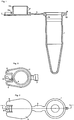
- FIG. 1 shows the schematic representation of a reaction vessel in section,
- FIG. 2 shows the top view of the lid of the reaction vessel according to FIG. 1,
- FIG. 3 shows the view of the reaction vessel according to FIG. 1 from below,
- FIG. 4 shows the reaction vessel according to FIGS. 1 to 3 in the closed state,
- FIG. 5 shows the schematic sectional illustration of a reaction vessel with an elastic sealing element,
- Figure 6 shows the partial section through a modified reaction vessel with a lid, on section along line A in Figure 7 and
- FIG. 7 shows a top view of the cover according to FIG. 6.
Gemäss Figur 1 bis 4 ist ein im Spritzguss-Verfahren hergestelltes Reaktionsgefäss 1 einstückig mit einem Deckel 2 ausgebildet. Reaktionsgefäss 1 und Deckel 2 sind dabei derart durch einen Steg 3 verbunden, dass der Steg 3 einerseits den Deckel 2 unverlierbar am Reaktionsgefäss 1 hält und andererseits gemäss Figur 4 der Deckel 2 durch den Steg 3 im geschlossenen Zustand scharnierartig in seiner Lage gehalten wird. Der Deckel 2 weist ein zylindrisches Dichtungsteil 4 auf, das am Ende mit einem wulstartigen Dichtungselement 4a versehen ist. Das Dichtungselement 4a schnappt beim Schliessen des Deckels in eine entsprechende ringförmige Vertiefung 1a in der Innenwand des Reaktionsgefässes 1. Insoweit handelt es sich um einen Schnappverschluss, wobei das Dichtungselement 4a die Doppelfunktion des Dichtens und Einschnappens übernimmt.According to FIGS. 1 to 4, a
Am Deckel 2 sind zwei Vorsprünge 5, 6 vorgesehen, welche die Funktion von Abdrücknasen übernehmen. Zum Oeffnen des geschlossenen Reaktionsgefässes 1 kann der Benutzer einfach mit dem Daumen gegen den Vorsprung 5 oder 6 drücken und dabei das Dichtteil 4 nach oben aus dem Gefäss 1 schieben. Zwischen den beiden Vorsprüngen 5, 6 ist eine Biegelasche 7 mit einer Oeffnung 8 angeordnet. Im unverbogenen Zustand fluchtet die Biegelasche 7 mit den Vorsprüngen 5 und 6.On the
Nach dem Schliessen des Reaktionsgefässes 1 durch den Deckel 2 lässt sich die Biegelasche 7 gemäss Figur 4 derart nach unten biegen, dass die Oeffnung 5 über einen am Gefäss 1 vorgesehenen Sicherungsstift 9 schnappt. Der Sicherungsstift 9 weist an seiner Unterseite eine Rastkante 10 auf, welche verhindert, dass die Biegelasche 7 sich von alleine vom Sicherungsstift 9 löst. Am Deckel 2 ist ein lippenartiges Federelement 6a vorgesehen, das beim Schliessen des Deckels 2 zusammengepresst wird. Dabei entsteht eine in Richtung des Pfeils A (Fig. 4) wirkende Kraft, welche die Biegelasche 7 hinter die Rastkante 10 zieht.After the
Zum Oeffnen lässt sich dagegen die Biegelasche 7 einfach über den Sicherungsstift 9 streifen und der Deckel 2 sodann an den Vorsprüngen 5 und 6 anheben. Dies kann auch einhändig durchgeführt werden.For opening, on the other hand, the
Bei den Ausführungsbeispielen gemäss Figur 1 bis 4 wird der Deckel 2 durch den Steg 3 mit seiner Scharnierfunktion und die Biegelasche 7 im geschlossenen Zustand gesichert. Selbstverständlich ist es auch denkbar, nicht nur eine, sondern mehrere Biegelaschen vorzusehen, wenn ein Behälter mehrfach gesichert werden muss. Denkbar ist es auch, statt des Stegs 3 ebenfalls eine Biegelasche 7 vorzusehen.In the exemplary embodiments according to FIGS. 1 to 4, the
Die Vorsprünge 5 und 6 schützen die Biegelasche 7 besonders vorteilhaft gegen unbeabsichtigtes Oeffnen. Alternativ wäre es selbstverständlich auch denkbar, nur einen Vorsprung vorzusehen oder einen tellerförmigen, überstehenden Rand vorzusehen, mittels dessen der Deckel 2 angehoben und geöffnet werden kann. Obwohl die Anordnung der Biegelasche 7 am Deckel 2 besonders einfache Herstellung und Manipulation ermöglicht, sind auch Ausführungsformen denkbar, bei denen die Biegelasche 7 am Gefäss 1 und der Sicherungsstift 9 am Deckel 2 befestigt ist.The
Figur 5 zeigt ein Ausführungsbeispiel der Erfindung, bei welchem ein elastischer Dichtring 11 zwischen Deckel 2 und Rand 12 des Gefässes 1 angeordnet ist. Durch den elastischen Dichtring 11 wird besonders gute Abdichtung des Gefässes 1 bewirkt. Beim Schliessen wird der Deckel 2 zunächst so fest in das Gefäss 1 hinein gedrückt, dass die Biegelasche 7 über die Rastkante 10 des Sicherungsstiftes 9 geschoben werden kann. Danach kann sich der Dichtring 11 wieder etwas entspannen, wobei die Biegelasche 7 fest unter die Rastkante 10 gezogen wird.FIG. 5 shows an exemplary embodiment of the invention, in which an
Beim Ausführungsbeispiel gemäss Figur 6 und 7 ist ein Deckel 14 dargestellt, der die Mündung eines Reaktionsgefässes 1 von aussen umgibt. Analog dem Ausführungsbeispiel gemäss Figur 1 bis 4 ist am Deckel 14 ein wulstartiges Dichtelement 14a vorgesehen, das die Gefässmündung 15 dichtend umgreift und in eine komplementäre Rille 1a einschnappt. Zusätzlich ist noch am Boden des Deckels 14 eine ringförmige elastische Dichtung 16 vorgesehen, welche die Stirnseite der Gefässmündung 15 abdichtet. Am Gefäss 1 sind zwei Biegelaschen 7 vorgesehen, die derart nach oben gebogen werden können, dass sie analog den Ausführungsbeispielen gemäss Figur 1 bis 5 mit Oeffnungen 8 über Sicherungsstifte 9 geschoben werden können, die am Deckel 14 befestigt sind. Die Sicherungsstife 9 sind beidseitig durch Vorsprünge 5, 6 eingefasst, wodurch auch die Biegelaschen 7 geschützt werden.In the exemplary embodiment according to FIGS. 6 and 7, a
Claims (9)
Applications Claiming Priority (2)
| Application Number | Priority Date | Filing Date | Title |
|---|---|---|---|
| CH366890 | 1990-11-19 | ||
| CH3668/90 | 1990-11-19 |
Publications (1)
| Publication Number | Publication Date |
|---|---|
| EP0487448A1 true EP0487448A1 (en) | 1992-05-27 |
Family
ID=4260945
Family Applications (1)
| Application Number | Title | Priority Date | Filing Date |
|---|---|---|---|
| EP91810845A Withdrawn EP0487448A1 (en) | 1990-11-19 | 1991-11-01 | Plastic reaction vessel for small liquid samples |
Country Status (3)
| Country | Link |
|---|---|
| US (1) | US5270011A (en) |
| EP (1) | EP0487448A1 (en) |
| JP (1) | JPH04267756A (en) |
Cited By (8)
| Publication number | Priority date | Publication date | Assignee | Title |
|---|---|---|---|---|
| EP0651718A1 (en) * | 1992-07-20 | 1995-05-10 | Innervision, Inc. | Multiple cap seal for containers |
| DE9418060U1 (en) * | 1994-11-11 | 1996-03-14 | Sc Sanguis Counting Kontrollbl | Sample tube and end cap, especially for capillary blood collection |
| EP0820813A2 (en) * | 1996-07-22 | 1998-01-28 | Becton, Dickinson and Company | A closure |
| WO2008148780A1 (en) * | 2007-06-05 | 2008-12-11 | Endress+Hauser Wetzer Gmbh+Co. Kg | Device for determining and/or monitoring a process variable |
| EP2138235A1 (en) * | 2004-03-16 | 2009-12-30 | Prescribe Genomics Co. | Container with lid |
| WO2012083995A1 (en) * | 2010-12-23 | 2012-06-28 | Eppendorf Ag | Reaction vessel having a cover |
| US8540948B2 (en) | 2010-12-23 | 2013-09-24 | Eppendorf Ag | Lidded container |
| WO2019032636A1 (en) * | 2017-08-08 | 2019-02-14 | Csp Technologies, Inc. | Moisture tight containers and methods of making and using the same |
Families Citing this family (68)
| Publication number | Priority date | Publication date | Assignee | Title |
|---|---|---|---|---|
| US5225165A (en) * | 1992-05-11 | 1993-07-06 | Brandeis University | Microcentrifuge tube with upwardly projecting lid extension |
| US5620662A (en) * | 1993-08-23 | 1997-04-15 | Brandeis University | Temporary liquid storage cavities in a centrifuge tube lid |
| EP1245286B1 (en) * | 1993-10-22 | 2009-11-25 | Abbott Laboratories | Reaction tube and method of use to minimize contamination |
| US5354539A (en) * | 1993-11-12 | 1994-10-11 | Hovatter Kenneth R | Microtube having press-to-seal and twist-to-lock closure cap |
| US5683659A (en) * | 1995-02-22 | 1997-11-04 | Hovatter; Kenneth R. | Integral assembly of microcentrifuge strip tubes and strip caps |
| US5958778A (en) * | 1995-09-22 | 1999-09-28 | The United States Of America As Represented By The Department Of Health And Human Services | Container for drying biological samples, method of making such container, and method of using same |
| JP2939722B2 (en) * | 1996-05-17 | 1999-08-25 | 株式会社不二コーン製作所 | Mold tray with bent portion, method for manufacturing the same, and apparatus for manufacturing the same |
| US5817066A (en) * | 1996-10-09 | 1998-10-06 | Goforth; Thomas Leonard | Bulb-type irrigation syringe |
| JP3366233B2 (en) * | 1997-09-30 | 2003-01-14 | 富士通株式会社 | Fixing structure of resin cover |
| US6312648B1 (en) | 1998-01-12 | 2001-11-06 | The United States Of America As Represented By The Department Of Health And Human Services | Applicator system |
| US6086371A (en) * | 1998-02-05 | 2000-07-11 | Sulzer Orthopedics Inc. | Dental implant delivery system having driver mount with removable flange |
| US6076660A (en) * | 1998-02-05 | 2000-06-20 | Sulzer Calcitek Inc. | Vial for dental implant delivery system |
| US5961330A (en) * | 1998-04-09 | 1999-10-05 | Sulzer Calcitek Inc. | Vial for dental implant delivery system |
| BR9916990A (en) * | 1999-01-27 | 2001-11-06 | Creanova Ag | Injected closure, closed |
| WO2001044102A2 (en) * | 1999-11-10 | 2001-06-21 | Capitol Vial, Inc. | A tamper-proof container cap assembly and related methods |
| US7413083B2 (en) * | 2002-04-11 | 2008-08-19 | Csp Technologies, Inc. | Desiccant vial assembly for effervescent tablets |
| US20040048392A1 (en) * | 2002-09-09 | 2004-03-11 | The Gov't Of The U.S.A As Represented By The Secretary Of The Dept.Of Health And Human Services | Container for drying biological samples, method of making such container, and method of using same |
| US6772902B1 (en) * | 2003-06-20 | 2004-08-10 | Colin White | One-piece molded child-proof container |
| FR2858301B1 (en) * | 2003-07-29 | 2006-05-26 | Airsec | WATERPROOF DESSICATIVE CONTAINER FOR PACKAGING AMBIENT HUMIDITY-SENSITIVE PRODUCTS |
| US20050042145A1 (en) * | 2003-08-22 | 2005-02-24 | Sysmex Corporation | Container for analyzer, detection container, reaction container and packing container for storing detection container |
| EP1671701B1 (en) * | 2004-12-18 | 2011-12-21 | Gemü GmbH | Sample and reaction container |
| FR2889461B1 (en) * | 2005-08-04 | 2007-10-26 | Gilson Sas Soc Par Actions Sim | LABORATORY MICROTUBE. |
| DE102005058399A1 (en) * | 2005-12-01 | 2007-06-14 | Eppendorf Ag | Deckelgefäß |
| US7451870B2 (en) * | 2006-02-06 | 2008-11-18 | Zimmer Dental, Inc. | Medical implant package with a cap having a cavity |
| WO2007109166A2 (en) | 2006-03-17 | 2007-09-27 | Csp Technologies, Inc. | Tab release child safety feature |
| US7581656B2 (en) * | 2006-07-17 | 2009-09-01 | Rexam Prescription Products Inc. | One-piece box-shaped container with large label wrap surface |
| US7749452B2 (en) * | 2007-01-25 | 2010-07-06 | Gemu Gmbh | Sample and reaction container |
| US8056749B2 (en) * | 2007-05-07 | 2011-11-15 | Rexam Closure Systems Inc. | Flip-lid dispensing closure and package |
| ATE543096T1 (en) * | 2007-09-03 | 2012-02-15 | Airsec Sas | TEST STRIP CONTAINERS |
| CA2602398A1 (en) * | 2007-10-16 | 2009-04-16 | Gaetan Milante | Medication vial |
| WO2009063089A1 (en) * | 2007-11-16 | 2009-05-22 | Airsec S.A.S. | Container |
| US8714404B2 (en) | 2008-03-07 | 2014-05-06 | Orbis Canada Limited | Refuse container |
| US20100140283A1 (en) * | 2008-12-08 | 2010-06-10 | Brozell Leonora M | Bottom-fill container with an integral child-resistant lid |
| CA2990646C (en) * | 2009-02-06 | 2021-10-05 | Becton, Dickinson And Company | Disposable pen needle with re-use prevention features |
| US20100281955A1 (en) * | 2009-05-05 | 2010-11-11 | Pressure Biosciences Inc. | Microtube and related methods therefor |
| BR112012032347A2 (en) * | 2010-06-18 | 2016-11-08 | Pathogen Detection Systems Inc | container, method for storing a sample in a container having a lid and method for testing a sample for the presence of a molecule of interest |
| US8887912B2 (en) * | 2010-08-16 | 2014-11-18 | Becton, Dickinson And Company | Living hinge needle assembly for medicament delivery device |
| US8631966B2 (en) * | 2010-08-23 | 2014-01-21 | Starplex Scientific Inc. | Specimen container with cap having a snap-fit partially open position |
| US20120048287A1 (en) * | 2010-08-24 | 2012-03-01 | White John L | Devices, Systems, and Methods for Cleaning Teeth |
| DE102010055776A1 (en) | 2010-12-23 | 2012-06-28 | Eppendorf Ag | Deckelgefäß |
| EP2517791A1 (en) * | 2011-04-18 | 2012-10-31 | Vibod GmbH | Sample tube with improved lid |
| CA2835654A1 (en) | 2011-06-01 | 2012-12-06 | Streck, Inc. | Rapid thermocycler system for rapid amplification of nucleic acids and related methods |
| WO2013074391A1 (en) * | 2011-11-10 | 2013-05-23 | Biofire Diagnostics, Inc. | Loading vials |
| EP2825865B1 (en) | 2012-03-09 | 2020-07-22 | Ubiquitome Limited | Portable device for detecting molecule(s) |
| WO2014025398A1 (en) | 2012-08-10 | 2014-02-13 | Streck, Inc. | Real-time optical system for polymerase chain reaction |
| US10322856B2 (en) * | 2013-06-04 | 2019-06-18 | Csp Technologies, Inc. | Container having a child resistant closure with a small profile |
| US9533803B1 (en) * | 2013-06-04 | 2017-01-03 | Csp Technologies, Inc. | Container having a child resistant closure with a small profile |
| EP2972219B1 (en) | 2013-03-15 | 2022-01-19 | Abbott Laboratories | Automated reagent manager of a diagnostic analyzer system |
| US9513303B2 (en) | 2013-03-15 | 2016-12-06 | Abbott Laboratories | Light-blocking system for a diagnostic analyzer |
| US10518943B2 (en) | 2013-03-15 | 2019-12-31 | Tc Heartland Llc | Container with valve |
| USD728378S1 (en) | 2013-03-15 | 2015-05-05 | Tc Heartland Llc | Container |
| WO2014144759A1 (en) | 2013-03-15 | 2014-09-18 | Abbott Laboratories | Linear track diagnostic analyzer |
| US9108772B2 (en) | 2013-03-15 | 2015-08-18 | Scientific Specialties, Inc. | Container latching systems for one-handed operation |
| CA2916990C (en) | 2013-06-28 | 2023-05-23 | Streck, Inc. | Devices for real-time polymerase chain reaction |
| USD754361S1 (en) | 2013-09-06 | 2016-04-19 | Theranos, Inc. | Sample container |
| HUE056725T2 (en) * | 2015-02-25 | 2022-03-28 | Airnov Inc | Container for loosely stored products and method for opening such container |
| JP6365348B2 (en) * | 2015-02-27 | 2018-08-01 | ブラザー工業株式会社 | Liquid storage device and liquid consumption device |
| WO2016188533A1 (en) | 2015-05-26 | 2016-12-01 | Københavns Universitet (Ku) | Enzyme activity assay system and devices |
| CH711648A1 (en) * | 2015-10-14 | 2017-04-28 | Alpla Werke Alwin Lehner Gmbh & Co Kg | Injection-molded preform for producing a plastic container in a blow molding process, plastic container produced therefrom and production method for the preform or the plastic container. |
| US10961030B2 (en) | 2017-04-24 | 2021-03-30 | Csp Technologies, Inc. | Slidably openable child resistant container |
| US10889416B2 (en) | 2017-04-24 | 2021-01-12 | Csp Technologies, Inc. | Child resistant container and method of opening same |
| US10961750B2 (en) * | 2017-09-29 | 2021-03-30 | Sumitomo Riko Company Limited | Cover unit |
| US10947018B2 (en) | 2018-06-06 | 2021-03-16 | Clarity, Inc. | Cups and containers with a living hinge and sleeves |
| US11254473B2 (en) | 2018-06-06 | 2022-02-22 | Clarity, Inc. | Cups and containers with a living hinge and sleeves |
| USD873613S1 (en) | 2018-06-07 | 2020-01-28 | Clarity, Inc. | Cup with a lid |
| USD885838S1 (en) | 2018-06-07 | 2020-06-02 | Clarity, Inc. | Cup with a living hinge and an attached lid having an outer lip and an inner dual seal |
| JP7318925B2 (en) * | 2019-10-18 | 2023-08-01 | 株式会社塚田メディカル・リサーチ | medical device cap |
| US20210145560A1 (en) * | 2019-11-20 | 2021-05-20 | Invo Bioscience, Inc. | Intravaginal culture incubation container and method |
Citations (5)
| Publication number | Priority date | Publication date | Assignee | Title |
|---|---|---|---|---|
| FR338573A (en) * | 1903-12-31 | 1904-05-28 | Leocade Arthur Bruzeau | New process and apparatus for low temperature sterilization by boiling in vacuum |
| FR2006735A1 (en) * | 1968-04-23 | 1970-01-02 | Schoeller & Co Kg | Plastic first aid box with detachable flanged lid |
| US4684024A (en) * | 1985-12-19 | 1987-08-04 | Par-Pak Limited | Cover for baked goods |
| EP0341342A2 (en) * | 1988-05-09 | 1989-11-15 | Multi-Technology, Inc. | Fail safe releasable locks for capped disposable centrifuge containers |
| EP0341372A2 (en) * | 1988-05-09 | 1989-11-15 | Multi-Technology, Inc. | Disposable laboratory testing devices |
Family Cites Families (9)
| Publication number | Priority date | Publication date | Assignee | Title |
|---|---|---|---|---|
| DE1275795B (en) * | 1963-01-28 | 1968-08-22 | Eppendorf Geraetebau Netheler | Reaction vessel for small amounts of liquid |
| US3999678A (en) * | 1975-12-01 | 1976-12-28 | Sobrefina Sa | Closing arrangement for packing containers |
| DE3402276C1 (en) * | 1984-01-24 | 1985-02-21 | Eppendorf Gerätebau Netheler + Hinz GmbH, 2000 Hamburg | Plastic reaction vessel for small amounts of liquid |
| CA1311346C (en) * | 1984-12-11 | 1992-12-15 | Neville Green | Fastening device |
| US4664273A (en) * | 1986-04-29 | 1987-05-12 | Simon B Kenneth | Child-resistant container with resistance indicating means |
| US5005721A (en) * | 1987-05-08 | 1991-04-09 | Abbott Laboratories | Vial seal |
| US4852770A (en) * | 1987-12-31 | 1989-08-01 | Specialty Packaging Licensing Co. | Child-resistant dispensing closure |
| US4787526A (en) * | 1988-02-26 | 1988-11-29 | Pehr Harold T | Container closure having child protective fastening means |
| US5031784A (en) * | 1990-03-30 | 1991-07-16 | Wright Frank S | One-piece child-resistant closure |
-
1991
- 1991-11-01 EP EP91810845A patent/EP0487448A1/en not_active Withdrawn
- 1991-11-08 US US07/789,338 patent/US5270011A/en not_active Expired - Fee Related
- 1991-11-19 JP JP3303392A patent/JPH04267756A/en active Pending
Patent Citations (5)
| Publication number | Priority date | Publication date | Assignee | Title |
|---|---|---|---|---|
| FR338573A (en) * | 1903-12-31 | 1904-05-28 | Leocade Arthur Bruzeau | New process and apparatus for low temperature sterilization by boiling in vacuum |
| FR2006735A1 (en) * | 1968-04-23 | 1970-01-02 | Schoeller & Co Kg | Plastic first aid box with detachable flanged lid |
| US4684024A (en) * | 1985-12-19 | 1987-08-04 | Par-Pak Limited | Cover for baked goods |
| EP0341342A2 (en) * | 1988-05-09 | 1989-11-15 | Multi-Technology, Inc. | Fail safe releasable locks for capped disposable centrifuge containers |
| EP0341372A2 (en) * | 1988-05-09 | 1989-11-15 | Multi-Technology, Inc. | Disposable laboratory testing devices |
Cited By (15)
| Publication number | Priority date | Publication date | Assignee | Title |
|---|---|---|---|---|
| EP0651718A1 (en) * | 1992-07-20 | 1995-05-10 | Innervision, Inc. | Multiple cap seal for containers |
| EP0651718A4 (en) * | 1992-07-20 | 1995-12-27 | Innervision Inc | Multiple cap seal for containers. |
| DE9418060U1 (en) * | 1994-11-11 | 1996-03-14 | Sc Sanguis Counting Kontrollbl | Sample tube and end cap, especially for capillary blood collection |
| US6705482B2 (en) | 1996-07-22 | 2004-03-16 | Steven Robert Savitz | Ball and socket closure |
| EP0820813A3 (en) * | 1996-07-22 | 1998-09-16 | Becton, Dickinson and Company | A closure |
| US6161712A (en) * | 1996-07-22 | 2000-12-19 | Becton Dickinson And Company | Ball and socket closure |
| EP0820813A2 (en) * | 1996-07-22 | 1998-01-28 | Becton, Dickinson and Company | A closure |
| EP1894630A1 (en) * | 1996-07-22 | 2008-03-05 | Becton, Dickinson & Company | A closure |
| EP2138235A1 (en) * | 2004-03-16 | 2009-12-30 | Prescribe Genomics Co. | Container with lid |
| US8123065B2 (en) | 2004-03-16 | 2012-02-28 | Prescribe Genomics Co. | Container with lid |
| WO2008148780A1 (en) * | 2007-06-05 | 2008-12-11 | Endress+Hauser Wetzer Gmbh+Co. Kg | Device for determining and/or monitoring a process variable |
| WO2012083995A1 (en) * | 2010-12-23 | 2012-06-28 | Eppendorf Ag | Reaction vessel having a cover |
| US8540948B2 (en) | 2010-12-23 | 2013-09-24 | Eppendorf Ag | Lidded container |
| WO2019032636A1 (en) * | 2017-08-08 | 2019-02-14 | Csp Technologies, Inc. | Moisture tight containers and methods of making and using the same |
| US11325771B2 (en) | 2017-08-08 | 2022-05-10 | Csp Technologies, Inc. | Moisture tight containers and methods of making and using the same |
Also Published As
| Publication number | Publication date |
|---|---|
| US5270011A (en) | 1993-12-14 |
| JPH04267756A (en) | 1992-09-24 |
Similar Documents
| Publication | Publication Date | Title |
|---|---|---|
| EP0487448A1 (en) | Plastic reaction vessel for small liquid samples | |
| EP3135599B1 (en) | Applicator head for a liquid dispenser and liquid dispenser | |
| EP0976663A1 (en) | Closure with hinged lid | |
| DE2658713C2 (en) | Container lock construction | |
| EP0766955B1 (en) | Port system for a bag | |
| DE3140234C2 (en) | Container lid made from an elastic, deformable plastic | |
| DE2738243A1 (en) | TILTING NOZZLE LATCH | |
| DE1176505B (en) | Reusable sealing cap for liquid containers, especially atomizers for liquids | |
| EP0240604B1 (en) | Insulated canister provided with an elastic sealing | |
| DE2000413A1 (en) | Container lock | |
| DE1177709B (en) | Waterproof junction box or junction box made of insulating material | |
| DE2301255A1 (en) | CLOSING LINK FOR NON-RETURN VALVE | |
| EP1675779B1 (en) | Device for sealing the opening of a container | |
| EP0046478B1 (en) | Fastening devices for tarpaulins with sheet metal eyelets riveted into place | |
| DE3535554A1 (en) | QUICK RELEASE FOR A CONTAINER | |
| DE926369C (en) | Water control valve for refrigeration machines | |
| DE4343064A1 (en) | Liquid container closure | |
| DE10213125A1 (en) | Adapter with a slit valve, e.g. for delivering shower gel, comprises a clamping sleeve formed on a tensioning member, and a slit valve formed by injection molding | |
| EP0254810A2 (en) | Cap unit for dropper system | |
| AT234574B (en) | Plastic containers | |
| AT405045B (en) | WARRANTY LOCK FOR CONTAINERS | |
| DE141477C (en) | ||
| DE1655806C3 (en) | Screw cap for the container of the washing liquid of a windshield washer system for motor vehicles | |
| DE1482571C (en) | Container lock | |
| DE1968009U (en) | PLASTIC LOCKING INSERT FOR LIQUID CONTAINER. |
Legal Events
| Date | Code | Title | Description |
|---|---|---|---|
| PUAI | Public reference made under article 153(3) epc to a published international application that has entered the european phase |
Free format text: ORIGINAL CODE: 0009012 |
|
| AK | Designated contracting states |
Kind code of ref document: A1 Designated state(s): CH DE ES FR GB IT LI |
|
| 17P | Request for examination filed |
Effective date: 19921030 |
|
| 17Q | First examination report despatched |
Effective date: 19940324 |
|
| STAA | Information on the status of an ep patent application or granted ep patent |
Free format text: STATUS: THE APPLICATION IS DEEMED TO BE WITHDRAWN |
|
| 18D | Application deemed to be withdrawn |
Effective date: 19940804 |